
A Three-Dimensional Orthogonal Receiving Coil for In Vivo Microrobot Wireless Power Transmission Systems

Abstract
:1. Introduction
2. Wireless Power Transmission for Microrobots
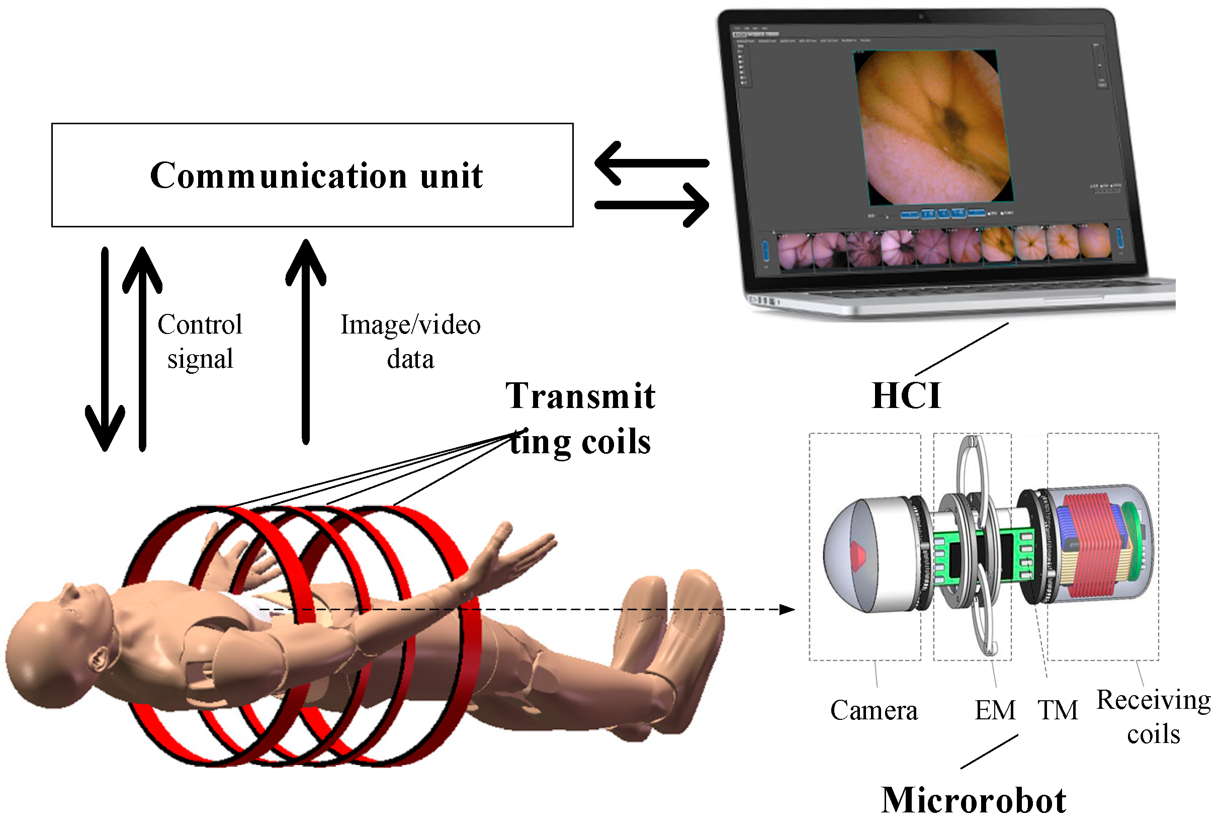
2.1. System Overview
2.2. Working Principle of WPT
3. Design of Receiving End in WPT
3.1. Design of Energy Management Circuit
3.1.1. Rectifier Circuit
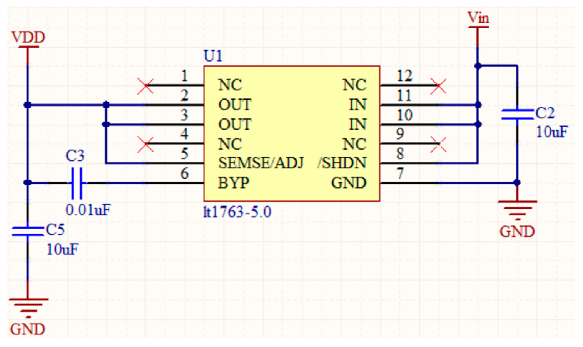
3.1.2. Regulator Circuit
3.2. Design and Optimization of Receiving Coil
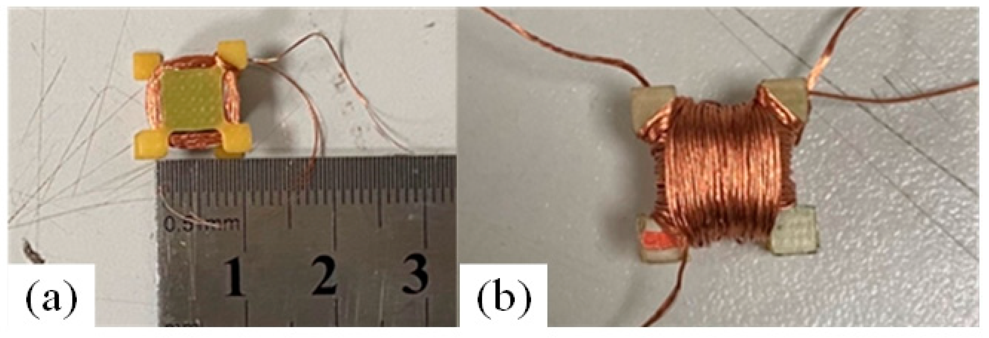
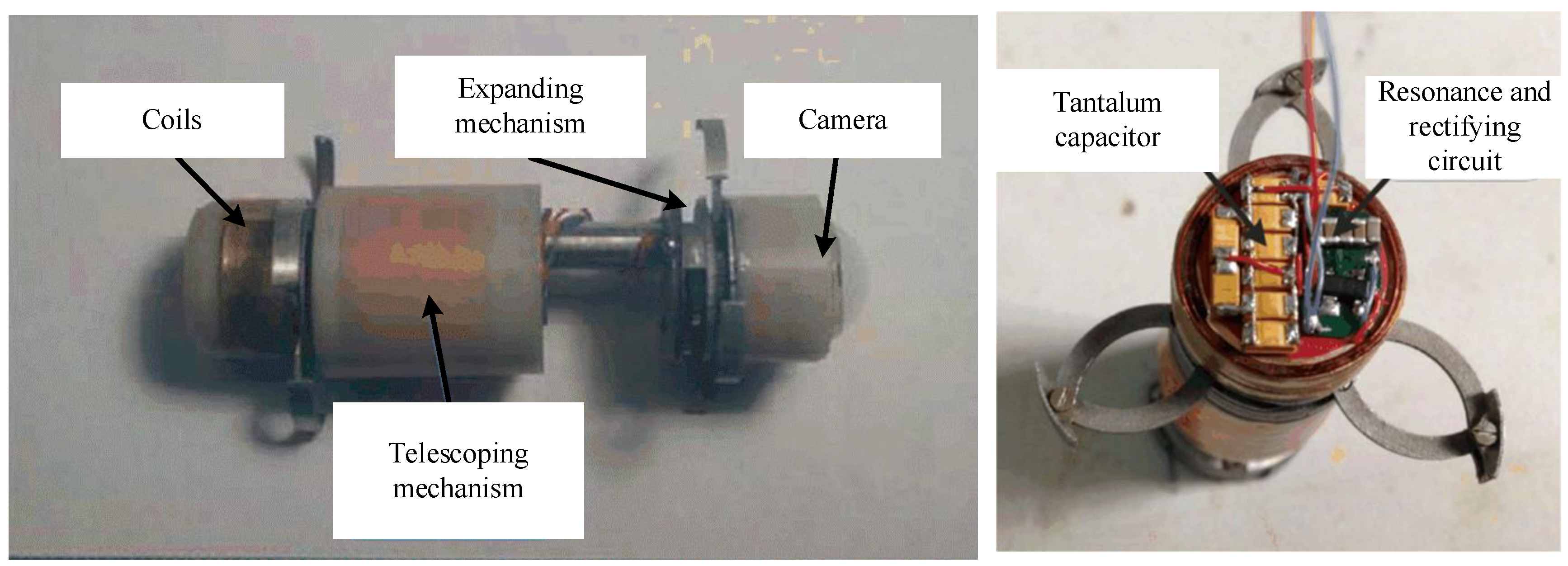
3.2.1. 3D Orthogonal Receiving Coil
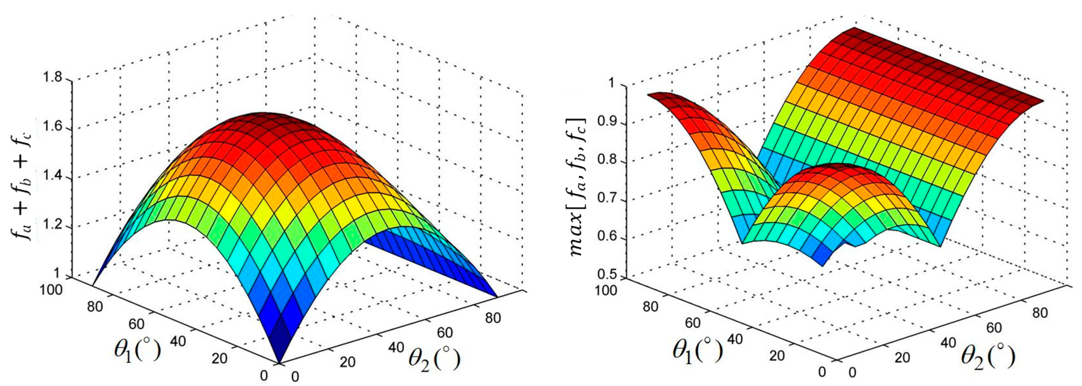
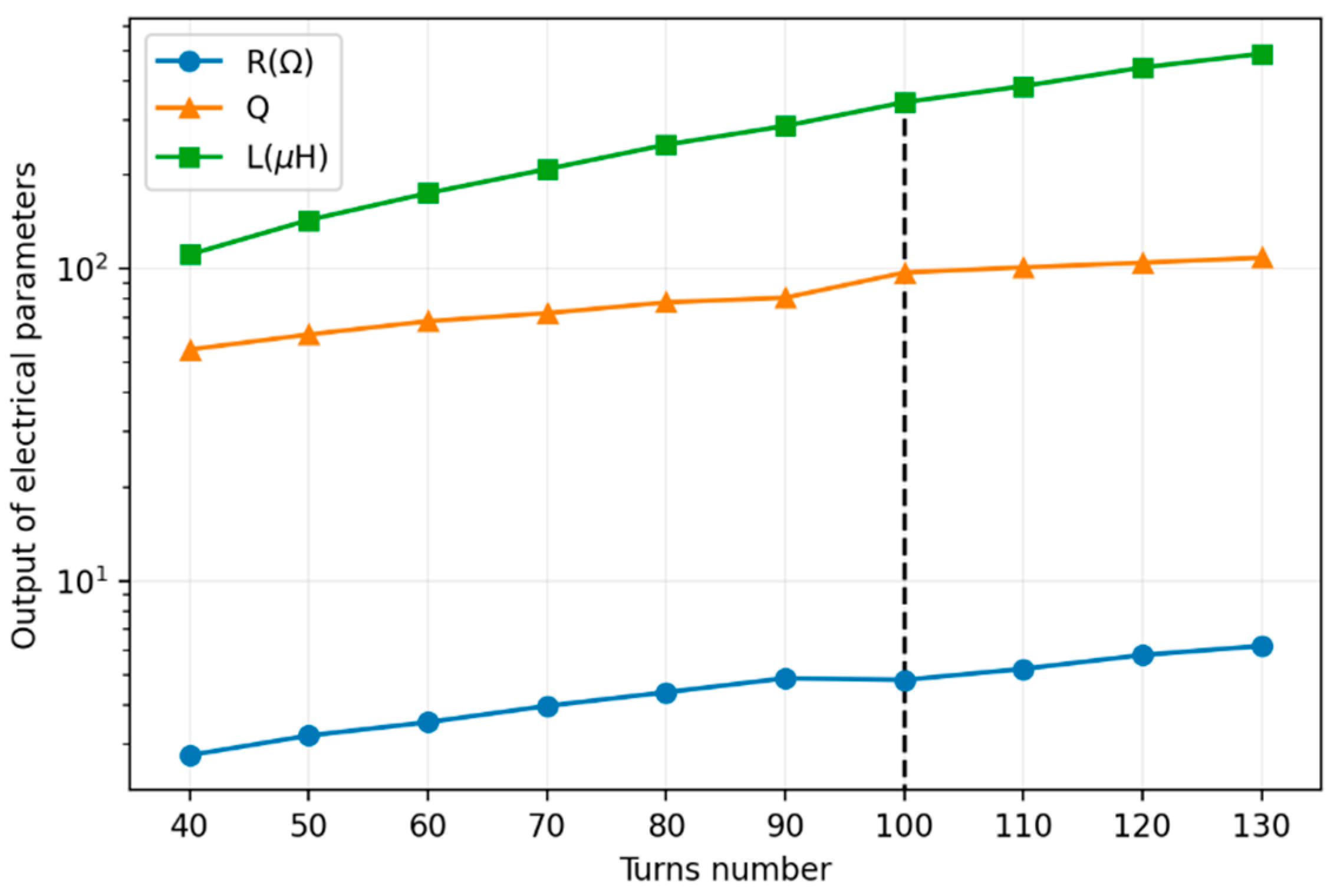
3.2.2. Optimization of 3D Coils
4. Experiments
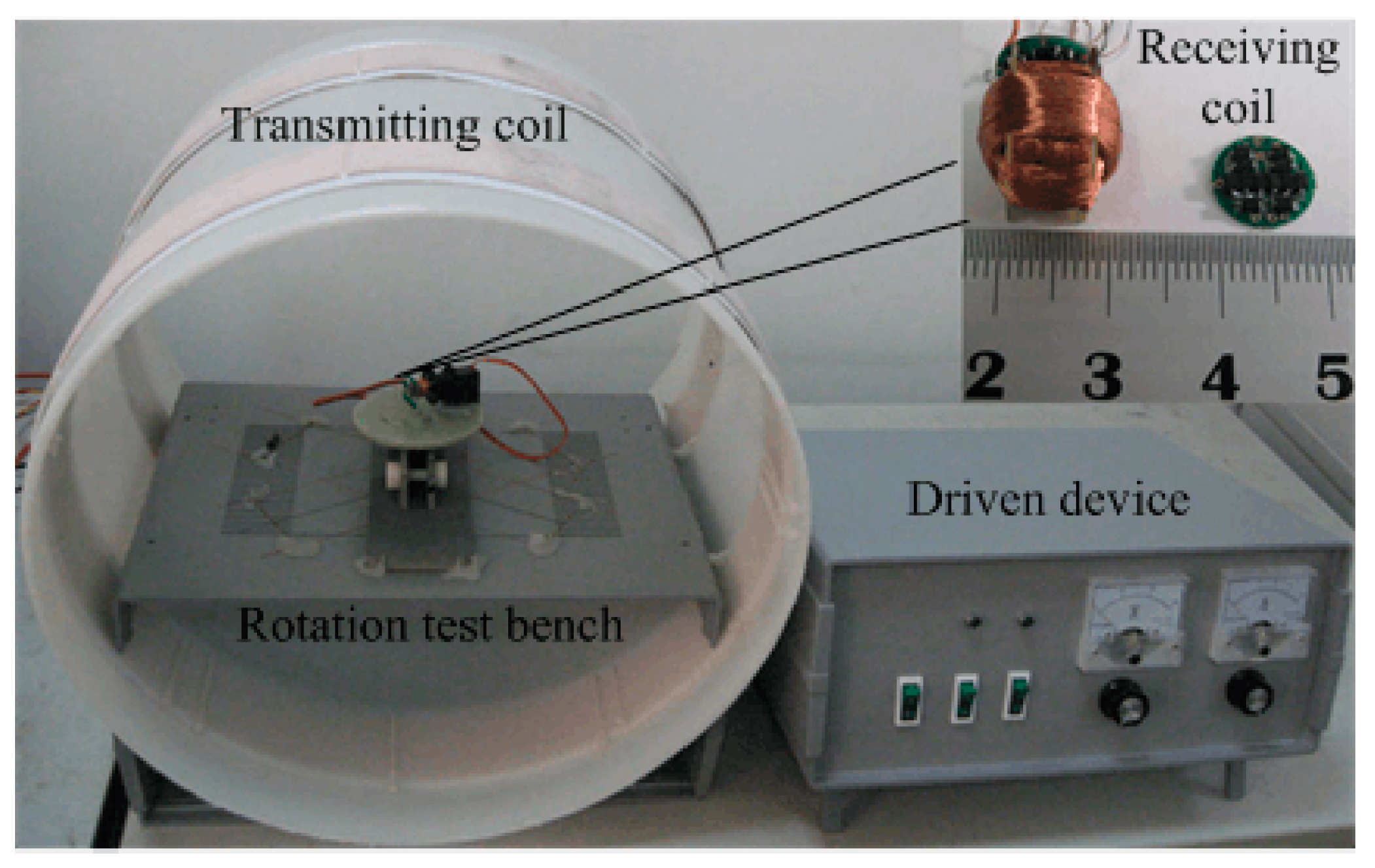
4.1. Bench Tests
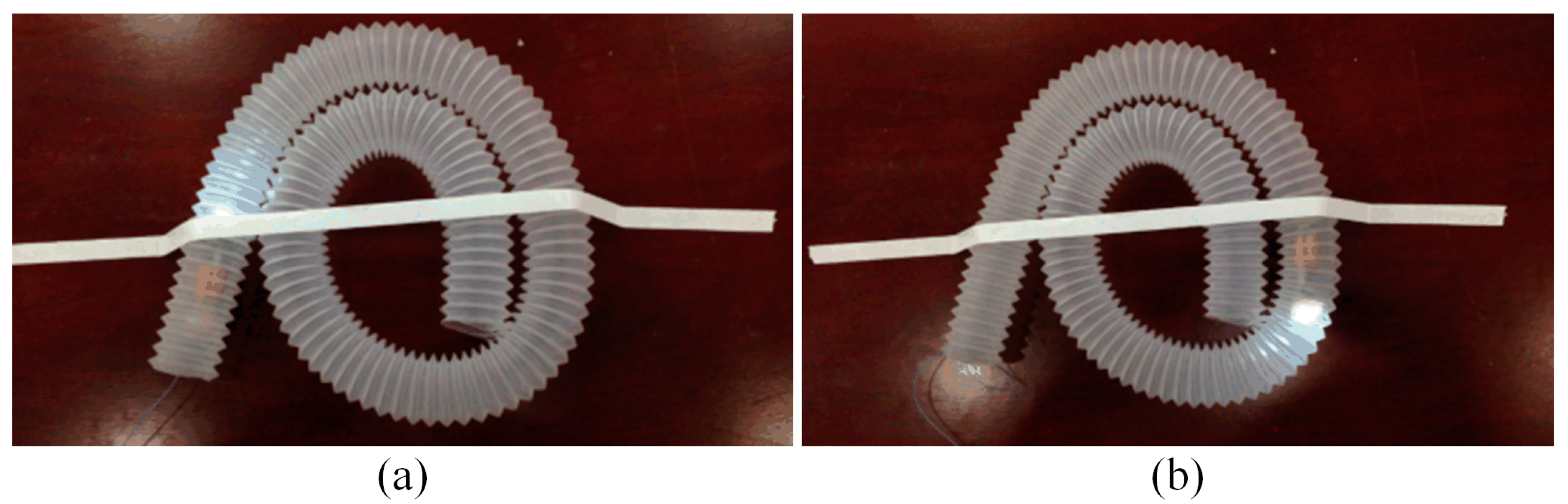
4.2. In Vitro Experiments
5. Discussion and Conclusions
Author Contributions
Funding
Institutional Review Board Statement
Informed Consent Statement
Data Availability Statement
Conflicts of Interest
References
- Yang, Y. The future of capsule endoscopy: The role of artificial intelligence and other technical advancements. Clin. Endosc. 2020, 53, 387. [Google Scholar] [CrossRef] [PubMed]
- Hosoe, N.; Kamiya, K.J.L.L.; Hayashi, Y.; Sujino, T.; Ogata, H.; Kanai, T. Current status of colon capsule endoscopy. Dig. Endosc. 2021, 33, 529–537. [Google Scholar] [CrossRef] [PubMed]
- Hosoe, N.; Takabayashi, K.; Ogata, H.; Kanai, T. Capsule endoscopy for small-intestinal disorders: Current status. Dig. Endosc. 2019, 31, 498–507. [Google Scholar] [CrossRef] [PubMed]
- Tsuchida, Y.; Ito, S.; Fukui, M. Wireless capsule endoscopy: A new tool for cancer screening in the colon with deep-learning-based polyp recognition. Proc. IEEE 2019, 108, 178–197. [Google Scholar]
- Jia, Z.; Yan, G.; Zhu, B. Portable wireless power transmission system for video capsule endoscopy. J. Med. Eng. Technol. 2014, 38, 351–358. [Google Scholar]
- Han, D.; Yan, G.; Wang, Z.; Jiang, P.; Liu, D.; Zhao, K.; Ma, J. The modelling, analysis, and experimental validation of a novel micro-robot for diagnosis of intestinal diseases. Micromachines 2020, 11, 896. [Google Scholar] [CrossRef] [PubMed]
- Basar, M.R.; Ahmad, M.Y.; Cho, J.; Ibrahim, F. An improved wearable resonant wireless power transfer system for biomedical capsule endoscope. IEEE Trans. Ind. Electron. 2018, 65, 7772–7781. [Google Scholar] [CrossRef]
- Lenaerts, B.; Puers, R. Inductive powering of a freely moving system. Sens. Actuators A Phys. 2005, 123, 522–530. [Google Scholar] [CrossRef]
- Ahmed Khan, S.; Ali, A.; Shiyou, Y.; Tong, J.; Guerrero, J.M. Optimized design of embedded air coil for small satellites with various dimensions. J. Aerosp. Inf. Syst. 2021, 18, 269–279. [Google Scholar] [CrossRef]
- Yang, Y.; Xie, X.; Li, G.; Huang, Y.; Wang, Z. A combined transmitting coil design for high efficiency WPT of endoscopic capsule. In Proceedings of the 2015 IEEE International Symposium on Circuits and Systems (ISCAS), Lisbon, Portugal, 24–27 May 2015; pp. 97–100. [Google Scholar]
- Liu, T.; Schnabel, A.; Voigt, J.; Sun, Z.; Li, L. A three-step model for optimizing coil spacings inside cuboid-shaped magnetic shields. AIP Adv. 2020, 10, 115004. [Google Scholar] [CrossRef]
- Basar, M.R.; Ahmad, M.Y.; Cho, J.; Ibrahim, F. Stable and high-efficiency wireless power transfer system for robotic capsule using a modified Helmholtz coil. IEEE Trans. Ind. Electron. 2017, 64, 1113–1122. [Google Scholar] [CrossRef]
- Xu, C.; Zhuang, Y.; Huang, Y.; Zhou, J. Against Misalignment Wireless Power Transfer System Using a Modified Helmholtz Coil. In Proceedings of the URSI GASS 2020, Rome, Italy, 28 August–4 September 2021. [Google Scholar]
- Meng, Y.; Wang, Z.; Jiang, P.; Wang, W.; Chen, F.; Yan, G. Optimization and analysis of Helmholtz-like three-coil wireless power transfer system applied in gastrointestinal robots. J. Power Electron. 2020, 20, 1088–1098. [Google Scholar] [CrossRef]
- Han, D.; Yan, G.; Kuang, S.; Wang, W.; Zhao, K. Preliminary Study on a Three-coil Wireless Power Transfer System for Endoscope Micro-robot of Intestinal Diagnosis: Design, Optimization and Validation. J. Electr. Eng. Technol. 2022, 17, 2213–2224. [Google Scholar] [CrossRef]
- Gao, J.; Yan, G.; Shi, Y.; Cao, H.; Huang, K.; Gao, H.; Liu, J. Analysis of connection way of a three-dimensional receiving coil onboard a capsule robot for wireless power transmission. Prog. Electromagn. Res. M 2019, 78, 39–48. [Google Scholar] [CrossRef]
- Zhang, Z.; Yuan, C.; Gao, J.; Gao, C.; Zhou, A.J. Comparison of the Uniformity and Efficiency of the Square and Circular Helmholtz Coils for Wireless Power Transmission System. Prog. Electromagn. Res. Lett. 2021, 97, 131–140. [Google Scholar] [CrossRef]
- Zhu, B.; Yan, G.; Jia, Z.; Shi, Y. Portable wireless power transmission system of a video capsule endoscopy: Design and realization. In Proceedings of the 2012 International Conference on Biomedical Engineering and Biotechnology, Macau, Macao, 28–30 May 2012; pp. 409–412. [Google Scholar]
- Zarifi, T.; Maunder, A.; Moez, K.; Mousavi, P. Tunable open ended planar spiral coil for wireless power transmission. In Proceedings of the 2015 IEEE International Symposium on Antennas and Propagation & USNC/URSI National Radio Science Meeting, Vancouver, BC, Canada, 19–24 July 2015; pp. 105–106. [Google Scholar]
- Cheah, W.C.; Watson, S.A.; Lennox, B. Limitations of wireless power transfer technologies for mobile robots. Wirel. Power Transf. 2019, 6, 175–189. [Google Scholar] [CrossRef]
- Fang, T.; Wu, X. A survey of video capsule endoscope system based on wireless energy transfer technology. In MATEC Web of Conferences; EDP Sciences: Sanya, China, 2020; Volume 309, p. 01007. [Google Scholar]
- Cheng, Y.; Chen, G.; Xuan, D.; Qian, G.; Ghovanloo, M.; Wang, G. Analytical modeling of small, solenoidal, and implantable coils with ferrite tube core. IEEE Microw. Wirel. Compon. Lett. 2019, 29, 237–239. [Google Scholar] [CrossRef]
- Tsuchida, Y.; Ito, S.; Fukui, M. Development of magnetic resonant wireless power transfer system robust to position gap. In Proceedings of the 2018 IEEE International Conference on Consumer Electronics (ICCE), Las Vegas, NV, USA, 12–14 January 2018; pp. 1–4. [Google Scholar]
- Zhuang, H.; Wang, W.; Zhao, K.; Fei, Q.; Yan, G. Design and Analysis of a Wireless Power Transfer System for Capsule Robot Using an Optimized Planar Square Spiral Transmitting Coil Pair. Int. J. Med. Robot. Comput. Assist. Surg. 2022, 18, e2399. [Google Scholar] [CrossRef] [PubMed]


| Parameters | Coil a | Coil b | Coil c |
|---|---|---|---|
| 3.73 | 3.86 | 4.28 | |
| 321.43 | 317.75 | 329.02 | |
| 96.27 | 96.61 | 97.57 | |
| Wire | Litz wire with 6 strands, 0.12 mm diameter for each strand | ||
| Ferrite core | Cube with size 7 mm × 7 mm × 7 mm, R6K | ||
| Parameters | Value |
|---|---|
| Diameter/mm | 400 |
| Turns No. | 20 |
| Wire | Litz wire with 180 strands, 0.12 mm diameter for each strand |
| 1st | 2nd | 3rd | 4th | 5th | Average | |
|---|---|---|---|---|---|---|
| Spending time (s) | 208.5 | 205.16 | 204.46 | 207.38 | 203.18 | 205.7 |
Publisher’s Note: MDPI stays neutral with regard to jurisdictional claims in published maps and institutional affiliations. |
© 2022 by the authors. Licensee MDPI, Basel, Switzerland. This article is an open access article distributed under the terms and conditions of the Creative Commons Attribution (CC BY) license (https://creativecommons.org/licenses/by/4.0/).
Share and Cite
Han, D.; Yan, G.; Jiang, P.; Wang, Z.; Wang, W. A Three-Dimensional Orthogonal Receiving Coil for In Vivo Microrobot Wireless Power Transmission Systems. Energies 2022, 15, 6321. https://doi.org/10.3390/en15176321
Han D, Yan G, Jiang P, Wang Z, Wang W. A Three-Dimensional Orthogonal Receiving Coil for In Vivo Microrobot Wireless Power Transmission Systems. Energies. 2022; 15(17):6321. https://doi.org/10.3390/en15176321
Chicago/Turabian StyleHan, Ding, Guozheng Yan, Pingping Jiang, Zhiwu Wang, and Wei Wang. 2022. "A Three-Dimensional Orthogonal Receiving Coil for In Vivo Microrobot Wireless Power Transmission Systems" Energies 15, no. 17: 6321. https://doi.org/10.3390/en15176321
APA StyleHan, D., Yan, G., Jiang, P., Wang, Z., & Wang, W. (2022). A Three-Dimensional Orthogonal Receiving Coil for In Vivo Microrobot Wireless Power Transmission Systems. Energies, 15(17), 6321. https://doi.org/10.3390/en15176321