
Study on the Flow Boiling Heat Transfer Characteristics of the Liquid Film in a Rotating Pipe


Abstract
:1. Introduction
2. Simulation Model and Method
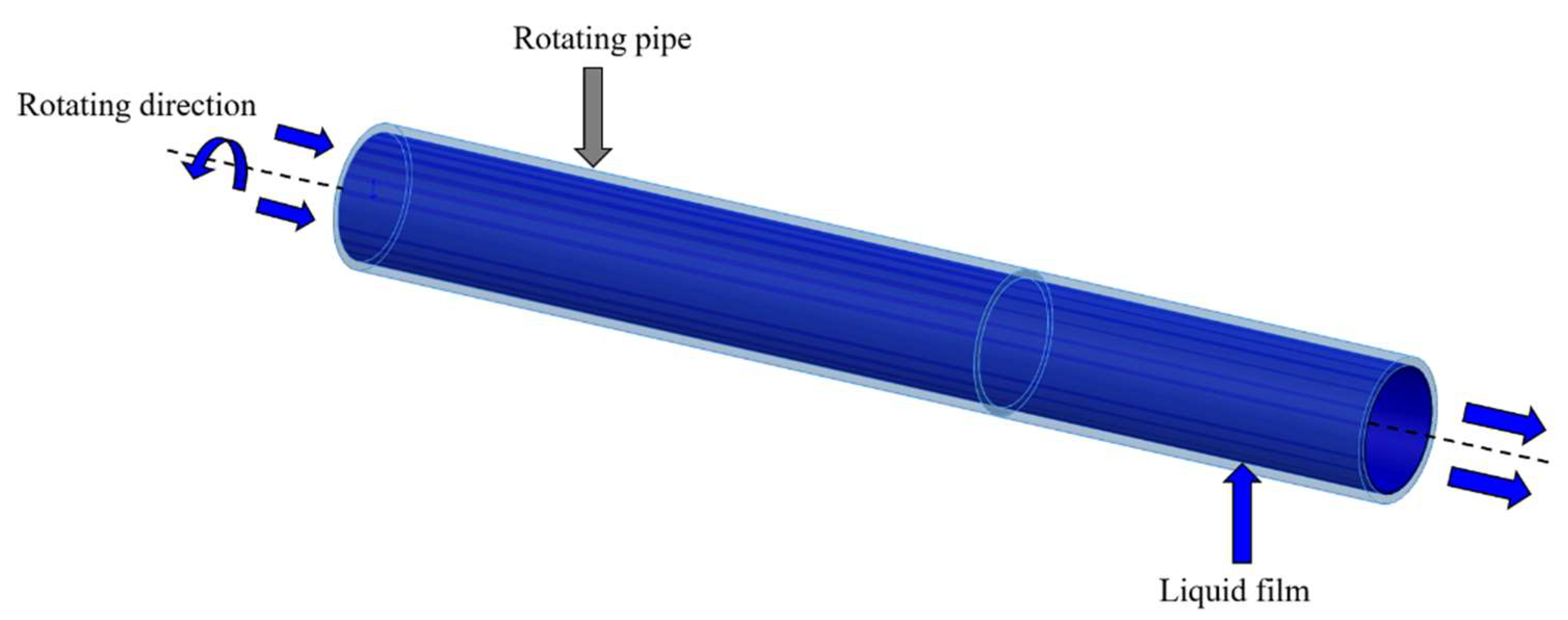
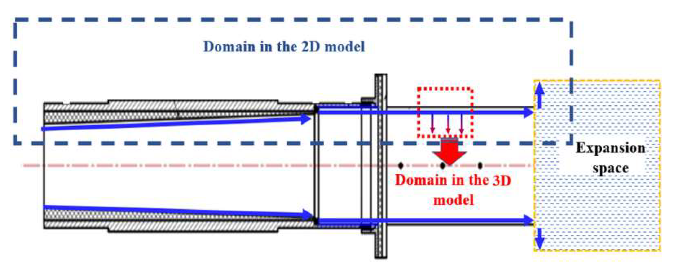
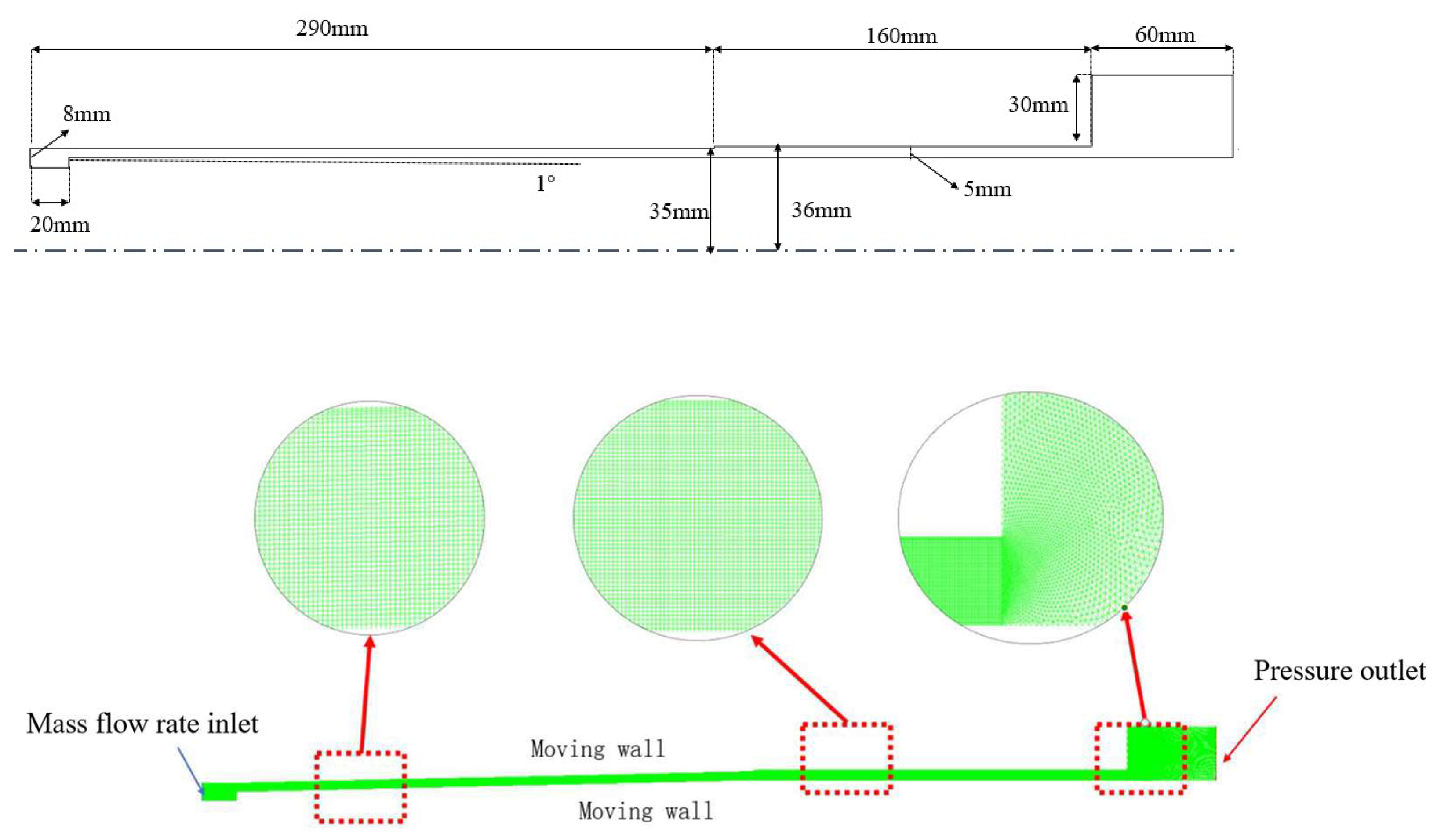
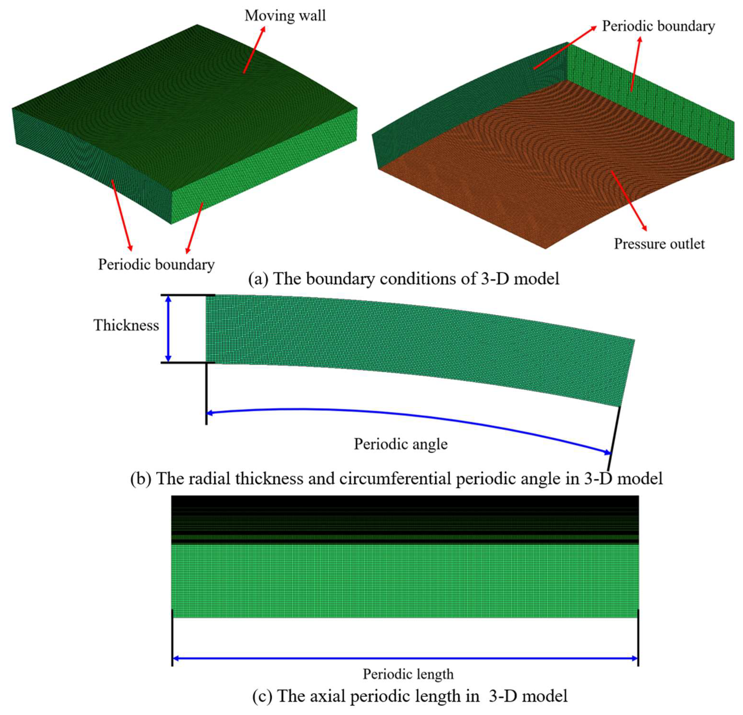
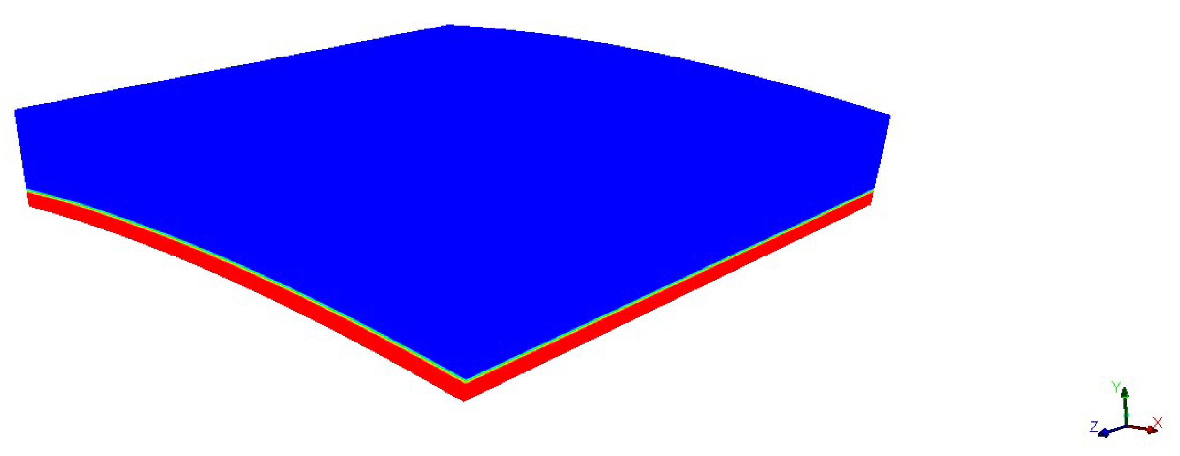
2.1. Simulation Model
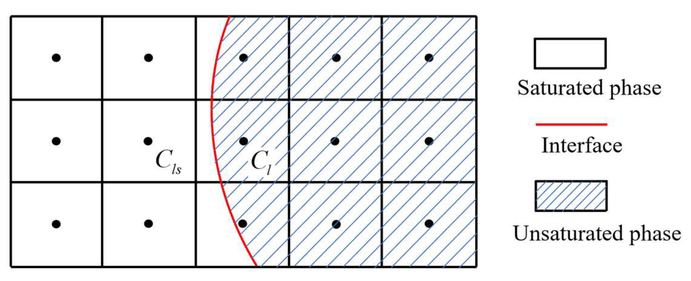
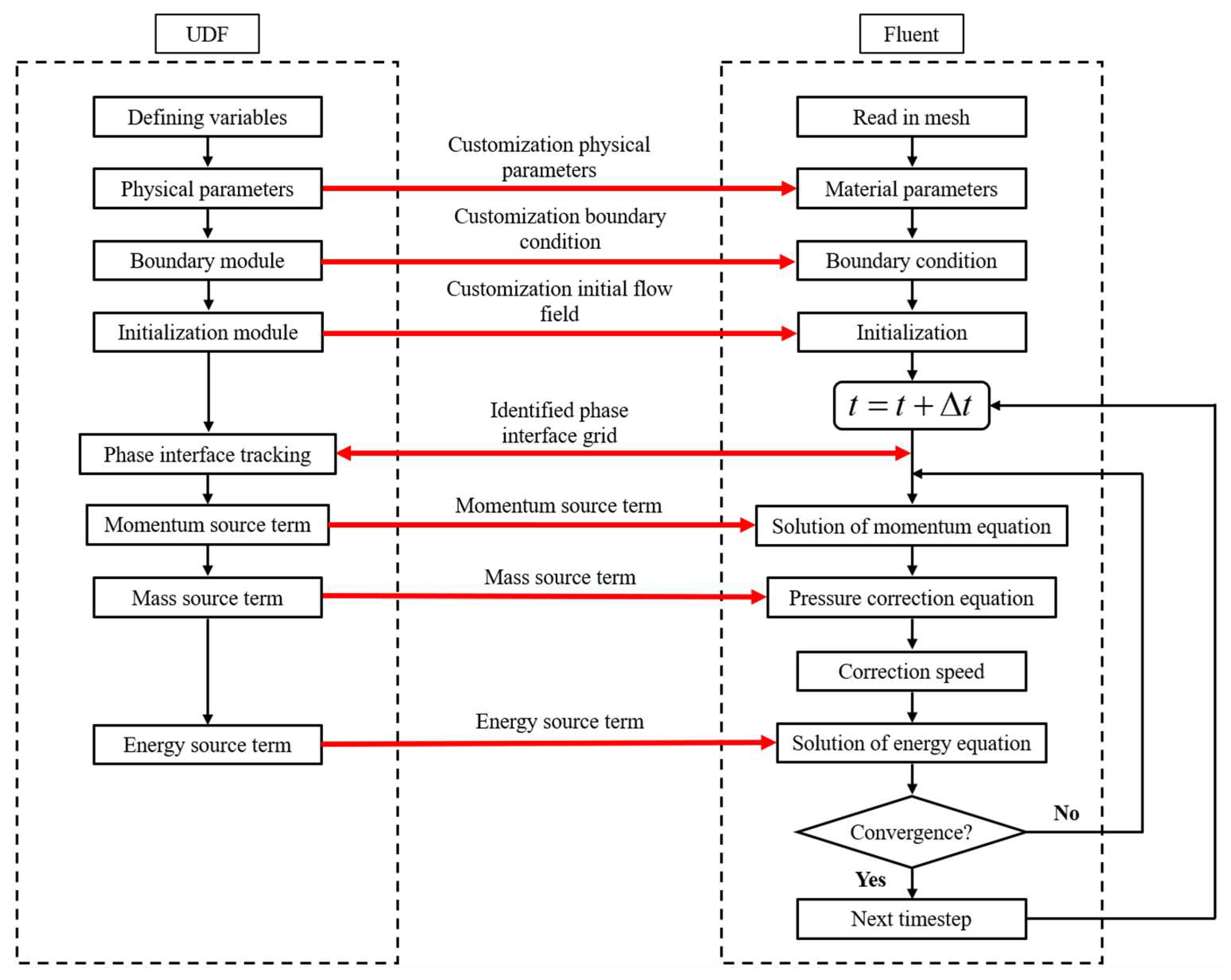
2.2. Simulation Method [10]
3. Model Validation
4. Results and Discussions
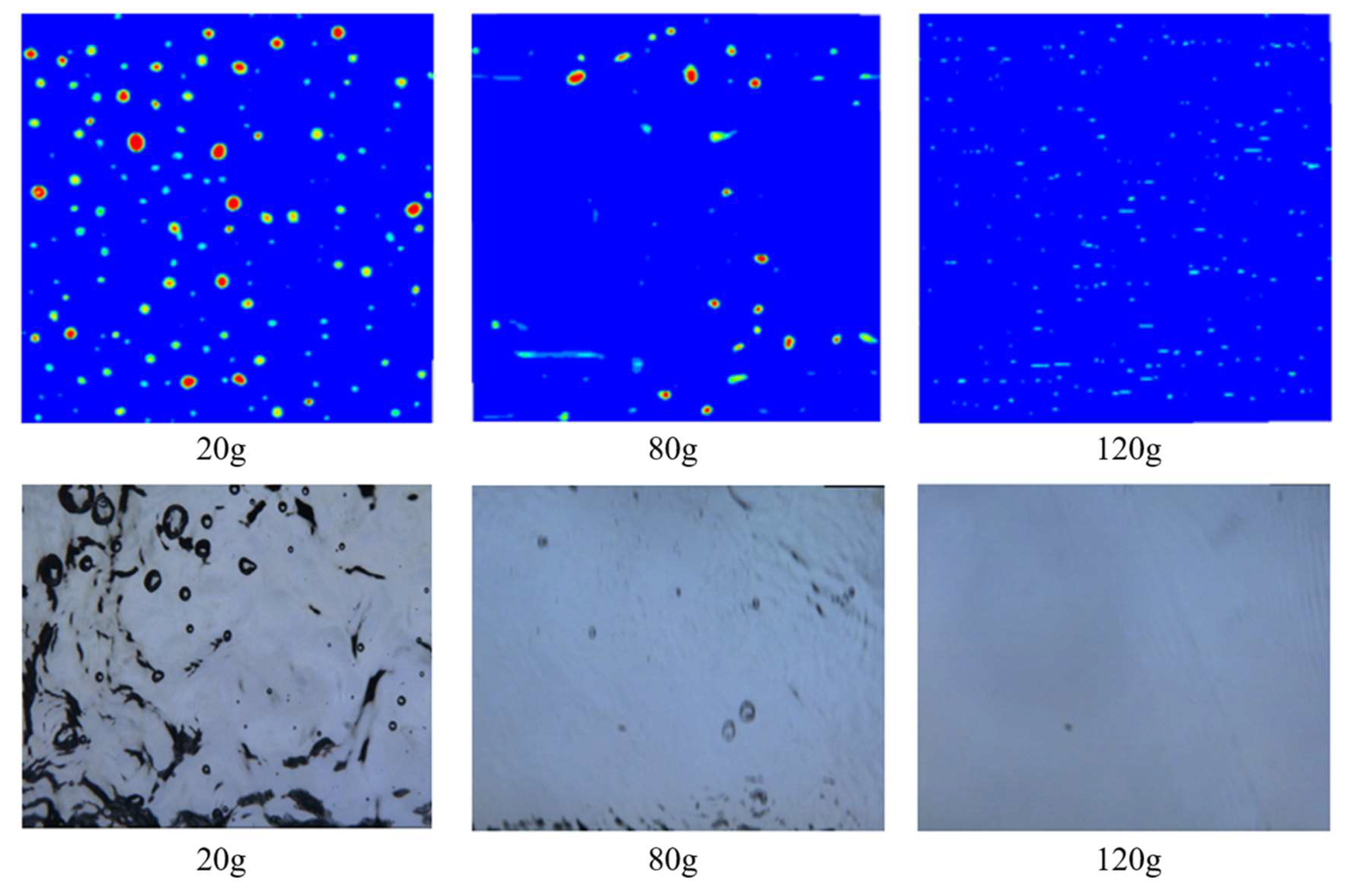
4.1. Effect of Heat Fluxes and Rotational Speeds on the Heat Transfer Characteristics
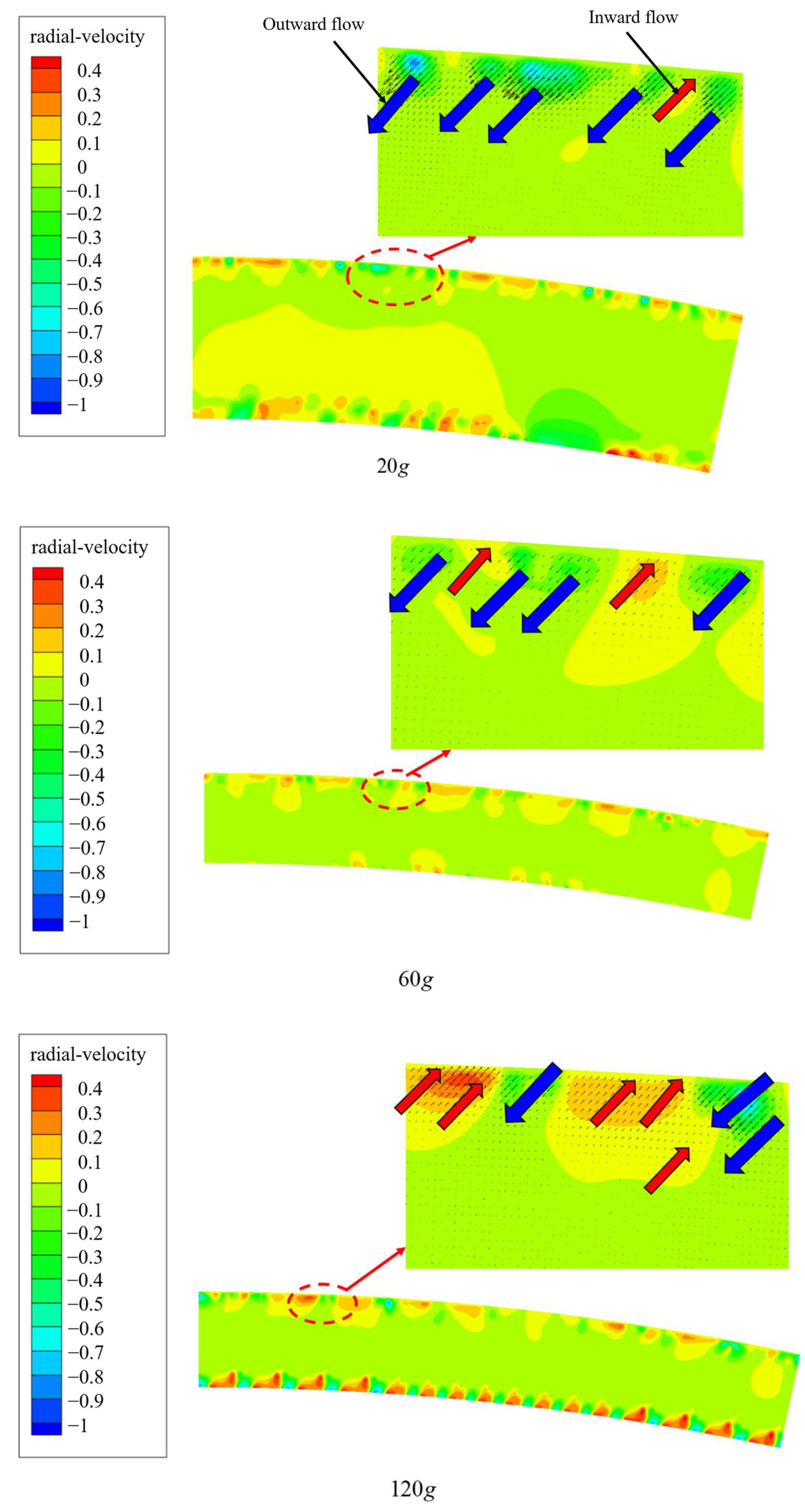
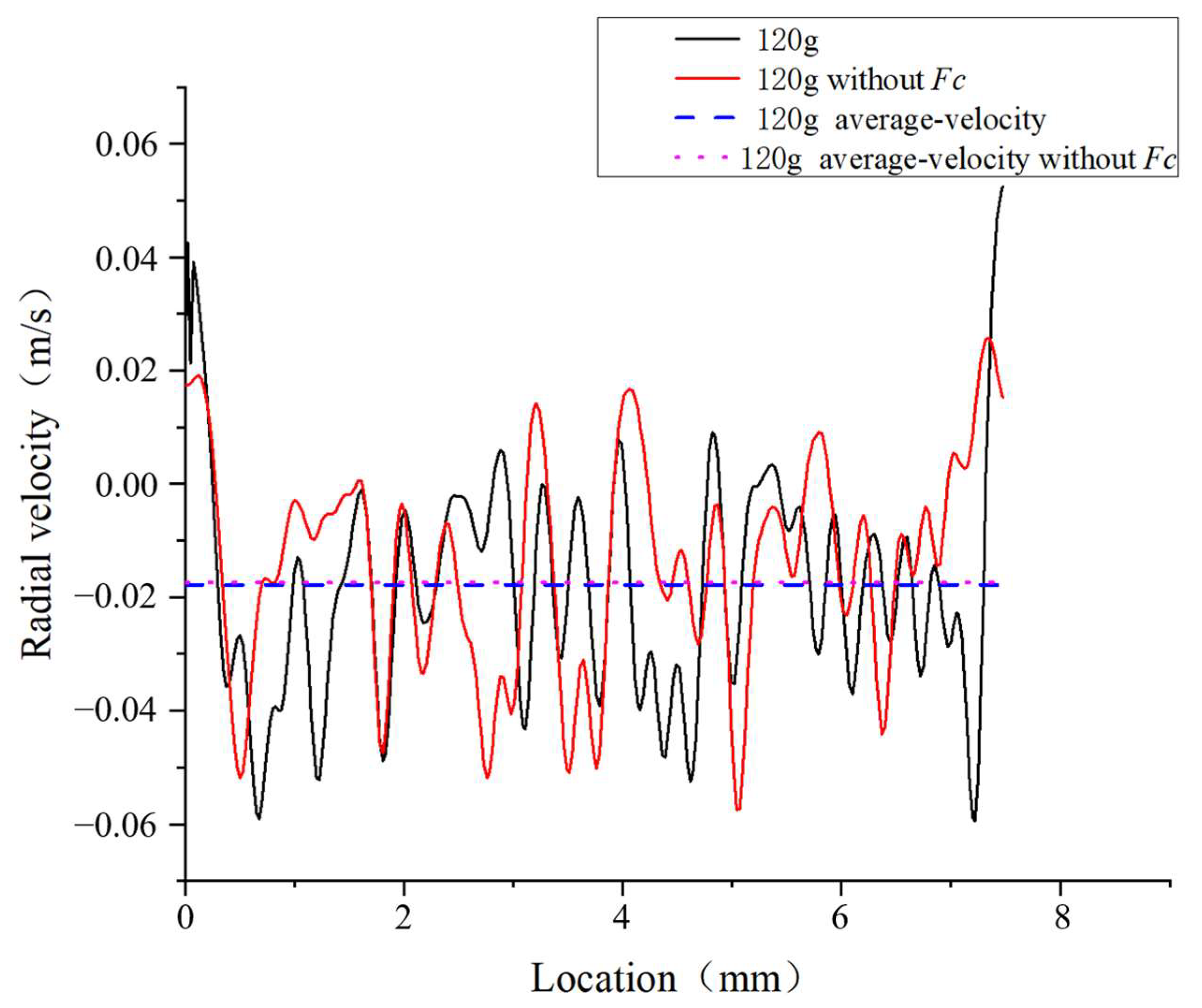
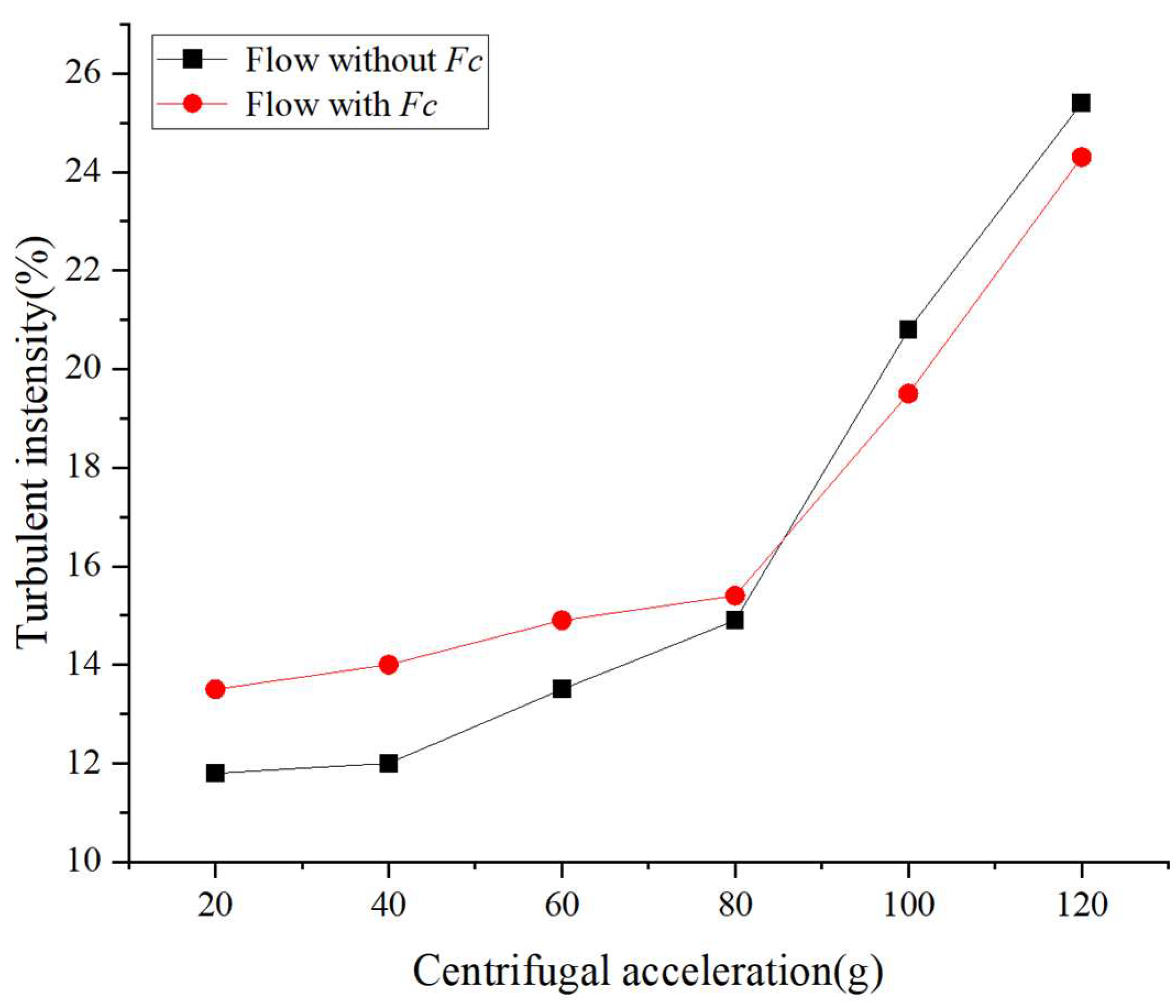
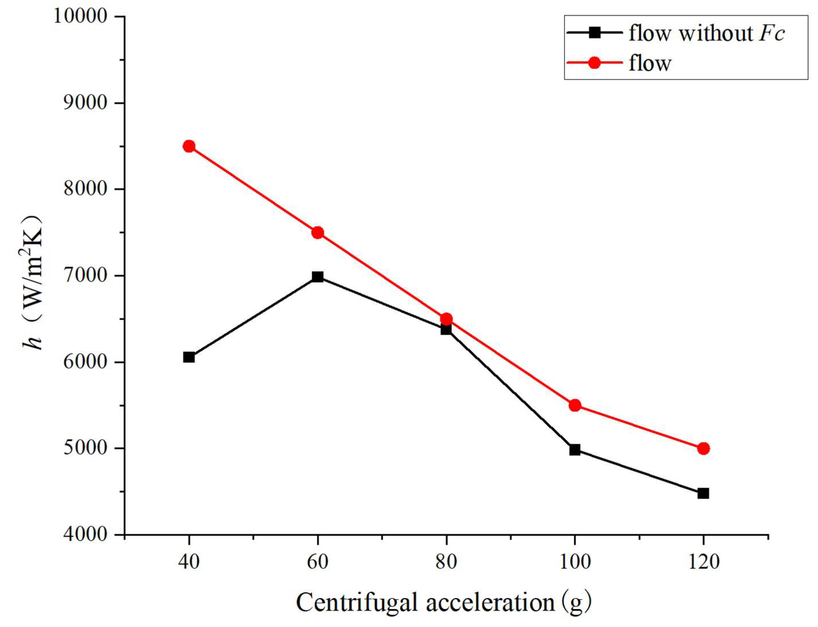
4.2. Effect of Coriolis Force on the Heat Transfer Characteristics
5. Conclusions
- (1)
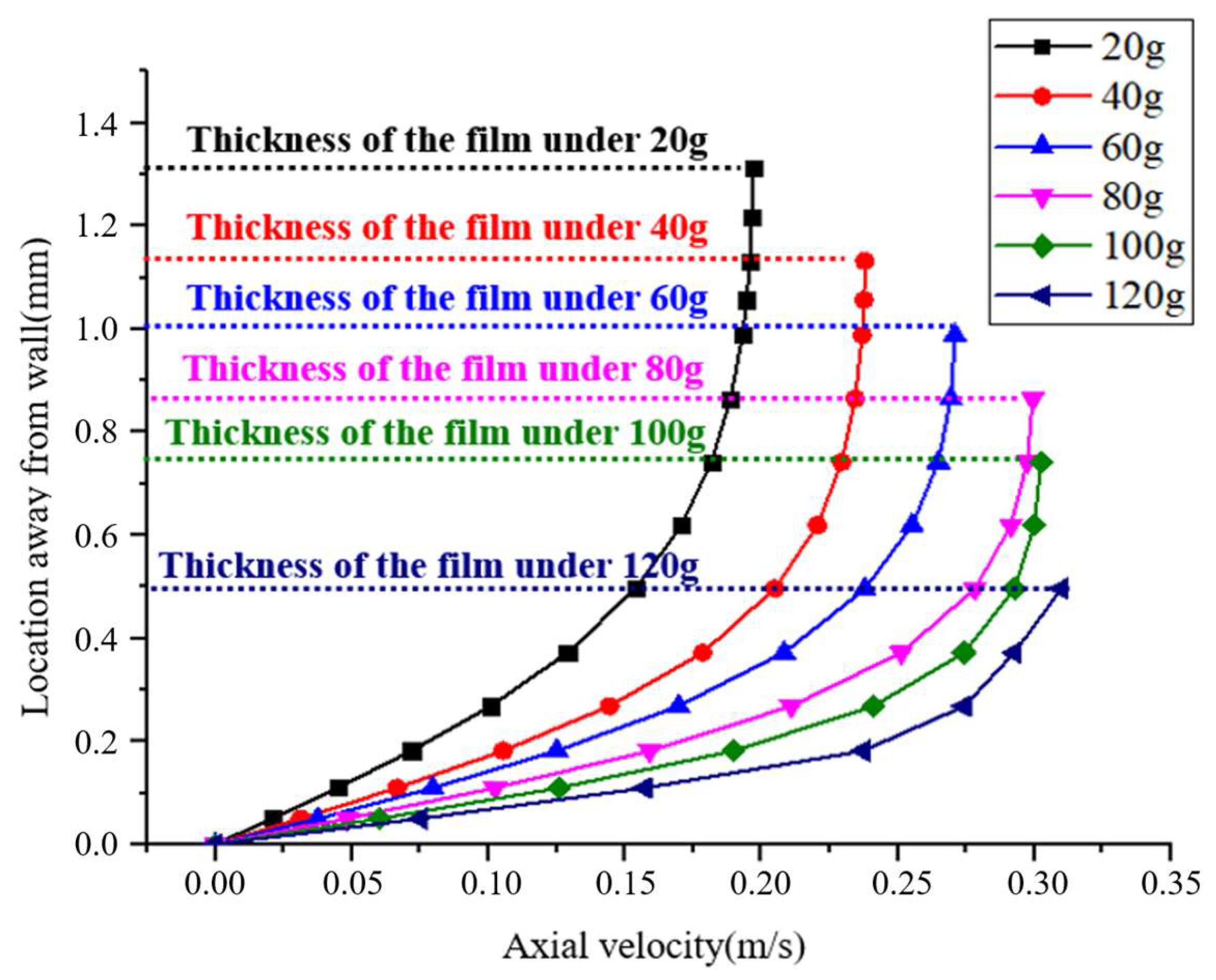
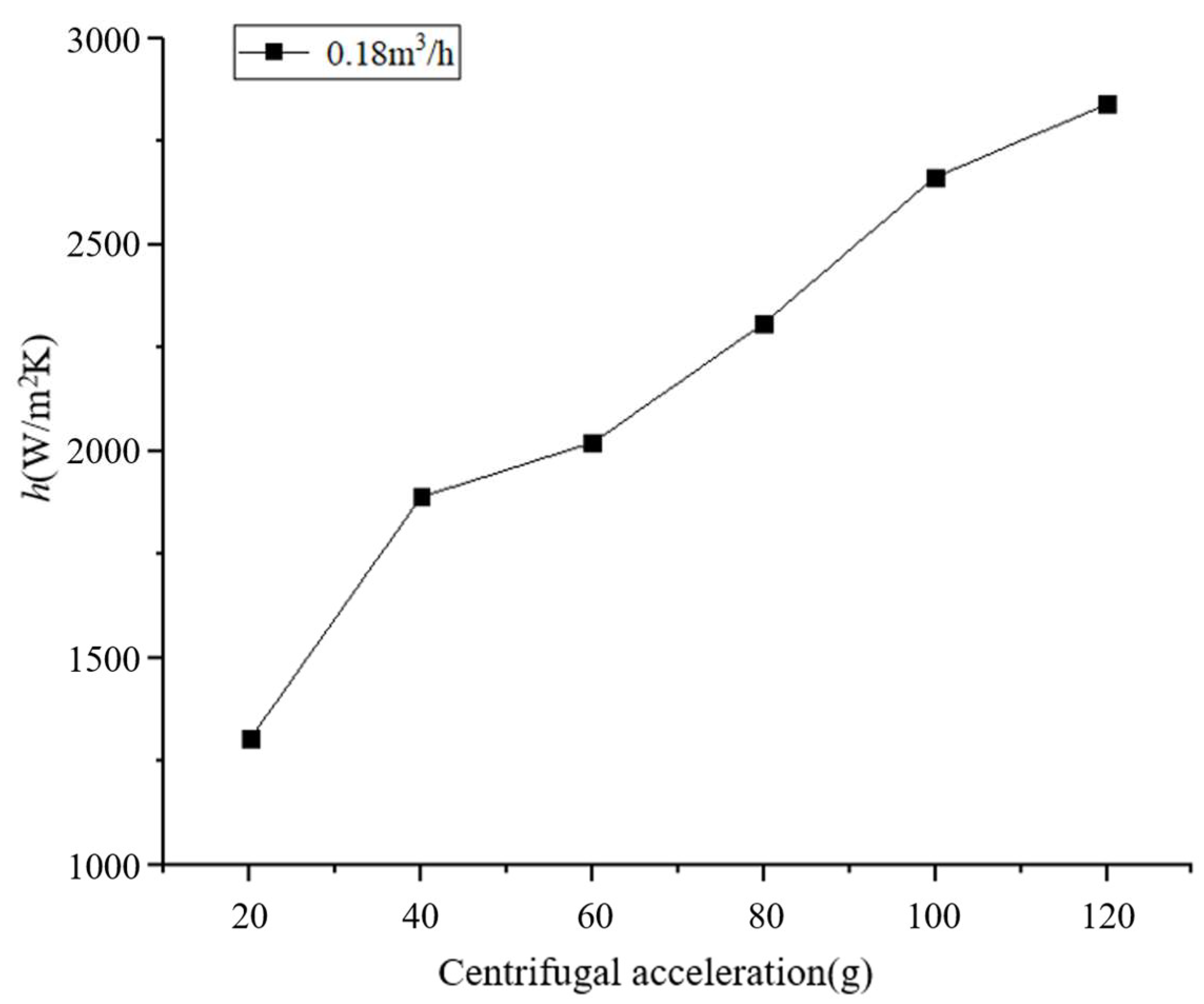
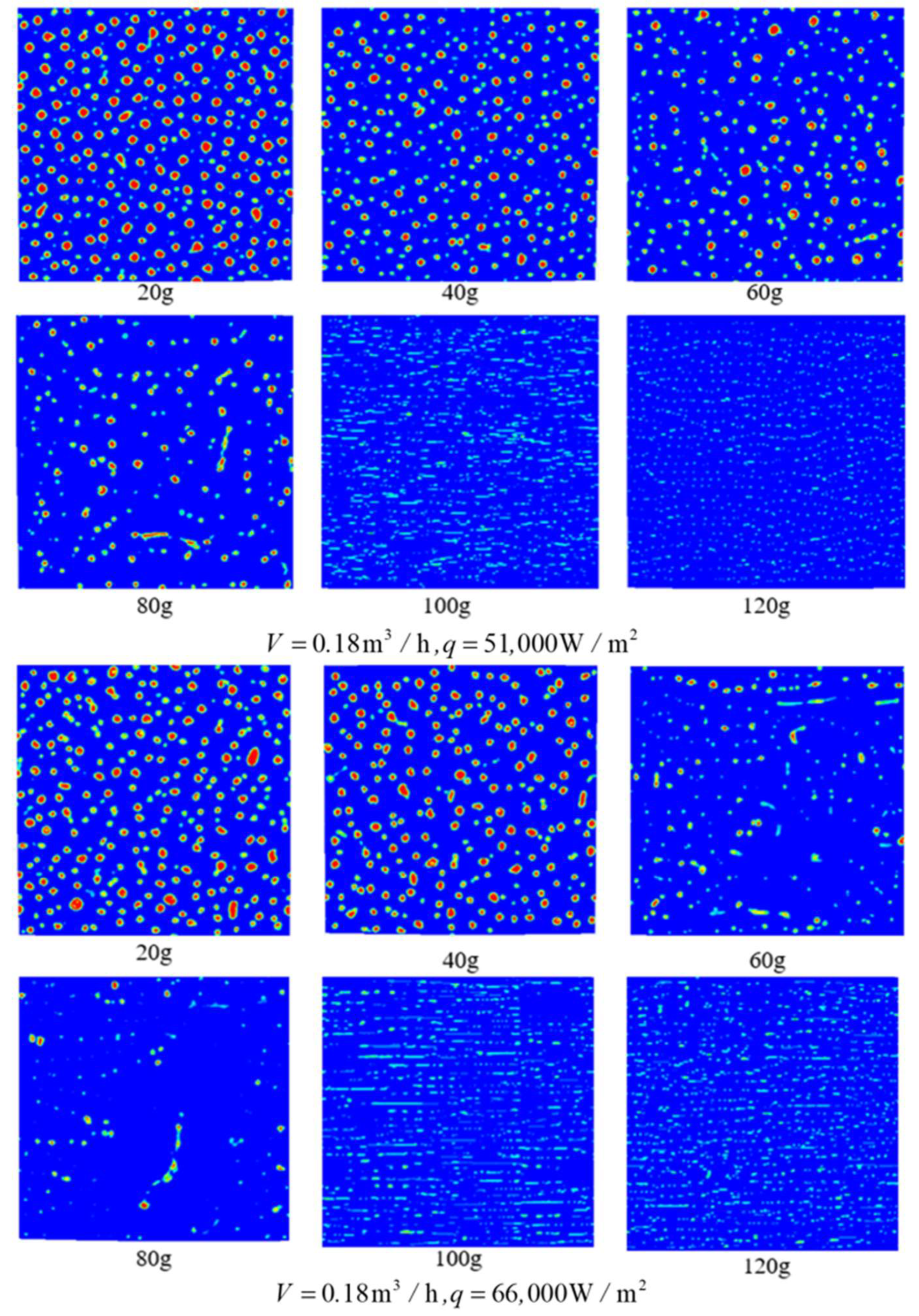
- Nuclear boiling is developed in the liquid film under low rotational speeds, and gradually suppressed as the rotational speed increases. Since the heat transfer coefficient is influenced by the convective and the boiling heat transfer, it shows an increase with the centrifugal acceleration under low rotational speeds due to the enhanced convection, and then a decrease under higher rotational speeds due to the boiling suppression.
- (2)
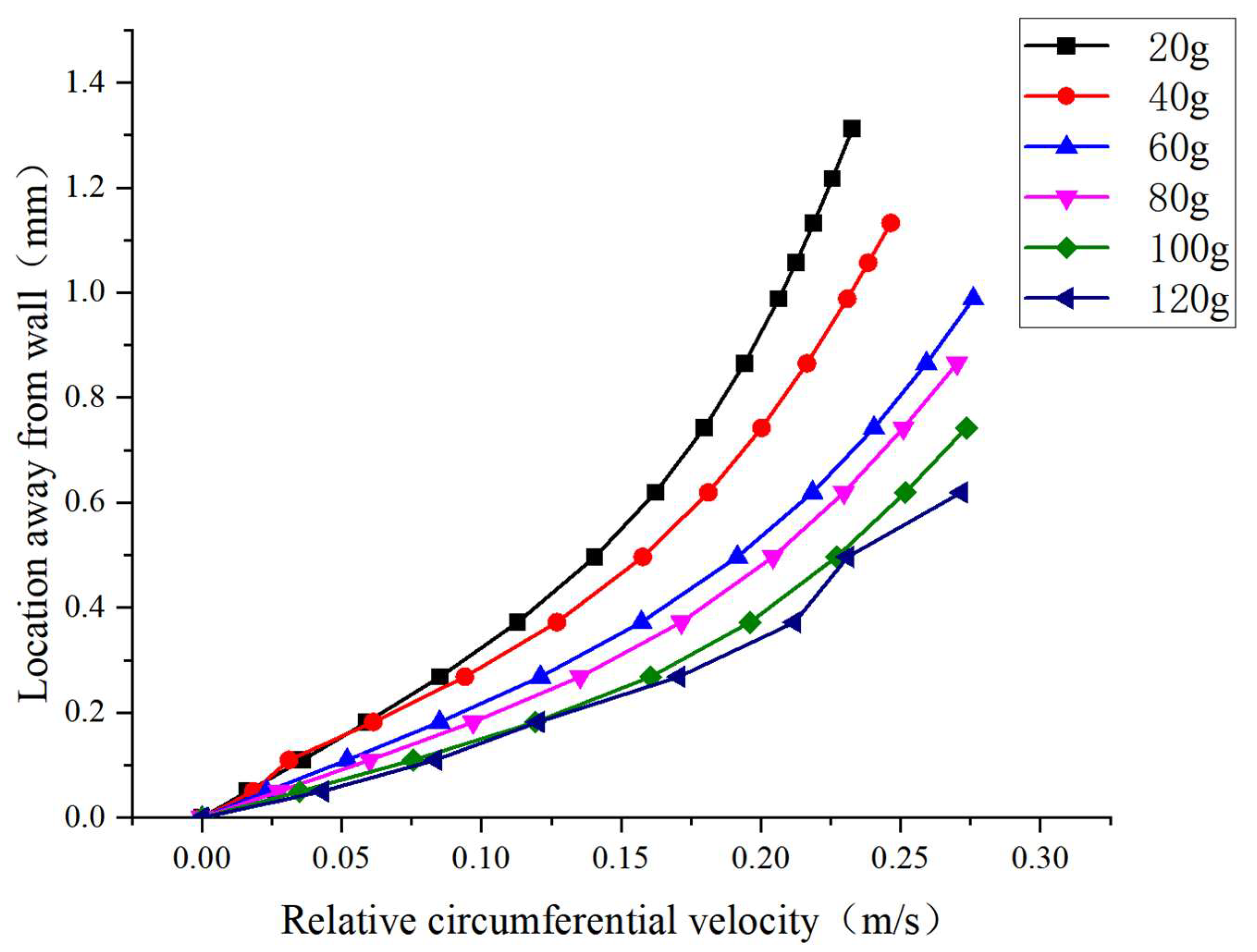
- The turbulent intensity of the flow with Coriolis force is obviously increased compared to that without Coriolis force when the centrifugal acceleration ranges from 20 g to 80 g, and a larger heat transfer coefficient is obtained when considering this force, which should not be ignored when studying the boiling heat transfer of a rotating liquid film.
Author Contributions
Funding
Institutional Review Board Statement
Informed Consent Statement
Conflicts of Interest
References
- Gray, V.H. The Rotating Heat Pipe-A Wickless, Hollow Shaft for Transferring High Heat Fluxes; NASA: Washington, DC, USA, 1969. [Google Scholar]
- Ponnappan, R.; He, Q.; Leland, J.E. Test results of a high speed rotating heat pipe. In Proceedings of the 32nd Thermophysics Conference, Atlanta, GA, USA, 23–25 June 1997. [Google Scholar]
- Li, Z. Study of a Hybrid of Pulsating Heat Pipe and Distributed Jet Array. J. Thermophys. Heat Transf. 2020, 34, 1–11. [Google Scholar]
- Brahim, T.; Jemni, A. CFD analysis of hotspots copper metal foam flat heat pipe for electronic cooling applications. Int. J. Therm. Sci. 2021, 159, 106583. [Google Scholar]
- Huang, N.L.; Luo, W.S.; Zhu, Z.J.; Bao, Y.H.; Liao, S.G. Experimental study on heat transfer performance of dual-source heat pipe air conditioning system and application. Transducer Microsyst. Technol. 2019, 38, 157–160. [Google Scholar]
- Pagliarini, L.; Cattani, L.; Bozzoli, F.; Mameli, M.; Filippeschi, S.; Rainieri, S.; Marengo, M. Thermal characterization of a multi-turn pulsating heat pipe in microgravity conditions: Statistical approach to the local wall-to-fluid heat flux. Int. J. Heat Mass Transf. 2021, 169, 120930. [Google Scholar]
- Song, F.; Ewing, D.; Ching, C.Y. Fluid flow and heat transfer model for high-speed rotating heat pipes. Int. J. Heat Mass Transf. 2003, 46, 4393–4401. [Google Scholar]
- Bertossi, R.; Guilhem, N.; Ayel, V.; Romestant, C.; Bertin, Y. Modeling of heat and mass transfer in the liquid film of rotating heat pipes. Int. J. Therm. Sci. 2012, 52, 40–49. [Google Scholar]
- Hassan, H.; Harmand, S. Effect of using nanofluids on the performance of rotating heat pipe. Appl. Math. Model. 2015, 39, 4445–4462. [Google Scholar]
- Lian, W.; Chang, W.; Xuan, Y. Numerical investigation on flow and thermal features of a rotating heat pipe. Appl. Therm. Eng. 2016, 101, 92–100. [Google Scholar]
- Lian, W.; Han, T. Flow and heat transfer in a rotating heat pipe with a conical condenser. Int. Commun. Heat Mass Transf. 2019, 101, 70–75. [Google Scholar]
- Machado, H.A.; de Miranda, R.F. Operation Limits for Rotating Cylindrical Heat Pipes. Numer. Heat Transf. 2003, 44, 299–313. [Google Scholar]
- Merte, H.; Clark, J.A. Pool boiling in an accelerating system. J. Heat Transf. 1961, 83, 233–242. [Google Scholar]
- Eschweiler, J.C.; Benton, A.M.; Prechshot, G.W. Boiling and convective heat transfer at high accelerations. Chem. Eng. Prog. Symp. Ser. 1967, 63, 66–72. [Google Scholar]
- Judd, R.L.; Merte, H., Jr. Evaluation of nucleate boiling heat flux predictions at varying levels of subcooling and acceleration. Int. J. Heat Mass Transf. 1972, 15, 1075–1096. [Google Scholar] [CrossRef] [Green Version]
- Ulucakli, M.E.; Merte, H., Jr. Nucleate boiling with high gravity and large subcooling. J. Heat Transf. 1990, 112, 451–457. [Google Scholar]
- Kurul, N. On the modeling of multidimensional effects in boiling channels. In Proceedings of the National Heat Transfer Conference, Minneapolis, MN, USA, 28–31 July 1991. [Google Scholar]
- Lee, W.H. A Pressure Iteration Scheme for Two-Phase Modeling; Technical Report LA-UR 79-975; Los Alamos Scientific Laboratory: Los Alamos, NM, USA, 1979. [Google Scholar]
- Fadhl, B.; Wrobel, L.C.; Jouhara, H. CFD Modelling of a Two-Phase Closed Thermosyphon Charged with R134a and R404a. Appl. Therm. Eng. 2015, 78, 482–490. [Google Scholar]
- Wu, H.L.; Peng, X.F.; Ye, P.; Gong, Y.E. Simulation of refrigerant flow boiling in serpentine tubes. Int. J. Heat Mass Transf. 2007, 50, 1186–1195. [Google Scholar]
- De Schepper, S.C.; Heynderickx, G.J.; Marin, G.B. Modeling the evaporation of a hydrocarbon feedstock in the convection section of a steam cracker. Comput. Chem. Eng. 2009, 33, 122–132. [Google Scholar]
- Yang, Z.; Peng, X.F.; Ye, P. Numerical and experimental investigation of two phase flow during boiling in a coiled tube. Int. J. Heat Mass Transf. 2008, 51, 1003–1016. [Google Scholar]
- Goodson, K.; Rogacs, A.; David, M.; Fang, C. Volume of fluid simulation of boiling two-phase flow in a vapor-venting microchannel. Front. Heat Mass Transf. 2010, 36, 1–11. [Google Scholar]
- Sun, D.; Xu, J.; Chen, Q. Modeling of the Evaporation and Condensation Phase-Change Problems with FLUENT. Numer. Heat Transf. Part B Fundam. 2014, 66, 326–342. [Google Scholar]
- Peterson, G.P. An Introduction to Heat Pipes; John Wiley& Sons, Inc.: New York, NY, USA, 1994. [Google Scholar]
- Zhao, P.; Ji, W.; Zhao, E.; He, Y.; Tao, W. Study on the pool boiling heat transfer of surfaces with different wettability. China Sci. 2018, 13, 1211–1216. [Google Scholar]


| Volume Flow Rate (V) | 0.18 m3/h |
|---|---|
| Heat flux (q) | 44,000 W/m2 |
| 51,000 W/m2 | |
| 66,000 W/m2 | |
| Rotational speed (ω) | 73.7 rad/s (a = 20 g) |
| 104.34 rad/s (a = 40 g) | |
| 127.8 rad/s (a = 60 g) | |
| 147.57 rad/s (a = 80 g) | |
| 164.99 rad/s (a = 100 g) | |
| 180.74 rad/s (a = 120 g) | |
| Working medium | water |
Publisher’s Note: MDPI stays neutral with regard to jurisdictional claims in published maps and institutional affiliations. |
© 2022 by the authors. Licensee MDPI, Basel, Switzerland. This article is an open access article distributed under the terms and conditions of the Creative Commons Attribution (CC BY) license (https://creativecommons.org/licenses/by/4.0/).
Share and Cite
Lian, W.; Zhu, Y.; Sun, Z. Study on the Flow Boiling Heat Transfer Characteristics of the Liquid Film in a Rotating Pipe. Energies 2022, 15, 6279. https://doi.org/10.3390/en15176279
Lian W, Zhu Y, Sun Z. Study on the Flow Boiling Heat Transfer Characteristics of the Liquid Film in a Rotating Pipe. Energies. 2022; 15(17):6279. https://doi.org/10.3390/en15176279
Chicago/Turabian StyleLian, Wenlei, Yu Zhu, and Zijian Sun. 2022. "Study on the Flow Boiling Heat Transfer Characteristics of the Liquid Film in a Rotating Pipe" Energies 15, no. 17: 6279. https://doi.org/10.3390/en15176279
APA StyleLian, W., Zhu, Y., & Sun, Z. (2022). Study on the Flow Boiling Heat Transfer Characteristics of the Liquid Film in a Rotating Pipe. Energies, 15(17), 6279. https://doi.org/10.3390/en15176279