1. Introduction
The gradual depletion of fossil fuels has driven research into renewable resources [
1]. Many countries have made progress in promoting renewables within their energy mix, but obstacles remain, and further efforts are needed. Making a renewable system reliable over time requires provision from storage systems to avoid gaps in energy supply [
2]. Energy storage is a key determinant in the energy transition process. Energy storage systems provide greater accessibility to renewable energy sources in the power grid, ensuring both energy savings and reduced impact on the environment [
3,
4], while reducing the gap between energy supply and demand [
5]. The advantages offered by storage systems include increased stabilization of energy supply that can cope with high- and low-demand scenarios, relief of consumer bills by reducing and shifting peak electricity demand, and improved grid resilience [
6].
The energy stored can be generated from a system (active storage) or can be stored passively in materials exploiting climatic fluctuations. In the latter case, some materials can store the solar energy directly in the building’s walls using a sensible or latent process, i.e., with traditional or phase-change materials (PCMs) [
7]. By the same principle, thermal solar energy can be stored in tanks integrated with PCMs to decrease the tank discharge time [
8].
The classification of active storage systems can be made by considering the form of secondary energy in which the primary energy is stored.
In electrical energy storage systems (EESSs), electrical energy is converted into other types of potential energy, such as chemical, mechanical, elastic, and magnetic energy. Among them are the following:
Electrochemical storage, which includes lead–acid and nickel–cadmium batteries;
Mechanical energy storage, such as compressed-air energy storage (CAES);
Electrical storage, such as supercapacitors or superconducting magnetic energy storage (SMES);
Hydrogen storage coupled with fuel cells for its reconversion into electrical energy [
9,
10].
Although the importance of storage systems for energy efficiency is widely recognized, the range of energy storage techniques for microscale applications is very limited, and some mechanical and thermal energy storage systems include those that are applied in the high-power generation sector. In addition to being expensive [
11], storage systems are often oversized [
12], and their disposal and average lifespan are also challenging [
13].
Electrochemical storage is currently the state of the art for small-scale energy storage. However, batteries are not yet considered to be a fully mature technology either technically or economically. The most promising technology—namely, the lithium-ion battery—depends on a strategic material that has limited uptake and is currently not recycled for economic reasons. However, in addition to cost reduction, technological improvements will also need to address increasing the specific energy and lifetime of storage batteries.
CAES technology enables the trigeneration of electrical, thermal, and cooling energy in the energy release process. Specifically, trigeneration systems simultaneously provide heat, power, and cooling using a single fuel source. Compared with conventional systems, cogeneration and trigeneration systems reduce fossil fuel demand and grid losses [
14].
The trigeneration system of electrical, thermal, and refrigeration energy allows excess energy to be stored in the form of compressed air and thermal heat, and enables refrigeration energy to be produced through the direct expansion of compressed air. Modeling of compressed-air energy storage systems considering network-specific requirements has shown that optimal design leads to improved functionality and an overall reduction in system costs [
15]. CAES systems provide several advantages over other storage systems, including high power and energy capacity, long service life, rapid response, and relatively low capital and maintenance costs [
16].
CAES can be integrated with renewable energy systems, such as wind and solar power. This allows excess energy from renewable sources to be stored, effectively addressing the fluctuation of renewable sources (i.e., avoiding curtailment) [
17]. Several articles in the literature have provided an overview of CAES in terms of scale, fuel utilization, and integration with other technologies (e.g., smart grid and energy internet), emphasizing its potential applications [
18,
19]. Wang et al. presented a discussion of the challenges and prospects of using CAES systems [
20]. CAES is considered to be the most cost-effective technology, as well as being excellent for its scalability and ease of implementation when used on a utility scale [
21].
Today, CAES is mainly used on a large scale (i.e., macro-CAES)—compressed air is stored, during the hours when the cost of energy is lowest, inside hermetically sealed underground cavities and at pressures generally around 70–100 bar; the same high-pressure gas is used in traditional turbo gas systems, or for pneumatic drives in production lines for a wide variety of needs and for automation in general. These systems have a good energy density—typically around 2–3 kWh/m3 of storage, which is almost 10 times higher than the energy density of mechanical gravity storage used in hydroelectric power plants.
A potentially viable alternative to electrochemical systems for small-scale storage is micro-CAES. Among the main advantages of micro-CAES coupled with TES (thermal energy storage) is the possibility of recovering waste energy to make the micro electric generation system more competitive. The heat developed during the compression phase can be used for residential heating and/or domestic hot water production, while the expanding cold air can be used for space cooling.
The potential advantages of micro-CAES systems are as follows:
- −
Longer life than batteries, allowing a potentially unlimited number of charge and discharge cycles;
- −
High sustainability, as they do not require the use of toxic or rare chemicals;
- −
Flexibility in operation and installation, allowing micro-CAES to operate independently or in connection with the power grid, or even in combination with storage batteries.
Applications of small-scale CAES systems are not currently widespread. One reason that residential micro-trigeneration and trigeneration have received much less attention than large-scale systems is that small-scale applications provide a cooling load through a reverse Rankine cycle that requires high capital cost components, such as absorption chillers and boilers, to cool the load [
22].
Cogeneration and trigeneration systems can operate more efficiently if electricity and heat production are decoupled using thermal energy storage, where unneeded heat is stored during the production period [
23]. Achieving a highly feasible CAES system enables the design of a flexible energy system characterized by the optimal use of fluctuating renewable energy sources [
24]. Different numerical and thermodynamic analyses have been conducted in the literature to highlight and evaluate the applicability of CAES systems [
25,
26]. Solutions to improve CAES systems’ performance have been proposed as a result of optimization analyses [
27]. Luo et al. [
28] proposed a modeling and simulation tool for A-CAES (adiabatic compressed-air energy storage) system optimization to identify heat exchange and thermal storage units with suitable capacity and performance for air compression/expansion units, and then analyze system efficiency and identify potential improvement strategies.
Considering that the above, energy storage techniques for microscale applications are still very limited—especially micro-CAES applications. This study proposes an optimization of mechanical and thermal storage systems for small-scale trigeneration. The objectives are to identify solutions that are economical (e.g., components with affordable costs, technologies easily available on the market, and minimal maintenance) and adaptable to the spaces generally available in the residential area.
The present work is an extension of previous works [
29,
30]; the system is designed for a single-family residential building equipped with a photovoltaic system with a rated power of 3 kW.
First, this paper presents the case study to which the optimization for a mechanical and thermal storage system for small-scale trigeneration is applied. The purpose of the optimization was to improve the efficiency of the micro-CAES + TES system, along with attempting to simplify the structure as much as possible to make it economical and suitable for residential spaces. Finally, a comparison with the use of battery storage systems was conducted.
2. The Case Study: Micro-CAES for Trigeneration
The micro-CAES + TES system is designed for a single-family residential building equipped with a photovoltaic system with a nominal power of 3 kW. The average electricity demand of a family can be estimated at about 3000 kWh/year which, divided daily, becomes about 8.2 kWh/day. Assuming that at least 50% of household consumption takes place in the evening or at night when the photovoltaic system does not produce energy, about 4 kWh/day must be accumulated to have a good margin of autonomy from the grid. Therefore, on a typical day, the photovoltaic system can produce for immediate daytime consumption, or alternatively for night-time consumption by loading the mechanical storage system so that it can be discharged for the night.
The operation, as in any other storage technology, is divided into two phases deferred in time according to the time-shifting of the electricity demand of domestic users—a charging phase of the CAES’s compressed air tank, with electricity absorption to the compressor, followed by a discharge phase of the same CAES tank with electricity generation to the expander. During the charging phase, the CAES system accumulates photovoltaic electrical energy in the form of energy elastic mechanics in the storage tank. At the same time, the HTTES (high-temperature thermal energy storage) system is also charged with the heat transfer fluid which, moving in a specially designed secondary circuit, recovers the thermal waste from the compression. During the discharge phase, the elastic energy is again converted into electrical energy using a turbine connected to the alternator. At the same time, the LTTES (low-temperature thermal energy storage) system is charged through the expanded cold air that cools the heat transfer fluid, which moves in its secondary circuit (distinct from that of the HTTES system). The heat developed during the compression phase can be used for residential heating and/or domestic hot water production, while the expanded cold air can be used for room cooling.
The problem is initially analyzed from a thermodynamic point of view. When filling the storage tank, the compressor sucks in atmospheric air and processes it to raise the storage pressure from the minimum operating value to the maximum. This process is non-stationary, and the type of compressor chosen must have suitable characteristics to keep the processed flow rate as constant as possible as the compression ratio varies. From this point of view, the best-performing compressors are the alternatives, which also offer a wide pressure range, long life, easy maintenance, and high reliability.
The choice of the type of expander, on the other hand, falls on the pneumatic reed motor as a technology widely used on the market and at affordable prices. It is chosen to power a motor with a nominal power of 5 kW with compressed air at 5 bar, obtaining a mechanical power of 3.85 kW on the shaft.
In this study, the aim was to optimize a micro-CAES system powered by a photovoltaic solar system with a nominal power of 3 kW for a domestic user, to which an electrical power of 3 kW was allocated through a pneumatic reed motor powered constantly at 5 bar. The CAES was combined with a high-temperature TES system for the recovery of thermal compression waste, which took place through a reciprocating volumetric compressor, and a low-temperature TES system for the recovery of the cooling capacity of the expanded air.
3. Optimization Setup
The goal of optimization is to maximize efficiency measures for mechanical and thermal storage. The charging and discharging processes of the micro-CAES were analyzed from a thermodynamic point of view to obtain the equations governing the problem in a previous study [
29]. These equations were implemented in MATLAB and optimized with modeFRONTIER software.
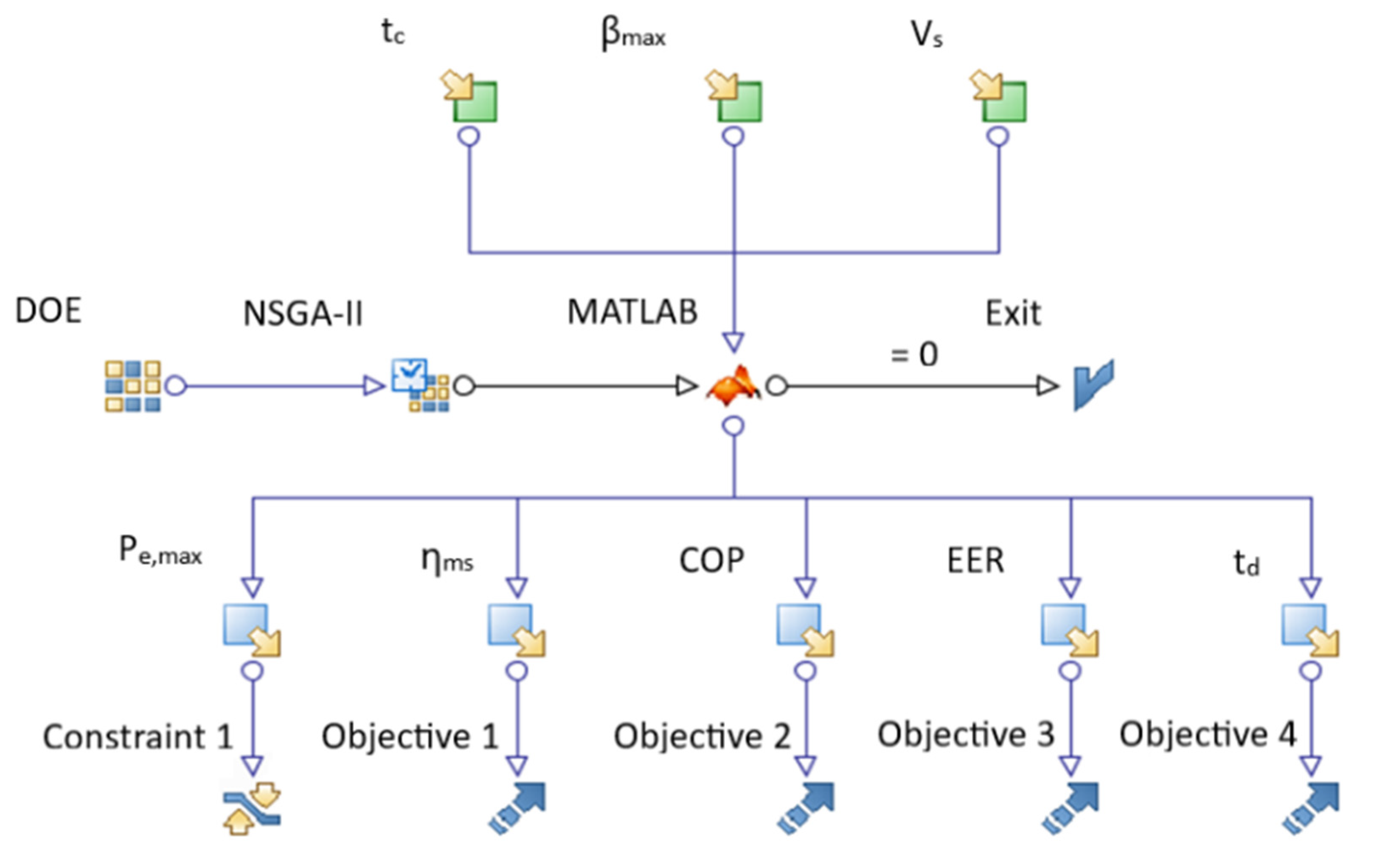
Figure 1 shows the workflow of the optimization problem carried out in modeFRONTIER. The inputs, outputs, and constraints applied to the optimization model are described in detail in the following paragraphs (
Section 3.1 and
Section 3.2).
In the workflow, the first set of DOE (design of experiments) is a random sequence. The chosen NSGA-II (non-dominated sorting genetic algorithm II) optimization algorithm is an evolutionary algorithm suitable for solving optimization problems with multiple objectives [
31,
32].
3.1. Inputs
The thermodynamic equations were implemented in the MATLAB environment. Several operational coefficients and parameters were established in the preliminary analysis, as shown in
Table 1.
The optimization analysis was based on the variation, within a fixed range, of the parameters shown in
Table 2. By simulating the variables in appropriate ranges, it is possible to obtain, among all possible combinations, those that optimize the predetermined objectives.
For the maximum compression ratio () the lower limit of 10 was chosen, since for pressures below 10 bar the air compression has insignificant temperature variations, which would not justify the installation of the HTTES system. The upper limit, on the other hand, was taken to be 35, because the datasheets of manufacturers of reciprocating compressors show that with a maximum installed motor power of 3 kW (equal to the nominal power of the photovoltaic system) it is possible to compress air up to a maximum of 35 bar. The storage volume of the compressed air () had an upper limit of 10 m3 for space and cost reasons. Finally, the duration of the charging phase of the CAES () must be consistent with the hours during which the solar photovoltaic system can operate during the day; for this reason, the upper limit of 5 h was set. The possible values assigned to each input variable result in up to 300 different experiments to be conducted.
3.2. Outputs
The storage efficiency of the system was optimized from both the mechanical and the thermal points of view. For the CAES system, the final purpose is electrical generation; the efficiency of mechanical energy storage (
) is defined as the ratio between the electrical energy generated during the discharge phase
and the electrical energy spent on the compressor during the charging phase
.
For the HTTES system, the final purpose is the recovery of the thermal waste from the compressor, for which the coefficient of performance (COP) in calorific storage is defined as the ratio between the thermal energy stored in the system
and the net electrical energy spent for storage
.
For the LTTES system, the final purpose is the recovery of cooling capacity, so the energy efficiency ratio (EER) in refrigerated storage is defined as the ratio between the cooling capacity stored in the system
and the net electrical energy spent to produce it
.
For all three systems, the maximum electrical power consumption
was constrained, as shown in
Table 3.
For the CAES, the discharge time
was maximized.
where
is the mass stored during the charging process and
represents the mass flow rate of expanded air processed by the turbine [
29].
The study of the optimization of the micro-CAES + TES system is not limited to simply maximizing the accumulation efficiency parameters; it is also necessary to combine other requirements that arise from the installation of such a system within a home unit, as follows:
Reduce the space occupied by the facility, with particular reference to the CAES tank, which is the bulkiest element;
Simplify the structure as much as possible to make it economical to purchase and maintain;
Limit the maximum operating pressures to ensure greater safety;
Power the households as long as possible so that the system is functional even in the evening hours when the PV system is not producing energy.
4. Results
The results show that of the 300 experiments generated, less than 34% meet the constraints imposed by the workflow. Unacceptable solutions were discarded from the design space table.
Figure 2 and
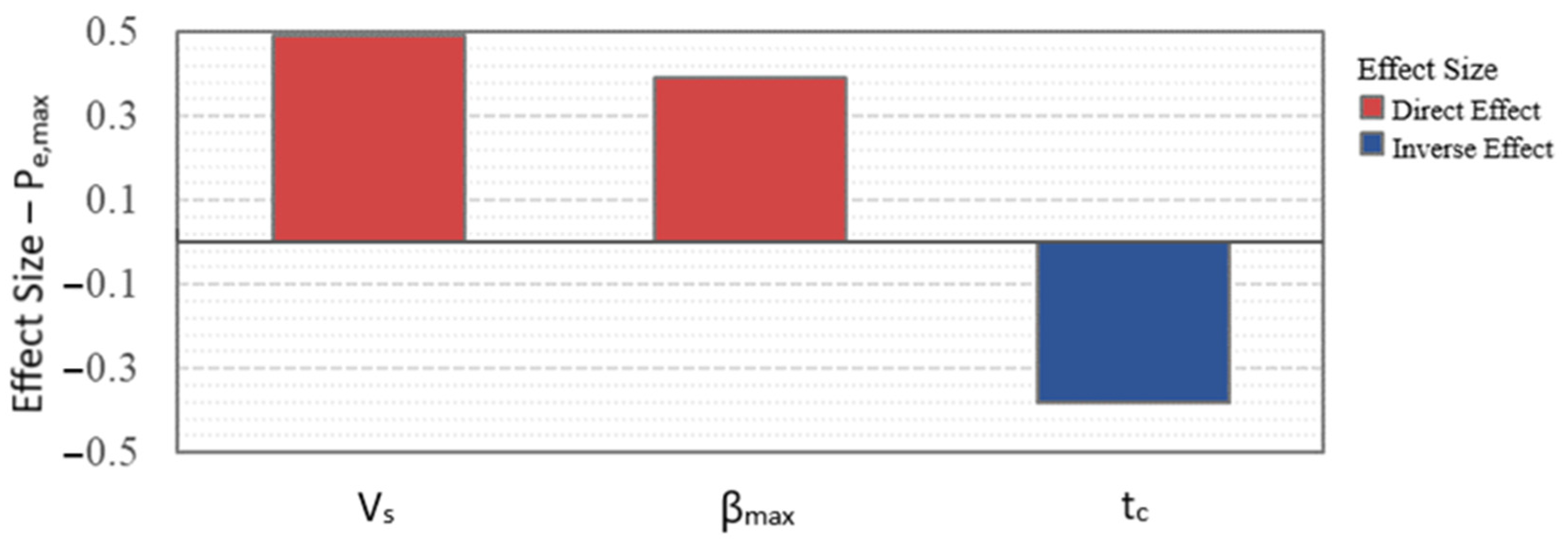
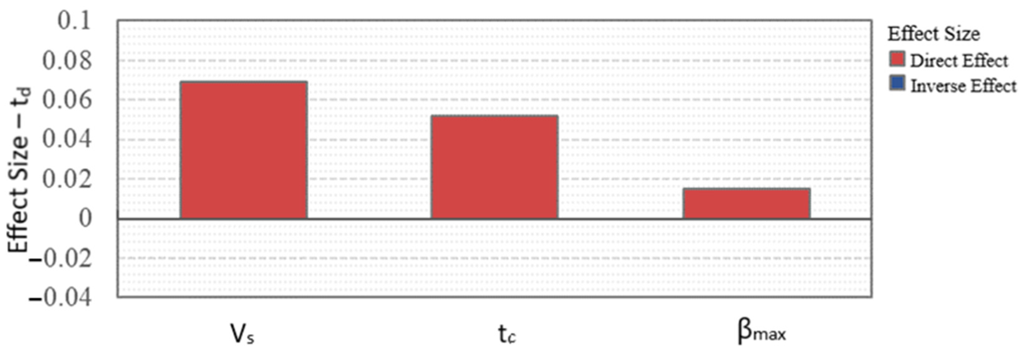
Figure 3 provide an estimation of the relationships between input and output factors. A positive value (red bar) indicates a direct relationship, while a negative value (blue bar) indicates an inverse relationship. In particular,
Figure 2 represents the correlation between the maximum power absorbed by the compressor
and the input variables
while
Figure 3 shows the correlation between the CAES discharge time
and the input variables.
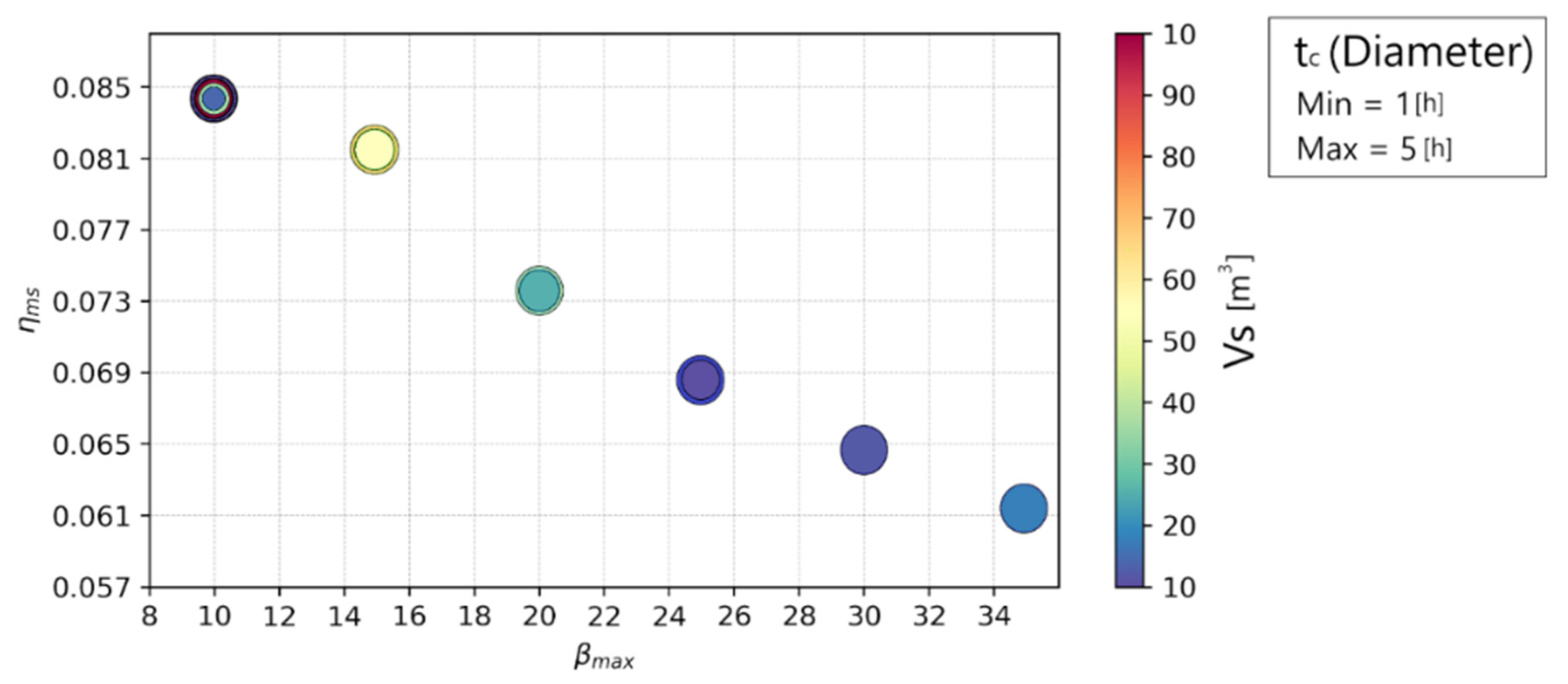
To present the relationship between the mechanical energy storage efficiency
and the input variables, a 4D bubble chart (
Figure 4) was used. This is particularly useful because it allows the values obtained from optimization for the four variables to be shown. In particular, the x and y axes represent
and
, respectively, while the diameter indicates the
and the color indicates the
.
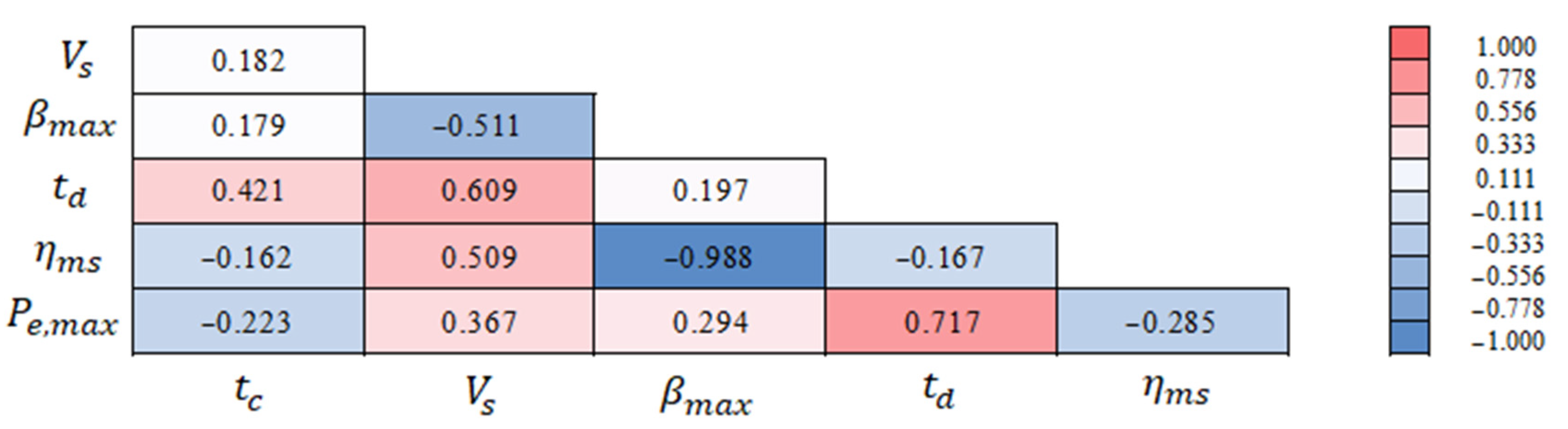
The correlation matrix (
Figure 5) summarizes all of the relationships concerning the mechanical accumulation system between the input factors (
,
,
) and the output variables (
,
,
).
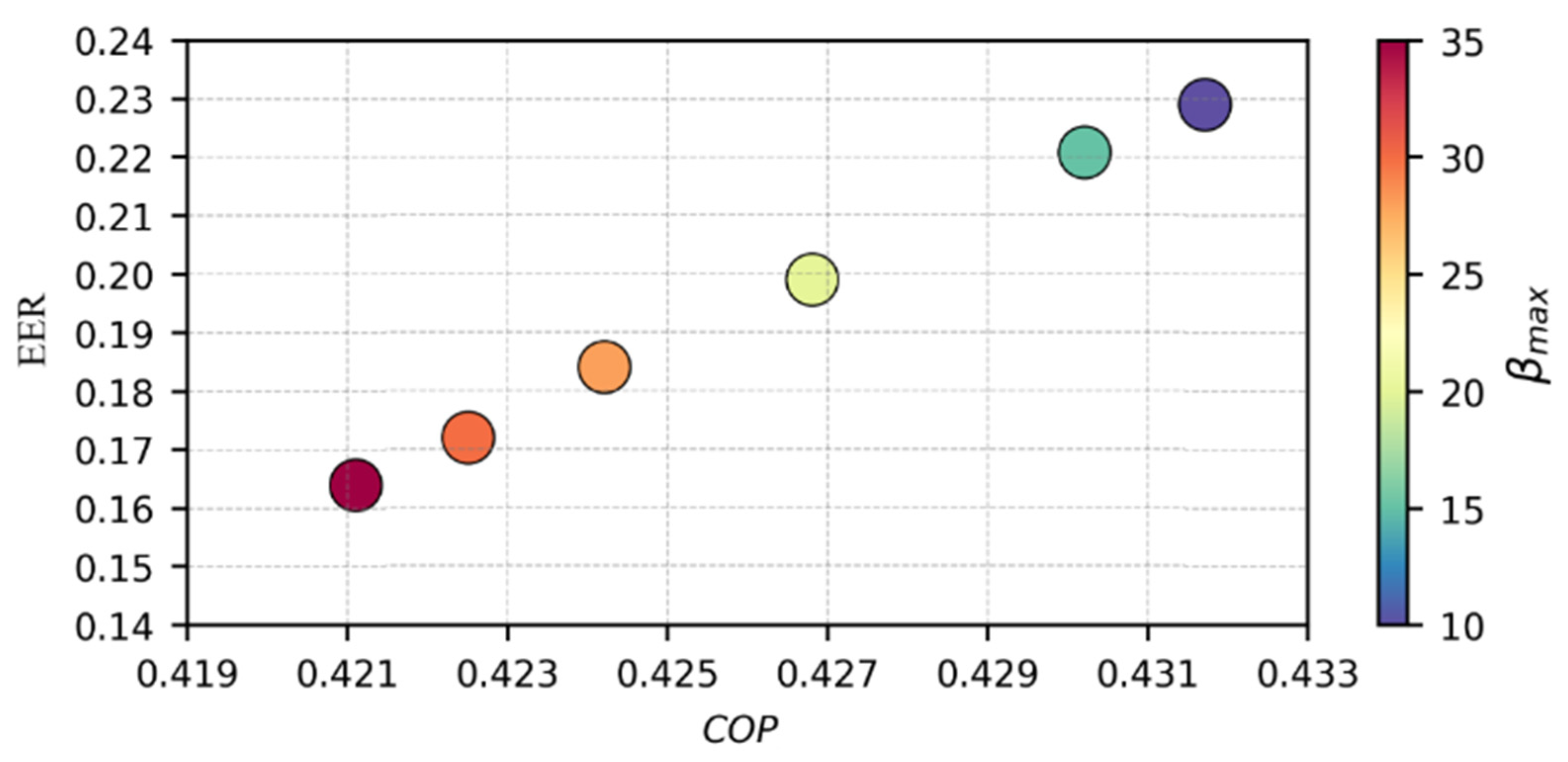
The results were also plotted with reference to TES—specifically, the 3D bubble chart in
Figure 6 shows the relationships between COP, EER, and
.
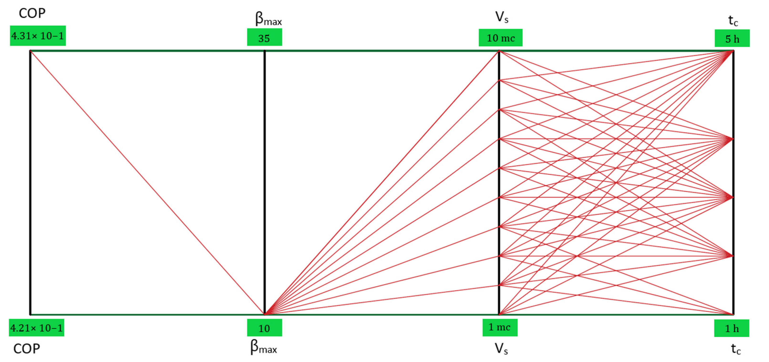
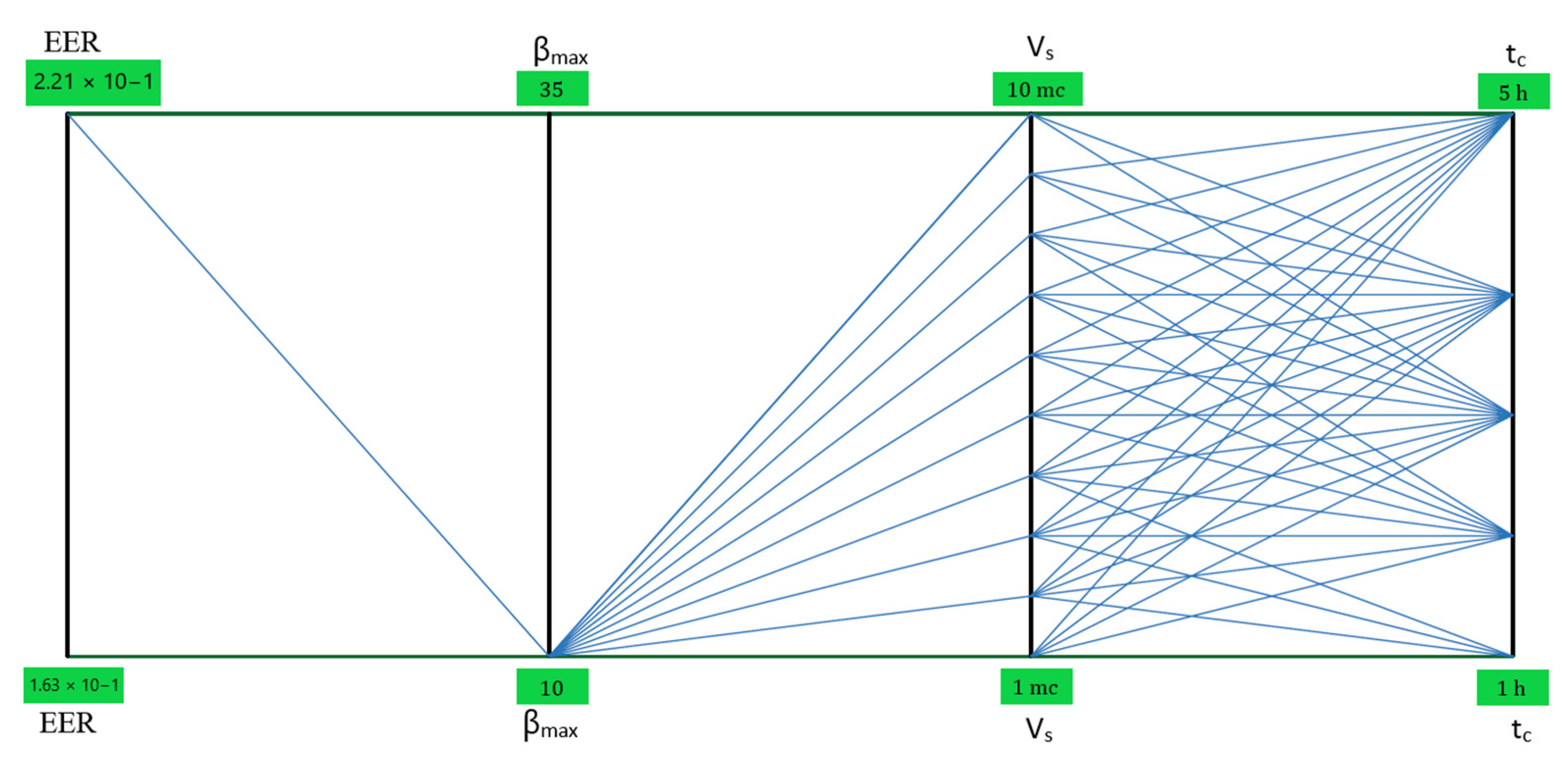
Figure 7 and
Figure 8 show the parallel coordinate charts of the COP and EER output variables, respectively, in the optimized case. This is a particularly useful tool for plotting the input and output variables of each design simultaneously.
5. Discussions
This section presents a discussion of the optimization process. As shown in
Figure 2, the expanded charge times (
) reduce the power absorption to the compressor. Instead, there is a direct relationship between the power absorption to the compressor and the storage volumes
and compression ratios
.
Figure 3 indicates that the CAES discharge time
is directly related to all three input factors. The most influential factor is the volume of the CAES tank
. It is beneficial to have the longest possible discharge times (
) in order to have a functional mechanical storage system for the power supply of the residential building.
Furthermore, increasing the storage volume can be useful within certain limits, as it can be seen that as this factor increases, the power consumption to the compressor also increases significantly. Increasing the charging time to the upper limit of 5 h, on the other hand, has a twofold positive effect: a reduction in power consumption and an increase in the discharge interval (the second most important factor after the storage volume).
It was assumed that the consumption of the building taken as a case study is concentrated in the evening hours, so during the day it accumulates electrical energy in elastic form for 5 h, and in the evening this energy is reconverted into electrical form to supply domestic users.
The maximum compression ratio is almost irrelevant to the discharge time, but it is the second most important factor in terms of incidence with respect to the increase in compressor power. Therefore, within appropriate limits related to the space of the building and the purchase costs of the tanks, it is convenient to work with larger storage rather than higher storage pressures.
In
Figure 4, it is possible to notice the inverse relation between
and
. Therefore, in order to maximize the ratio between electrical energy produced during the discharge phase of the CAES system and electrical energy spent for the charge, it is necessary to reduce the compression ratio to a minimum. The reduction in the maximum pressure under which the CAES operates is a need in line with the considerations made previously for the other output variables. The efficiency of mechanical energy storage is substantially independent of the other input factors; it is not by chance that no trend emerges due to the diameter or color of the bubbles. With fixed
, there is the same efficiency for any combination of the factors
and
, provided that the relative experiments have not been discarded from the design table. For this reason, in the low-yield zone of the graph and, thus, at the high pressures of the CAES, only a few combinations of the two factors are possible (blue bubbles with large diameters, which indicate low storage volumes with extended charge times). The high-yield zone is the one to focus on for further analysis. This zone is also the one that offers the most choice in the configuration of the optimal setup for the system (bubbles of different colors with diameters of various sizes, meaning wider ranges of values in which to try to combine the input factors).
The resulting optimized CAES configuration, consistent with the interval thresholds set in the workflow of the problem, provides the following input factors for the solution:
;
;
.
Figure 6 highlights the fact that COP and EER are inversely proportional to the compression ratio. Therefore, for HTTES and LTTES systems, it is also convenient to work with
= 10.
To maximize COP and EER, a pair of and values is not specifically required, but it is essential that the compression ratio is set to a minimum. Therefore, the configuration adopted to optimize the CAES problem is also suitable for HTTES and LLTES systems. The fact that the trends of mechanical and thermal storage systems are not in contrast with one another is a very positive aspect. The input factor values of the experiment optimized for CAES can be confirmed for HTTES and LLTES systems as well.
The qualitative analysis of the trends allows us to define the optimized configuration for the micro-CAES + TES system under study.
In accordance with the equations reported in [
29], starting from CAES, a single-stage reciprocating compressor (
N = 1) is required to process an airflow rate of
≈ 2.75 L/s (FAD) to a maximum pressure of 10 bar. The compressor requires a 1.5 kW electric motor. A comparison of the results with real models from manufacturers’ catalogues was carried out, and the reliability of the study model was confirmed. The compressor takes 5 h to fill the CAES tank from the initial pressure of 5 bar to the final pressure of 10 bar, consuming about 6 kWh of electricity supplied by the solar photovoltaic system in the process. The compressed air storage tank has a volume of 10 m³, equivalent to an overall length of 5.2 m by 1.65 m in diameter. During the loading phase, a total of almost 60 kg of air is stored to be used later for expansion.
Since the compressor is single-stage (N = 1), the HTTES system recovers the thermal waste from the charging phase exclusively through a heat exchanger located downstream of the compressor. The maximum temperature of the compressed air leaving the stage is estimated at about 190 °C, and the total heat recoverable in one charge is 8.6 MJ.
Moving on to the discharge phase of the CAES, this involves emptying the tank in order to supply the previously selected pneumatic reed valve motor, in order to deliver an electrical power of 3 kW to the user. The motor is supplied at a constant pressure of 5 bar, thanks to a pressure reducer installed downstream of the tank. Once this pressure threshold is reached in storage, the reducer interrupts the flow, and a mass of air equal to that discharged remains trapped in the CAES tank, i.e., about 60 kg. The discharge lasts a total of 0.17 h (≈10 min). The minimum air temperature at the end of the expansion is just below −66 °C, and the cooling capacity that can be recovered through the heat exchanger of the LTTES system is about 4.6 MJ.
The mechanical and thermal storage values used for the optimized configuration return of 8.4%, COP of 0.43, and EER of 0.23.
Preliminary Analysis of Costs
Finally, a preliminary investigation of the system is presented, with the analysis of costs and relative comparison with the most common electrochemical storage systems on a small scale.
Table 4 shows the purchase costs of the main components of the micro-CAES + TES system studied.
To make the comparison with battery storage systems, it was considered that the average household consumption in the evening hours for a household amounts to approximately 4.5 kWh. Thus, for batteries, the cost analysis is summarized in
Table 5.
For lead–acid and lead-gel batteries, it should be noted that about 50% of energy is retained in the charge–discharge cycle to avoid damaging them. For this, a 9 kWh battery is used. For lithium-ion technology, on the other hand, 80% of use is considered to be 5.7 kWh. In terms of purchase cost, the micro-CAES system is also cheaper than batteries.
Given that the CAES system under consideration can generate 0.51 kWh of electrical energy to the user at a constant power of 3 kW, it was determined what configuration the CAES system should have in order to generate a significant amount of energy, taking into account the purchase cost and available space.
To obtain 3 kWh from the discharge, it would be necessary for the discharge to last for 1 h. At this point, there are two options: increase the maximum compression pressure, which compromises the already low efficiency of mechanical energy storage; or increase the storage tank size.
In the first case, a compressor with a maximum air pressure of 35 bar and a 13 kW motor is required, which is incompatible with the nominal power of a typical domestic photovoltaic system. In addition, the mechanical energy storage efficiency would drop to 6.16%.
In the second case, a 60 m3 tank would need to be filled to 10 bar in 5 h using a 9 kW compressor, and the efficiency (a function of ) would remain fixed at 8.4%.
The efficiency of CAES (8.4%) is almost one-tenth of the efficiency of the most efficient batteries present on the market (70–90%).
The only advantages that a micro-CAES + TES system such as the one studied can offer compared to state-of-the-art batteries lie in its longer service life and the possibility of recovering the thermal waste to be used for heating/cooling the building. The years of service life for the system studied, as shown in
Table 6, can be estimated by taking into account the average life of the compressor, which is the component that is potentially the most prone to failures and which, moreover, requires more attention for maintenance.
6. Conclusions
This study investigated the feasibility of compressed-air energy storage (CAES) systems, with the objective of carrying out the optimization of mechanical and thermal storage systems for small-scale trigeneration, designed for a single-family residential building equipped with a photovoltaic system with a rated power of 3 kW.
When dealing with a multi-objective optimization problem, the optimal solution obtained is never unique. The results identify a set of potentially optimal solutions. Among these, it is up to the decision-maker to choose which objective to favor in the optimization strategy. In particular, for this case study, the best configuration for the CAES was obtained under the following conditions:
Reduced compression ratios (). This allows for maximizing the mechanical accumulation efficiency of the CAES and reducing the maximum power absorption to the compressor, which is a very important aspect in the case of storage systems powered by domestic photovoltaic systems, as in this case study. Finally, it is true that the discharge time is reduced, but the effect is marginal when compared to and . This means that can still be lowered, compensating for the effect on the discharge time by pushing slightly more on the other two input factors.
High charging time (). The power absorption is contained at compression, and the discharge time of the CAES is increased.
High storage volumes (). As this is the main factor influencing the increase in the discharge time of the CAES, even if the power consumption increases, the effect is still compensated by the choice to work with low compression ratios.
The results of the optimization showed some critical issues. A very small percentage of the electrical energy stored in elastic form is again convertible into electrical energy. The efficiency of CAES is nearly one-tenth of that of the most efficient batteries on the market, and the discharge times are also extremely short. At the same time, for TES systems, only 43% of the net electrical energy expended is recoverable as heat in the HTTES system, with the hot source (compressed air) at 190 °C; in the LTTES system, the recoverable cooling capacity reaches about 23% in relation to the net electrical energy expended, with the cold source (expanded air) at a temperature of −66 °C. A tank with a volume of 10 m3 is not easy to install in a residential building.
The micro-CAES + TES system studied is inefficient, and is more expensive than batteries. The only advantages that micro-CAES + TES systems offer compared to batteries lie in their longer service life and in the possibility of recovering the thermal waste to be used for heating/cooling the building. The critical aspect of the system, optimized as much as possible in its configuration, can be attributed to the disproportion between the air consumption of the reed motor in the discharge phase and the flow rate that the compressor is able to process during the charging phase. The use of air motors, as widely accessible devices, has proven to be unsustainable for a micro-CAES system, even if optimized.
Therefore, in the future, this micro-CAES + TES system for small-scale trigeneration could be improved as a result of the optimization carried out in this work. If experimentation with new expanders is able to reduce the consumption of compressed air during discharge, the system could be configured as a viable alternative to batteries for the accumulation of photovoltaic energy. This is because the system offers indisputable advantages linked, as seen, to the exploitation of the thermal waste of the process to be used to heat/cool the building. Furthermore, the estimated useful life is double or even triple compared to some types of batteries currently on the market.
An interesting implementation of this study could involve the possibility of coupling the proposed system with an air–ground heat exchanger.
Author Contributions
Conceptualization, P.M.C., C.B., S.P. and D.M.; Data curation, P.M.C., C.B., S.P., D.M. and N.M.; Formal analysis, P.M.C., C.B., S.P., D.M. and N.M.; Investigation, P.M.C., C.B., S.P., D.M. and N.M.; Methodology, P.M.C., C.B., S.P. and D.M.; Resources, P.M.C., C.B., S.P. and D.M.; Software, P.M.C., C.B., S.P. and D.M.; Supervision, P.M.C., C.B., S.P. and D.M.; Validation, P.M.C., C.B., S.P. and D.M.; Visualization, P.M.C., C.B., S.P., D.M. and N.M.; Writing—original draft, P.M.C., C.B., S.P. and D.M.; Writing—review & editing, P.M.C., C.B., S.P. and D.M. All authors have read and agreed to the published version of the manuscript.
Funding
This research received no external funding.
Institutional Review Board Statement
Not applicable.
Informed Consent Statement
Not applicable.
Data Availability Statement
Not applicable.
Acknowledgments
We thank Francesco Tramonte of the Department of Engineering for Innovation at the University of Salento for support in the development of this study.
Conflicts of Interest
The authors declare no conflict of interest. The funders had no role in the design of the study; in the collection, analyses, or interpretation of data; in the writing of the manuscript; or in the decision to publish the results.
References
- Mazzeo, D.; Matera, N.; De Luca, P.; Baglivo, C.; Congedo, P.M.; Oliveti, G. Worldwide geographical mapping and optimization of stand-alone and grid-connected hybrid renewable system techno-economic performance across Köppen-Geiger climates. Appl. Energy 2020, 276, 115507. [Google Scholar] [CrossRef]
- Mazzeo, D.; Matera, N.; De Luca, P.; Baglivo, C.; Congedo, P.M.; Oliveti, G. A literature review and statistical analysis of photovoltaic-wind hybrid renewable system research by considering the most relevant 550 articles: An upgradable matrix literature database. J. Clean. Prod. 2021, 295, 126070. [Google Scholar] [CrossRef]
- Beaudin, M.; Zareipour, H.; Schellenberglabe, A.; Rosehart, W. Energy storage for mitigating the variability of renewable electricity sources: An updated review. Energy Sustain. Dev. 2010, 14, 302–314. [Google Scholar] [CrossRef]
- Gallo, A.B.; Simõões-Moreira, J.R.; Costa, H.K.M.; Santos, M.M.; Moutinho dos Santos, E.M. Energy storage in the energy transition context: A technology review. Renew. Sustain. Energy Rev. 2016, 65, 800–822. [Google Scholar] [CrossRef]
- Rostamizadeh, M.; Khanlarkhani, M.; Sadrameli, S.M. Simulation of energy storage system with phase change material (PCM). Energy Build. 2012, 49, 419–422. [Google Scholar] [CrossRef]
- Cheekatamarla, P.K.; Kassaee, S.; Abu-Heiba, A.; Momen, A.M. Near isothermal compressed air energy storage system in residential and commercial buildings: Techno-economic analysis. Energy 2022, 251, 123963. [Google Scholar] [CrossRef]
- Mazzeo, D.; Oliveti, G. Thermal field and heat storage in a cyclic phase change process caused by several moving melting and solidification interfaces in the layer. Int. J. Therm. Sci. 2018, 129, 462–488. [Google Scholar] [CrossRef]
- Nekoonam, S.; Ghasempour, R. Modeling and optimization of a thermal energy storage unit with cascaded PCM capsules in connection to a solar collector. Sustain. Energy Technol. Assess. 2022, 52, 102197. [Google Scholar] [CrossRef]
- Pal, P.; Mukherjee, V. Off-grid solar photovoltaic/hydrogen fuel cell system for renewable energy generation: An investigation based on techno-economic feasibility assessment for the application of end-user load demand in North-East India. Renew. Sustain. Energy Rev. 2021, 149, 111421. [Google Scholar] [CrossRef]
- Singh, A.; Baredar, P.; Gupta, B. Techno-economic feasibility analysis of hydrogen fuel cell and solar photovoltaic hybrid renewable energy system for academic research building. Energy Convers. Manag. 2017, 145, 398–414. [Google Scholar] [CrossRef]
- Mazzeo, D.; Baglivo, C.; Matera, N.; Congedo, P.M.; Oliveti, G. A novel energy-economic-environmental multi-criteria decision-making in the optimization of a hybrid renewable system. Sustain. Cities Soc. 2020, 52, 101780. [Google Scholar] [CrossRef]
- Baglivo, C.; Mazzeo, D.; Oliveti, G.; Congedo, P.M. Technical data of a grid-connected photovoltaic/wind hybrid system with and without storage battery for residential buildings located in a warm area. Data Brief 2018, 20, 587–590. [Google Scholar] [CrossRef] [PubMed]
- Mazzeo, D.; Oliveti, G.; Baglivo, C.; Congedo, P.M. Energy reliability-constrained method for the multi-objective optimization of a photovoltaic-wind hybrid system with battery storage. Energy 2018, 156, 688–708. [Google Scholar] [CrossRef]
- Angrisani, G.; Akisawa, A.; Marrasso, E.; Roselli, C.; Sasso, M. Performance assessment of cogeneration and trigeneration systems for small scale applications. Energy Convers. Manag. 2016, 125, 194–208. [Google Scholar] [CrossRef]
- Rouindej, K.; Samadani, E.; Fraser, R.A. A comprehensive data-driven study of electrical power grid and its implications for the design, performance, and operational requirements of adiabatic compressed air energy storage systems. Appl. Energy 2020, 257, 113990. [Google Scholar] [CrossRef]
- Mozayeni, H.; Wang, X.; Negnevitsky, M. Dynamic analysis of a low-temperature Adiabatic Compressed Air Energy Storage system. J. Clean. Prod. 2020, 276, 124323. [Google Scholar] [CrossRef]
- Tong, Z.; Cheng, Z.; Tong, S. A review on the development of compressed air energy storage in China: Technical and economic challenges to commercialization. Renew. Sustain. Energy Rev. 2021, 135, 110178. [Google Scholar] [CrossRef]
- Chen, L.; Zheng, T.; Mei, S.; Xue, X.; Liu, B.; Lu, Q. Review and prospect of compressed air energy storage system. J. Mod. Power Syst. Clean Energy 2016, 4, 529–541. [Google Scholar] [CrossRef]
- Huang, B.; Qiu, X.; Wang, W.; Li, H.; Zhou, W. Overview of research situation and progress on compressed air energy storage technology. IOP Conf. Ser. Earth Environ. Sci. 2019, 295, 012020. [Google Scholar] [CrossRef]
- Wang, J.; Ma, L.; Lu, K.; Miao, S.; Wang, D.; Wang, J. Current research and development trend of compressed air energy storage. Syst. Sci. Control Eng. 2017, 5, 434–448. [Google Scholar] [CrossRef] [Green Version]
- Akinyele, D.O.; Rayudu, R.K. Review of energy storage technologies for sustainable power networks. Sustain. Energy Technol. Assess. 2014, 8, 74–91. [Google Scholar] [CrossRef]
- Li, Y.; Wang, X.; Li, D.; Ding, Y. A trigeneration system based on compressed air and thermal energy storage. Appl. Energy 2012, 99, 316–323. [Google Scholar] [CrossRef]
- Sala, J. Thermal energy storage (TES) systems for cogeneration and trigeneration systems. In Advances in Thermal Energy Storage Systems; Cabeza, L.F., Ed.; Woodhead Publishing Series in Energy; Woodhead Publishing: Sawston, UK, 2015; pp. 493–509. [Google Scholar] [CrossRef]
- Kondoh, J.; Ishii, I.; Yamaguchi, H.; Murata, A.; Otani, K.; Sakuta, K.; Higuchi, N.; Sekine, S.; Kamimoto, M. Electrical energy storage systems for energy networks. Energy Convers. Manag. 2000, 41, 1863–1874. [Google Scholar] [CrossRef]
- Manchester, S.; Swan, L. Compressed Air Storage and Wind Energy for Time-of-day Electricity Markets. Procedia Comput. Sci. 2013, 19, 720–727. [Google Scholar] [CrossRef]
- Sciacovelli, A.; Li, Y.; Chen, H.; Wu, Y.; Wang, J.; Garvey, S.; Ding, Y. Dynamic simulation of Adiabatic Compressed Air Energy Storage (A-CAES) plant with integrated thermal storage—Link between components performance and plant performance. Appl. Energy 2017, 185, 16–28. [Google Scholar] [CrossRef]
- Yu, H.; Engelkemier, S.; Gençer, E. Process improvements and multi-objective optimization of compressed air energy storage (CAES) system. J. Clean. Prod. 2022, 335, 130081. [Google Scholar] [CrossRef]
- Luo, X.; Wang, J.; Krupke, C.; Wang, Y.; Sheng, Y.; Li, J.; Xu, Y.; Wang, D.; Miao, S.; Chen, H. Modelling study, efficiency analysis and optimisation of large-scale Adiabatic Compressed Air Energy Storage systems with low-temperature thermal storage. Appl. Energy 2016, 162, 589–600. [Google Scholar] [CrossRef]
- Congedo, P.M.; Baglivo, C.; Carrieri, L. Hypothesis of thermal and mechanical energy storage with unconventional methods. Energy Convers. Manag. 2020, 218, 113014. [Google Scholar] [CrossRef]
- Congedo, P.M.; Baglivo, C.; Carrieri, L. Application of an unconventional thermal and mechanical energy storage coupled with the air conditioning and domestic hot water systems of a residential building. Energy Build. 2020, 224, 110234. [Google Scholar] [CrossRef]
- Sciacca, E. Algoritmi Evolutivi Multiobiettivo e Possibilistic Worst-Case Distance per l’ottimizzazione di circuiti elettronici, Università degli Studi di Catania. pp. 20–28. Available online: http://webusers.oact.inaf.it/esciacca/publications/Tesi_Sciacca.pdf (accessed on 10 May 2022).
- Hanne, T. Global Multiobjective Optimization Using Evolutionary Algorithms. J. Heuristics 2000, 6, 347–360. [Google Scholar] [CrossRef]
Figure 1.
Workflow of the optimization problem on modeFRONTIER.
Figure 1.
Workflow of the optimization problem on modeFRONTIER.
Figure 2.
Relationship between the maximum power absorbed by the compressor and the input variables .
Figure 2.
Relationship between the maximum power absorbed by the compressor and the input variables .
Figure 3.
Relationship between the discharge time and the input variables .
Figure 3.
Relationship between the discharge time and the input variables .
Figure 4.
The x and y axes of the 4D bubble chart represent and , respectively, while the diameter indicates the and the color indicates the .
Figure 4.
The x and y axes of the 4D bubble chart represent and , respectively, while the diameter indicates the and the color indicates the .
Figure 5.
Correlation matrix to summarize the results referring to CAES. Values close to +1 indicate that the two variables are positively correlated, while values close to −1 indicate a negative correlation. If the value is close to 0, the variables are not correlated.
Figure 5.
Correlation matrix to summarize the results referring to CAES. Values close to +1 indicate that the two variables are positively correlated, while values close to −1 indicate a negative correlation. If the value is close to 0, the variables are not correlated.
Figure 6.
The x and y axes of the 3D bubble chart represent and , respectively, while color indicates the values of .
Figure 6.
The x and y axes of the 3D bubble chart represent and , respectively, while color indicates the values of .
Figure 7.
Parallel coordinate chart of the COP output variable in the optimized case.
Figure 7.
Parallel coordinate chart of the COP output variable in the optimized case.
Figure 8.
Parallel coordinate chart of the EER output variable in the optimized case.
Figure 8.
Parallel coordinate chart of the EER output variable in the optimized case.
Table 1.
Thermodynamic coefficients and parameters that are not subject to optimization.
Table 1.
Thermodynamic coefficients and parameters that are not subject to optimization.
| Parameters | Description | Values |
|---|
| Specific heat at constant dry air pressure | |
| Ratio of specific heats in dry air | |
| Characteristic exponent of polytropic process in the compression cycle | |
| Atmospheric pressure | |
| Minimum operating pressure | |
| Electric power generated by the alternator | |
| Power delivered by the pressure-fed reed motor | |
| Specific constant for dry air | |
| Atmospheric temperature | |
| Temperature of the air leaving the LTTES heat exchanger | |
| Temperature of the air stored in the CAES tank | |
| Air consumption of the reed motor (FAD) | |
| Minimum alternator efficiency | |
| Efficiency of the electric motor of the compressor | |
| Global compression efficiency | |
| Isoentropic expansion efficiency | |
Table 2.
Input variables.
Table 2.
Input variables.
| Input Variable | Description | Lower/Upper Limit | Step | Number of Inputs Generated |
|---|
| Relative charging time | | | |
| Maximum compression ratio | | | |
| Volume of the CAES tank | | | |
Table 3.
Output variables and optimization choices in the workflow.
Table 3.
Output variables and optimization choices in the workflow.
| Output Variable | Objective Type |
|---|
| <3 kW |
| Maximize |
| Maximize |
| Maximize |
| Maximize |
Table 4.
The purchase costs of the main components of the micro-CAES + TES system.
Table 4.
The purchase costs of the main components of the micro-CAES + TES system.
| Component | Cost |
|---|
| Tank (10 m3–10 bar) | EUR 8000 |
| Compressor (10 bar–1.5 kW) | EUR 500 |
| Air heat exchangers | EUR 250 × 2 = EUR 500 |
| Pneumatic reed motor | EUR 1800 |
| Alternator (3 kW) | EUR 300 |
| Total | EUR 11,100 |
Table 5.
The purchase costs of storage batteries.
Table 5.
The purchase costs of storage batteries.
| Battery | Cost |
|---|
| Lithium battery (5.7 kWh) | EUR 5000 |
| Lead–acid battery (9 kWh) | EUR 2500 |
| Lead-gel battery (9 kWh) | EUR 3000 |
Table 6.
Comparison of estimated service life years for different storage systems.
Table 6.
Comparison of estimated service life years for different storage systems.
| Accumulation System | Estimated Service Life |
|---|
| Micro-CAES | 20 years |
| Lithium-ion battery | 10 years |
| Lead–acid battery | 3 years |
| Lead-gel battery | 5 years |
| Publisher’s Note: MDPI stays neutral with regard to jurisdictional claims in published maps and institutional affiliations. |
© 2022 by the authors. Licensee MDPI, Basel, Switzerland. This article is an open access article distributed under the terms and conditions of the Creative Commons Attribution (CC BY) license (https://creativecommons.org/licenses/by/4.0/).


 ,
, 


