Article

Research on Rock Damage Evolution Based on Fractal Theory-Improved Dynamic Tensile-Compression Damage Model

1
School of Architectural Engineering, Guizhou University for Nationalities, Guiyang 550025, China
2
School of Mining, Guizhou University, Guiyang 550025, China
3
School of Safety Engineering, China University of Mining and Technology, Xuzhou 221116, China
*
Author to whom correspondence should be addressed.
Energies 2022, 15(17), 6194; https://doi.org/10.3390/en15176194
Submission received: 20 July 2022 / Revised: 4 August 2022 / Accepted: 23 August 2022 / Published: 25 August 2022
(This article belongs to the Special Issue New Advances in Rock Mechanics and Underground Thermal Energy Storage)

Abstract

:
According to the characteristics that the dynamic tension of rock material is elastic brittle and the dynamic compression is elastic plastic, based on previous studies, the influence of initial damage is considered in the established compression damage model, and the calculation formula of the damage threshold used to evaluate whether the surrounding rock is affected by blasting is given. According to the classic rock impact dynamic damage model and statistical damage mechanics theory, a rock compressive and tensile statistical damage constitutive model and impact damage model under blasting load is proposed. Based on the proposed damage model and the classic dynamic tensile damage model, the numerical simulation of blasting damage was carried out, and the numerical calculation results were compared with the field measurement results. Based on the established damage model, to further clarify the damage evolution characteristics of rock under blasting load, fractal dimension theory was introduced to analyze the rock damage under blasting loads with different blasting hole network parameters. The results show that compared with the axial direction of the blast hole, the direction of blast hole diameter is the main direction of blasting fracture extension. Tensile fracture mainly occurs along the hole diameter direction, and compression fracture mainly occurs below the hole bottom. Compared with the numerical calculation results based on the classical dynamic tensile damage model, the blasting fracture range obtained according to the damage model, especially the fracture depth below the bottom of the hole, was not much different from the measured value and was closest to the measured value. The crack density of 1 us, 90 aperture, and 130 aperture was larger than that of the other working conditions. Among them, the crack density of 130 aperture was the largest, followed by 90 aperture. At 2~3 us after initiation, cracks between two blast holes, radial cracks and circumferential cracks around two blast holes, and obvious cracks were formed around blastholes; at 4~5 us after initiation, the shock wave front decreased rapidly and propagated outward in the form of the compression wave. The crack propagation velocity was much smaller than that at 1~3 us after initiation. In summary, the proposed damage model is reasonable and has certain engineering practicability.

1. Introduction

Under the action of the blasting load, the dynamic constitutive relationship of rock is a research hotspot in the fields of blast engineering and underground protection engineering. A large number of test results show that the rock has the characteristics of different compressive and tensile strengths [1,2]. The damage and fracture of rock under blasting load is a complex dynamic evolution process. To explore this process, scholars have established relevant blasting damage models based on different theories. The impact damage model proposed by Grady et al. [3], widely used in blast engineering, belongs to the classical impact damage model. It is proposed for tensile damage, without considering the compression damage of rock. They believe that the rock only incurs elastic deformation and failure under compression. Assuming that the internal cracks uniformly distributed in the rock are activated under tensile stress, and the number of activated cracks obeys the Weber distribution of two parameters, the damage variable is defined by the number of cracks activated per unit volume, and then the reduction of rock stiffness is described. The GK model of isotropic tensile damage of rock is proposed. On the basis of the GK model, Taylor et al. [4], combined with the expression of rock elastic parameters obtained by the self-consistent method of Budiansky et al. [5] and the Grady et al. [3,4,5] calculation formula of rock dynamic fracture block, established the relationship between damage variable and crack density, effective Poisson’s ratio and effective bulk modulus, and coupled it to the general linear elastic constitutive of rock, obtaining the TCK model. Kuszmaul [6] retained the research results of crack activation rate and average crack size from the GK model, considered the material overlap of the stress release zone around high-density microcracks and considered the damage reduction in the crack activation rate. The expression of crack density was modified, and the KUS model was proposed. Based on the research and theory of Kuszmaul [6], Hu et al. [7] introduced the compression damage variable and its evolution law, considering the volume compression damage of rock, established the dynamic damage model of volume compression and tension, and verified the rationality of the proposed model by blasting numerical simulation. Thorne et al. [8], through different definitions of damage variables, proposed the Thorne model on the basis of the above model. Yang et al. [9] defined the total tensile strain at the rock element point as the sum of three logarithmic principal tensile strains, simulated the growth of crack density in the form of the empirical Paris law, and proposed the Yang model including damage accumulation and load rate dependence. Xuelong Hu et al. [10], based on the unified strength theory, established the elastoplastic damage constitutive model of rock. The uniaxial compression test, Brazilian disc splitting test and single-hole blasting test of rock were numerically simulated by Fortran language. At the same time, the numerical simulation results were compared with the experimental data, the numerical results of the classical model and the theoretical calculation results by Zhichao Sun et al. [11]. In order to study the fracture damage of rock mass and the vibration law of bench blasting under blasting conditions, the continuous damage constitutive model for materials was used to numerically simulate the bench blasting process of rock and soil, and the vibration velocity of characteristic points was obtained. The experimental results were in good agreement with the numerical simulation results. In Mengfei Xu et al. [12], the Hoek–Brown elastic-plastic damage model considering the cyclic blasting effect was established and the numerical solution was given in view of the deficiency of numerical calculation methods for the damage zone of the surrounding rock of tunnel excavations by the drilling and blasting method. Most of the existing blasting damage models regard the rock before blasting as a non-destructive state, ignoring the influence of initial damage in rock, and the initial damage largely controls the rock crushing process. Most models only consider the damage response of rock under volume tensile condition; and an idealized elastoplastic constitutive model without considering damage is often used in volume compression, which is quite different from engineering practice.
To describe the damage evolution process of rock under blasting load more comprehensively, this paper starts with the shortcomings of the existing models, according to the different response characteristics of rock under dynamic tensile and compressive stress; and considering the initial damage of rock, the equivalent tensile damage model proposed by Yang et al. [9] is improved, the dynamic damage model of rock under compressive and tensile impact considering initial damage conditions is proposed. The proposed damage model is applied to the numerical simulation of blasting damage. The calculated blasting rupture range is compared with the numerical calculation results of blasting damage based on the classical impact damage model and the field measurement results. The blasting damage characteristics of rock under different blasting hole network parameters are further analyzed to verify the rationality of the proposed model.

2. Establishment of Tension-Compression Damage Model

2.1. Improved Damage Model

Yang et al. [9] believe that only element tensile deformation will incur damage. Tension deformation does not necessarily lead to volume tension, but volume tension must be accompanied by tension deformation. Therefore, compared with the volumetric tensile damage model proposed by Liu (1997) [13], the equivalent tensile damage model proposed by Yang relaxes the condition of rock damage, and it is believed that both volumetric tensile and compression can produce damage. Considering that the mechanical properties of rock have a strain rate effect, they assume that the relationship between the activated crack density C and the volumetric strain θ is [13,14]:
C = a θ θ f b t
θ = i = 1 3 ε i + ε i / 2
In the formula: θ is volumetric strain; θ f is critical tensile volumetric strain; ε i is the main strain in the ith direction, and its value is 1, 2, 3. In this paper, the tension is positive, and the pressure is negative; a and b are rock material constants, and t is time. θ > 0 represents volume stretching; θ < 0 represents volume compression.
Rewrite form Equation (1) to differential form:
d C = a b θ θ f b 1 t d θ + a θ θ f b d t
Combined with the idea of mathematical integration, the incremental integration of Equation (3) is carried out, and the incremental expression of crack density is obtained as follows:
Δ C = a b θ θ f b 1 t θ ˙ d t + a θ θ f b d t
Among them. θ ˙ = d θ d t , θ ˙ is volumetric strain rate.
The set formula Equation (4) shows that the crack density increment is not only related to the strain in a certain time, but also to the volumetric strain rate θ ˙ at a given strain level, and the crack increment increases with the increase in θ ˙ .
In order to make the established model closer to the real situation of rock, the initial damage of rock must be considered in the process of establishing the model. When initial damage exists, the crack density can be expressed as [15]:
C i = Δ C + C 0 = a b θ θ f b 1 t θ ˙ d t + a θ θ f b d t + C 0
In the formula: C0 is the initial crack density per unit volume of rock; C i is the total crack density per unit volume of rock considering the initial damage of the rock. Assuming that the rock is isotropic damage material, the damage degree of rock is expressed by failure probability, and the damage value of meso-element is calculated as:
D = 1 e k V 0 C i l
In the formula: D is the damage variable of rock unit. For the element V0 = 1, according to the damage accumulation criterion proposed by Yang, k and l are 1 and 2, respectively. Combining Equation (5), type 6 can be rewritten as:
D = 1 e c i 2 = 1 e [ { a b θ θ f b 1 t θ ˙ d t + a θ θ f b d t + C 0 } 2 ]
Combining Equations (1)–(7), it can be seen that the crack density in the rock element is closely related to the strain rate, which makes the damage evolution of the rock element have the strain rate effect, and this relationship is consistent with the results obtained from a large number of rock dynamic tests. When the equivalent tensile strain exceeds the threshold value, the crack density increases significantly, resulting in a damage accumulation effect. The results of the rock uniaxial loading test show that, compared with uniaxial tension, the friction force and partial compressive stress are still borne between the crack surfaces of the rock element under uniaxial compression, but the stress is no longer borne between the crack surfaces under uniaxial tension. Under the action of relative volumetric tensile stress, there is an obvious friction effect on the rock under the action of volumetric compressive stress, and the rock around the crack still has certain resistance. Therefore, when the deformation rate is constant, with the increase in equivalent tensile deformation, the volume compression damage growth rate is obviously less than the volume tensile damage growth rate.. When Equation (7) is established, the two are equal, which deviates from the actual situation of the rock. Therefore, Equation (7) needs to be modified so that the damage evolution model can consider the characteristics of tension and compression damage. Based on the improved method proposed by predecessors [16,17,18], this paper also assumes that the damage evolution relationship is divided into volume compression damage and volume tensile damage, and the damage evolution Equation (7) is modified as:
D = 1 e a c b c θ θ f b c 1 t θ ˙ d t + a c θ θ f b c d t + C 0 2 , ε v 0 1 e a t b t θ θ f b t 1 t θ ˙ d t + a t θ θ f b t d t + C 0 2 , ε v < 0
In the formula: ε v is the volumetric strain of rock. The tensile strain is positive and the compressive strain is negative. According to the strain equivalent hypothesis, assuming that the rock is an isotropic material and is in the elastic stage, the relationship between the stiffness degradation of the rock element caused by damage is
E f = ( 1 D ) 2 E
μ f = μ
G f = ( 1 D ) 2 G
In the formula: E f , μ f , G f are the bulk modulus, Poisson’s ratio and elastic modulus of non-damaged rock. E , μ , G are the volume modulus, Poisson’s ratio and elastic modulus of damaged rock.
It can be seen from Equations (9)–(11) that under the assumption of equivalent strain, the effective elastic modulus and effective shear modulus of damaged rock are twice as large as those of non-damaged rock (1 − D)2, the Poisson’s ratio of damaged rock basically does not change. According to previous conclusions, the change of Poisson’s ratio depends on the shape of the crack. If there is a flat and open crack in the material, the Poisson’s ratio will be less than the inherent Poisson’s ratio. Combined with the conclusion of Yang, the relationship between Poisson’s ratio and elastic parameters of damaged rock is unchanged. From Equations (9)–(11), the initial elastic modulus E0 and initial shear modulus G0 of rock element can be calculated as:
E 0 = 1 D 0 2 E
G 0 = 1 D 0 2 G
From Equations (9), (12) and (13), it can be seen that the elastic modulus and shear modulus degradation formula considering the initial elastic modulus and initial shear modulus are expressed as:
E i = 1 D t 2 E 0 / 1 D 0 2
G i = 1 D t 2 G 0 / 1 D 0 2
In the formula: E i and G i are the effective elastic modulus and effective shear modulus of rock after tensile damage, respectively.
Assuming that rock damage does not affect its Poisson’s ratio [16,17], the following formula holds:
E f = 2 G f ( 1 + μ f ) = 3 K f ( 1 + μ f )
E i = 2 G i 1 + μ = 3 K i 1 + μ
In the formula: E f is the bulk modulus of lossless rock.
The relationship of macroscopic elastic constant of rock is:
E f = E 3 ( 1 2 μ f )
The relationship between effective elastic modulus and effective shear modulus of rock can be obtained by combining Equations (16)–(18):
G f = E f 2 ( 1 2 μ f )
The formula (19) shows that the effective shear modulus is 1 2 ( 1 2 μ f ) times the effective elastic modulus, When μ f increases, the effective shear modulus decreases and μ f changes in the range of (0, 0.5).
Assuming that the relationship between the elastic parameters of damaged rock remains unchanged, the expression of tensile damage degradation of rock bulk modulus represented by initial bulk modulus K0 can be obtained from Equations (16) and (18):
K i = 1 D t 2 K 0 / 1 D 0 2
In the formula: K i is the effective elastic modulus of rock after tensile damage.
Assuming that the total deformation of the element consists of plastic deformation and elastic deformation, the total strain increment is calculated as
d ε m = d ε m p + d ε m e
d e i j = d e i j p + d e i j e
In the formula: ε m p is plastic volume deformation; ε m e is elastic volume deformation; e i j p is plastic deviatoric strain; e i j e is elastic deviatoric strain.
Where the elastic strain increment satisfies the Hooke’s law including initial damage and compressive damage, the following holds:
d ε i j e = 1 D 0 2 2 1 D t 2 G 0 d σ i j 3 1 D 0 2 μ 1 D t 2 E 0 d σ k k δ i j
In the formula: d σ i j is stress increment; d σ k k = d σ 11 + d σ 22 + d σ 33 ; D c = 1 e γ ε ¯ p ε ¯ 0 p , ε ¯ 0 p is the equivalent plastic strain threshold.
Calculation formula of plastic strain increment:
d ε i j p = d λ g σ i j = d λ f σ i j
In the formula: d λ is a non-negative plastic factor whose value is determined by the consistency condition. According to Equations (22) and (23), the total strain increment is:
d ε i j = 1 D 0 2 2 1 D t 2 G 0 d σ i j 3 1 D 0 2 μ 1 D t 2 E 0 d σ k k δ i j + d λ f σ i j
The stress is decomposed into spherical stress and deviatoric stress. The constitutive relation of rock elastic damage can be expressed as:
σ m = σ 1 + σ 2 + σ 3 / 3 = K f ε v e = K i ( 1 D ) ε v e
s i j = 2 G f e i j e = 2 G i ( 1 D ) e i j e
In the formula: σ m is the spherical stress component; s i j is the component of deviatoric stress tensor. Considering that the spherical tensor of plastic strain is 0 and the combination Equations (24)–(26), the incremental constitutive equation of ideal elastic-plastic material can be written as:
d e i j = d e i j e + d e i j p = 1 D 0 2 2 1 D t 2 G 0 d S i j + d λ f σ i j d θ = 1 D 0 2 3 1 D t 2 K 0 d P
In the formula: θ < θ f ; d e i j is the increment of deviatoric strain.
The damage evolution Equation (8) and constitutive relations Equations (22)–(27) jointly constitute the dynamic damage model of rock under tension and compression considering the initial damage condition.

2.2. Determination of Parameters and Damage Threshold

According to the experimental experience and related literature, the expression of θ f under uniaxial static loading is:
θ f = 2 μ ε c e = 2 μ σ c e E
In the formula: σ c e is the linear elastic limit stress under uniaxial compression.
During the test, since the uniaxial loading test is easy to implement, in most cases, the parameters in Equation (28) are approximately determined by the uniaxial compression test, and then θ f is calculated.
When the rock is in a non-destructive state, D = 0; when the rock is completely destroyed, D = 1. When the rock damage variable is between 0 and 1, the rock begins to produce macroscopic cracks, and the unit stress increases rapidly and reaches peak strength. At this time, the rock unit produces serious damage. Under the indoor constant strain rate loading condition, Equation (8) can be rewritten as:
D f = D c f = 1 exp [ a c b c ] 2 θ θ f 2 b c + a c 2 θ θ f 2 ( b c + 1 ) θ ˙ con b c + 1 2 , ε v 0 D t f = 1 exp [ a t b t ] 2 θ θ f 2 b t + a t 2 θ θ f 2 ( b t + 1 ) θ ˙ con b t + 1 2 , ε v < 0
In the formula: D f is the critical damage variable corresponding to macroscopic cracks produced by rock elements; D c f and D t f are the critical damage variables under volume tension and volume compression, respectively, corresponding to the state of macroscopic cracks at the moment when the rock begins to appear. θ ˙ con is the equivalent constant strain rate.
Under uniaxial constant strain rate loading, θ ˙ con and θ f are determined by the following expressions:
θ ˙ c o n   = 2 μ ε ˙ c = ε ˙ t
θ f = 2 μ ε cf = ε tf
In the formula: ε ˙ c and ε ˙ t are the constant strain rates of uniaxial compression and tensile tests, respectively; ε cf and ε tf are the critical strain rates of uniaxial compression and tensile, respectively, corresponding to the critical failure state.
The combined Equations (9)–(26) show that the uniaxial compressive and tensile dynamic strength satisfies the following formula:
σ c = E ε c 1 D t f = E ε c exp [ a c b c ] 2 θ θ f 2 b c + a c 2 θ θ f 2 ( b c + 1 ) θ ˙ con b c + 1 2
σ t = E ε t 1 D c f = E ε t exp [ a t b t ] 2 θ θ f 2 b t + a t 2 θ θ f 2 ( b t + 1 ) θ ˙ con b t + 1 2
In the formula: ε c and ε t are the strains corresponding to the peak stress in uniaxial dynamic compression and tensile tests, respectively. According to the theory of rock mechanics, the compressive strength of rock under uniaxial loading is much larger than its tensile strength, so the following formula is established:
σ t < σ c
Under uniaxial dynamic compressive and tensile conditions, the following expressions hold:
d σ 3 d ε 3 ε c = ε 3 = 0
d σ 1 d ε 1 ε t = ε 1 = 0
Combined Equations (32)–(36) with indoor high strain rate test, parameters ac, bc, at, bt are obtained by fitting.
According to the existing research results, for some complex rock blasting impact problems, the damage zone around the blast hole is the result of tensile–compressive stress. Among them, 0.1 < D c f < 0.2; 0.2 < D t f < 0.5. During rock blasting, rock incurs serious degradation phenomenon, with longitudinal wave velocity showing a downward trend. According to the relevant provisions of blast engineering of rock foundation excavation engineering construction technical specification’ of hydraulic structure PL/T 5389-2007, when the reduction rate of sound velocity after the blasting of rock mass in the same part compared with that in the non-destructive rock mass before blasting η is greater than 15%, it is considered that blasting produces a rupture phenomenon on the rock.
The relationship between the longitudinal wave velocity of the rock element and the damage variable can be expressed by the following equation:
D = 1 c / c 2
In the formula: c and c are the longitudinal wave velocity of damaged rock and the longitudinal wave velocity of non-destructive rock, respectively.
Combining (37), for broken rock, the damage variable satisfies the following:
D D f = 0.28

3. Model Verification

3.1. Model Validation Scheme

Double-hole blasting is relatively simple and representative. Therefore, the numerical simulation of double-hole blasting damage is usually used to determine the blasting rupture range, and the numerical calculation results are compared with the field measurement results to verify the rationality of the damage model. In order to further verify and characterize the rationality and applicability of the proposed model, the numerical results of the proposed damage model were compared with those of Liu model and Yang model.

3.2. Field Test Scheme of Blasting Operation

The change of longitudinal wave velocity in rock before and after blasting was measured by borehole acoustic wave velocity test, and the blasting fracture damage area was determined according to Equations (37) and (38). The rock in the test area is limestone, and the rock density is 2630 kg/m3. Explosive was emulsion explosive, density 1220 kg/m3, drug coil diameter 0.032 m, hole diameter 0.09 m, hole depth 2.8 m; the diameter of acoustic hole was 0.056 m, the depth of hole was 4.0 m, and the hole spacing was 0.4 m. The acoustic wave velocity measurement instrument was a non-metallic ultrasonic instrument and sensor. Field blasting test and acoustic wave arrangement are shown in Figure 1. The test area is shown in Figure 2. The model profile is shown in Figure 3.

3.3. Numerical Validation

The ANSYS-LSDYNA finite element program was used to establish the three-dimensional model. The principle of grid division was as follows: taking the center line of the borehole as the axis, the grid division of rock units around the borehole was dense, and the grid division of the area far from the borehole was sparse, with 82,548 grids. The blasting load was applied on the charge section in Figure 2. The detonation product equation is the JWL state equation in ANSYS, and the state equation as shown in Equation (39).
p eos = A 1 ω R 1 V e R 1 V + B 1 ω R 2 V e R 2 V + ω E e V
In the formula: P is detonation pressure, A, B, R1, R2 and ω are material constants; V is the relative volume, Ee is the internal energy of explosive unit.
The constitutive relation proposed in this paper and the constitutive relation proposed in the References were imported into ANSYS numerical model for blasting damage loading, respectively. When unloading, the damage variable D remains unchanged, and each unloading modulus is determined by Equations (12)–(17).
For the compressive and tensile damage constitutive model proposed in this paper: E f = 46.6 GPa, μ f = 0.3, θ f = 1.8 × 10⁻⁴, ac = 8.12 × 10⁸, bc = 1.74, bt = 1.71, Df = 0.28. Volumetric tensile damage constitutive model proposed in the literature [13]: E f = 46.6 GPa, μ f = 0.3, ε v c = 1.8 × 10⁻⁴, k = 1, l = 1, A = 7 × 10¹⁰, B = 2, Df = 0.28. Volumetric tensile damage constitutive model proposed in the literature [9]: E f = 46.6 GPa, μ f = 0.3, θ f = 1.8 × 10⁻⁴, k = 1, l = 2, m = 3.15 × 10⁶, n = 1, Df = 0.28.
The numerical simulation results are shown in Figure 3. The blasting range mainly expanded along the apertures of the two shots, and the radial fracture expansion range was larger than the axial fracture expansion range, which is similar to the conclusion in References [19,20]. The fracture extension depth was the largest in the axial direction of the hole and just below the bottom of the hole. The reason is that after the explosion of the explosive at the initiation point (bottom of the hole), the compression shock wave is generated in the hole wall and bottom area, and the circumferential direction of the hole is mainly damaged by tensile stress, resulting in the extension of tensile damage along the hole diameter [21]. The main compressive stress is below the bottom of the hole, which leads to the extension of this part of the fracture along the axial direction of the hole. Since the compressive strength of rock is much larger than the tensile strength, the shot aperture is the main direction of fracture extension. The maximum fracture radius appears near the free surface of the hole, which is mainly caused by the reflection tensile wave of the explosion stress wave. The radial fracture propagation distance near the free surface of the blasthole orifice is the largest. Combined with Figure 3 and the above analysis, the improved damage model proposed in this paper considers the different characteristics of rock compressive and tensile damage.
The comparison between the numerical calculation results and the measured results is shown in Figure 4. According to Figure 4, it can be seen that the blast fracture ranges based on the compression-tension damage constitutive models, Reference [13] and Reference [9] were similar to the measured fracture range, and the blasting fracture propagation characteristics were the same, but there was a certain gap compared with the measured results. Whether the numerical results or the measured results, the range of blasting rupture mainly extended along the borehole diameter, and the rupture radius near the free surface was the largest, which was similar to that in reference [13].
In this paper, the differences between the calculated results and the field measured values were compared and analyzed using the maximum fracture radius Rmax and the bottom fracture depth Hmax. The results obtained by numerical calculation and field measurement are shown in Table 1 and Table 2. From Table 1 and Table 2, it can be seen that for the maximum fracture radius along the hole diameter direction of the gun, the calculation results based on the compressive-tensile damage model, literature [13] and literature [9] were 1.63, 1.85 and 1.57, respectively, while the measured results were 1.72, and the absolute errors of the numerical calculation results were 5.2, 8.7 and 7.6%, respectively. For the fracture depth below the bottom of the hole, the numerical calculation results based on the compressive-tensile damage models from literature [13] and literature [9] were 0.86, 0.76 and 0.94, respectively. The error between the numerical calculation results and the measured values was 4.9, 7.3 and 14.63%, respectively.
In summary, for the maximum fracture radius along the radial direction and the fracture depth below the bottom of the hole, the difference between the numerical results and the measured results based on the proposed damage model was minimal. Especially for the fracture depth of the bottom hole, Reference [13] only considered the tensile damage and ignored the compression damage, while the bottom hole was mainly affected by impact compression. In addition, the equivalent tensile model proposed in document [9] takes into account the compressive damage, but the reflection of compressive and tensile damage was not accurate enough. The optimized damage model proposed in this paper is more suitable for engineering practice.

4. Damage Characteristics

To further expound the characteristics of rock blasting fracture, the fractal dimension theory and method were introduced to study the evolution characteristics of rock blasting damage with different blasting hole network parameters. Therefore, for the bottom fracture depth, the numerical calculation results based on Reference [9] were the worst, followed by the results based on Reference [13], and the damage model proposed in this paper was the most reasonable. In this paper, the box-counting dimension method was used to calculate the damage evolution process of rock with different pore network parameters based on the tensile-compression damage model proposed in this paper. The number of lattices containing cracks was counted by using a square lattice with scale r to cover the evolution diagram of rock cracks under different pore network parameters, denoted as N(r), By constantly changing the size of r, writing down the number of non-space subnumber N(r), r and N(r) taking the double logarithmic, the calculation data of linear fitting, fitting line slope is the fractal dimension:
D = lim r 0 lg N ( r ) lg r
For real rock materials, there are always natural defects such as initial microcracks and microvoids in the rock, which cause initial damage in the rock. With the effect of explosion stress waves and explosion gas on the rock, these defects continue to increase and expand, which manifest as the increase in internal cracks in rock, the corresponding increase in fractal dimension and the increase in material damage. According to the above analysis, the relationship between the material damage degree Q caused by blasting and the fractal dimension Dt corresponding to the ‘fracture field’ inside the rock can be established and expressed as:
Q = D t D 0 D m D 0
In the formula, Dt is the fractal dimension of damage area in rock after explosion; D0 is the fractal dimension of initial damage area in rock before explosion; Dm is the fractal dimension when the rock reaches the maximum damage area, for the plane (2D) problem, Dm = 2, for the plane (3D) problem, Dm = 3. It can be seen from Equation (42) that before explosion, Q = 0; that is, the material damage caused by explosion is zero. When the blasting medium is crushed under the action of explosion, namely Dt = Dm, the damage degree Q = 1, and the damage degree of materials caused by blasting is 1.
Due to the layout, the aperture of 90~130 mm and 7 times of aperture distance are taken as examples for analysis. The fractal results are shown in Figure 5, Figure 6, Figure 7, Figure 8, Figure 9. Figure 5, Figure 6, Figure 7, Figure 8, Figure 9 show that different hole network parameters have a significant influence on the development and expansion of rock fractures after blasting. It can be seen from Figure 6 that 1 us after the initiation of the explosive, the cracks first cracked between the two blast holes, and the cracks penetrated and expanded mutually. At this time, the fractal dimension was 1.201; 2 us after explosion, the cracks between the two blastholes gradually expanded and developed, and the fracture zone continued to expand. At this stage, the crack propagation speed was the largest, and the circumferential cracks and radial cracks began to occur. The reason is that, under this working condition, the distance between the two blastholes was small, and the energy dissipation generated by the shock wave was small after the detonation of the explosive, and the energy acting on the rock fracture and crack propagation was large. The fractal dimension of this stage was 1.318; At 3 us after the explosion, the circumferential cracks and radial cracks of the two blastholes continued to extend outward, but the crack width was smaller than that of 2 us after explosion. The reason is that the energy will have a certain loss in the process of the shock wave propagating outward from the starting point, which leads to a decrease in crack width. At this time, the fractal dimension was 1.396; in the process of 4~5 us after explosion, cracks between two boreholes and around two boreholes continued to develop and expand. In this stage, the difference of fractal dimension was 0.003, indicating that the shock wave in this stage gradually changed into compressive stress waves due to energy attenuation. The state parameters on the wave front became relatively flat, and the fracture development speed was relatively slow. Combining Figure 5, Figure 6, Figure 7, Figure 8, Figure 9, Figure 10, it can be seen that the crack density of 1 us, 100 aperture, 110 aperture and 120 aperture after initiation was roughly the same, and the crack density of 90 aperture and 130 aperture was larger than that of other working conditions. Among them, the crack density of 130 aperture was the largest, and that of 90 aperture was the second. The main reason is that the hole spacing of 90 aperture is the smallest. The shock wave generated by the explosive in the process of propagation due to the small hole spacing, the loss of energy of the shock wave in the process of hole spacing propagation was small, and the crack density generated by hole spacing was large. After the action of 130 pore diameter on the explosive, the crack density was the largest due to the larger pore diameter and more charge. At 2~3 us after detonation, the cracks between the two holes and the radial cracks and circumferential cracks around the two holes continued to expand on the basis of 1 us after explosion, and obvious cracks were formed around the holes. At 4~5 us after initiation, the shock wave front decreased rapidly and continued to propagate outward in the form of compression wave. Since the strength and energy of compression waves are smaller than those of shock waves, the crack propagation velocity was much smaller than that of 1~3 us after initiation.

5. Conclusions

  • The tension-compression model of blasting damage proposed in this paper includes the tensile damage and compression damage of rock, which can reflect the different characteristics of rock tensile and compression damage to a certain extent. Based on previous studies, the expression of rock stiffness degradation caused by compression damage and tensile damage was established. By analyzing the uniaxial tensile test of rock, the physical meaning of the material constants defining the crack density function in the tensile damage model was clarified, and the method for determining the constants was given. Compared with other models, the proposed model parameters are less and the physical meaning is clear, and the application is more convenient.
  • The tensile and compressive damage models proposed in this paper consider the influence of initial damage, and the initial damage can be obtained by the acoustic test in the engineering site, which overcomes the deficiency of the existing models that seldom consider the initial damage. Compared with other models, the numerical calculation results of the blasting damage range of the proposed model were closest to the field measurement results, which proves the rationality of the proposed model and its suitability for practical blast engineering analysis.
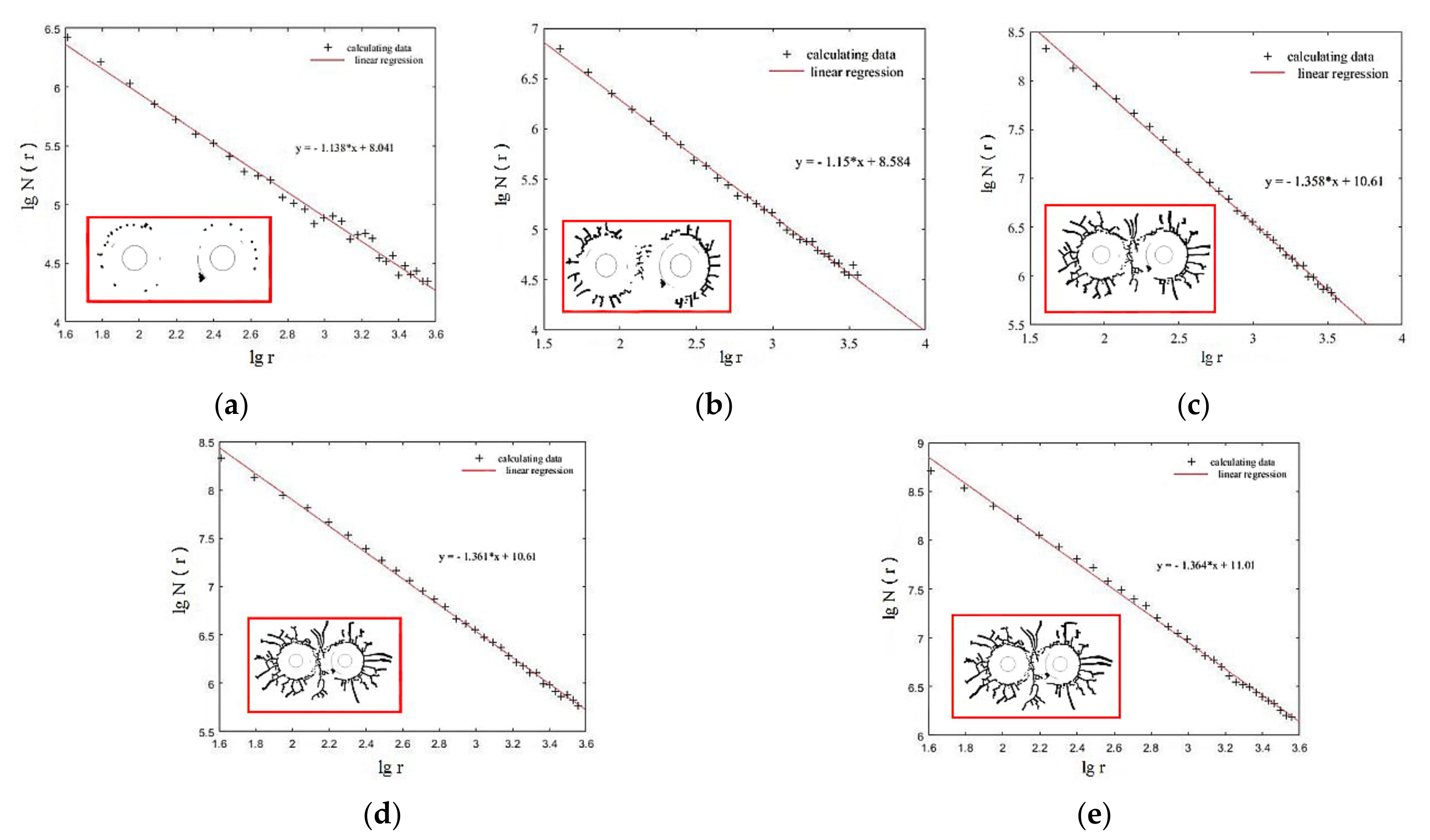
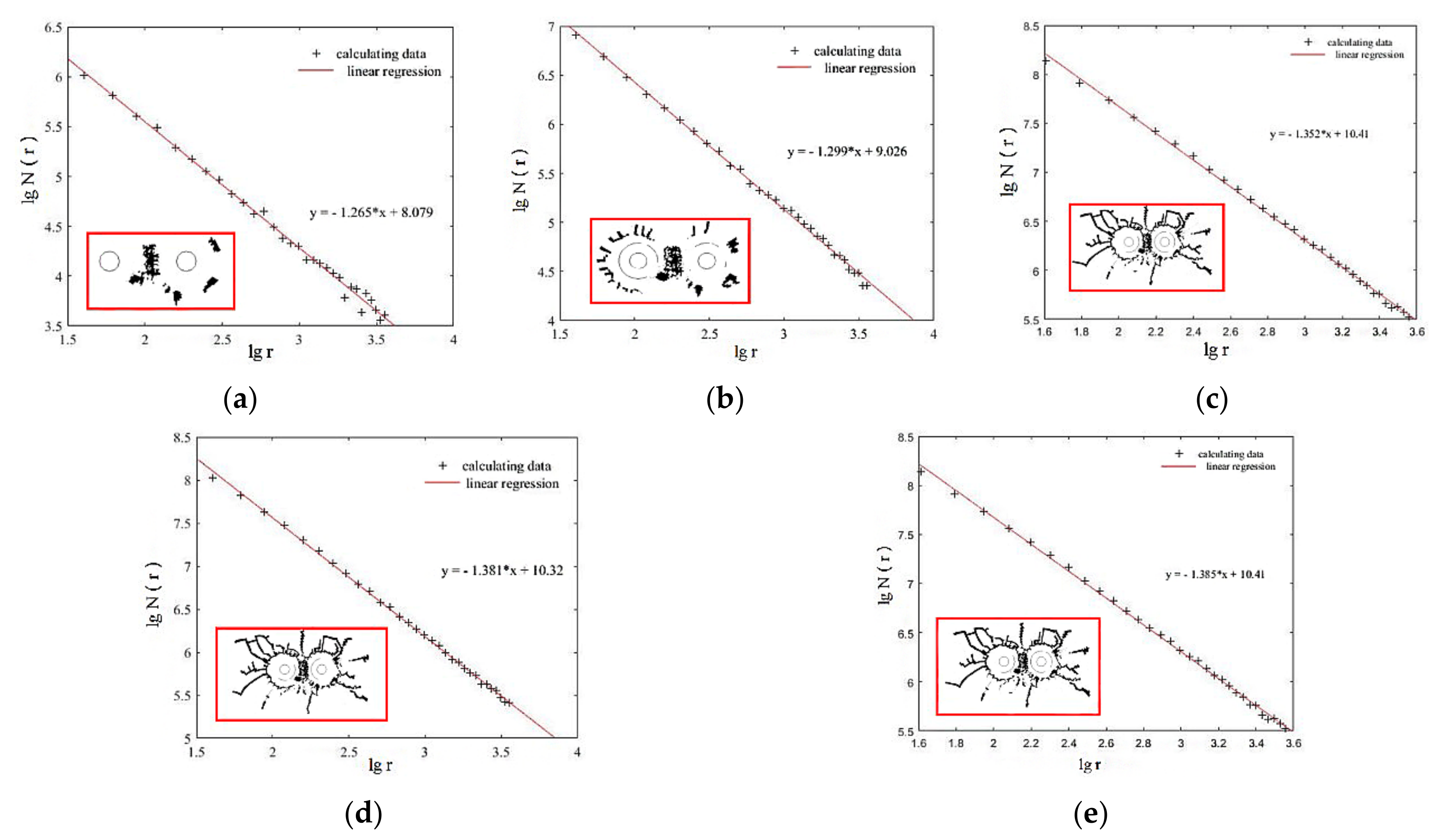
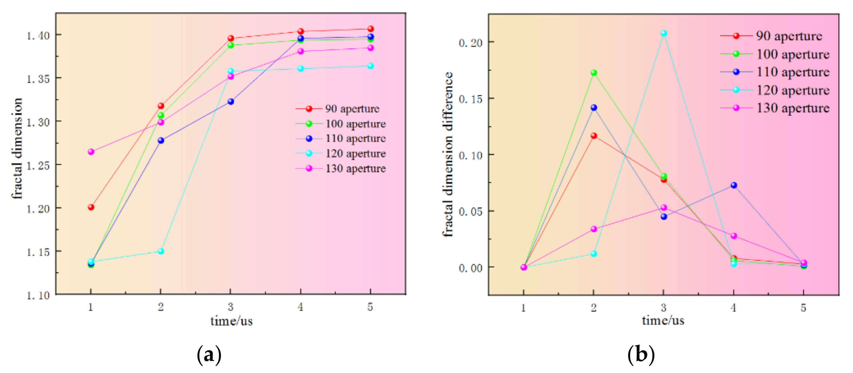
  • Based on the tensile and compressive damage model proposed in this paper, the fractal theory was introduced to further elaborate the damage characteristics of rock under blasting load. With the increase in shock wave propagation distance and propagation time, the energy gradually weakened, the crack growth rate decreased, and the crack density growth rate decreased. At the early stages after initiation, the crack density of 90 aperture and 130 aperture was larger than that of other working conditions, and the crack density of 130 aperture was the largest, followed by 90 aperture. In the middle stage after initiation, obvious cracks were formed around the two blastholes; at the end of initiation, the shock wave front decreased rapidly and continued to propagate outward in the form of a compression wave; the crack propagation velocity was much smaller than that at the early and middle stages after initiation.

Author Contributions

Conceptualization, H.S. and Z.W.; methodology, S.M.; software, Z.W.; validation, H.S. and S.M.; formal analysis, Z.W.; investigation, H.S.; resources, Z.W.; data curation, Z.W.; writing—original draft preparation, H.S.; writing—review and editing, S.M.; funding acquisition, H.S. All authors have read and agreed to the published version of the manuscript.

Funding

This project was studied by Qiandi Mining Association [2021]16; Growth Project of Young Scientific and Technological Talents in Colleges and Universities of Guizhou Province [2021]108.

Institutional Review Board Statement

Not applicable.

Informed Consent Statement

Not applicable.

Data Availability Statement

Data available on request due to restrictions, e.g., privacy or ethical. The data presented in this study are available on request from the corresponding author.

Conflicts of Interest

The authors declare no conflict of interest.

References

  1. Tatone, B.S.A.; Abdelaziz, A.; Grasselli, G. Novel Mechanical Classification Method of Rock Based on the Uniaxial Compressive Strength and Brazilian Disc Strength. Rock Mech. Rock Eng. 2022, 55, 2503–2507. [Google Scholar]
  2. Wei, J.; Zhou, J.; Song, J.-J.; Chen, Y.; Kulatilake, P.H.S.W. Estimation of tensile strength and moduli of a tension-compression bi-modular rock. Geomech. Eng. 2021, 24, 349–358. [Google Scholar]
  3. Grady, D.E.; Kipp, M.E. Continuum modeling of explosive fracture in oil shale. Int. J. Rock Mech. Min. Sci. Geomech. Abstr. 1980, 17, 147–157. [Google Scholar]
  4. Taylor, L.M.; Chen, E.P.; Kuszmau, J.S. Microcrack-induced damage accumulation in brittle rock under dynamic loading. Comput. Methods Appl. Mech. Eng. 1986, 55, 301–320. [Google Scholar] [CrossRef]
  5. Budiansky, B.; O’connell, R.J. Elastic moduli of acracked solid. Int. J. Solids Struct. 1976, 12, 81–97. [Google Scholar] [CrossRef]
  6. Kuszmaul, J.S. A new constitution model for fragmentation of rock under dynamic loading. In Proceedings of the 2nd International Symposium on Rock Fragmentation by Blasting, Keystone, CO, USA, 23–26 August 1987; pp. 412–423. [Google Scholar]
  7. Hu, Y.; Lu, W.; Chen, M.; Yan, P.; Zhou, C. Comparison and improvement of blasting damage models for rock. Rock Soil Mech. 2012, 33, 3278–3284. [Google Scholar]
  8. Thorne, B.J.; Hommert, P.J.; Brown, B. Experimentaland computational investigation of the fundamentalmechanisms of cratering. Int. J. Rock Mech. Min. Sci. Geomech. Abstr. 1992, 29, 309. [Google Scholar]
  9. Yang, R.; Brwden, W.F.; Katsabanis, P.D. A new constitutive model for blast damage. Int. J. Rock Mech. Min. Sci. 1996, 33, 245–254. [Google Scholar] [CrossRef]
  10. Hu, X.; Qu, S.; Li, K. Study on elastoplastic damage model of rock based on unified strength theory. J. China Univ. Min. Technol. 2019, 48, 305–312. [Google Scholar]
  11. Sun, Z.; Yu, Q.; Yang, J. Numerical simulation of bench blasting vibration based on continuous damage constitutive model. J. Mil. Eng. 2016, 37, 232–235. [Google Scholar]
  12. Xu, M.; Jiang, M.; Jiang, T.; Zhang, Z.; Yu, H. Hoek-Brown elastoplastic damage model considering cyclic blasting effect and its engineering application. Rock Mech. Eng. 2020, 39, 2683–2692. [Google Scholar]
  13. Liu, L.; Katsabanis, P.D. Development of acontinuum damage model for blasting analysis. Int. J. Rock Mech. Min. 1997, 34, 217–231. [Google Scholar] [CrossRef]
  14. Yang, R.; Xu, P. Fractal study of media damageunder blasting loading. J. China Coal Soc. 2017, 42, 3065–3071. [Google Scholar]
  15. Xie, F.; Zhang, J.; Chen, J. Dynamic damage model of rock under impact loads of compression and tension. J. Cent. South Univ. Sci. Technol. 2019, 50, 420–427. [Google Scholar]
  16. Liu, Y.; Yang, G.; Wang, J.-X.; Jiang, A.-N. Mohr-Coulomb elastoplastic damage constitutive model of rockand implicit return mapping algorithm in principal stressspace. Rock Soil Mech. 2017, 38, 418–428. [Google Scholar]
  17. Zhang, W.; Wang, J.; Fu, H. Damage Mechanics Fundamentals of Geotechnical Engineering; Science Press: Beijing, China, 2018; pp. 55–71. [Google Scholar]
  18. Liang, R.; Zhou, W.; Yu, J.; Li, Z.; Du, C.; Wang, D. Numerical simulation of rock tension-compression fracture caused by impact load during slope casting blast. Chin. J. High Press. Phys. 2019, 33, 82–91. [Google Scholar]
  19. Cao, W.; Lin, X.; Zhang, C.; Yang, S. A statistical damage simulation method of dynamic deformation process for rocks based on nonlinear dynamic strength criterion. Chin. J. Rock Mech. Eng. 2017, 36, 794–802. [Google Scholar]
  20. Chen, J.; Zhang, J.; Li, X. Model of rock blasting-induced damage and its application based on the integrity of rock mass. Chin. J. Geotech. Eng. 2016, 38, 857–866. [Google Scholar]
  21. Shan, R.; Song, L.; Bai, Y.; Song, Y.; Li, Z.; Wei, L.; Cao, J. Model test study on damage assessment of frozen rock wall under blasting. Rock Mech. Eng. 2014, 33, 1945–1952. [Google Scholar]
Figure 1. Field blasting and acoustic wave layout diagram.
Energies 15 06194 g001
Figure 2. Schematic diagram of test area.
Energies 15 06194 g002
Figure 3. Blasting rupture range based on the proposed damage model.
Energies 15 06194 g003
Figure 4. Comparison of numerical results and measured results of blasting rupture range [9,13].
Energies 15 06194 g004
Figure 5. The 90 mm aperture, 630 mm aperture fractal dimension and damage evolution process. (a) At 1 us after explosion; (b) 2 us after explosion; (c) 3 us after explosion; (d) 4 us after explosion; (e) 5 us after explosion.
Energies 15 06194 g005
Figure 6. The 100 mm aperture, 700 mm aperture fractal dimension and damage evolution process. (a) At 1 us after explosion; (b) 2 us after explosion; (c) 3 us after explosion; (d) 4 us after explosion; (e) 5 us after explosion.
Energies 15 06194 g006
Figure 7. The 110 mm aperture, 770 mm aperture fractal dimension and damage evolution process. (a) At 1 us after explosion; (b) 2 us after explosion; (c) 3 us after explosion; (d) 4 us after explosion; (e) 5 us after explosion.
Energies 15 06194 g007
Figure 8. The 120 mm aperture, 840 mm aperture fractal dimension and damage evolution process. (a) At 1 us after explosion; (b) 2 us after explosion; (c) 3 us after explosion; (d) 4 us after explosion; (e) 5 us after explosion.
Energies 15 06194 g008
Figure 9. The 130 mm aperture, 910 mm aperture fractal dimension and damage evolution process. (a) At 1 us after explosion; (b) 2 us after explosion; (c) 3 us after explosion; (d) 4 us after explosion; (e) 5 us after explosion.
Energies 15 06194 g009
Figure 10. Variation of fractal dimension of each aperture. (a) Fractal dimension of each aperture; (b) Dimension difference of each aperture.
Energies 15 06194 g010
Table 1. Maximum fracture radius.
Research MethodMaximum Rupture Radius Rmax/mDeviation between Each Method and Actual Measurement
Based on the damage model proposed in this paper1.630.09
Damage model based on Reference [13]1.850.15
Damage model based on Reference [9]1.570.13
Field test1.72×
Table 2. Bottom fracture depth.
Research MethodBottom Hole Rupture Depth Hmax/mDeviation between Each Method and Actual Measurement
Based on the damage model proposed in this paper0.860.04
Damage model based on Reference [13]0.760.06
Damage model based on Reference [9]0.940.12
Field test0.82×
Publisher’s Note: MDPI stays neutral with regard to jurisdictional claims in published maps and institutional affiliations.

