Article

Analysis and Verification of Leakage Inductance Calculation in DAB Converters Based on High-Frequency Toroidal Transformers under Different Design Scenarios

1
Department of Electrical Engineering, NUST College of Electrical and Mechanical Engineering, National University of Sciences and Technology, Islamabad 44000, Pakistan
2
Department of Electrical Engineering College of Engineering, TAIF University, Taif 11099, Saudi Arabia
3
School of Computing, Engineering and the Built Environment C011, Glasgow Caledonian University, 70 Cowcaddens Rd., Glasgow G4 0BA, UK
*
Author to whom correspondence should be addressed.
Energies 2022, 15(17), 6176; https://doi.org/10.3390/en15176176
Submission received: 3 August 2022 / Revised: 23 August 2022 / Accepted: 23 August 2022 / Published: 25 August 2022

Abstract

:
High-frequency transformers are becoming an essential component in the integration of power resources that rely on power electronic converters; their efficiency and performance are influenced by parasitic characteristics in the interface. In this article, the design of a high-frequency toroidal transformer has been explained in detail using the ANSYS Maxwell platform. Various parameters, such as leakage inductance, magnetic flux density, magnetic field strength and uniform magnetic flux line are analyzed using Finite element analysis. High-frequency transformers using a toroidal core with different winding configurations are examined and all parameters obtained through simulation are validated by an analytical approach. Analysis of each design is based on its leakage inductances, which will aid in the appropriate selection of transformers as a function of their operating frequency. This analysis is expected to guide designers to optimize the high-frequency transformer parameters based on practical applications. The optimized parameters are then applied for a dual active bridge (DAB) converter within MATLAB/Simulink to verify the design process. A prototype has been built to validate the simulation and design procedure. The results obtained from both simulation and experiments are compared and show great correlation.

1. Introduction

High-power densities have become a design requirement for power conversion units, especially in high-restriction applications, such as offshore wind farms and traction systems [1]. To accomplish this objective, heavy low-frequency transformers should be altered with high-power DC-DC converters comprised of lightweight and compact high-frequency transformers. However, when subjected to higher frequencies, one must contend with additional losses due to the eddy current in the magnetic core [2], winding losses due to enhanced skin and proximity effects [3], and parasitic elements, such as winding capacitance and leakage inductance [4] producing excess switching losses, which are typically foremost at higher frequencies [5].
Dual active bridge (DAB) converters are becoming extremely popular for use in high-power applications [6]. Figure 1 depicts the equivalent circuit of a DAB converter in which the output signal of the input and output bridges is a square wave form with a nominal phase shift. This provides voltage to the inductance LK, which is utilized as a power transfer element to shape the current [7]. To accomplish zero-voltage switching (ZVS), the phase shift between the bridges must be greater than a specified value [8], which results in a minimum value for the series inductance calculated as:
L k = V D C × V o u t 2 × π × f s × P o u t x   n s i n
where VDC and Vout are the input and output DC voltages, respectively, and is the phase shift between the primary and secondary voltages of the high-frequency transformer depicted as the key element of the DAB converter and is the ratio of the primary voltage to the secondary voltage. Pout is the intended output power, n is the number of turns of the high-frequency transformer, and fs is the operating frequency, also known as the switching frequency.
This inductance, as seen in Figure 1, may be viewed as an integrated leakage inductance, Lk, in the high-frequency transformer, allowing for a reduction in the number and size of components [9]. Consequently, it is crucial to precisely estimate the leakage inductance of a transformer during the design phase, as an inadequate leakage inductance causes a shift in the soft-switching area, which might have a negative impact on the converter’s efficiency. Similarly, high-leakage inductance is undesirable since it results in an undesired reactive power circulation inside the converter, which ultimately reduces the converter’s efficiency and output active power, but can widen the soft-switching zone to some extent.
Leakage inductance is a small inductive element which occurs due to improper coupling of flux between one winding and the other. Leakage inductances play a vital role in switching-based power supply resulting in less switching current in the device and the energy stored in it results in switch voltage spikes. Similarly, due to creation of EMI, switching losses increase and hence efficiency of the system decreases [10,11,12,13]. Furthermore, parasitic capacitances cause the infusion of currents due to high frequency, hence amplifying electromagnetic interferences (EMI) and can establish electrostatic connection with other circuit components. The system’s switching waveforms and efficiency can be improved by reducing two parameters, i.e., parasitic capacitance and leakage inductance [14]. Switching frequency in modern technologies is increasing from kHz to MHz in order to minimize the size of inductive components and accurately estimate the high-frequency leakage inductance necessary for the appropriate design of a system. This is done in order to fulfil the requirements of the proper design of a system [15].
Several research articles have been published on the calculation and analysis of leakage inductance on the planer and conventional core-type or shell-type transformer [16,17,18,19,20,21,22,23]. However, the major problem in these articles is the operation at low frequency. It is being concluded in most of the cases that leakage inductance is independent of frequency and current which is uniformly distributed. In fact, leakage inductance is reduced when frequency is increased [24].
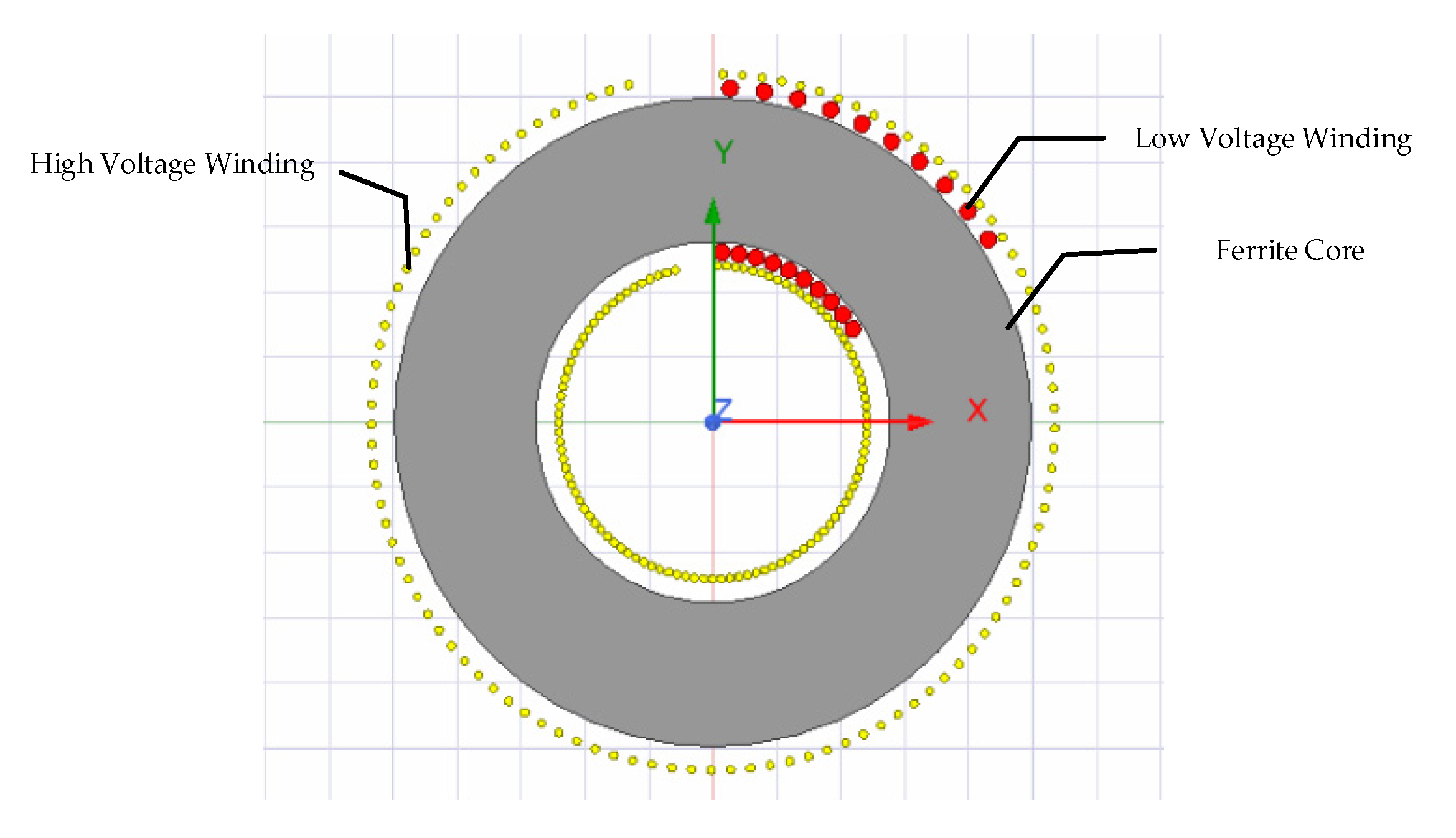
The size of passive components reduces with increase in frequency and hence help in the downsizing of a transformer. However, at higher frequencies, the parasitic components become dominant and accurate calculation of the parasitic parameters is required to achieve better results in resonant converters. Undesirable leakage inductances and parasitic capacitances can disrupt the design and create unwanted resonant frequencies, leading to voltage and current waveform distortion and reduced efficiency. This may also cause a disruption in the control system [25]. High-frequency transformer design is a key step for proper working of isolated DC-DC choppers and appropriate core geometry and winding arrangements must be adopted to manage the factors depending upon its applications. Various transformer core geometries and winding configurations result in varying parasitic characteristics. It is vital to comprehend the parasitic parameters of different transformers and their applications require optimizing of these parasitic parameters [26,27]. Figure 2 depicts the schematic diagram of a single-phase 2D toroidal transformer.
In this article, the design of a toroidal transformer is conducted using ANSYS-Maxwell software, 2022 R2, (licensed for NUST, Pakistan) to recognize an FEM-based solution for various transformers. The main objective of this study is to design a high-frequency toroidal transformer in ANSYS-Maxwell, study the leakage inductance of different configurations of windings and use the designed toroidal transformer in a DAB converter.
Scope of the research article:
The scope of this research work is as follows:
  • A high-frequency toroidal transformer is developed using FEM instead of a shell-type or core-type for a dual active bridge (DAB) converter.
  • Leakage inductance is a major factor in reducing the power transfer in the DAB converter, therefore leakage inductance as a function of frequency is studied under different scenarios and minimized leakage inductance is obtained.
  • Other parameters, such as magnetic field lines, magnetic flux density and intensity are discussed and compared with the shell-type transformer. As a result, the best possible uniform parameters are obtained in the case of the toroidal transformer.
  • A reduced leakage-inductance-based toroidal transformer is used in a DAB converter and the simulated results are validated with the help of an experimental prototype.

2. Design of a Toroidal Transformer Using ANSYS Maxwell

2.1. ANSYS-Electromagnetic

Transformers, motors, leakage-fluxes, magnetic fluxes and thermal calculations, design, electromagnetic and electromechanical analyses of 2D and 3D devices along with sensors and coils, were performed using the electromagnetic solvent of the design tools. ANSYS MAXWELL was used to investigate the magnetic and electric fields whose static frequency domain was not uniform. Built-in functionality of ANSYS MAXWELL, namely PExprt modeler, allowed us to define the toroidal core geometry and its winding configuration and further analysis was performed within the design tool.
As stated in [28], the electromagnetic model’s essential relationship is associated with four field vectors: magnetic field intensity H, electric field intensity E, magnetic flux density B and electric flux density D. Maxwell’s equations are the set of mathematical equations that are consistent with the equation of continuity in a time-varying domain of an electromagnetic field. They are based on partial differential equations, and each fundamental vector E, D, B, H contains three components corresponding with the three-dimensional space. The solution of Maxwell’s equations is complicated due to its size and form, but can be achieved by applying the FEM.
The ANSYS MAXWELL platform also provided the ANSYS-PExprt and ANSYS-RMxprt design tools for the design of transformer and motors, respectively. The capability to build designs for use in ANSYS-Simplorer is a key feature of the ANSYS MAXWELL software. This trait generates a strong electromagnetic-based design flow that enables the combination of sophisticated designs with Maxwell’s precise component-models.

2.2. Core Selection

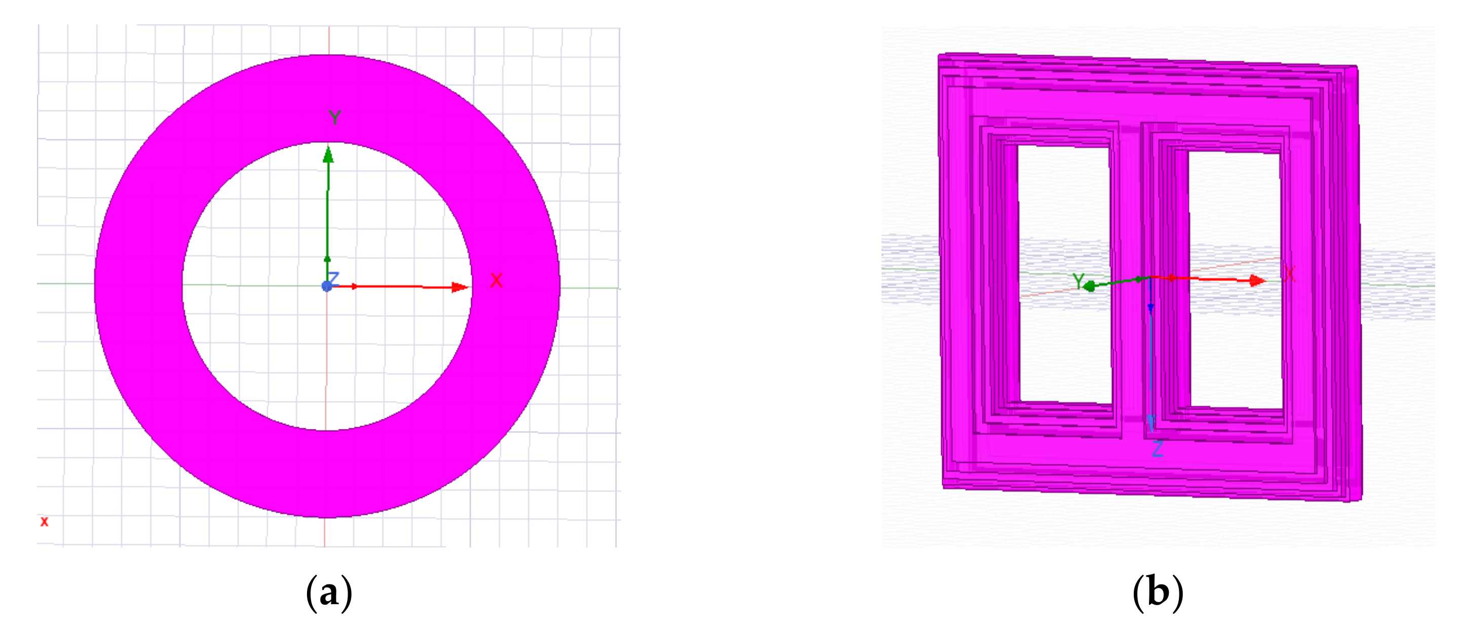
The selection of a transformer’s magnetic core and material is an important stage in the design of high-frequency transformers for power electronics applications. Three primary considerations influence the magnetic material used in any design i.e., cost, performance and size. These variables are impacted by factors, such as relative permeability, core loss, and stability due to temperature and so on. Magnetic materials may be utilized in power electronic equipment, and designers must make a trade-off when selecting materials for each application. The core to be utilized is first chosen, and then its geometric features are defined [29]. The core shapes for toroidal and shell-type are given in Figure 3.

2.3. Design of Windings

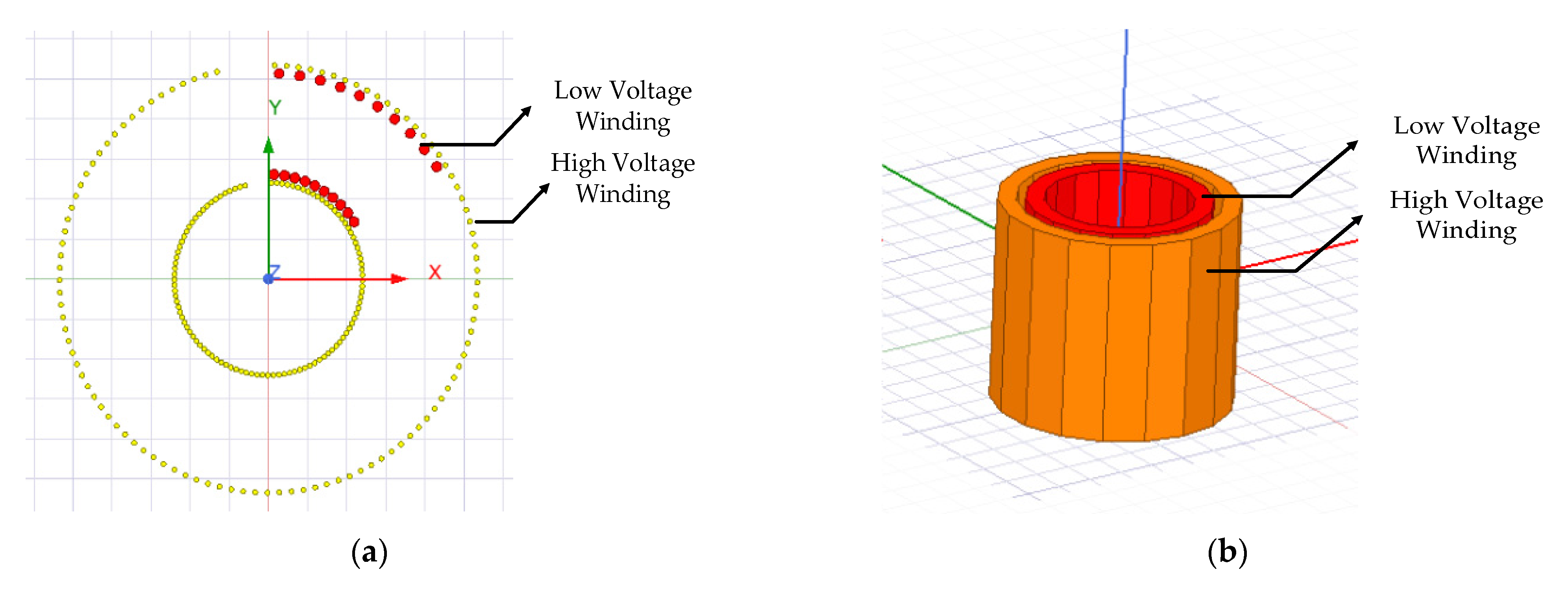
Transformers employ concentrated winding, which means that each limb of the core must contain a coil and its consequent terminal. Since the design is a single-phase transformer, the coil design of the shell-type is only for one leg, as illustrated in Figure 4b. After the design of the windings, the geometric characteristics of the windings are calculated [30]. Figure 4 depicts the windings design for toroidal and shell-type cores.

3. ANSYS Maxwell Simulations of Toroidal Transformer

In this section, FEA simulations of various toroidal transformer are presented. Different distributions of windings were assigned to a toroidal core. Transformers have primary and secondary windings made of various wire gauges based on current (A) rating and for different numbers of turns.

3.1. Parametric Analysis of Toroidal Core Transformer

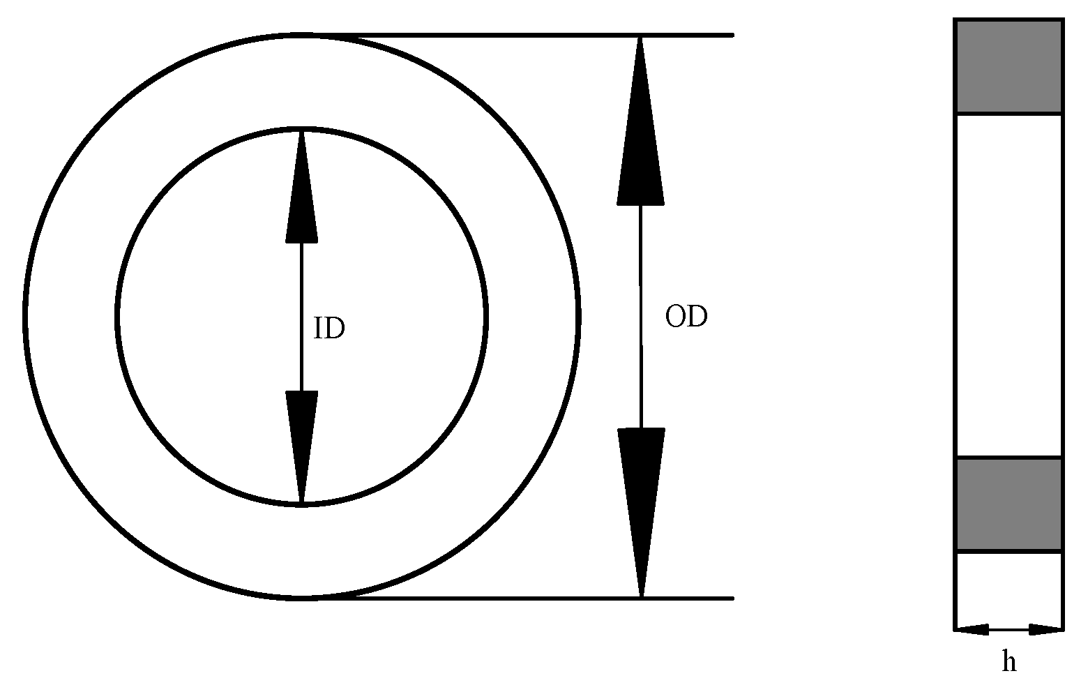
Figure 5 depicts the magnetic core dimension, while Table 1 summarizes the geometric dimensions and features. Equations (2) and (3) may be used to compute the effective area and effective length of the toroidal core, respectively.
A c o r e T o r o i d a l = h   O D     I D 2
l c o r e t o r o i d a l = π   O D + I D 2
where Acore(Toroidal), lcore(Toroidal) represents the area of the toroidal core and the length, respectively, OD signifies the outer diameter, ID signifies the inner diameter, and h represents the core height.
Similarly, the Area of the core depends upon frequency, flux density and turns per volts (Te) and is given by [31];
A c o r e = 1 4.44 × f × B m a x × T e
where,
f is the operating frequency in Hz,
Bmax is the magnetic flux density in Tesla, and
Te is the number of turns per volts.
Primary and secondary currents in the design play an essential role. Since current i flows in the primary and secondary side of a transformer, the current is obtained as;
i = S V o l t a g e   V
where,
i presents the effective current in A flowing through the winding,
S is the apparent power rated in VA, while
V presents the effective winding voltage.
If the design also includes efficiency (η), then (5) can be revised as;
i = S η × V
where,
η is the efficiency of a transformer.
Furthermore, number of turns on the primary and secondary side can be observed as;
N = t u r n s   p e r   v o l t s × v o l t a g e
The selection of wire can be done by calculating the current and by crossmatching the standard table of copper wire according to this current handling capability. Table 2 provides the design summary of a transformer.
The windings around the toroidal core can be dispersed in a variety of ways. Each winding distribution alters the transformer’s leakage inductance, permitting modifications to be made to achieve the required inductance value. The distance between the core and primary windings, the distance between the windings, and the location of the windings in the core circumference with and without overlapping are some of the geometrical variables that may be purposefully adjusted. Additional configuration scenarios and their results are presented in [30].

3.2. Material Determination of Cores and Coils

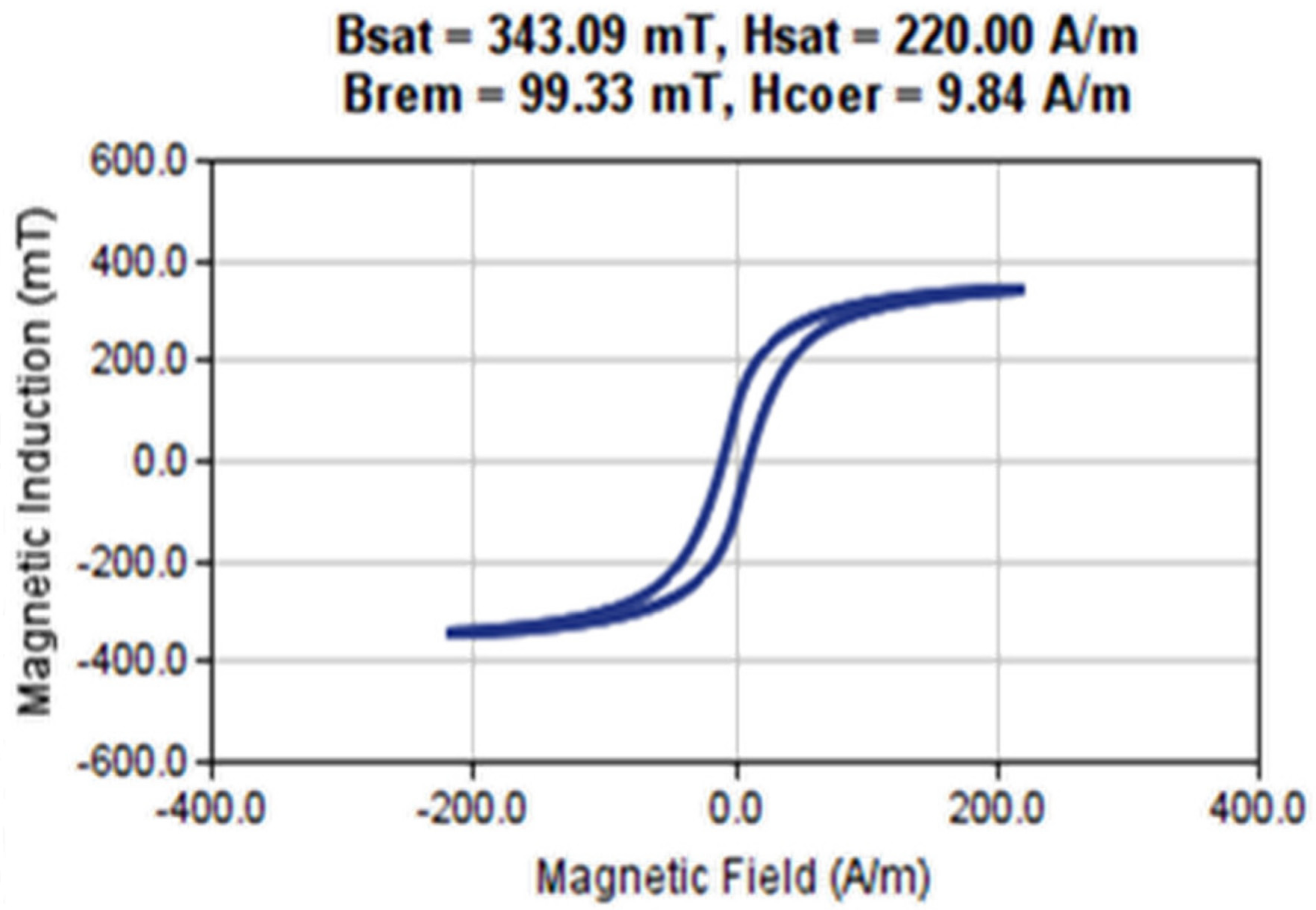
The necessary step in material determination is to specify the sort of vacuum zone as well as the constituents used to construct the intended model. “Assign Material” is an option used for the specification of the materials. Allotment of Material for windings or the core can be created with the program using “Add material” from the library. Copper is used for winding in this article while the core is of ferrite material. Figure 6 represents the material’s hysteresis curves.

3.3. Mesh Configuration

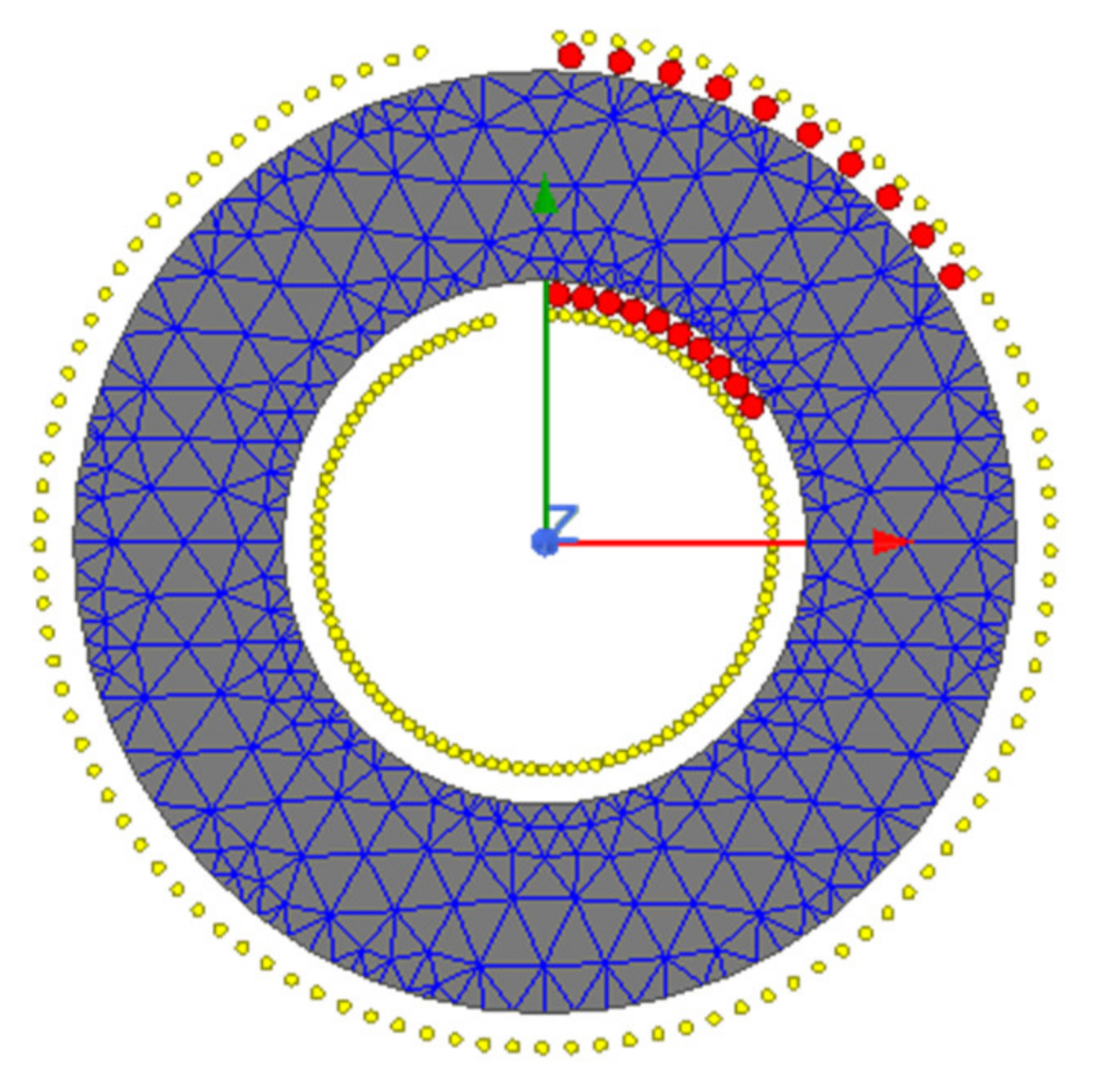
The tool automatically generates a network based on the model created in the ANSYS MAXWELL software. Following the creation of the network, a field solution is generated for each model. If meshing is not done, system-generated results are inaccurate, which may be misleading for practical design. Meshing requires segmentation of the core into smaller areas for finite element analysis and the appropriate result is achieved by raising the mesh number [24]. The findings of the simulation produced from the analysis become highly realistic as the mesh number of the model increases but in parallel simulation time increases. The number of mesh elements used for the design is 1000. Mesh configuration is illustrated in Figure 7.

4. Transformer’s Magnetic Flux Density, Intensity and Flux Lines

For the steady-state scenario, analysis of a magnetic field density (B), magnetic field strength (H) and magnetic flux lines (A) of a toroidal transformer proposed in this section have been discussed. Figure 8 shows an input voltage simulation waveform for analysis.
Boundary conditions for the design of a toroidal transformer, geometric dimensions, and attributes of all materials utilized are defined in the model using the 2D environment of ANSYS MAXWELL. Table 3 shows the electrical data that was used in the transformer study and design.
Figure 9 depicts the magnetic flux density of a toroidal transformer as designed in the ANSYS MAXWELL 2D environment.
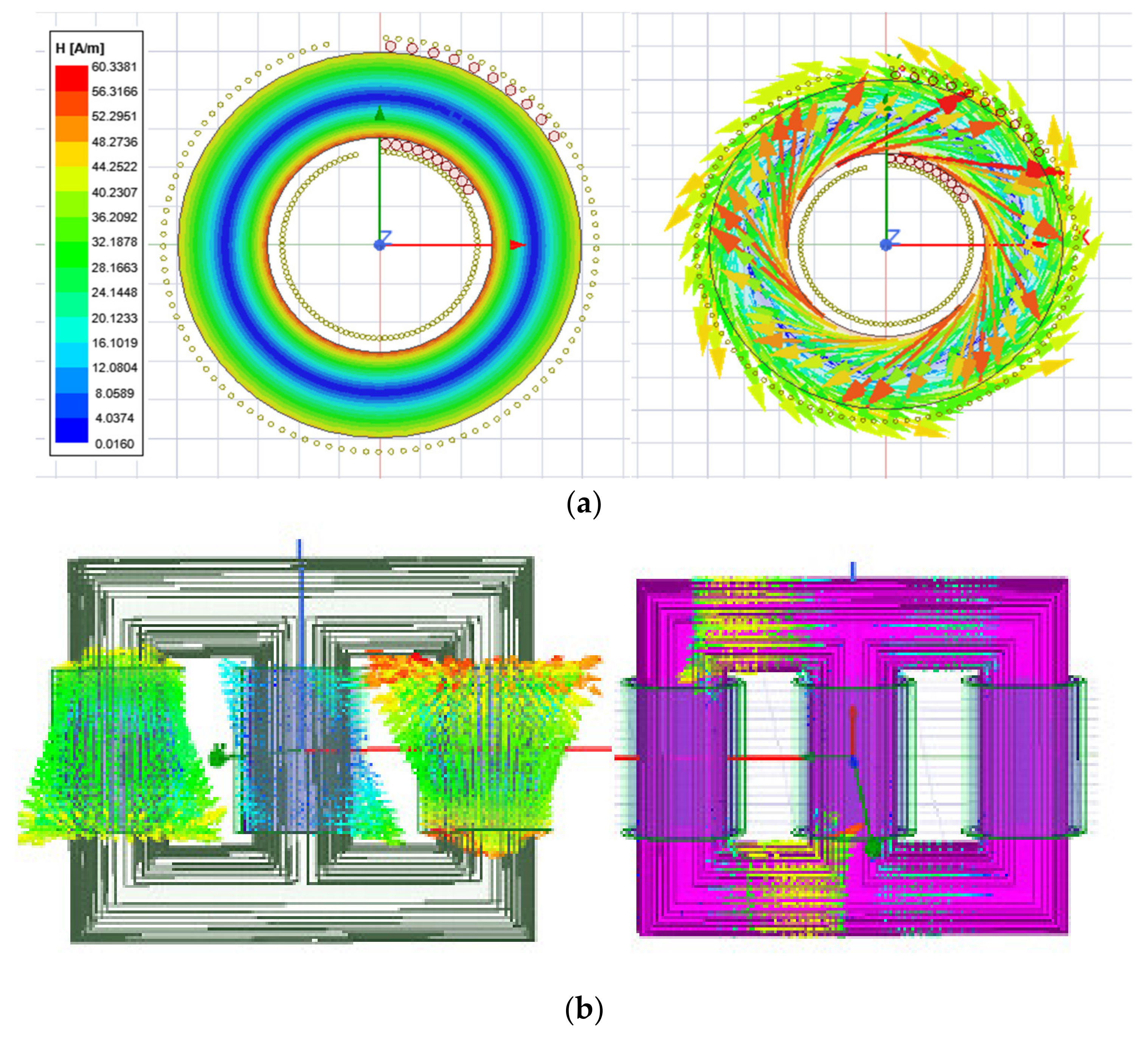
The magnetic field strength is also determined by the research study. Figure 10a depicts a high magnetic field at the core, whereas Figure 11 depicts homogenous magnetic flux lines. Excessive stress and strain on the winding is obvious from Figure 10b, which can cause insulation to degrade or even deform [32], whereas the toroidal transformer showed less winding stress compared to the shell-type.

5. Leakage Inductance of a Toroidal Transformer

To compare the computation and finite element analysis (FEA) simulation, the magnetic core of ferrite material was chosen. Using Ansys/Maxwell, the FEA simulation was conducted using 2D rotational symmetry.
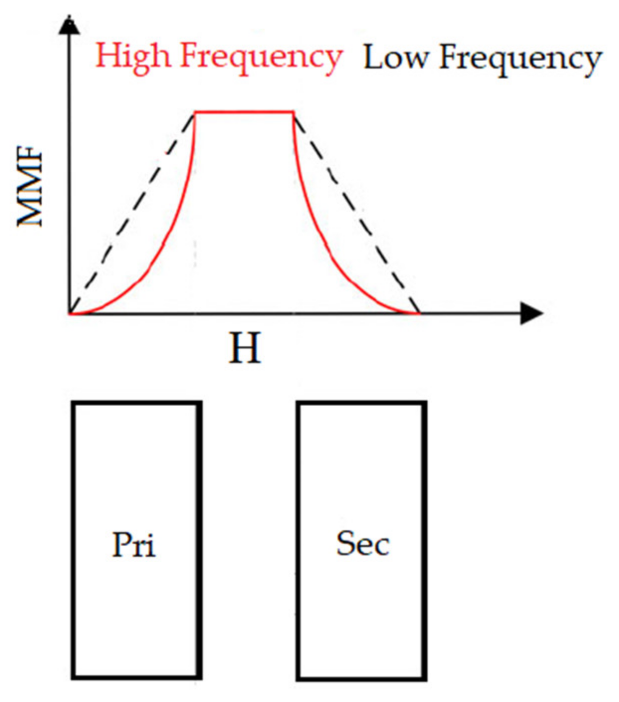
At low frequency, the magnetic field strength (H) within the conductors was linearly distributed. As the frequency increased, the high-frequency eddy current effect led the current density to be nonuniform in the cross section of the conductor, and the majority of the currents concentrated on the conductor’s surface [24]. As the number of layers grew, the proximity effect accelerated the movement of conductor currents toward the surface. As illustrated in Figure 12, the magnetic field strength (H) developed the “concave form” at high frequency, particularly for a large number of layers.
Consequently, the leakage inductance was drastically decreased as the frequency increased. Comparing the high-frequency leakage inductances of the four distinct winding layouts, parametric FEM simulations encompassing a broad range of frequencies were conducted up to 300 kHz. The resultant leakage inductances were then compared to those derived by Equations (8)–(10). The following formulae can be used to determine the leakage inductance for a DAB converter [33,34].
L k = V 1 V 2 8 f P m a x 1 d d T
Similarly, leakage inductance associated with the leakage flux of a winding can be determined by [35];
L k 1 = L 11 N p N s L M
L k 2 = L 22 N p N s L M
where,
L11 = Self-inductance of winding 1
L22 = Self-inductance of winding 2
LM = Mutual inductance due to one winding on the other.
Table 4 briefly describes the details of the toroidal transformer defined for different cases as described in detail below. High-frequency leakage inductances for the four different winding configurations were compared. DAB converter-based leakage inductance is analytically calculated using Equation (8).

5.1. Case: 1

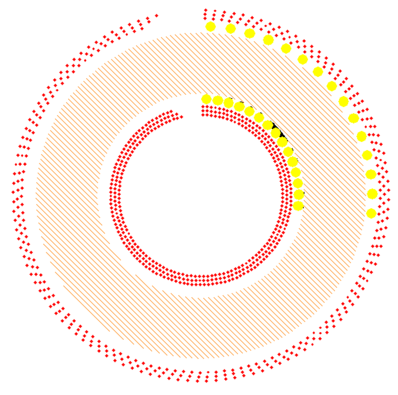
In this scenario, the current density distribution at 50 kHz and the investigated winding arrangement, illustrated in Figure 13 consisted of 5 and 120 foil conductors in the primary and secondary winding respectively, two layers and one turn per layer, with a foil thickness of 1.2 mm. All the geometrical dimensions were kept constant while the operating frequency was swept from 50 Hz to 300 kHz. An analysis was performed of the inductance behavior of overlapping windings in cases where they were not entirely distributed around the ring core, and they were not fully overlapped.
The leakage inductance waveforms in Figure 14 show more significant variation when the coils are in different situations. The individual leakage of each coil was more prominent when it was tightly wounded, and the other coil was more dispersed over the core. On the other hand, when the coils were overlapped and wound close to each other, the leakage was small, consistent with the concept that the leakage flux is intense when the turns of a winding are together, but if another winding is placed overlapping the first one, the secondary winding strongly links with the primary, decreasing its leakage flux. Leakage inductances referred to the primary side were 1.93 and 1.85 uH at 1 kHz and 1 MHz, respectively. The reduction in leakage inductance was 5%.

5.2. Case: 2

In case 2, Primary winding consisted of 15 turns while secondary turns consisted of three layers overlapping each other and contained 375 turns covering the whole core of the transformer as shown in Figure 15. Since the number of turns were 15 and 375, respectively, one turn of primary coil was placed for 25 turns of secondary coil. The distance between the core and primary and between the primary and secondary winding was the same.
The analysis of the leakage inductance graphs in Figure 16 represents more significant variation when the coils are in different situations. To cover the core of a transformer, the primary winding is increased and the secondary winding correspondingly increases. Comparing the leakage inductance of the primary side and secondary side, the leakage inductance represents that due to the less-turns ratio, the flux created on the primary results in a completely induced current on the secondary, resulting in less leakage inductance while the flux due to the secondary current results in more flux and hence less current is generated on the output, hence more leakage inductance is produced. Leakage inductance in this scenario was 6.65 at 1 kHz and 5.98 uH at 1 MHz, reducing the leakage inductance by 11%.

5.3. Case: 3

In case 3, 24 turns, covering half of the toroid core of the transformer, were winded on the primary while four layers of secondary winding contained 600 turns, as depicted in Figure 17. The leakage inductance waveform in Figure 18 gives us information about the primary flux linkage with the secondary, hence resulting in minimized leakage inductance while the flux created due to the secondary is not completely induced in the primary flux, therefore resulting in higher leakage inductance in comparison with the primary leakage inductance. Leakage inductance at 1 kHz and 1 MHz was 9.5 and 8.2 µH, respectively. The reduction was approximately 14%.
After studying various cases of the toroidal transformer, it was observed that case 3 resulted in less leakage inductance due to an increased number of turns on the primary side and an assumption can be made that proper winding, covering the area of the core and a decreased distance of winding from the core resulted in proper coupling of flux between the two windings and therefore less leakage inductance was produced.

6. Simulation Results of DAB Converter

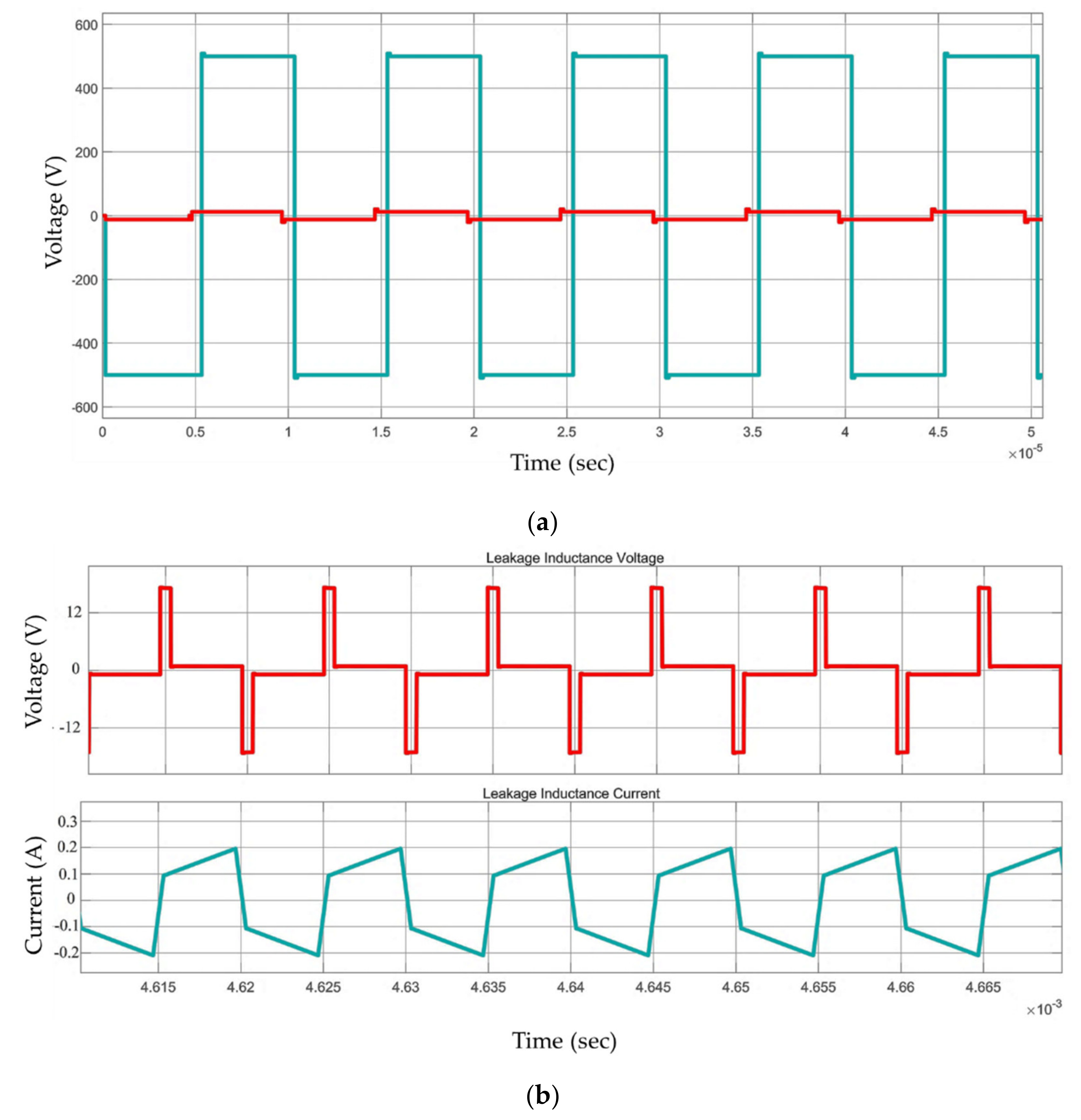
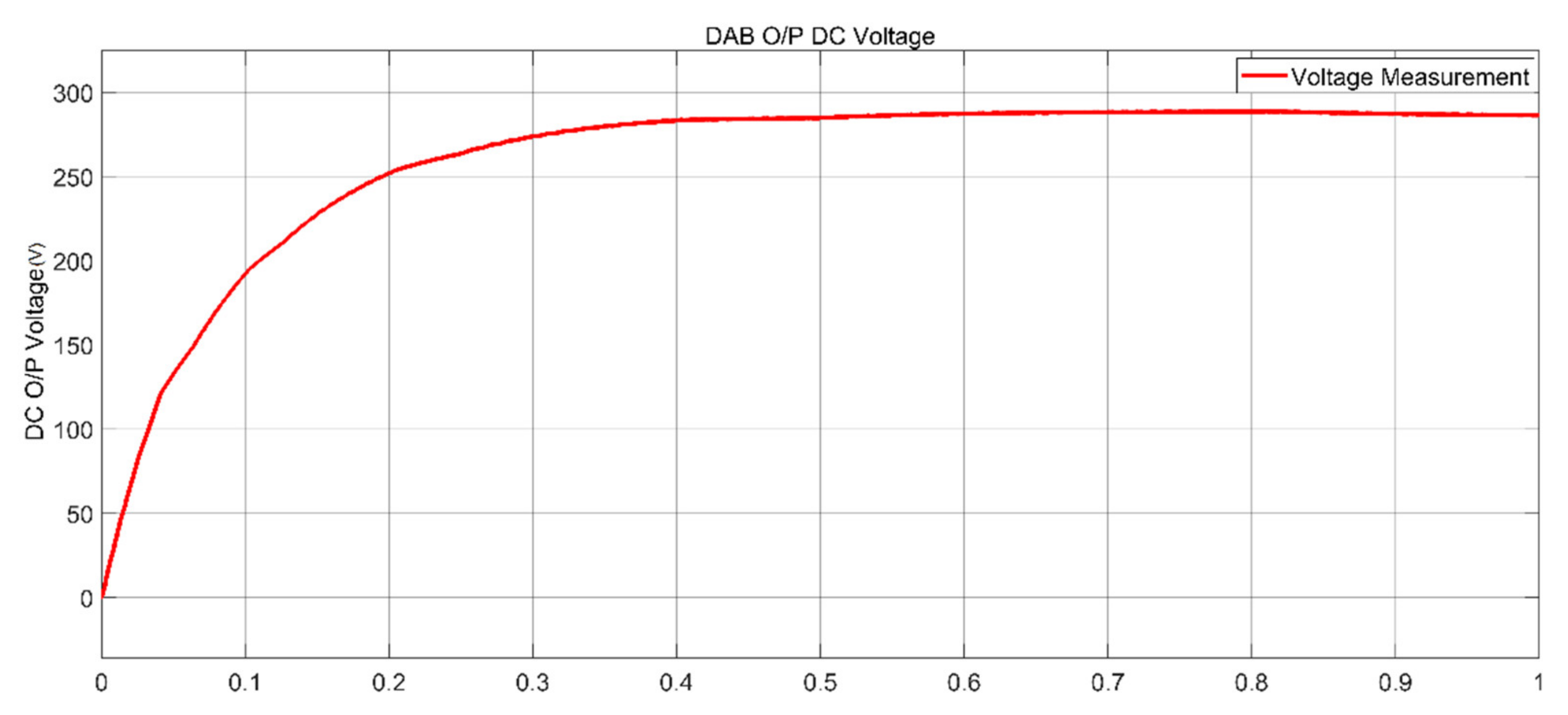
This section presents a significant waveform of the dual active bridge converter illustrated in Figure 1. Figure 19 and Figure 20 represent simulation results of a dual active bridge converter. Parameters used in the simulation and experimental setup are presented in Table 5. Vin = 12 volts was applied and the output DC voltage was kept constant to a value of V = 285.6 V, keeping a modulation index of MI = 0.85 and load RL = 100 Ω. Calculated values under SPWM are given in Table 6.
DC voltage of the DAB converter is represented in Figure 20.

7. Experimental Validation

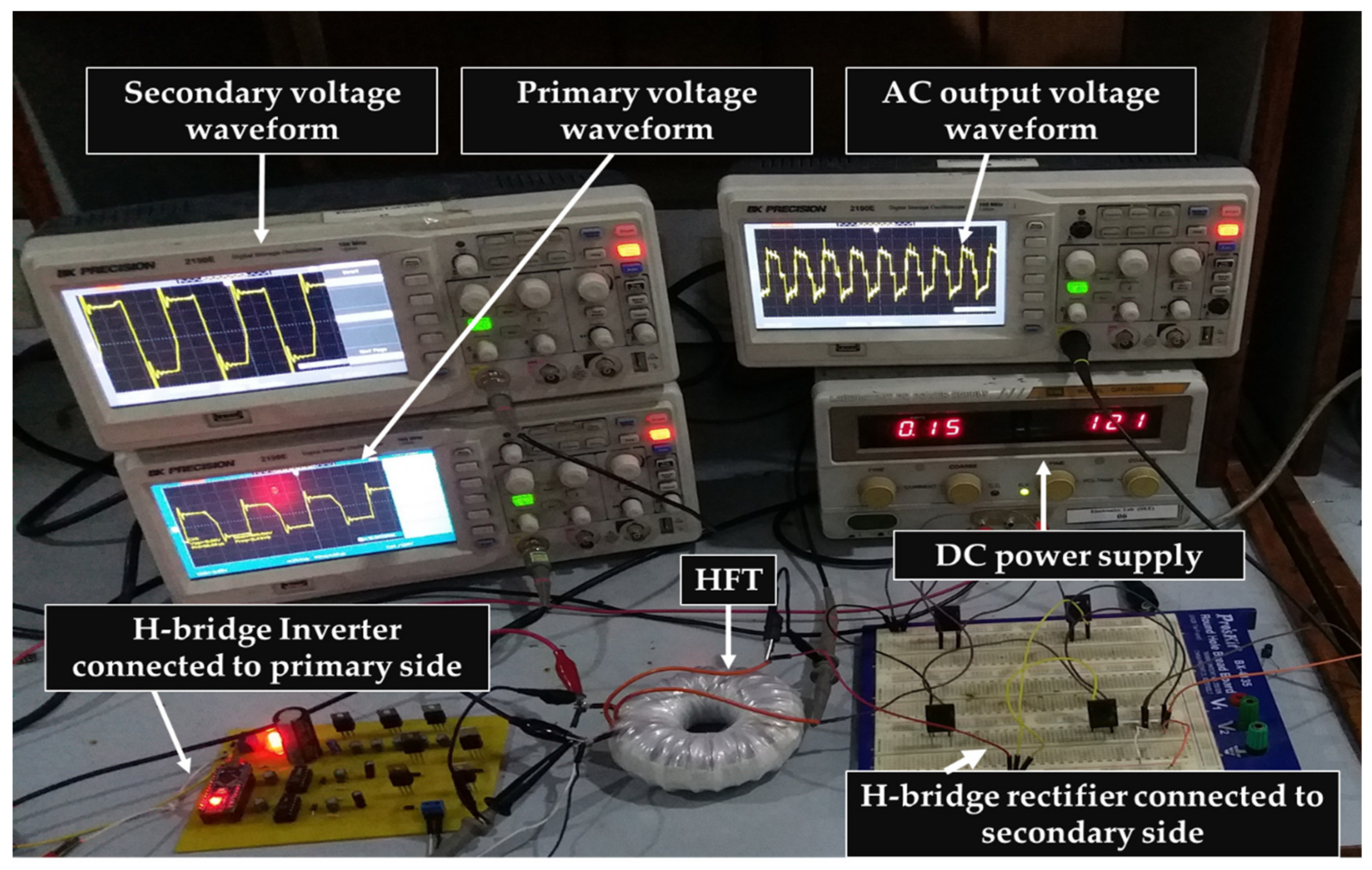
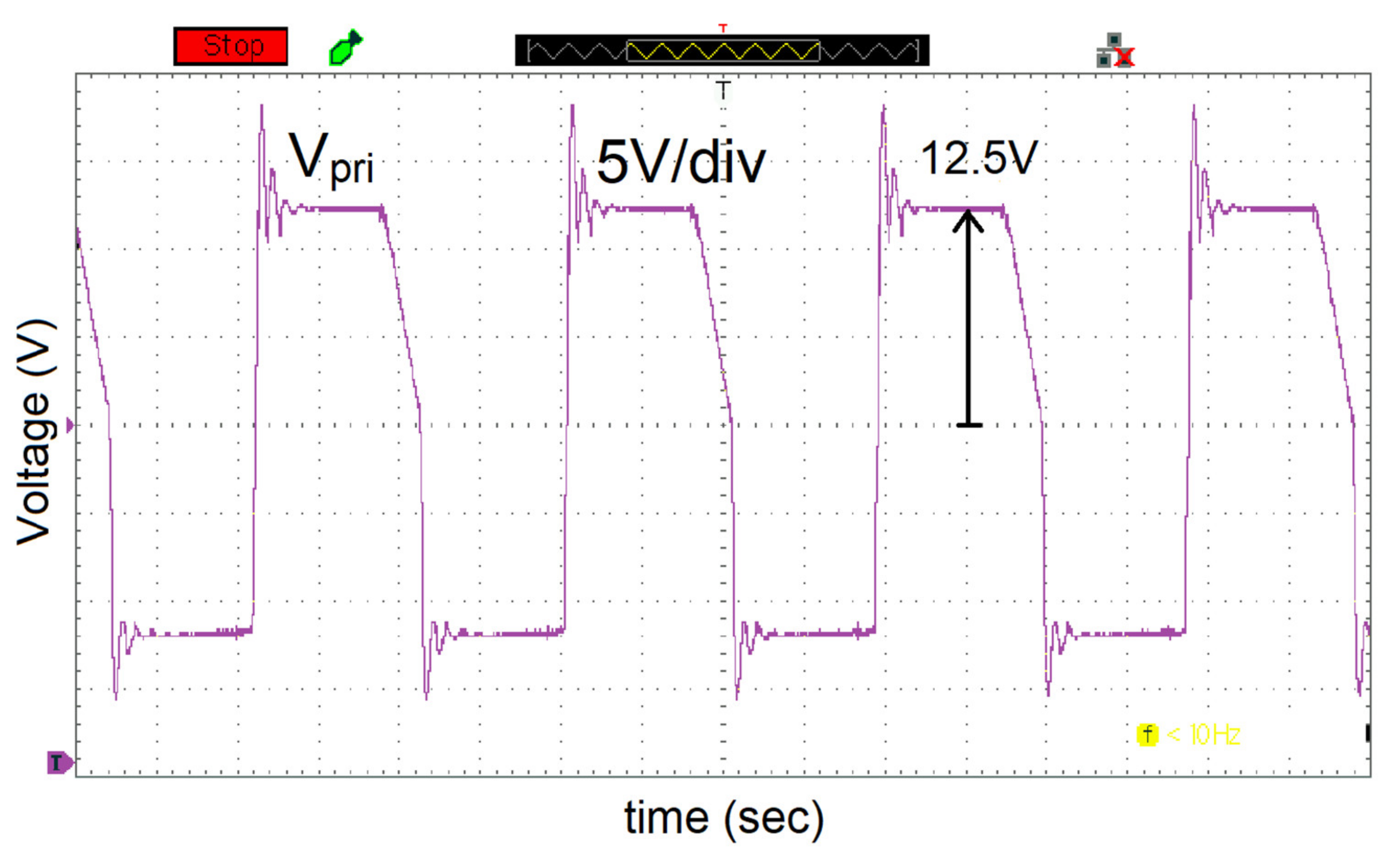
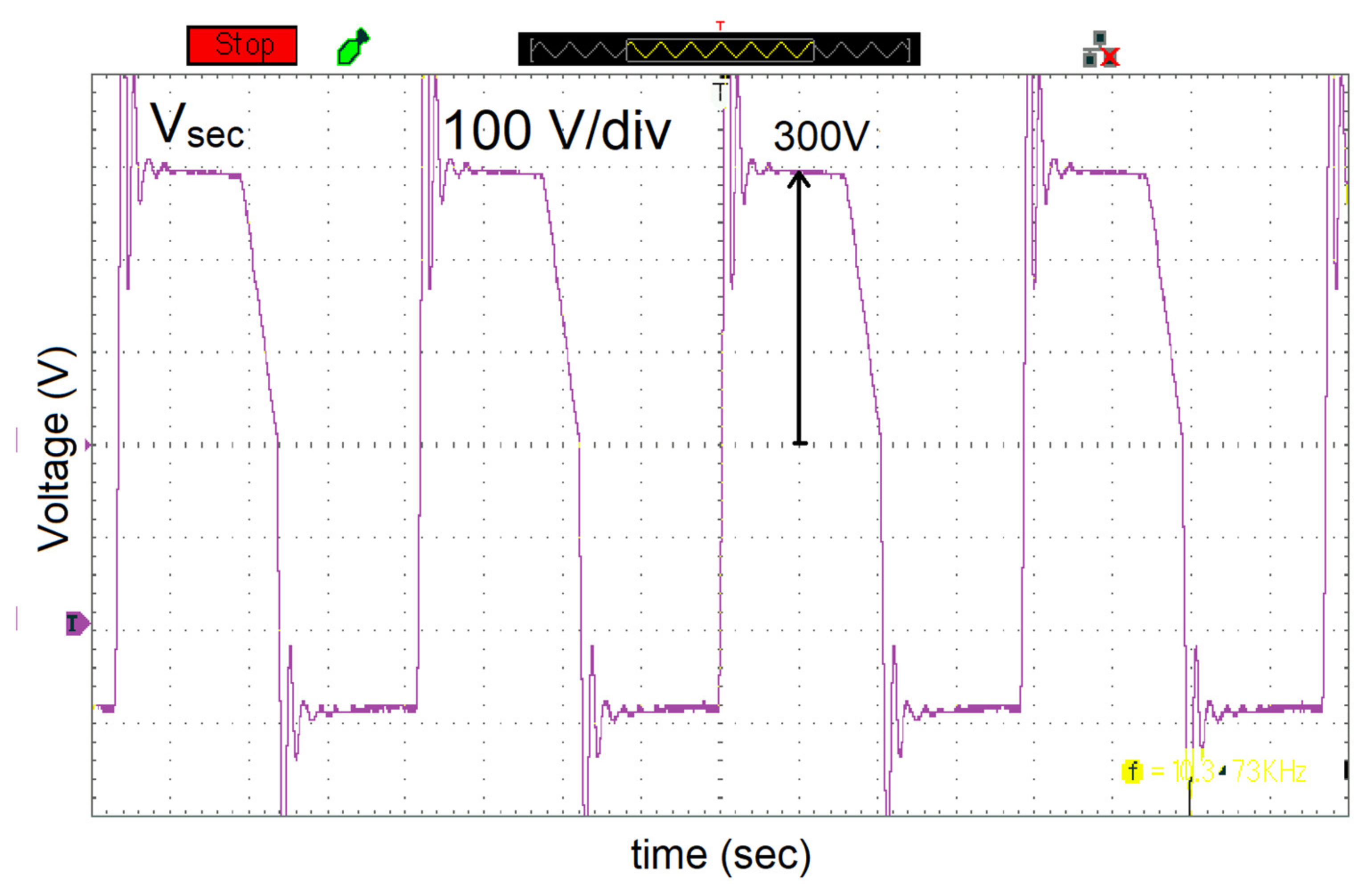
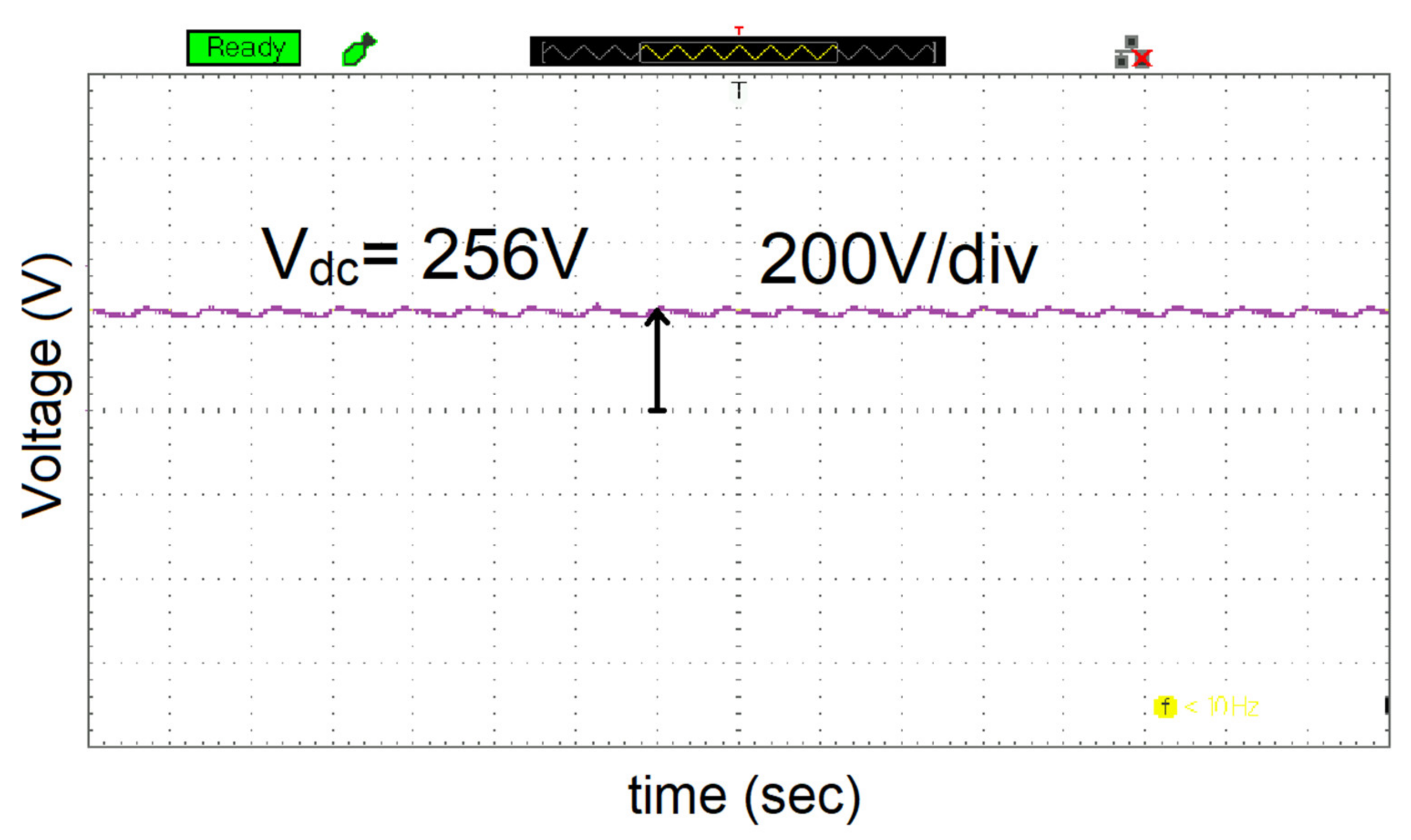
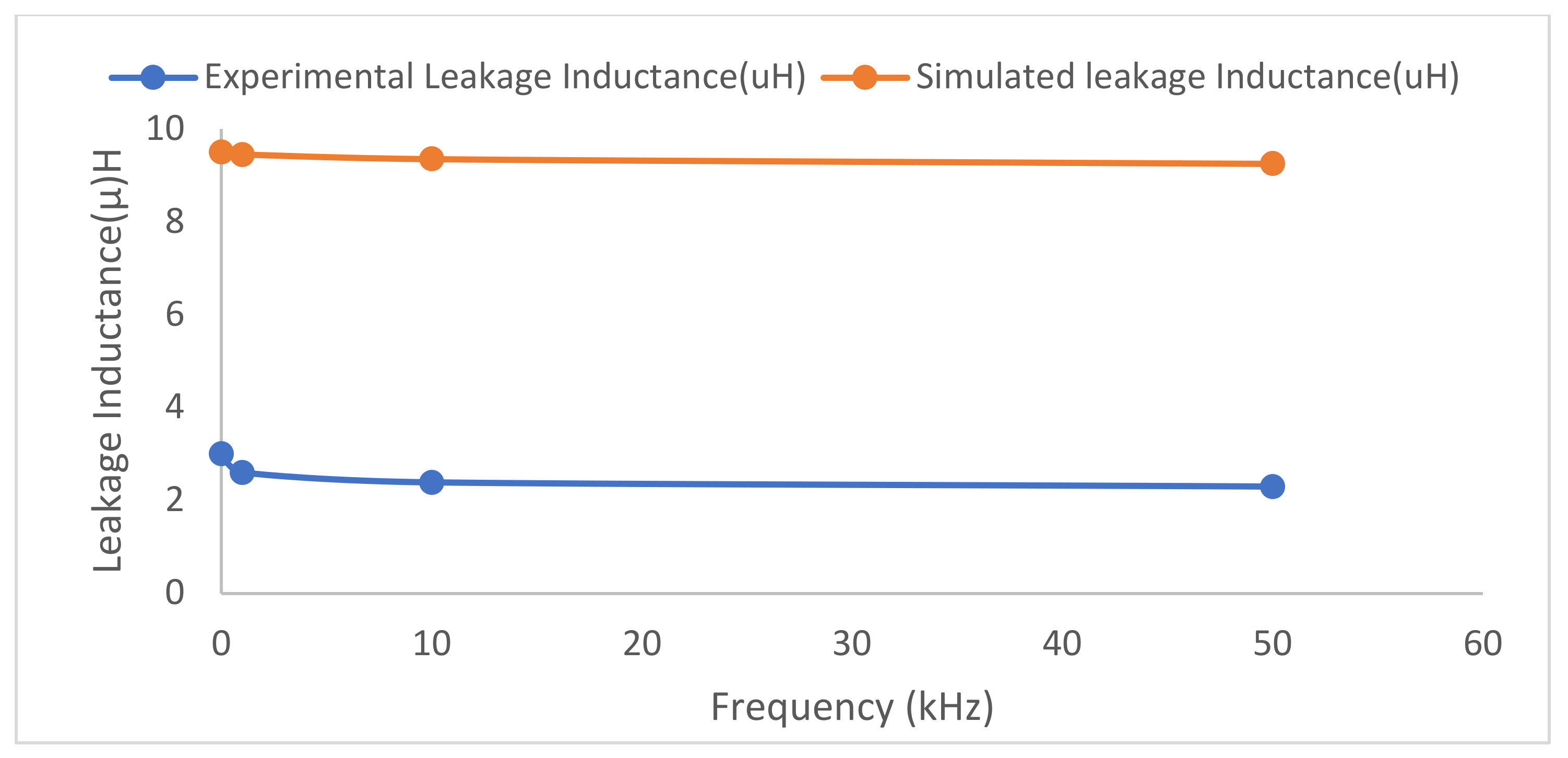
In order to verify the accuracy of the proposed frequency-dependent expressions in (1), a transformer consisting of Ferrite cores, one layer of solid wires consisting of 25 turns as the primary windings and four layers of solid round wire consisting of 600 turns as the secondary windings operating at 10 KHz were manufactured for the DAB converter and is illustrated in Figure 21. The high-frequency transformer was designed to be wound on the toroidal core using 10- and 18-gauge wire on the primary and secondary side, respectively. A ferrite core with a high permeability of 10,000 was selected to reduce winding complexity and the number of turns. Figure 22 and Figure 23 show the primary and secondary voltages of HFT while Figure 24 illustrate the output voltage of DAB converter. Similarly, leakage inductance was less when compared with core-type or shell-type transformers. Simulated and experimental leakage inductance of HFT was compared and shown in Figure 25.

8. Discussion

By FEM analysis proposed in this article, leakage inductance was obtained accurately, which maximized the power transfer in a DAB converter. The error between the analytical, simulated and experimental results were negligible. Furthermore, the following outcomes have been identified:
  • Instead of employing a conventional shell-type or core-type transformer, a high-frequency toroidal transformer was designed using FEM.
  • Since leakage inductance is a crucial component in limiting power transfer in DAB converters, it was analyzed as a function of frequency under various circumstances and minimal leakage inductance was attained.
  • A toroidal transformer with low leakage inductance was employed in the DAB converter and the simulated findings were confirmed using an experimental prototype.
  • Besides leakage inductance, parasitic capacitance could also be obtained using FEM and the behavior of the DAB converter could be studied.

9. Conclusions

In this paper, a single-phase toroidal transformer was discussed in the 2D ANSYS Maxwell platform. The aim was to study the effect of different design configurations on leakage inductance. For this purpose, different toroidal transformers were designed and various parameters, such as magnetic flux density, magnetic field strength and leakage inductance were discussed. The leakage inductance is a small fraction of the magnetizing inductance, but it can be significant in transformers with a high number of turns operating at high frequency. It was observed that minimizing the distance between the core and the winding caused leakage inductance to decrease. Another factor that affected the leakage inductance was the overlapping of windings. Leakage inductance obtained through simulation was similar to the analytical results, which validated the precision and reliability of the analysis. Since transformers are usually symmetrical, the results of 2D modeling in FEA were accurate and the time consumption was considerably less than multiple prototyping, manufacturing and measurement. More accuracy in analytical and simulated values can be achieved by decreasing the size of segments and increasing the number of meshes at the cost of increased computational time. High-frequency toroid used in DAB was further validated with the help of experimental prototypes.

Author Contributions

Conceptualization, H.A. and T.I.; methodology, I.U.K., software, H.A. and T.I.; validation, A.-S.M. and N.U.; resources, N.U. writing—original draft preparation, H.A. and T.I. writing—review and editing, N.U. and M.E.F.; funding acquisition N.U. and M.E.F. All authors have read and agreed to the published version of the manuscript.

Funding

This research was supported by Taif University Researchers Supporting Project number (TURSP-2020/144), Taif University, Taif, Saudi Arabia.

Institutional Review Board Statement

Not applicable.

Informed Consent Statement

Not applicable.

Data Availability Statement

Not applicable.

Conflicts of Interest

The authors declare no conflict of interest.

References

  1. Fouineau, A.; Raulet, M.A.; Lefebvre, B.; Burais, N.; Sixdenier, F. Semi-analytical methods for calculation of leakage inductance and frequency-dependent resistance of windings in transformers. IEEE Trans. Magn. 2018, 54, 1–10. [Google Scholar] [CrossRef]
  2. Zhao, X.; Liu, X.; Zhao, H.; Li, Y.; Liu, Y.; Yuan, D. Two-dimensional vector hysteresis modeling for soft magnetic composite materials considering anisotropic property. In Proceedings of the 2020 IEEE Industry Applications Society Annual Meeting, Detroit, MI, USA, 10–16 October 2020; pp. 1–6. [Google Scholar]
  3. Bahmani, M.A.; Thiringer, T.; Ortega, H. An accurate pseudo empirical model of winding loss calculation in HF foil and round conductors in switchmode magnetics. IEEE Trans. Power Electron. 2014, 29, 4231–4246. [Google Scholar] [CrossRef]
  4. De Leon, F.; Purushothaman, S.; Qaseer, L. Leakage inductance design of toroidal transformers by sector winding. IEEE Trans. Power Electron. 2014, 29, 473–480. [Google Scholar] [CrossRef]
  5. Naayagi, R.T.; Forsyth, A.; Shuttleworth, R. High-power bidirectional dc-dc converter for aerospace applications. IEEE Trans. Power Electron. 2012, 27, 4366–4379. [Google Scholar] [CrossRef]
  6. Alonso, A.; Sebastian, J.; Lamar, D.; Hernando, M.; Vazquez, A. An overall study of a dual active bridge for bidirectional dc/dc conversion. In Proceedings of the 2010 IEEE Energy Conversion Congress and Exposition, Atlanta, GA, USA, 12–16 September 2010; pp. 1129–1135. [Google Scholar]
  7. De Doncker, R.; Divan, D.; Kheraluwala, M. A three-phase soft switched high-power-density dc/dc converter for high-power applications. IEEE Trans. Ind. Appl. 1991, 27, 63–73. [Google Scholar] [CrossRef]
  8. Bahmani, M.A. Accurate Evaluation of Leakage Inductance in High-Frequency Transformers Using an Improved Frequency-Dependent Expression. IEEE Trans. Power Electron. 2015, 30, 5738–5746. [Google Scholar] [CrossRef]
  9. Bahmani, M.A. Design and Optimization of HF Transformers for High Power dc-dc Applications. Licentiate Thesis, Chalmers University of Technology, Gothenburg, Sweden, April 2014. [Google Scholar]
  10. Choi, J.-M.; Byen, B.-J.; Lee, Y.-J.; Han, D.-H.; Kho, H.-S.; Choe, G.-H. Design of leakage inductance in resonant DC-DC converter for electric vehicle charger. IEEE Trans. Magn. 2012, 48, 4417–4420. [Google Scholar] [CrossRef]
  11. Chen, K.; Kumar, N. Influence of isolation transformer leakage inductance on constant current output of class D series-parallel LCC-type resonant converter for light-emitting diode lighting application. IET Power Electron. 2014, 7, 1362–1373. [Google Scholar] [CrossRef]
  12. Muhammad, K.S.; Lu, D.-C. Magnetically isolated gate driver with leakage inductance immunity. IEEE Trans. Power Electron. 2014, 29, 1567–1572. [Google Scholar] [CrossRef]
  13. Stadler, A.; Albach, M. The influence of the winding layout on the core losses and the leakage inductance in high frequency transformers. IEEE Trans. Magn. 2006, 42, 735–738. [Google Scholar] [CrossRef]
  14. Zhang, K.; Chen, W.; Cao, X.; Pan, P.; Azeem, S.W.; Qiao, G.; Deng, F. Accurate calculation and sensitivity analysis of leakage inductance of high-frequency transformer with Litz wire winding. IEEE Trans. Power Electron. 2019, 35, 3951–3962. [Google Scholar] [CrossRef]
  15. Zheng, T.; Zhao, Y.J.; Ying, J.; Chen, P.L.; Zhang, F.F. Design and analysis on the turn-to-turn fault protection scheme for the control winding of a magnetically controlled shunt reactor. IEEE Trans. 2015, 30, 967–975. [Google Scholar] [CrossRef]
  16. Dowell, P.L. Effects of eddy currents in transformer windings. Proc. IEEE 1966, 113, 1387–1394. [Google Scholar] [CrossRef]
  17. Snelling, E.C. Soft Ferrites—Properties and Applications, 2nd ed.; Butterworth: London, UK, 1988. [Google Scholar]
  18. Kazimierczuk, M.K. High-Frequency Magnetic Components, 2nd ed.; Wiley: Chichester, UK, 2009. [Google Scholar]
  19. D’Antonio, M.; Chakraborty, S.; Khaligh, A. Planar transformer with asymmetric integrated leakage inductance using horizontal air gap. IEEE Trans. Power Electron. 2021, 36, 14014–14028. [Google Scholar] [CrossRef]
  20. Schlesinger, R.; Biela, J. Comparison of analytical models of transformer leakage inductance: Accuracy versus computational effort. IEEE Trans. Power Electron. 2020, 36, 146–156. [Google Scholar] [CrossRef]
  21. Ouyang, Z.; Thomsen, O.C.; Andersen, M.A.E. Optimal design and tradeoff analysis of planar transformer in high-power dc–dc converters. IEEE Trans. Ind. Electron. 2012, 59, 2800–2810. [Google Scholar] [CrossRef]
  22. Zhang, J.; Ouyang, Z.; Duffy, M.C.; Andersen, M.A.E.; Hurley, W.G. Leakage inductance calculation for planar transformers with a magnetic shunt. IEEE Tran. Ind. Appl. 2014, 50, 4107–4112. [Google Scholar] [CrossRef]
  23. Ostrenko, M.; Andriienko, B. Transformer impulse surges calculation by FEM coupled to the circuit. IEEE Trans. Magn. 2017, 53, 1–4. [Google Scholar] [CrossRef]
  24. Ouyang, Z. Calculation of leakage inductance for high frequency transformer. IEEE Trans. Power Electron. 2015, 30, 5769–5776. [Google Scholar] [CrossRef]
  25. Rothmund, D.; Guillod, T.; Bortis, D.; Kolar, J.W. 99.1% efficient 10 kV SiC-based medium-voltage ZVS bidirectional single-phase PFC AC/DC stage. IEEE J. Emerg. Sel. Top. Power Electron. 2018, 7, 779–797. [Google Scholar] [CrossRef]
  26. Bird, L.; Milligan, M.; Lew, D. Integrating Variable Renewable Energy: Challenges and Solutions; National Renewable Energy Laboratory: Golden, CO, USA, 2013. [Google Scholar]
  27. Michaud, A. Electr omagnetism According to Maxwell’s Initial Interpretation. J. Mod. Phys. 2019, 11, 16–80. [Google Scholar] [CrossRef]
  28. Ariani, H.A.; Iskender, I.; Karakaya, M. Performance analysis of a distribution transformer using ansys maxwell. Int. J. Tech. Phys. Probl. Eng. 2020, 12, 57–62. [Google Scholar]
  29. Del Vecchio, R.M.; Poulin, B.; Feghali, P.; Shah, D.; Ahuja, R. Transformer Design Principles: With Applications to Core-Form Power Transformers; CRC Press: Boca Raton, FL, USA, 2010. [Google Scholar]
  30. SimScale.com. What Is FEA|Finite Element Analysis. Available online: https://www.simscale.com/docs/content/simwiki/fea/whatisfea.html?utm_source=Blog&utm_medium=SimWiki%20Button&utm_campaign=SimWiki (accessed on 1 November 2018).
  31. Hamed, A.; Alyousef, A. Electrical Power Transformer; Blekinge Institute of Technology (BTH): Karlskrona, Sweden, 2016. [Google Scholar]
  32. Özüpak, Y. Performing structural design and modelling of transformer using ansys Maxwel. J. Brill. Eng. 2021, 2, 38–42. [Google Scholar] [CrossRef]
  33. Amirbande, M.; Vahedi, A. Calculation of leakage inductance in toroidal core transformer with non-interleaved windings. IEEE Trans. Ind. Electron. 2020, 48, 4215–4220. [Google Scholar] [CrossRef]
  34. Krismer, F.; Kolar, J.W. Efficiency-optimized high-current dual active bridge converter for automotive applications. IEEE Trans. Ind. Electron. 2012, 59, 2745–2760. [Google Scholar] [CrossRef]
  35. Karim, S.; Pamela, M. AESO Transformer Modelling Guide (PDF). Calgary: AESO—Alberta Electric System Operator (Prepared by Teshmont Consultants LP). 2018; p. 304. Available online: https://www.aeso.ca/assets/linkfiles/4040.002-Rev02-Transformer-Modelling-Guide.pdf (accessed on 2 August 2022).
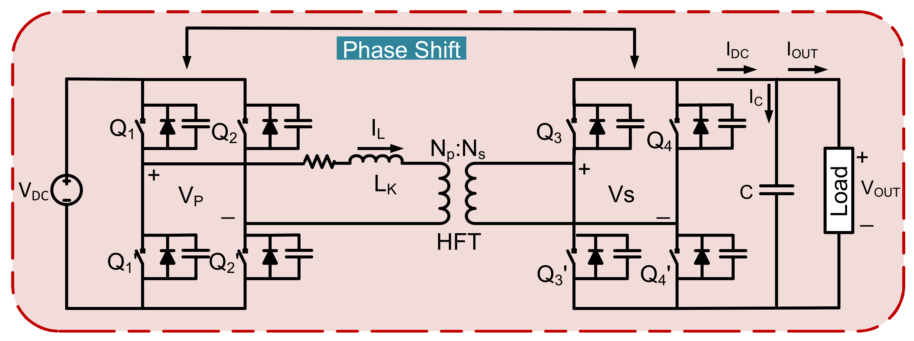
Figure 1. Schematic circuit diagram of a dual active bridge converter.
Energies 15 06176 g001
Figure 2. 2D Model of a toroidal transformer.
Energies 15 06176 g002
Figure 3. Core shapes: (a) Toroidal Core (b) Shell-Type Core.
Energies 15 06176 g003
Figure 4. Winding Design: (a) Toroidal Winding (b) Shell Type Winding.
Energies 15 06176 g004
Figure 5. Toroidal Core Dimensions Diagram.
Energies 15 06176 g005
Figure 6. Hysteresis curves of the ferrite core material.
Energies 15 06176 g006
Figure 7. Mesh of a Toroidal Transformer.
Energies 15 06176 g007
Figure 8. Input Voltage to a Transformer.
Energies 15 06176 g008
Figure 9. Magnetic field density on transformer core.
Energies 15 06176 g009
Figure 10. Magnetic Field Intensity Distribution (a) Toroidal transformer (b) shell-type transformer.
Energies 15 06176 g010
Figure 11. Magnetic flux.
Energies 15 06176 g011
Figure 12. MMF variation due to high frequency.
Energies 15 06176 g012
Figure 13. 2D toroidal transformer (NP = 5 & NS = 120).
Energies 15 06176 g013
Figure 14. Leakage inductance of toroidal transformer (Np = 5 & Ns = 120). (a) Primary winding (b) Secondary winding.
Energies 15 06176 g014
Figure 15. 2D toroidal transformer (NP = 15 & NS = 375).
Energies 15 06176 g015
Figure 16. Leakage Inductance of toroidal transformer (Np = 15 & Ns = 375). (a) Primary winding, (b) Secondary winding.
Energies 15 06176 g016
Figure 17. 2D Toroidal Transformer (NP = 24 & NS = 600).
Energies 15 06176 g017
Figure 18. Leakage inductance of toroidal transformer (Np = 24 & Ns = 600). (a) Primary winding, (b) Secondary winding.
Energies 15 06176 g018
Figure 19. Transformer voltages (a) Primary and secondary winding (b) Leakage inductance voltage and current.
Energies 15 06176 g019
Figure 20. DC output voltage of DAB converter.
Energies 15 06176 g020
Figure 21. Toroidal transformer tested in a dual active bridge converter.
Energies 15 06176 g021
Figure 22. Output voltage of H-bridge and input to high-frequency transformer.
Energies 15 06176 g022
Figure 23. Secondary voltage of high-frequency transformer.
Energies 15 06176 g023
Figure 24. Output voltage of a DAB converter.
Energies 15 06176 g024
Figure 25. Experimental and simulated comparison of Leakage Inductance.
Energies 15 06176 g025
Table 1. Toroidal Core Dimensions and Properties.
Dimensions and CharacteristicsValues
Outer diameterOD80 mm
Inner diameterID50 mm
Core heighth20 mm
Effective lengthle197 mm
Effective cross-section areaAe295 mm2
Table 2. Design Summary of Transformer Design.
ParameterFormulaValue
Primary SidePower rating (VA)(Known)1 KVA
Primary voltage (VP)(Known)24 V
Current (IP)(8)41.66 A
Wire Gauge(standard table)10 SWG
Secondary SideSecondary Voltage (VS)(Known)600 V
Current (IS)(8)1.66 A
Wire Gauge(standard table)18 SWG
Table 3. Electrical Information for Toroidal Transformer Design.
Design ParameterValues
Rating power1 kVA
High voltage (Secondary Side)600 V
Low voltage (Primary Side)24 V
Frequency10 kHz
Core materialFerrite N41
Table 4. Design parameters for different cases of toroidal transformer.
Case: 1Case: 2Case: 3
Frequency50 k20 k10 k
BMAX0.1 Tesla0.1 Tesla0.1 Tesla
Primary Turns51524
Secondary Turns120375600
Area295 mm2295 mm2295 mm2
LK (Analytical)3 µH9 µH9.65 µH
LK (Simulated)1.88 µH8.5 µH9.5 µH
Table 5. Parameters for the proposed scheme.
Circuit ParametersValues
Input VoltageVin12 V (DC)
Output Voltage (DAB)Vout294 V (DC)
Turns RatioNP:NS1:25
Switching frequencyfS(VSI)10 kHz
Switching frequencyfS(DAB)10 KHz
DC capacitanceC10 mF
Nominal Output PowerPO1 KW
Table 6. Comparison between simulated and experimental values.
ParametersSimulated ValuesExperimental Values
Primary Voltage12 V12 V
Secondary Voltage270 V275 V
DAB output Voltage286.5 V256 V
Publisher’s Note: MDPI stays neutral with regard to jurisdictional claims in published maps and institutional affiliations.