1. Introduction
Optical encoders are the most commonly used measurement devices in industrial applications because of their high accuracy, resolution, good repeatability and relatively low price. They convert angular or linear displacement into electrical signals which indicate the position and direction of motion. After further signal processing [
1,
2,
3] by a numerical control device, this information can be used to determine the speed and control of moving units of various technological machines and other equipment.
Discussed and developed in our previous paper [
4], the experimental reading head for a Moiré effect-based optical linear encoder is used for the experimental analysis of the influence of different reading head designs on an encoder’s performance under various mounting inaccuracies and external mechanical vibrations.
Linear encoders are used in a wide range of applications. Not only can they precisely measure the displacement of the reading head (incremental encoders), but they can also determine its absolute position [
5,
6,
7], which is very advantageous. Regarding mechanical construction, linear encoders may be an enclosed or open type. Enclosed-type linear encoders based on the Moiré fringe scanning method have an aluminum extrusion that encloses and protects the measuring scale and reading head from dust, dirt, chips or splashing coolant. Such measuring systems, together with a digital readout, are used in various manually controlled machine tools [
8], and their more accurate versions are used in numerically controlled CNC machines [
9]. For typical manual control milling machines or lathes, display steps of 10 µm or 5 µm and an accuracy of ±10 µm per meter are sufficient. For more precise measurements and inspection tasks, grinding or jig boring machines, display steps should reach 1 µm, and accuracies of ±5 µm or ±3 µm are desirable. In modern CNC machines, these requirements should be even higher. Due to the sealed construction and the self-guided scanning carriage moving along the measuring scale surface, the accuracy of an encoder is limited by friction and hysteresis effects.
Open-type linear encoders consist of a measuring scale attached directly onto a support of the application and the scanning head. The working principle of such a configuration system is based on non-contact reflective scanning that operates without any mechanical contact. They are used in machines that require very high accuracy, such as PCB assembly machines, high-accuracy machine tools; coordinate measuring machines (CMMs); and other precise measuring devices, positioning stages, etc. [
10]. With an implemented interferodiffractive grating scanning technique, new open-type laser encoders are capable of measuring not only linear displacement to an accuracy of less than 1 µm, but also detecting and evaluating multi-degrees-of-freedom linear motion errors [
11,
12,
13,
14,
15].
It is clear that different applications require different linear encoders with a specific accuracy and resolution. Various technological processes performed in machines create particular environmental conditions in which a linear encoder can operate. Changes in temperature due to heat generation during the metal cutting process and usage of coolants, mechanical vibrations, various mounting inaccuracies, deformations and translations are typical circumstances that inevitably influence an encoder’s performance [
16].
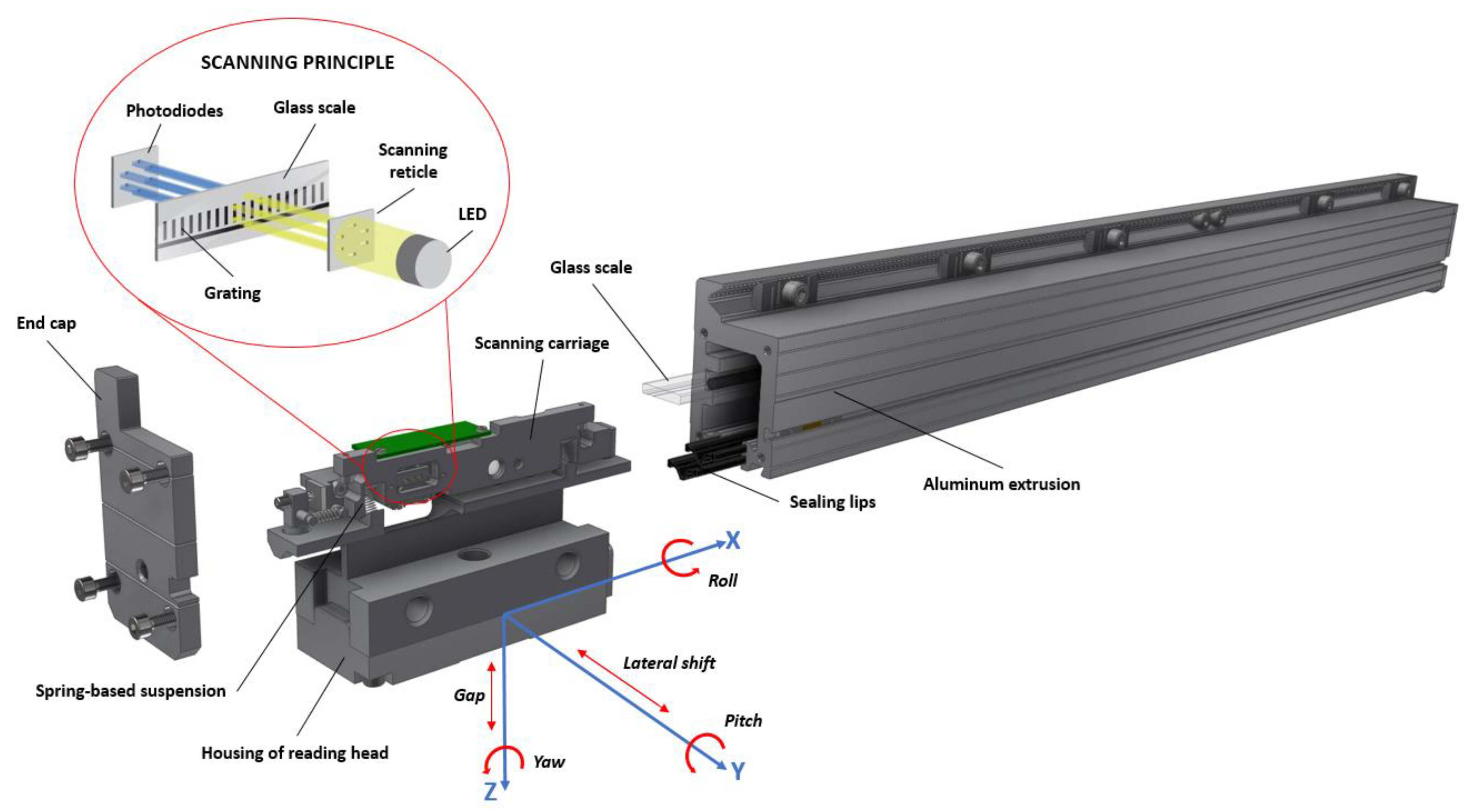
This paper focusses on enclosed-type optical encoders based on the Moiré fringe scanning method [
17,
18,
19], which can measure only single-axial linear displacement. Their construction and scanning principle scheme is shown in
Figure 1.
Such encoders are reliable and have a low cost, so they are usually the first choice for ordinary industrial applications. The accuracy of the measuring process and the formation of good quality electrical signals depend on miscellaneous factors. These factors include undesirable variations in gap [
20,
21] and tilt [
22,
23] between the optical components, optical noise fluctuations due to measuring scale imperfections, variations in light intensity and the sensitivity of used photodetectors and other effects that lead to a poor contrast in Moiré fringe and electrical signal distortion. The majority of these errors can be drastically minimized by correctly designed reading heads. Mechanical constructions and engineering solutions play an important role. A flexible spring-based suspension connecting the scanning carriage and the reading head housing must ensure constant angle position and a gap between the scanning reticle and the measuring scale. The construction must not only be flexible, absorbing all deviations of an application guideway, but also limit any additional scanning carriage motion along the measuring axis. This can be achieved by using rigid parts such as stainless steel pins and hardened plates, which are kept in contact during bidirectional motion of the reading head. The stability of this contact is especially important as high acceleration, friction between protecting sealing lips and the reading head or mechanical vibration can cause a temporary loss of this contact. Even a small additional motion of the scanning carriage along the measuring scale surface leads to direct measuring errors. Hysteresis and repeatability errors are also directly related.
Another typical problem in practice is correct linear encoder mounting. Typically, an aluminum extrusion of the enclosed encoder is attached to a rigid support of an application, whereas the reading head is fixed on the moving unit. Frequently, the reading head is supported by an additional steel or aluminum plate. The final alignment of such an assembly can introduce various deviations from the original position of the reading head. When considering the position between the measuring scale and the reading head in the construction of an encoder, there are five possible types of inaccuracies, corresponding to the degrees of freedom: two linear translations along the non-measurable Y (lateral shift) and Z (gap) axes, and three rotations around the X (roll), Y (pitch) and Z (yaw) axes. All these possible mounting errors are marked in
Figure 1. Each of these deviations, or typically a combination, causes some kind of translation or small deformation. For example, even a small pitch (rotation around the Y axis) initiates a relatively big translation of the contact point if the rigid elements of the so-called “contact pair” are located at the tip of the reading head. Furthermore, if the reading head of an encoder is mounted with an increased gap (linear motion along the Z axis), suspension springs become less suppressed, and the scanning carriage is pushed towards the glass scale with a smaller force.
The performance of an optical linear encoder is described by the following main parameters: accuracy and repeatability. It is clear that in real operating conditions, these parameters are changed and no longer meet the manufacturer’s declared values. In order to understand the ongoing processes and design of more reliable encoders, a more detailed knowledge and experimental analysis are necessary. In this paper, a brief review of the main parameters is presented, and the experimental analysis of an encoder’s performance under different mounting and dynamic conditions is accomplished. The experimental reading head developed in previous work [
4] is used to analyze the behavior of different mechanical reading head designs recently used in real encoders.
2. Performance of Optical Encoder
Optical encoders can be connected to a digital read-out device for a visual representation of the displacement value. Furthermore, its feedback position information can be sent to a microcontroller in order to create a closed-loop control system. Either way, encoder parameters such as resolution, accuracy and repeatability are essential for a correct performance.
2.1. Resolution
Resolution is the smallest positional increment that can be measured. In other words, it is the smallest distance an encoder is able to measure. The higher the resolution, the more precise the positioning of the moving unit that can be reached. This means a more fluent motion can be generated by a closed-loop control system. The resolution of an optical linear encoder is based on the measuring scale grating. The number of transparent and opaque lines defines the smallest measurable distance. The most frequently used grating pitch in a Moiré effect-based encoder is 20 µm. Practically, it is impossible to increase the resolution of an already manufactured encoder, but there are other methods to do this. Most incremental linear encoders generate two quadrature output signals, A and B. Since these signals are phase-shifted by 90 degrees, the direction of displacement can also be detected. With such quadrature output, three types of decoding, i.e., X1, X2 and X4, can be used to increase the resolution. The main idea of the decoding process involves counting different falling and rising edges of output signals [
24]. Thus, an optical linear encoder with a 20 µm grating pitch could reach a resolution of 5 µm after its electrical signals have been decoded by an external microcontroller. This can be integrated into the control unit of the machine tool or digital readout device.
For an encoder’s output signal to reach a higher resolution, a process called interpolation is used. However, electrical signals from an encoder must have a sinusoidal shape. Each period of the sinusoidal signal can be represented by many finer possible positions. There are many different methods for sinusoidal signal interpolation, such as tracking-loop, direct dual-sample-rate and direct high-sample-rate interpolators [
25]. Modern technologies allow us to sample sinusoidal signals higher than the Nyquist rate, with a high resolution even when the frequency of an encoder’s output signal is very high. Field-programmable arrays (FPGAs) together with analog electronics and noise filtering systems are used as practical solutions [
26].
To reach the correct interpolation process, the quality of an encoder’s signal is very important. Sinusoidal signal gain versus speed, offset and phase errors between sine and cosine signals, and sampling errors are limiting factors that limit accuracy when interpolating an encoder’s data [
27]. Therefore, an encoder’s ability to generate good and undistorted signals is crucial in order to reach a high resolution.
2.2. Accuracy
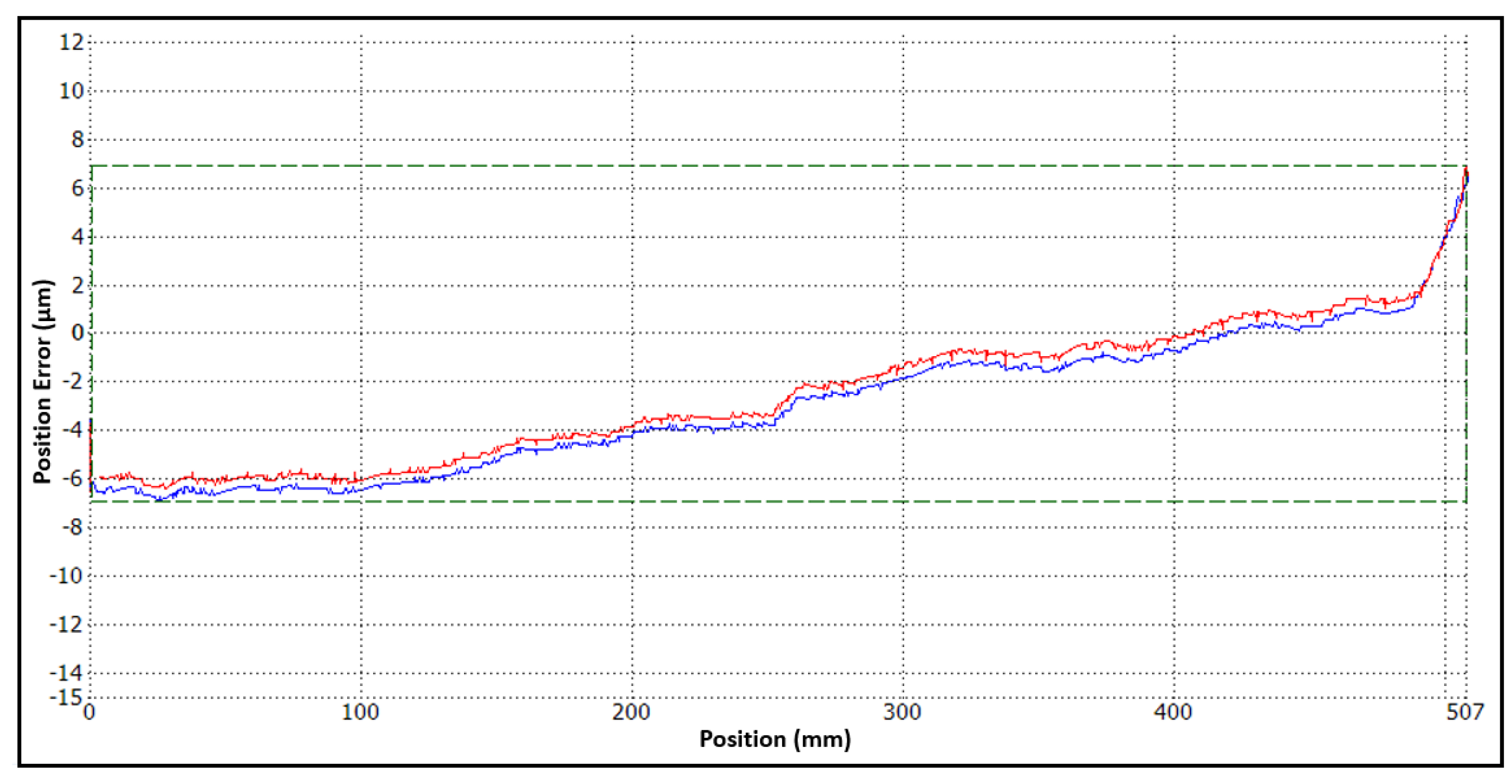
Accuracy and resolution are usually independent design parameters. Accuracy is described as the difference between a the true displacement value and a value that is determined by an encoder’s reading head. All manufactured encoders are tested and have a certain graph of error, as shown in
Figure 2.
This graph represents the difference between a tested encoder’s displacement measurement readings and readings of a reference measurement, usually given by a laser interferometer. These differences are accepted as position errors, and the combination of these errors over all measuring lengths is considered as an encoder’s accuracy.
Miscellaneous mechanical considerations make up the largest part of errors, which affects an encoder’s accuracy. For linear encoders, the quality of the measuring scale has a major impact. The precision of the geometry and the pitch of opaque and transparent bars dictate a principal accuracy that the whole displacement measuring system should reach. When the scale is attached to the aluminum extrusion by a thin adhesive layer, any imperfections in the mounting surface flatness are directly transferred to the glass scale, and a degree of error is unavoidable during the measuring process. In designing a reading head, various friction effects emerging during the movement of the scanning carriage along the glass scale surface will also induce errors. This causes a decrease in accuracy. In
Figure 2, these factors are represented as a slope and linearity faults in the graph lines. They define accumulative and non-accumulative positional errors over the whole measurement length of the encoder. The higher frequency harmonics are related to distortion of the electrical signals that occur due to the optical scanning, diffraction and interpolation processes. The total accuracy of an encoder is usually described as a plus/minus value of error per meter (±µm/m).
The produced device calibration process is carried out in well-defined mounting and environmental conditions where temperature is strictly maintained at 20 degrees Celsius and mechanical vibrations are highly minimized such that the received results describe the accuracy of the separated encoder. In reality, displacement measuring systems are integrated into various mechatronic systems that operate under different environmental conditions that may affect the accuracy of a linear encoder.
2.3. Repeatability
An encoder’s ability to record the same value every time when the reading head reaches the same position is called repeatability. It is often referred to as precision. It is usually a small quantity specified as ± resolution and is several times better than the accuracy of an encoder. In certain technological machines such as in pick-and-place applications, repeatability is even more important than accuracy.
However, parameters such as repeatability must be summed up correctly and be considered when regarding equipment in which a linear encoder is installed. If the machine demonstrates high repeatability, the mismatch between measured and reference values can be compensated for, so an encoder with high repeatability is required. On the other hand, an application with poor repeatability due to a backlash in mechanical gears, friction effects or hysteresis cannot be upgraded even by an encoder with absolutely perfect repeatability.
As shown in
Figure 2, the error graph combines two data lines of calibration: when the reading head is translated along the measuring scale (red line), and when it returns back to its start position (blue line). The differences between the values of those lines at certain points of an encoder’s measuring length can be considered as bi-directional positioning repeatability and also describe the error of hysteresis.
3. The Experimental Setup
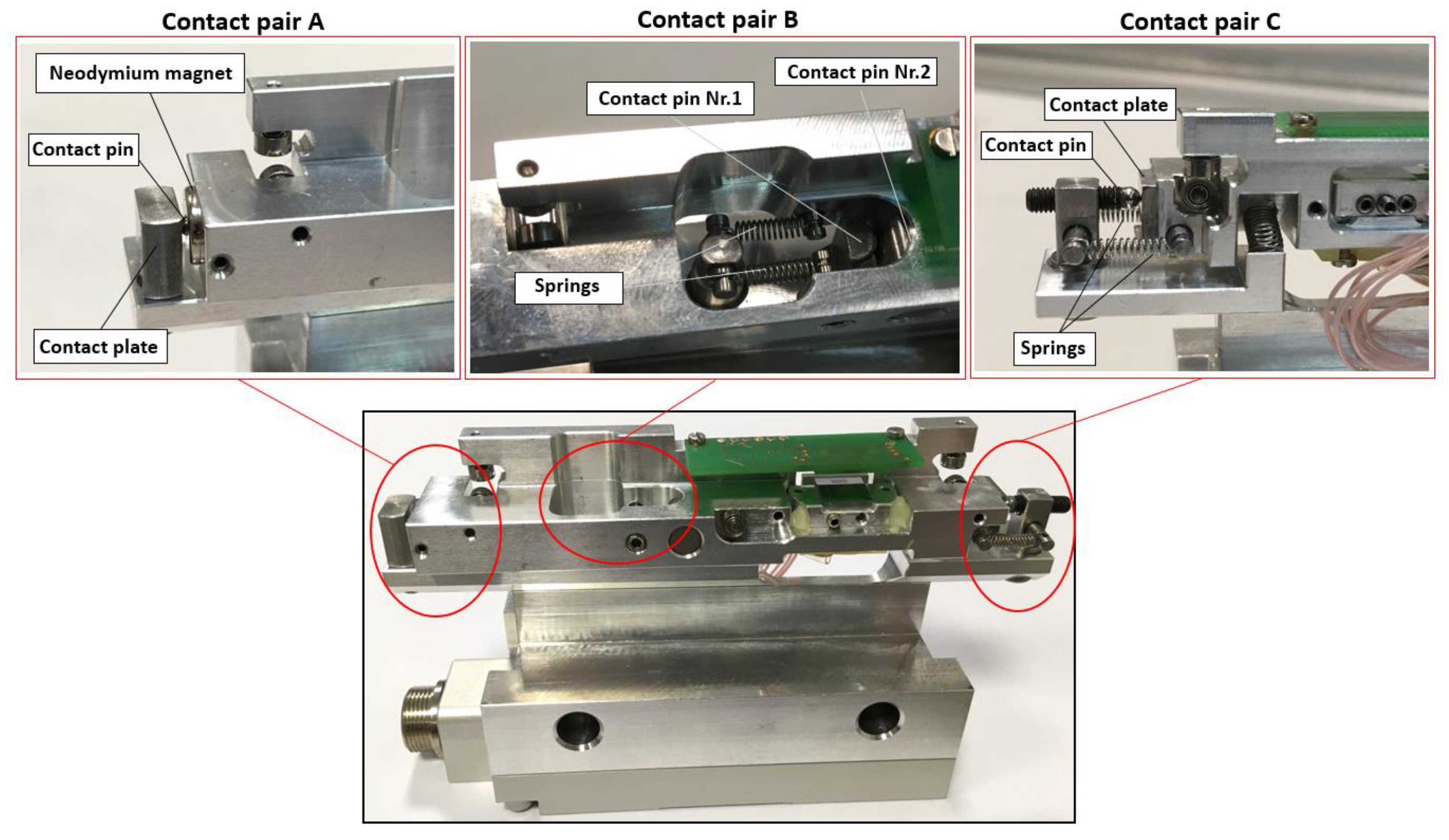
The main idea of this experimental research was to test different mechanical designs of a linear encoder’s reading head and analyze its performance under different mounting and dynamic conditions. For this purpose, the developed experimental reading head [
4] was used. In order to maintain the same conditions for every test, all three mechanical designs were integrated into a single reading head with the possibility of easily changing necessary parts and rearranging the construction. Each construction ensures close contact between the cursor and the housing of the reading head. This contact (called “contact pair”) is between rigid parts such as stainless steel plates and hardened pins to ensure appropriate motion. This is because the reading head must have a flexible spring-based suspension and a rigid one contact point. Even temporal contact separation due to high inertia forces or any kind of translation or deformation of the contact pair can generate transient or regular lack of measurements. The manufactured experimental reading head and detailed views of each design are shown in
Figure 3.
The overall investigation is divided into two main parts: performance analysis under different mounting conditions and an investigation of the encoder’s dynamic behavior under external mechanical vibrations. Both of these tests require their own experimental setups and detailed explanations.
3.1. Performance Analysis under Different Mounting Conditions
The encoder’s accuracy and repeatability when the reading head is mounted with various inaccuracies were analyzed by using JSC “Precizika Metrology” technological equipment—a linear comparator. A mechanism more than three meters long was used to compare an encoder’s readout with a precise compensated measuring scale.
The experimental reading head was mounted onto the linear comparator in six different ways:
- (1)
An original position with a minimal mounting deviation;
- (2)
Yaw deviation (0.5 degree);
- (3)
Pitch deviation (0.5 degree);
- (4)
Roll deviation (1 degree);
- (5)
A lateral shift (1 mm);
- (6)
A minimized gap between the reading head housing and the aluminum extrusion (from an original gap of 1.5 mm to 0.5 mm).
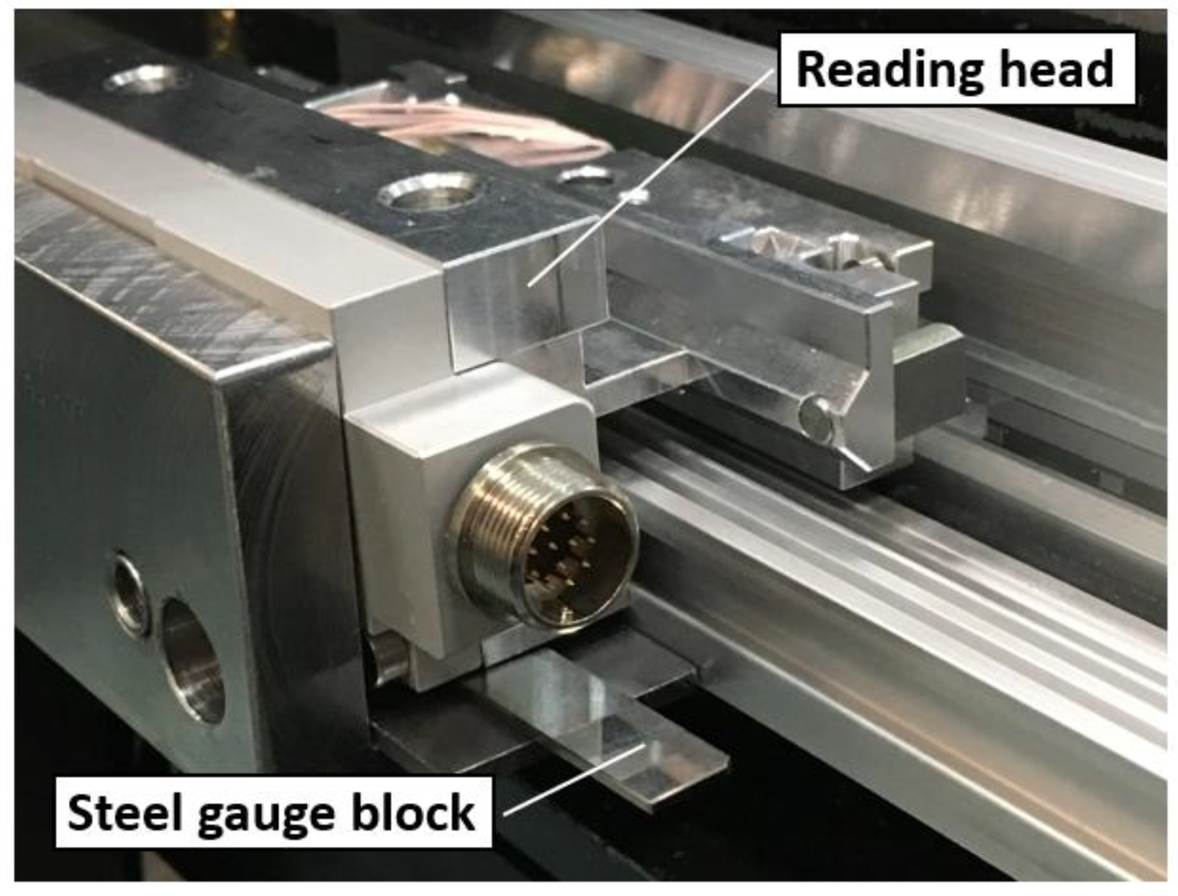
All inaccuracies were achieved by using steel gauge blocs of different thickness and putting them under mounting surfaces of the reading head, as shown in
Figure 4.
Five different measurements for each mechanical design, each mounting type and measuring direction were conducted. The main parameters were evaluated according to the standard ISO 230-2. The bi-directional systematic positioning error value of the performed experimental measurements was accepted as the accuracy parameter of the tested encoder (± µm/m). The maximal bi-directional positioning repeatability value (of all certain measured positions) was considered as the repeatability. The same fragment of the aluminum extrusion with a 1 m long glass scale was used in all measurements to reduce the uncertainty of the experiment.
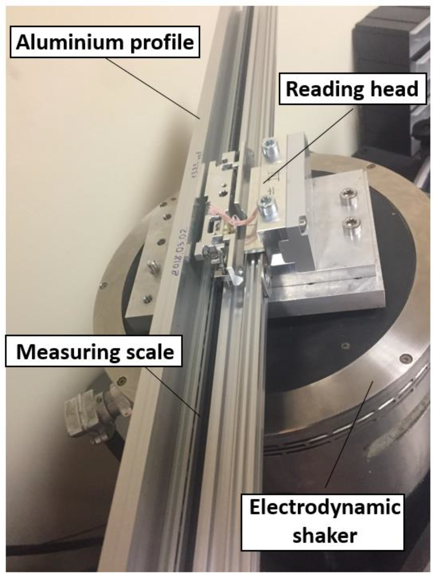
3.2. Investigation of the Dynamic Behavior
The experimental analysis of the encoder’s behavior under mechanical vibration was based on the methodology published by I. Alejandre et al [
28]. The aluminum extrusion along with the glass scale and experimental reading head were mounted onto the electrodynamic shaker in a fixed position, as shown in
Figure 5.
Even a small scanning carriage oscillation along the measuring scale generates electrical signals because of the relative motion between the two gratings. If this motion is smaller than a period of the measuring scale grating (period of the testing encoder is 20 µm), its generated signals can be represented as a circumference arc of the Lissajous curve. The full Lissajous curve corresponds to the motion that is equal to the whole period.
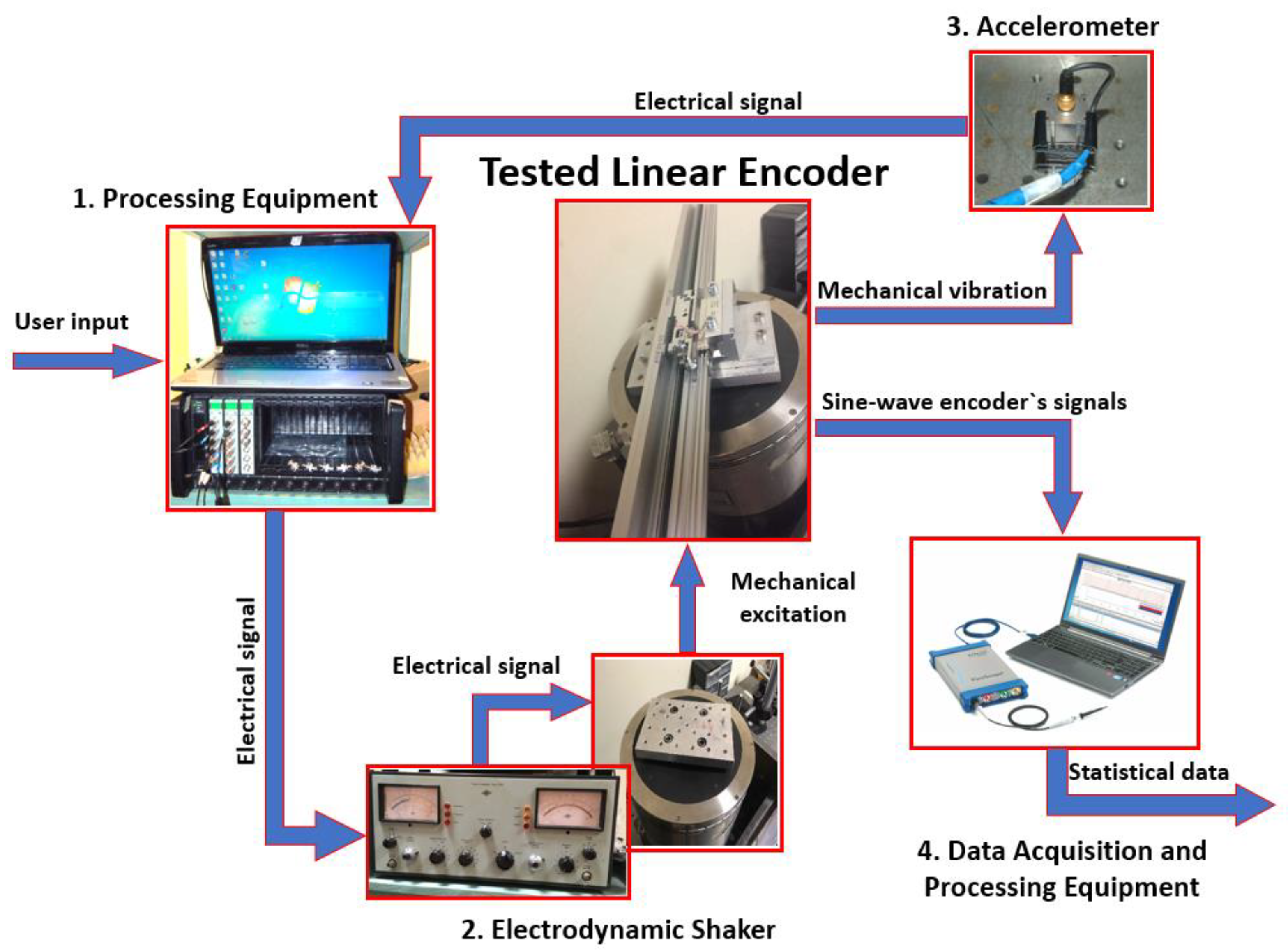
The tested encoder’s error under vibration was determined from the collected electrical signal data by analyzing the representative arc size. Electrical 1V peak-to-peak signals (Sin and Cos) from the developed encoder’s reading head were recorded using a digital oscilloscope and analyzed by using the software “MATLAB”. According to the recommendations of EN 60068-2-6, the analyzed range of sine waveform excitation frequencies is from 50 Hz to 2000 Hz. Discrete mechanical excitations generated by the electrodynamic shaker, with a frequency step of 50 Hz and amplitude of 40 m/s2, were used in this experiment. For more detailed information, a three-axis accelerometer was attached on the scanning carriage to senses its response.
The equipment used for the experimental research, shown In
Figure 6, is as follows:
- (1)
Processing equipment: “B&K” (Brüel & Kjaer) 3660-163 D LAN-XI data acquisition hardware with a generator; I/O module LAN-XI Type 3160.
- (2)
Electrodynamic shaker: a “B&K” 4812 general purpose head; a 4805 permanent magnet body; and a 2707 power amplifier.
- (3)
Accelerometer: a “B&K” 4506 triaxle piezoelectric accelerometer.
- (4)
Data acquisition and processing equipment: a digital oscilloscope “PicoScope 3000” and a “DELL” notebook with an appropriate software.
4. Results and Discussion
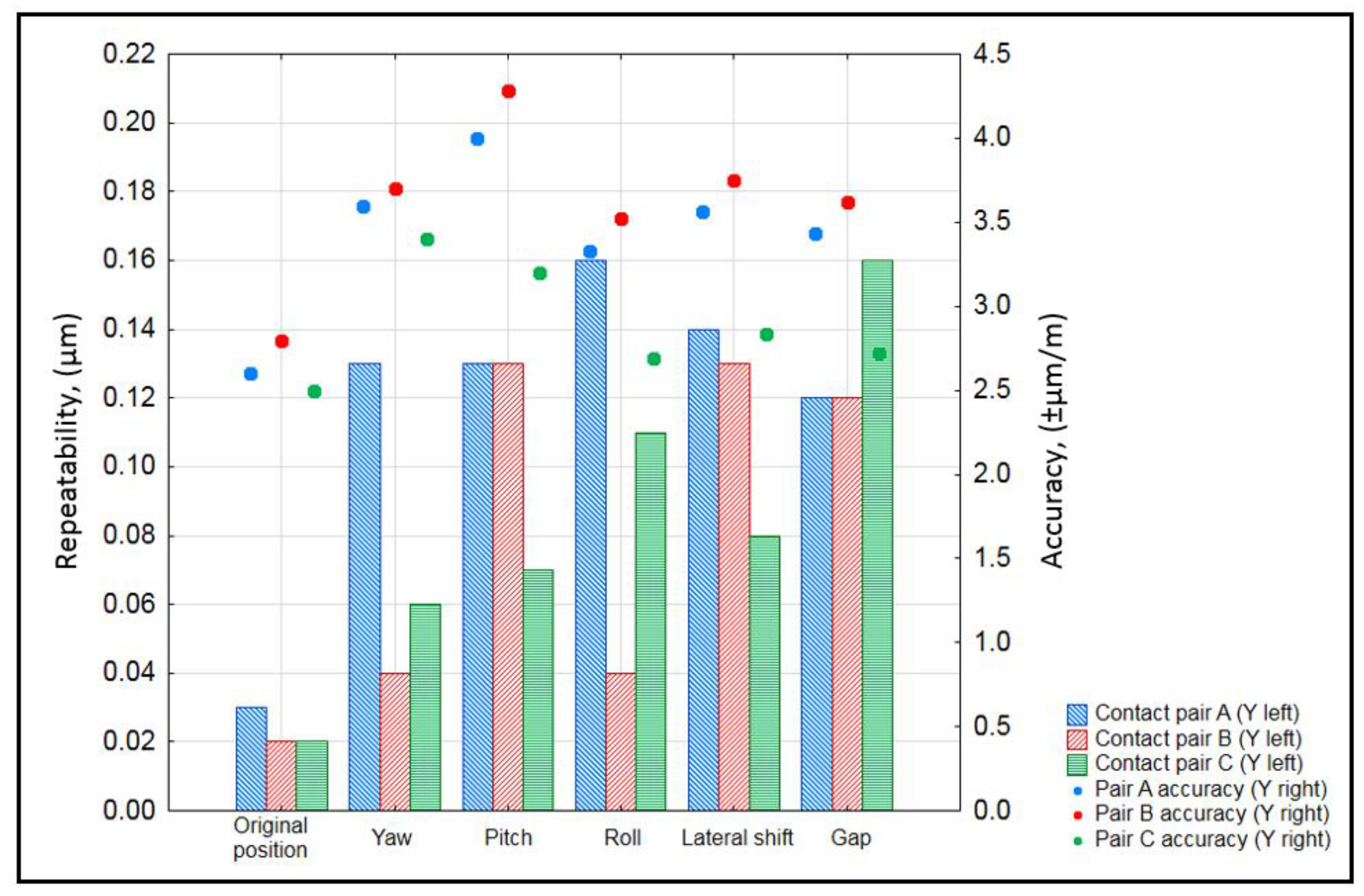
The analyzed and summarized data of the encoder’s repeatability and accuracy when the reading head was mounted with a different type of inaccuracy are plotted in
Figure 7.
All three mechanical designs of the reading head performed similarly in the original position. The repeatability was around 20–30 nanometers, and the accuracy of the reading head consisting of contact pair A contact pair B and contact pair C was ±2.5 µm/m, ±2.3 µm/m and ±2 µm/m, respectively. However, when the encoder’s reading head was mounted with various deviations, the behavior of each construction started to differ.
The reading head design with contact pair A had an advantage as it contained a neodymium magnet, and its assembly was much easier and faster than that of the other two. There were no springs, so the scanning carriage and the housing were kept in contact by the magnetic field force. The results show, however, that the reading head with this type of mechanical design was noticeably more sensitive to inaccuracies than the other constructions, especially when the reading head was rotated around the Z (yaw) and X (roll) axes. The maximum repeatability value reached about 160 nm, and the accuracy varied from ±2.5 µm/m (original position) to ±4 µm/m (0.5 degree pitch).
The design consisting of contact pair B was less sensitive to yaw and pitch deviations, because it was the only construction in which the contact pair was placed in the middle of the reading head and had contact between the two pins. This showed high values of repeatability when the reading head was mounted with a 0.5 degree pitch, a 1 mm lateral shift and a decreased air gap of as much as 0.5 mm. The accuracy values of all tested mounting deviation types were the biggest and reached ±4.28 µm/m (0.5 degree pitch).
The reading head with contact pair C had the highest repeatability value when the air gap between the reading head and aluminum extrusion (gap) was decreased, and it showed the best performance when the reading head was rotated around the Y axis (pitch) or was laterally shifted by 1 mm. The linear displacement measuring system with this contact pair was the most resistant to all mounting inaccuracies being investigated. The accuracy varied from ±2 µm/m (original mounting position) to ±3.4 µm/m (yaw).
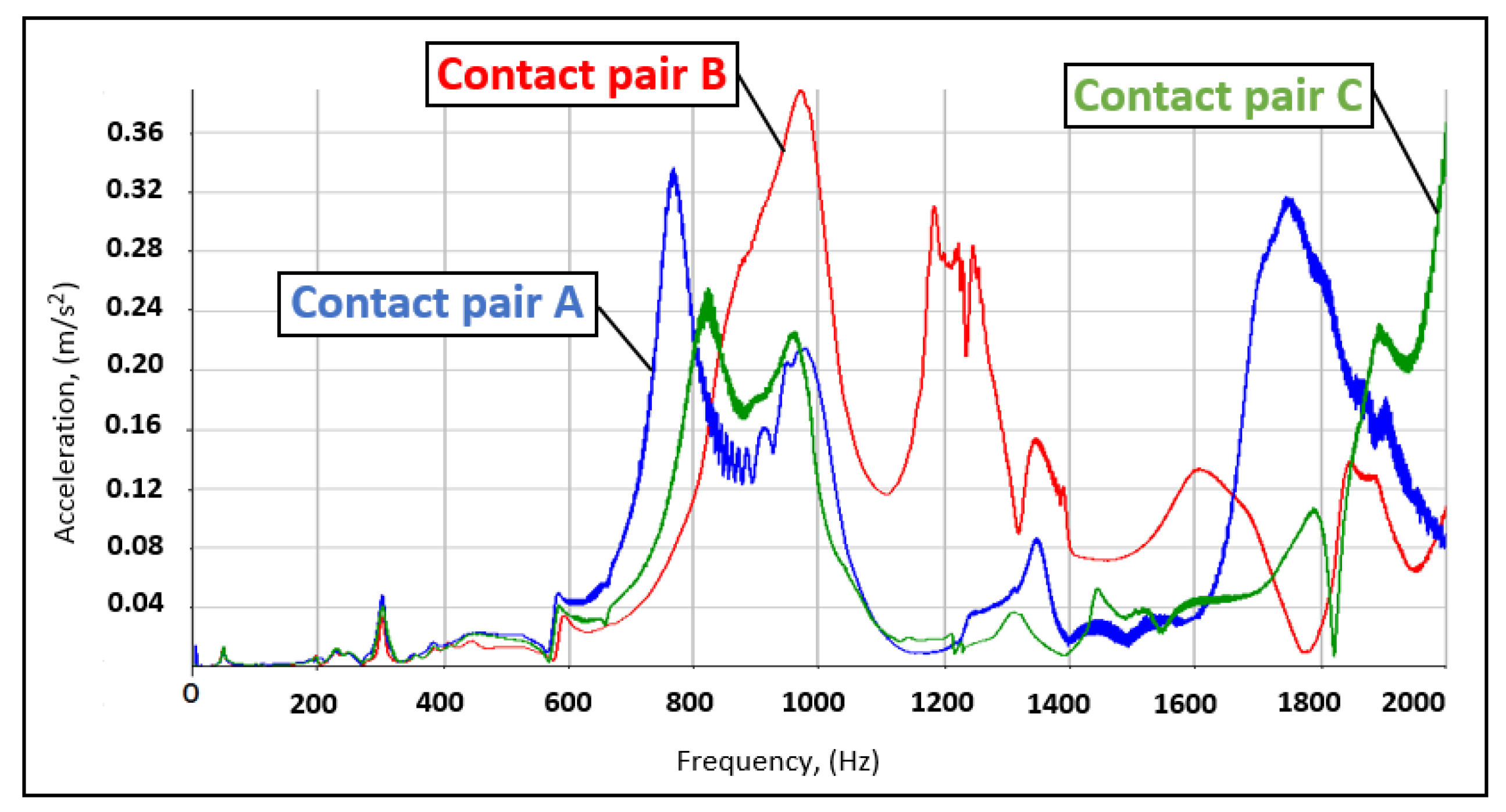
The data collected by the accelerometer represent the dynamic response of the reading head to an external mechanical excitation. Three graphs of each of the contact pair are plotted in one, as shown in
Figure 8.
Figure 8 visualizes the reading head oscillations along the measuring scale (X axis). Since each design of the contact pair is located in different places of the reading head and consists of different elements, the stiffness and other mechanical parameters are not the same. The peaks in this graph present the main resonant frequencies that are harmful and can cause measurement errors or even damage the encoder. For all three mechanical designs, the frequency range between 600 and 1400 Hz was found to be precarious. In addition, a certain number of additional peaks are noticeable in each graph.
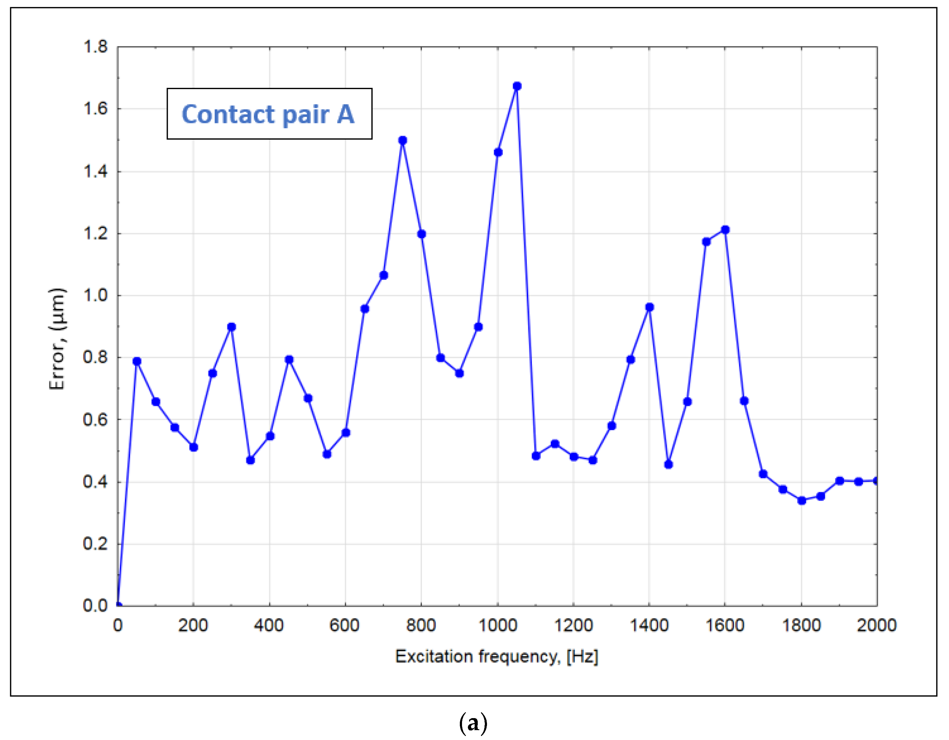
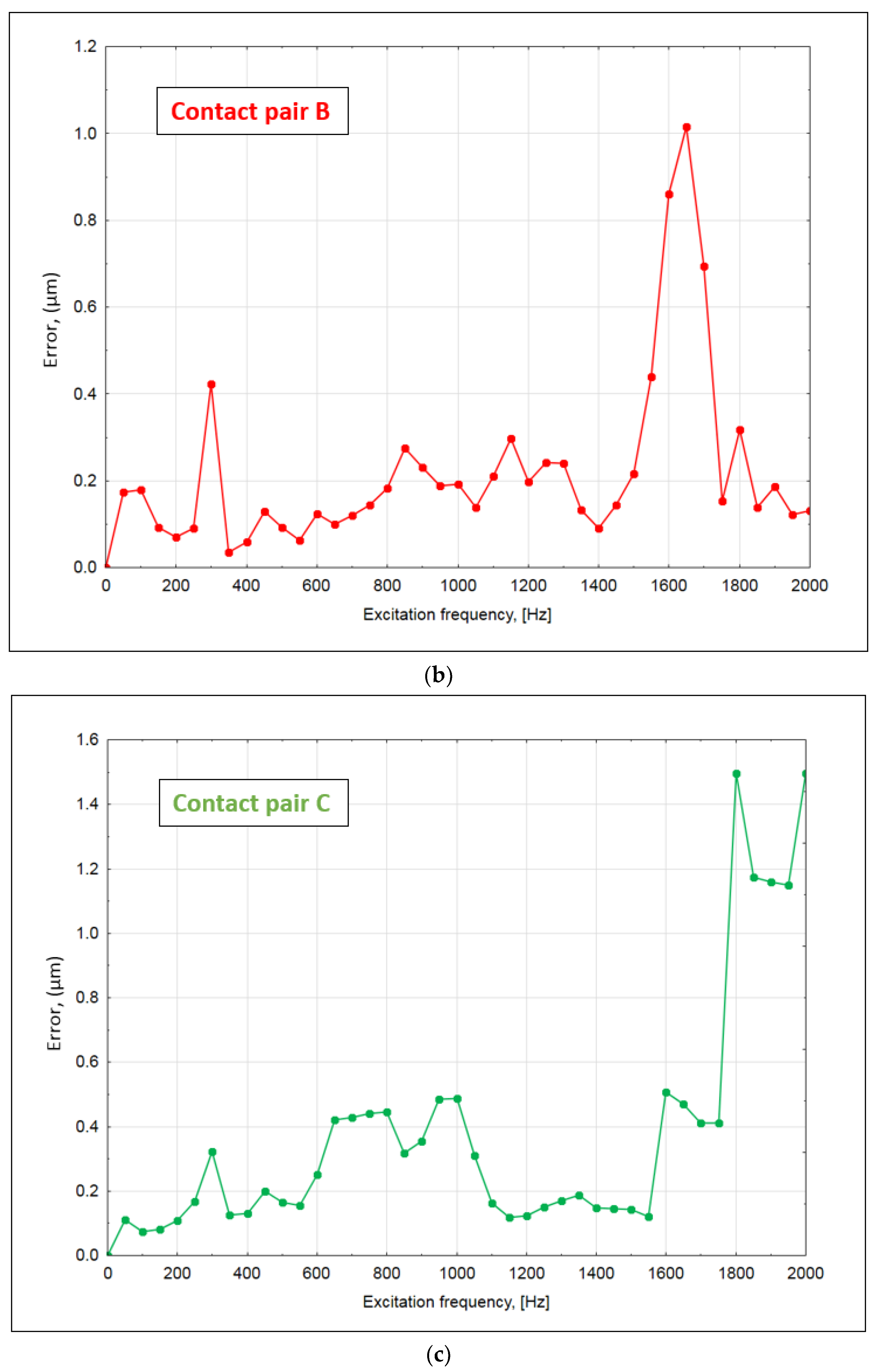
The encoder’s errors generated by external mechanical vibrations are shown in
Figure 9.
Although the electrodynamic shaker excitation amplitudes were not very high, they were sufficient to distinguish the dynamic effects that have a direct impact on the quality of the displacement measurement. The reading head with contact pair A had several clear peaks distributed over the whole range of tested frequencies. The maximum error value reached 1.68 µm at 1050 Hz. For the mechanical design with contact pair B, external frequencies around 1650 Hz had the greatest impact. The maximum error of about 1 µm was observed. Frequencies above 1750 Hz generated noticeably higher errors in the encoder with contact pair C. All errors in this range exceeded 1 µm, and the maximum calculated error reached 1.49 µm.
5. Conclusions
The performance of an optical linear encoder inevitably depends on various factors. Accuracy, repeatability and resolution of the encoder are the most important parameters to describe its performance, so their stability is crucial and needs to be maintained. An appropriate design of an encoder’s reading head is one of the key factors in order to achieve this goal.
In this paper, the developed experimental reading head with three different mechanical designs was tested under various installation conditions to estimate which construction was least sensitive to mounting deviations and to verify their impact on displacement, measuring accuracy and repeatability. The dynamic response of the experimental linear encoder under an electrodynamic shaker excitation was recorded, and the errors generated by mechanical vibrations were determined according to a known methodology, described in the literature.
The obtained results can be summarized as follows:
Different mechanical constructions of an encoder’s reading head present dissimilar accuracy and repeatability values when the encoder’s head is mounted with various deviations. All tested designs could be used in real encoders and would correctly perform in applications with tight mounting tolerances. If the application requires position measurement accuracy, an optical encoder with the reading head design of contact pair C provides the best solution, because it introduced the lowest error values (up to ±3.4 µm/m) under all mounting conditions. If the application requires the ability to record the same value every time when the reading head reaches the same position, then contact pair B must be considered.
Differences in mechanical constructions also change the dynamic behavior of all the measuring systems. Each design had different resonant frequencies. A lot of attention must be paid during the design process in order to reduce potentially harmful effects of these frequencies.
Scanning carriage oscillations along the glass scale are especially undesirable. Any kind of additional motion that is not related to the displacement measurement directly generates errors. The experimentally induced errors reached more than 1 µm and occurred differently in each design of the reading head.
Due to oscillations of optical components, the higher frequency harmonics are excited in the electrical encoder signals. This could lead to analog signal distortion. Distorted signals may cause sub-divisional errors (cyclic errors created by analog signal imperfections) and disturb the interpolation process, so the high resolution of the encoder cannot be reached.
The performed tests show the necessity to properly consider the mechanical constructions of the reading head during the design process to avoid unexpected optical linear encoder behaviors in daily usage where various deviations and mechanical vibrations occur.
Author Contributions
Conceptualization, D.G. and K.P.; methodology, A.K., M.S. and K.K.; software, J.M. and K.K.; validation, A.K. and M.J.; formal analysis, D.G. and M.S.; investigation, J.M.; data curation, K.P. and M.J.; writing—original draft preparation, D.G. and A.K.; writing—review and editing, K.P. and M.J.; visualization, J.M.; supervision, K.K.; funding acquisition, M.S. All authors have read and agreed to the published version of the manuscript.
Funding
This work was financed as part of the Lublin University of Technology project—Regional Excellence Initiative, co-financed by the Ministry of Science and Higher Education (contract No. 030/RID/2018/19) as well as project: FD-20/EE-2/801/22 and project: FD-20/IM-5/087/22.
Institutional Review Board Statement
Not applicable.
Informed Consent Statement
Not applicable.
Data Availability Statement
The data presented in this study are available on request from the corresponding author.
Conflicts of Interest
The authors declare no conflict of interest.
References
- Sun, S.; Przystupa, K.; Wei, M.; Yu, H.; Ye, Z.; Kochan, O. Fast bearing fault diagnosis of rolling element using Lévy Moth-Flame optimization algorithm and Naive Bayes. Eksploat. I Niezawodn. 2020, 22. [Google Scholar] [CrossRef]
- Przystupa, K.; Ambrożkiewicz, B.; Litak, G. Diagnostics of transient states in hydraulic pump system with Short Time Fourier Transform. Adv. Sci. Technol. Res. J. 2020, 14, 178–183. [Google Scholar] [CrossRef]
- Fang, M.T.; Chen, Z.J.; Przystupa, K.; Li, T.; Majka, M.; Kochan, O. Examination of abnormal behavior detection based on improved YOLOv3. Electronics 2021, 10, 197. [Google Scholar] [CrossRef]
- Gurauskis, D.; Przystupa, K.; Kilikevičius, A.; Skowron, M.; Matijošius, J.; Caban, J.; Kilikevičienė, K. Development and Experimental Research of Different Mechanical Designs of an Optical Linear Encoder’s Reading Head. Sensors 2022, 22, 2977. [Google Scholar] [CrossRef] [PubMed]
- Wang, H.; Wang, J.; Chen, B.; Xiao, P.; Chen, X.; Cai, N.; Ling, B.W.K. Absolute optical imaging position encoder. Measurement 2015, 67, 42–50. [Google Scholar] [CrossRef]
- Engelhardt, K.; Seitz, P. Absolute, high-resolution optical position encoder. Appl. Opt. 1996, 35, 201–208. [Google Scholar] [CrossRef] [PubMed]
- Cai, N.; Xie, W.; Peng, H.; Wang, H.; Yang, Z.; Chen, X. A novel error compensation method for an absolute optical encoder based on empirical mode decomposition. Mech. Syst. Signal Process. 2017, 88, 81–88. [Google Scholar] [CrossRef]
- HEIDENHAIN. Linear Encoders for Manually Operated Machine Tools. Available online: https://www.heidenhain.com/fileadmin/pdb/media/img/208864-2F_Digital_Readouts_Linear_Encoders_For_Manually_Operated_Machine_Tools.pdf (accessed on 20 November 2021).
- HEIDENHAIN. Linear Encoders for Numerically Controlled Machine Tools. Available online: https://www.heidenhain.com/fileadmin/pdb/media/img/571470-2B_Linear_Encoders_For_Numerically_Controlled_Machine_Tools.pdf (accessed on 20 November 2021).
- HEIDENHAIN. Exposed Linear Encoders. Available online: https://www.heidenhain.com/fileadmin/pdb/media/img/208960-2E_Exposed_Linear_Encoders_en.pdf (accessed on 20 November 2021).
- Lee, C.; Lee, S.-K. Multi-degree-of-freedom motion error measurement in an ultraprecision machine using laser encoder—Review. J. Mech. Sci. Technol. 2013, 27, 141–152. [Google Scholar] [CrossRef]
- Huang, H.-L.; Liu, C.-H.; Jywe, W.-Y.; Wang, M.-S.; Fang, T.-H. Development of a three-degree-of-freedom laser linear encoder for error measurement of a high precision stage. Rev. Sci. Instrum. 2007, 78, 066103. [Google Scholar] [CrossRef] [PubMed]
- Liu, C.-H.; Cheng, C.-H. Development of a grating based multi-degree-of-freedom laser linear encoder using diffracted light. Sens. Actuators A Phys. 2012, 181, 87–93. [Google Scholar] [CrossRef]
- Liu, C.-H.; Huang, H.-L.; Lee, H.-W. Five-degrees-of-freedom diffractive laser encoder. Appl. Opt. 2009, 48, 2767–2777. [Google Scholar] [CrossRef] [PubMed]
- Przystupa, K.; Beshley, M.; Kaidan, M.; Andrushchak, V.; Demydov, I.; Kochan, O.; Pieniak, D. Methodology and Software Tool for Energy Consumption Evaluation and Optimization in Multilayer Transport Optical Networks. Energies 2020, 13, 6370. [Google Scholar]
- Xiong, G.; Przystupa, K.; Teng, Y.; Xue, W.; Huan, W.; Feng, Z.; Qiong, X.; Wang, C.; Skowron, M.; Kochan, O.; et al. Online Measurement Error Detection for the ElectronicTransformer in a Smart Grid. Energies 2021, 14, 3551. [Google Scholar] [CrossRef]
- Li, X. Displacement measurement based on the Moire fringes. In Proceedings of the Seventh International Symposium on Precision Engineering Measurements and Instrumentation, Yunnan, China, 15 November 2011; Volume 8321, pp. 1104–1109. [Google Scholar] [CrossRef]
- Wu, J.; Zhou, T.-T.; Yuan, B.; Wang, L.-Q. A digital moiré fringe method for displacement sensors. Front. Inf. Technol. Electron. Eng. 2016, 17, 946–953. [Google Scholar] [CrossRef]
- Zhao, B.; Miao, J.M.; Xie, H.; Asundi, A. Modeling of grating/moiré based micro motion sensor. Microsyst. Technol. 2001, 7, 107–116. [Google Scholar] [CrossRef]
- Ieki, A.; Matsui, K.; Nashiki, M.; Hane, K. Pitch-modulated phase grating and its application to displacement encoder. J. Mod. Opt. 2000, 47, 1213–1225. [Google Scholar] [CrossRef]
- Ieki, A.; Matsui, K.; Nashiki, M.; Hane, K. Compact optical encoder using modulated-pitch phase grating: Suppression of harmonic noise and contrast change. In Proceedings of the Optical Engineering for Sensing and Nanotechnology (ICOSN’99), Yokohama, Japan, 7 May 1999; SPIE: Washington DC, USA, 1999; Volume 3740, pp. 132–135. [Google Scholar] [CrossRef]
- Song, J.H.; Kim, K.-C.; Kim, S.H.; Kwak, Y.K. A New Error Compensation Method in Linear Encoder Using Phase Shifted Grating. In Proceedings of the Optical Engineering for Sensing and Nanotechnology (ICOSN’99), Yokohama, Japan, 7 May 1999; Volume 3740, pp. 124–127. [Google Scholar]
- Song, J.-H.; Kim, K.-C.; Kim, S.H. Reducing tilt errors in moiré linear encoders using phase-modulated grating. Rev. Sci. Instrum. 2000, 71, 2296–2300. [Google Scholar] [CrossRef][Green Version]
- Decoding Principles of Quadrature Encoder Signals. Available online: https://www.motioncontroltips.com/faq-what-do-x1-x2-and-x4-position-encoding-mean-for-incremental-encoders/ (accessed on 20 November 2021).
- Evolution of Sinusoidal Encoder Interpolators. Available online: http://www.deltataunews.com/pdfs/DeltaTau_WP_Auto-Correcting_Interpolator.pdf (accessed on 20 November 2021).
- Jenkins, S.T.; Hilkert, J.M. Sin/cosine encoder interpolation methods: Encoder to digital tracking converters for rate and position loop controllers. In Proceedings of the International Society for Optical Engineering, Orlando, FL, USA, 16–20 March 2008; Volume 6971, pp. 91–105. [Google Scholar] [CrossRef]
- Lepple, C. Implementation of a High-Speed Sinusoidal Encoder Interpolation System. Master’s Thesis, Virginia Polytechnic Institute, Blacksburg, VA, USA, 2004. [Google Scholar]
- Alejandre, I.; Artés, M. Method for the evaluation of optical encoders performance under vibration. Precis. Eng. 2007, 31, 114–121. [Google Scholar] [CrossRef]
| Publisher’s Note: MDPI stays neutral with regard to jurisdictional claims in published maps and institutional affiliations. |
© 2022 by the authors. Licensee MDPI, Basel, Switzerland. This article is an open access article distributed under the terms and conditions of the Creative Commons Attribution (CC BY) license (https://creativecommons.org/licenses/by/4.0/).


 ,
, 


