Article

The Effect of Mining Remnants on Elastic Strain Energy Arising in the Tremor-Inducing Layer

by
Zbigniew Burtan
* and
Dariusz Chlebowski
Faculty of Civil Engineering and Resource Management, AGH University of Science and Technology, Mickiewicza 30 av, 30-059 Cracow, Poland
*
Author to whom correspondence should be addressed.
Energies 2022, 15(16), 6031; https://doi.org/10.3390/en15166031
Submission received: 30 December 2021 / Revised: 21 July 2022 / Accepted: 16 August 2022 / Published: 19 August 2022
(This article belongs to the Section H: Geo-Energy)

Abstract

:
A vast majority of hard coal deposits in Poland have a multi-seam structure, hence the presence of mining remnants left from previous operations. The impact of those remnants (exploitation edges or residual pillars) can further intensify geomechanical phenomena occurring in the rock mass, leading to changes in the original state of stress. This applies to all layers within the rock strata, including thick and coherent ones (referred to as tremor-inducing layers) where the impacts of mining remnants are likely to trigger tremors, thus enhancing the rock bursts hazard. In the light of the geomechanical model of rock strata recalled in the study, it is assumed that homogeneous and isotropic elastic layers are found between the considered mining remnant (which is revealed as the stress distribution), and the rock medium modelled as a homogeneous and isotropic half-plane. Development of the state of stress in the bedded medium was brought down to the analysis of interacting elastic layers, where the biharmonic equation is satisfied for each layer and for each respective half-plane. This equation can be solved by the integral Fourrier transform method. The impacts of the exploitation edge and the residual pillar on the elastic strain energy in the tremor-inducing layer is illustrated by recalling the Burzyński’s stress criterion. Strain energy in the tremor-inducing layer was analysed for various deformation properties of the surrounding strata and for various methods of coal extraction from the seam underneath the tremor-inducing layer. The results of the study evidence that a change in deformation properties of strata in the vicinity of the tremor-inducing layer may affect the state of stress and strain energy, which impacts on the tremor hazard levels in the vicinity of mining remnants areas.

1. Introduction

The power generation sector in Poland still relies on fossil fuels, particularly hard coal mined in 20 collieries, 19 of which are located within the Upper Silesia Coal Basin. Multi-level mining operations have continued at increased depths (in excess of 1000 m) in geologically disturbed zones, in regions affected by earlier mining activities, as well as in residual sections of the coal deposits. Constrained geological and mining conditions determine the extent and scale of geomechanical phenomena, giving rise to high rockburst hazard [1]. Out of 20 operational collieries, there are 16 in which mining operations have continued in burst-prone seams whilst the proportion of coal mined from those seams is steadily increasing, approaching now 60%. Rockburst and tremor risk is revealed by a large number of high-energy tremor (with the energy rating > 105 J) and several rockburst events registered each year [2].
One of the main causes of high seismicity of the rock strata and the associated rockburst hazard level are the impacts of previous mining operations, in other words alterations of the conditions prevailing within the rock strata due to earlier mining activities. The presence of old excavations, goafs, edges and pillars gives rise to a non-uniform state of stress within the rock strata, resulting in an increase in stress tensor components (revealed as stress concentration zones) in the vicinity of exploitation edges and undisturbed coal body.
The resulting disturbances can either limit or intensify geomechanical phenomena, which directly affects the tremor and rockburst risk levels. This applies not only to overlying or underlying coal seams but to all layers of the rock mass, especially thick and coherent rock layers, also referred to as “tremor-inducing layer” the presence of mining remnants may become the key factor triggering the tremor occurrence (Figure 1).
The impacts that exploitation edges and residual pillars have on the surrounding rock strata have been extensively studied by theoretical, models and geophysical methods. In Poland, most research work investigating the impacts of exploitation edges and remnants is based on theoretical solutions. Dymek [3,4] studied the state of stress and displacements of rock strata overlying the coalbed being mined. Recalling the linear theory of elasticity, he assumed the rock mass to be a continuous, two-dimensional linearly elastic and isotropic medium, modelled as an unlimited elastic half-plane. In continuation of his studies [5,6,7], the rock strata overlying the coaled being mined was modelled as a visco-elastic medium, and in his works [8,9] the rock strata was assumed to be an elastic, transversely isotropic medium. Jóżkiewicz and Kłeczek [10] investigated the extent and magnitudes of impacts that exploitation edges have on overlying and underlying strata, recalling the solution put forward by Korman [11], yielding the stress and strains underneath the coalbed being mined, treated as an elastic half-plane resting on the Winkler surface. Golecki and Jóżkiewicz [12] determined the impacts of exploitation edges on overlying strata recalling the displacement boundary problem in the theory of elasticity for a half-plane. Gil studied the theoretical/predicted distributions of displacement and stresses in the rock strata modelled as an elastic-viscous medium [13,14], or as a strip comprising both loose and elastic media [15]. In collaboration with Czypionka and Krzyżowski [16,17], Gil developed an analytical method of determining the impacts of edges of discontinued mining operations. In his works [18,19], Gil considered the rock mass as a visco-elastic, homogeneous and isotropic medium and presented the formulas governing the stress changes after discontinuation of face advancement, in the function of distance from the coalbed of concern. Chudek and Stefański [20,21] determined the state of stress in the neighborhood of longwall workings and residual pillars and derived the formulas expressing the stresses at the superposition of an active edge and the edge of past exploitation. Szpetkowski [22,23] provided the backgrounds for determining the impacts of vertical displacements activated during the mining operations in the strata disturbed by previous extraction of overlying coalbeds. Kłeczek and Zorychta [24] determined the state of stress in an abandoned edge and residual pillars and in their direct vicinity, assuming the underlying strata to be a continuous, isotropic, homogeneous and linearly-elastic medium. In continuation of these studies [25] they modelled the impacts of past mining operations on rockburst propensity and investigated how the width of old abandoned workings should affect the state of stress underneath the exploitation edge. In their further works [26,27,28], they analysed the impacts of previous mining operations on the rockburst hazard levels.
Rock mass displacements caused by mining operations in the context of rockburst hazard were investigated by Awierszyn [29,30], whose works were continued by Pietuchov and his research team [31,32] who developed analytical methods of determining the magnitude of stress and boundaries of the stress-relief zone within the rock strata. These methods are underpinned by the theory of continuous media and mechanics of brittle failure whilst the calculations of stress within the rock strata are based on the theory of linear elasticity. The analysis of vertical stress distribution in the area where mining operations are continued is provided by Ewerling [33]. The results are given in the form of a stereographic map of stress distributions, revealing elevated stress levels in the areas affected by the presence of exploitation edges and stress decrease in mined-out sections. The impacts of mine workings on displacements and vertical stresses in relation to the face width to the face depth ratio were explored by Salomon [34]. Zhou and Haycocks [35] emphasized the need to explore the impacts of mining operations on the rock strata in three consecutive stages: stage 1—during mining operation, stage 2—after the mining operations have been discontinued; stage 3—when the state of equilibrium is reestablished. Alber et al. [36] pointed out to potential impacts that the presence of a remnant pillar left in the overlying strata might have on rockburst occurrence in the longwall mining zone in the underlying seams. Singh et al. [37] analyzed mining induced stress development over coal pillars during the depillaring operations and established that the stiff roof, working face and roadways are those locations where stress concentrations are most likely to arise. Development of mining induced stress is observed to be a site-specific phenomenon, strongly affected by the depth of cover as well as nature of overlying strata. Suchowerska et al. [38] analyzed vertical stress changes in multi-seam mining under supercritical longwall panels and identified the variables that affect stress redistribution in those strata recalling the Wilson’s equations of the vertical stress distribution in the vicinity of a single longwall panel after it has been mined out. Additionally, finite element modelling was used to evaluate vertical stresses in the underlying strata. Actually, the combination of the finite element technique and semi analytical methods used to assess the state of stress around mined-out coal seams leads to reliable results. Haijun et al. [39] derived equations governing the abutment pressure of continuous rock beam and found accumulated elastic energy before periodic weighting. Wang et al. [40] stated that cover stress re-establishment distance can be calculated recalling the stress balance model. Dong et al. [41] presented a novel approach to solve the problem of energy redistribution around a rectangular excavation. Qiang et al. [42] pointed out to the effects of foundation stiffness, overburden pressure and support resistance on the initial and periodic fracturing. Feng and Wang [43] conducted a simulation of recovering the upper remnant coal pillars while mining the ultraclose lower longwall panel in a coal mine. Wang et al. [44] discussed the instability mechanism of pillar burst in asymmetric mining based on cusp catastrophe model. Under the disturbance of multiple abutment pressures, the stress of coal pillars around the goaf was high, especially when there were multithick key strata in the roof. The large-scale breaking or caving of key strata induced strong mine tremor, rock burst, and other dynamic events. Wang et al. [44] and Maleki [45] found that geometric parameters and mechanical properties of the “roof-pillar” systems directly impact on stability of the coal pillar. Dynamic stresses generated by roof breaking are transferred to coal pillars, causing pillar bursts. Li et al. [46] established the mechanical model of the fault-pillar and observed that the smaller the pillar’s width, the more likely the roof was to rotate, and that the pillar stress increased with the decrease of its width and with an increase in the length of the overhanging roof section. Apparently, the impacts of the roof on coal pillars are complex, involving roof stiffness, breaking form, and goaf effects. Furthermore, the actual mechanism and characteristics of the pillar bursts differed with different roof structures, thus rendering the monitoring and burst prevention a formidable task. The structure of multikey strata during coal mining is found to have an impact on coal pillars burst occurrence as well. Tulu et al. [47] and Klemetti et al. [48] demonstrated how multiple seam mining interacted in-situ with horizontal stresses, leading to roof damage in a CAPP mine. Zhang et al. [49] documented a severe floor heave and rib spalling that developed in bleeder entries located beneath barrier pillars in an extracted seam 20 m above.
Underlying all these methods are the models of rock strata which require certain simplifying assumptions. In most cases, rock mass is modelled as a continuous, homogeneous, isotropic and linearly or viscoelastic medium. These assumptions deviate from the actual properties of the Carboniferous formations comprising numerous rock strata with different geomechanical parameters and, depending on stress-strain properties of individual layers, the loads transmitted between strata may be different, too. Additionally, the rockburst control measures in mines include the alteration of strain properties of strata through the use of watering or blasting techniques. Therefore, the Authors think it justified and highly recommendable to assume the stratified structure of rock strata in assessments of the state of stress and rockburst hazard levels in the vicinity of old excavations whilst the current expertise in this field is still far from satisfactory. The stratified structure of the rock strata was assumed by researchers both from Poland and abroad. Salamon [50,51] provided the mathematical foundations for the laminated model, which would better emulate the behavior of stratified coal rocks. The model was then updated in his later works [52]. He explored the applications of the stratified model to the analyses of surface deformations in the region of mining activities. This is a piece-wise homogeneous model, comprising a set of homogeneous isotropic laminae, the interfaces between respective beds being parallel, free from shear stresses or cohesion. Zorychta and Burtan [28] recalled the geomechanical model of stratified rocks [53] to demonstrate the effects of the stratified structure of the rock medium on the state of stress in zones affected by previous mining operations. In the work [54] the equivalent elastic moduli of stratified rock advanced by Salomon [55] is recalled and it is suggested that the model of multi-layer medium should be replaced by a geomechanical model of a transversely isotropic medium as a simplified model. Equivalent geomechanical parameters of rock strata were also considered by Wardle and Gerarard [56] and Jiang et al. [57]. The stratified structure of rock mass was also assumed by Chudek [58] who investigated the de-stressing of coalbeds exposed to rockburst hazard. Pietuchov et al. [32] in their theory of de-stressing exploitation of rockburst-prone coalbeds demonstrated the effects of stratified structure of rocks on the state of stress and the extent of stress-relief zones. Shou [59] developed the displacement discontinuity method for the analysis of multi-layered elastic media. This approach is based on the principle of superposition and offers an analytical solution to the problem of a displacement discontinuity element within bonded half-planes. Zhou et al. [60] assumed the layered structure of the rock mass and established a correlation between rock burst events and coal rock strength, depth of excavation, and roof thickness. Zhang et al. [61] indicated the key factors triggering the release of energy stored in rock strata. Ju et al. [62] simulated the evolution of mining-induced stresses and fracturing during roadheading and mining in multilayered heterogeneous rock strata. Zhengyi et al. [63] studied the influence of the fracture mechanism on the behavior of overlying strata. Ji et al. [64] adopted the superposition method to construct the analytical model of hard roof strata before the first weighting in longwall mining. Assuming the stratified structure of the rock mass, Pan et al. [65] attempted to identify the mechanism of strong ground pressure behaviour induced by the high-position hard roof.
Underlying the analysis of rock burst occurrence in tremor-inducing layers and the methodology used in the study is the assumption of stratified structure of rock strata. The excessive stiff roof displacement and the effects of local stress changes on the coal-stiff roof interactions due to seismic activity were examined by [66]. Marcak [67] reported that a roof which deforms as a result of mining activities in an underground mine is the exact location where stress concentration zones are most likely to occur as potential sources of coal bursts. Fan et al. [68] indicated that the presence of a massive hard roof can lead to coal fracturing when it reaches the weighting span, resulting in high dynamic stresses. Bräuner [69] reported that the majority of coal bursts occurred within the roof and ribs of coal mines. Huang et al. [70] examined the energy storage capacity of the overhanding cohesive roof strata in the context of potential coal burst occurrence due to a sudden main roof failure.
Tahmasebinia et al. [71] proposed a new failure model to account for different types of energy stored in coal mass and rock strata. The results will help predict the likelihood of a coal burst occurrence basing on the interactions between the coal body and rock strata in a coal mine.
Theoretical backgrounds and principles of creation of a stratified model and numerical programs based on dedicated mathematical methods are used in evaluation of the impacts that the stratified structure of rock mass has on the state of stress in the zones affected by the presence of old excavations. Recalling the Burzyński’s stress criterion [72,73] allowed for evaluation how the presence of exploitation edges and residual pillars should impact on elastic strain energy in the tremor-inducing layer in the vicinity of the mined-out coal seam.
The main aim of the paper is to verify (using the dedicated mathematical algorithms) and confirm the hypothesis that due to the stratified structure of the rock strata, the changes of the state of stress in the vicinity of old excavations will differ from those registered for homogeneous media. Thus, the state of elastic strain energy evaluated for rock layers of varied thickness, differing in strain parameters (including tremor-inducing layers) and found in different mining settings will largely determine the rockburst hazard levels in zones affected by the presence of old excavations. This view is fully corroborated by mine operators in burst-prone Polish collieries.

2. Materials and Methods

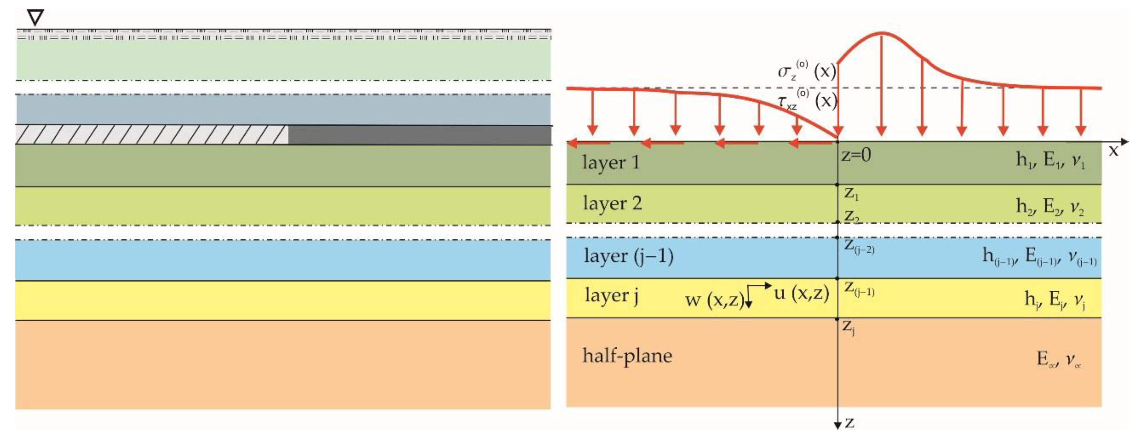
2.1. A Geomechanical Model of the Stratified Rock Mass

As a consequence of the increasing mining depth, the multi-seam structure of coal deposits and the related order of extracting seams (from the higher to lower level, which seems justified), the impacts of mining remnants on the buildup of stress and on displacements in the underlying rock strata have become a major concern. The developed geomechanical model of the stratified rock mass is based on the following assumptions (Figure 2) [28,53]:
-
The specificity of the mining remnants is modeled by an appropriate distribution of stresses or displacements.
-
Due to the order of seam extraction (from top to bottom), the analysis of impacts of the mining remnants is focused on the bottom level rock strata.
-
Between the mining remnants and the studied level, zj−1, there are n layers (n = 1, 2, 3 … j) constituting homogeneous, isotropic and contained elastic bands with the following parameters: h j thickness (m), E j ,   v j strain modulus (Pa), Poisson ratio (−).
-
Rock formations underlying the level zj are modeled by a homogeneous and isotropic elastic half-plane with the following strain parameters: E ,   v (Pa, −).
-
Interactions between the contacting layers involve sliding (no friction and cohesion), cohesive and frictional effects.
-
The 2D state of stress is assumed.
In the light of these assumptions, the development of the state of stress in the stratified rock mass was reduced to the problem of determining the magnitude of stresses in the interacting elastic bands [74,75,76]. The biharmonic equation is satisfied in each band and in the underlying half-plane:
4 F j ( x , z ) x 4 + 2 4 F j ( x , z ) x 2 z 2 + 4 F j ( x , z ) z 4 = 0
where F j ( x , z ) stress function defining the components of the stress tensor: σ x ( j ) ( x , z ) , σ z ( j ) ( x , z ) , τ x z ( j ) ( x , z ) and the displacement vector u ( j ) ( x , z ) , w ( j ) ( x , z ) in the jth layer. These components are defined by the respective formulas:
σ x ( j ) ( x , z ) = 2 F j ( x , z ) z 2 σ z ( j ) ( x , z ) = 2 F j ( x , z ) x 2 τ x z ( j ) ( x , z ) = 2 F j ( x , z ) z x
{ 2 G j u ( j ) ( x , z ) x = ( 1 ν j ) 2 F j ( x , z ) x 2   ν j 2 F j ( x , z ) z 2 2 G j w ( j ) ( x , z ) z = ( 1 ν j ) 2 F j ( x , z ) z 2   ν j 2 F j ( x , z ) x 2
where:
G = E j 2 ( 1 + ν j )
Thus, the problem of solving the biharmonic equation can be brought down to finding the appropriate stress functions, F j ( x , z ) . The problem can be solved via the complex Fourier integral transform [77,78]) and the simple transforms of a function Φ ¯ ( α , z ) are defined accordingly:
Φ ¯ ( α , z ) = d f Φ ( x , z ) e i α x d x
and the inverse transforms Φ ( x , z ) are expressed by the formula:
Φ ( x , z ) = d f 1 2 π Φ ¯ ( α , z ) e i α x d α
The transform of the stress function, F ¯ j ( α , z ) , for the jth layer becomes:
F ¯ j ( α , z ) = ( A j + B j z ) e α z + ( C j + D j z ) e α z
and the transform of the stress function for the half-plane F ¯ ( α , z ) is represented by the following relationship:
F ¯ ( α , z ) = ( C + D z ) e α z
where A j , B j , C j , D j , C , D ,  are integration constants obtained from the relevant boundary conditions.
The transforms of respective components of the stress tensor σ ¯ x ( j ) ( α , z ) , σ ¯ z ( j ) ( α , z ) , τ ¯ x z ( j ) ( α , z ) and the displacement vector u ¯ ( j ) ( α , z ) , w ¯ ( j ) ( α , z ) in the considered layers and in the underlying half-plane are given by:
σ ¯ x ( j ) ( α , z ) = 2 F ¯ j ( α , z ) z 2 σ ¯ z ( j ) ( α , z ) =   α 2 F ¯ j ( α , z ) τ ¯ x z ( j ) ( α , z ) = i α F ¯ j ( α , z ) z
u ¯ ( j ) ( α , z ) = i 2 G j α [ ( 1 ν j ) 2 F ¯ j ( α , z ) z 2 + ν j α 2 F ¯ j ( α , z ) ] w ¯ ( j ) ( α , z ) = 1 2 G j α 2 [ ( 1 ν j ) 3 F ¯ j ( α , z ) z 3 + α 2 ( ν j 2 ) F ¯ j ( α , z ) z ]
The integration constants present in the component transforms of the stress tensor and the displacement vector are derived after adoption of appropriate boundary conditions. Two groups of conditions can be distinguished:
-
Conditions at the level of the mining remnants, modeled accordingly by an appropriate distribution of stresses or displacements (mixed boundary conditions are also possible);
-
Conditions defining the interactions between the contacting layers, taking into account different contact variants: with no friction or involving cohesive and frictional effects.

2.2. Boundary Conditions

The boundary conditions that define the state of stress and displacement are given by the following expressions [53]:
-
At the level of mining remnants: for z = 0
{ σ ¯ z ( o ) ( α ) = σ ¯ z ( 1 ) ( α , 0 ) τ ¯ x z ( o ) ( α ) = τ ¯ x z ( 1 ) ( α , 0 )
or
{ w ¯ ( o ) ( α ) = w ¯ ( 1 ) ( α , 0 ) u ¯ ( o ) ( α ) = u ¯ ( 1 ) ( α , 0 )
-
On the interface level: (j−1) and jth for z = zj
Regardless of the type of contact between the layers, there is a continuity of vertical stresses and vertical displacements. Hence, for all the analyzed variants of interaction between the contacting layers, for z = zj the following equations will be satisfied:
{ σ ¯ z ( j 1 ) ( α , z j ) = σ ¯ z ( j ) ( α , z j ) w ¯ ( j 1 ) ( α , z j ) = w ¯ ( j ) ( α , z j )
Other boundary conditions, depending on the actual interface effects, are defined by the following relationships:
  • Variant I—Cohesion force arising on the interface between the layers (the so-called “stitching” of layers)
{ τ ¯ x z ( j 1 ) ( α , z j ) = τ ¯ x z ( j ) ( α , z j ) u ¯ z ( j 1 ) ( α , z j ) = u ¯ z ( j ) ( α , z j )
  • Variant II—No cohesion or friction forces acting on the interface between layers (so-called “slippage” effect)
{ τ ¯ x z ( j 1 ) ( α , z j ) = 0 τ ¯ x z ( j ) ( α , z j ) = 0
  • Variant III—Friction forces arising on the interface between layers
{ τ ¯ x z ( j 1 ) ( α , z j ) = μ σ ¯ z ( j 1 ) ( α , z j ) τ ¯ x z ( j 1 ) ( α , z j ) = τ ¯ x z ( j ) ( α , z j )
where μ is the coefficient of friction (−).
In order to determine the integration constants from the above boundary conditions, a system of (4j−2) algebraic equations should be solved and the inverse Fourier transforms of the stress tensor components can be derived.

2.3. A System Modeling the Impact of Mining Remnants on a Multi-Layer Medium

Due to the complexity of the resulting formulas, closed analytical expressions are not available, hence appropriate numerical programs were developed to evaluate the influence of geomechanical parameters of layers on the developed state of stress. Consequently, a system was considered in which (Figure 3):
-
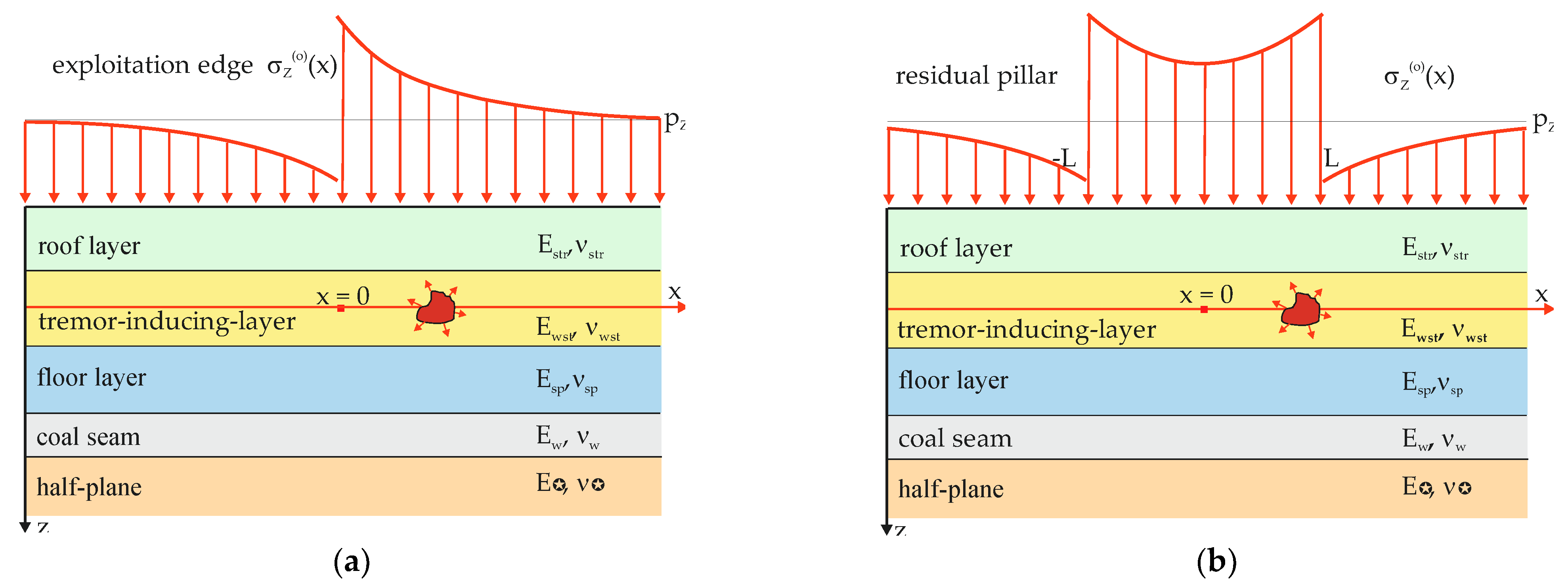
The mining remnants are modeled by an uneven distribution of additional vertical stresses, σ z ( o ) ( x ) , corresponding to the conditions on the left exploitation edge or the residual pillar.
-
There are four layers between the mining remnants and the elastic half-plane, including the tremor-inducing layer and the seam.
-
The “stitching” or “slipping” effects occur on the interface between the layers.
Since the influence of the mining remnants on the surrounding rock mass is the result of non-uniform stress distribution, the concept of an additional stress, σ z ( o ) ( x ) , resulting from the mining remnants was adopted for further consideration:
σ z ( o ) ( x ) = p z ( x ) p z
where: p z ( x ) is the value of the vertical component in the secondary stress state and p z is value of the vertical component in the original stress state.
The following expressions were used to determine the additional stresses resulting from the presence of mining remnants [24]:
-
In the case of the exploitation edge (Figure 4):
-
For goafs:
L x L σ z ( o ) ( x ) = p z cosh ( δ P x ) cosh δ P L
-
For undisturbed coal body:
< x L σ z ( o ) ( x ) = p z E w E p t g h ( δ p L ) e   δ w ( x + L )  
L x < σ z ( o ) ( x ) = p z E w E p t g h ( δ p L ) e   δ w ( x   L )  
where: p z is the value of the vertical component in the primary state of stress on the level of the mining remnants:
p z = γ H z
where: γ is volumetric mass of the overlying rocks (N/m3), Hz is depth of the occurrence of the mining remnants (m),
δ p = 3 E p E F h w
δ w = 3 E w E F h w
where: E w is the Young modulus of the seam (Pa), E p is Young modulus of the goafs (Pa), h w is height of the seam (goafs) (m), 2 L is the goaf width (m) and E F is equivalent rigidity (N/m).
-
In the case of a residual pillar (Figure 5):
-
For goafs:
< x L σ z ( o ) ( x ) = p z e   δ p 1 ( x + L )  
L x > σ z ( o ) ( x ) = p z e   δ p 2 ( x L )  
where:
α = 3 E w z E s F h
α = 3 E w z E s F h
where: E p 1 , E p 2 are Young moduli of the goafs (Pa, −) and 2 L 1 is the pillar width (m)
-
For pillars:
L x L σ z ( o ) ( x ) = ϑ 1 cosh [ δ w ( x + L ) ] + ϑ 2 cosh [ δ w ( x L ) ] sinh ( 2 δ w L )
where: ϑ 1 , ϑ 2 are parameters expressing the impact of the goafs:
ϑ 1 = p z E w E p 1
ϑ 2 = p z E w E p 2
The Fourier transforms of these functions required to identify boundary conditions are derived from the respective formulas:
-
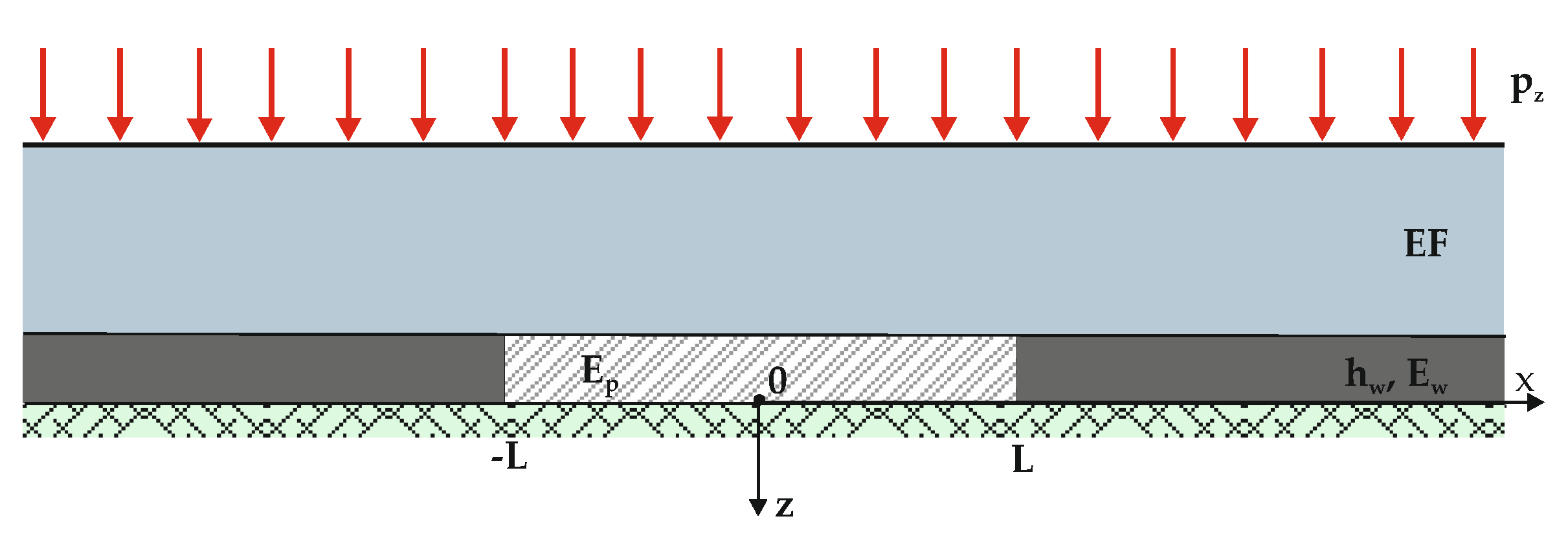
For the exploitation edge:
σ ¯ z ( o ) ( α ) = 2 p z ( α sin ( α L ) + δ p cos ( α L ) t g h ( δ p L ) δ p 2 + α 2 + δ w t g h ( δ p L ) [ α sin ( α L ) δ w cos α L ] δ p ( δ w 2 + α 2 ) )
-
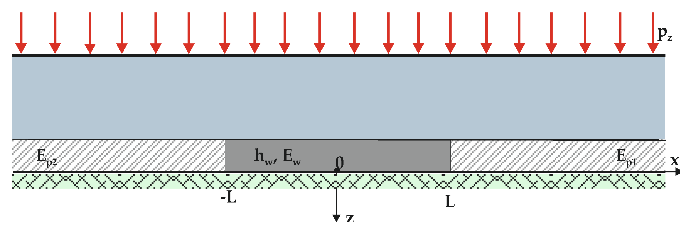
For a residual pillar:
σ ¯ z ( o ) ( α ) = 2 p z ( δ w [ α sin ( α L ) 1 + cosh ( 2 δ w L ) + δ w cos ( α L ) sinh ( 2 δ p L ) ] δ p sinh ( 2 δ p L ) ( δ w 2 + α 2 ) + α sin ( α L ) δ p cos ( α L ) δ p 2 + α 2 )
The boundary conditions for the model have the same form as those given in earlier sections, accounting for cohesive contact (cohesion forces) or the sliding contact (without cohesion forces) at the interface between layers.

2.4. Variability of the Specific Strain Energy

External loads acting on the rock strata due to the presence of mining remnants will cause the elastic strain energy to change. The total specific strain energy, A v d o d , embracing the changes of both volume and form, A v d o d and A f d o d , is given as [79]:
A c d o d = A v d o d + A f d o d
These energies are defined by the following expressions:
A v d o d = 1 2 ν 6 E ( σ x + σ y + σ z ) 2
A f d o d = 1 + ν 6 E [ ( σ x σ y ) 2 + ( σ y σ z ) 2 + ( σ z σ x ) 2 + 6 ( τ x y 2 + τ y z 2 + τ z x 2 ) ]
However, in the case of the 2D state of strain, there are additional dependencies:
σ z = ν ( σ x + σ y ) τ x y = τ y z = 0
The presence of mining remnants causes a change in the primary total specific strain energy, A c , resulting in a non-uniform accumulation of the secondary strain energy, A c , around those remnants. It is expressed by the relationship:
A c = A c + A c d o d
Similarly, the secondary energies of volumetric and shear strain, A v and A f , respectively, can be derived from the formulas:
A v = A v + A v d o d
A f = A f + A f d o d
where: A v is primary energy of volumetric strain and A f primary energy of shear strain.
The process of fracturing of the tremor-inducing layer, leading to a tremor, can occur as long as the state of stress in this layer reaches the critical state defined by the relevant stress-strain hypothesis. Assuming the tremor coming as a result of exceeding the rock strength and recalling the Burzyński’s energy criterion [72,73], it appears that exceeding the critical stress of the rock mass is determined by shear strain energy and a certain portion of the energy of volumetric strain (associated with the state of strain and strength properties):
A k r = A f + κ A v
where: κ is parameter from Burzyński’s stress hypothesis ( 0 κ 1 ).
The remaining portion of energy is kinetic energy, Ask, proportional to the seismic energy of the tremor, Ask:
A s k = ( 1 κ ) A v
The numerical program based on analytical solutions was used to assess the impacts of the technological parameters of previous mining operations in the seam underlying the tremor-inducing layer and the impacts that the stress-strain properties of the layers have on development of the state of stress in the zone affected by the presence of exploitation edges and residual pillars. The calculated distributions of the stress tensor components in the tremor-inducing layer afford us the means to analyze changes in the specific strain energy and, consequently, to assess the impact of the mining remnants on the development of the tremor hazard conditions.

3. Results and Discussion

The analysis of variability in volumetric and shear strain energies was based on the energy concentration coefficient A/A*, defined as the ratio of secondary energy, A*, to primary energy, A. Respective graphs show the distributions of these quantities in the central part of the tremor-inducing layer as the function of horizontal distance from the modeled mining remnants site. In the case of an exploitation edge, the coordinate x = 0 corresponds to the location of this edge, whilst the calculation results refer to a fragment of the modelled workings (L = 50 m) and the undisturbed coal body (Figure 3). For a 2L = 50 m wide residual pillar, the coordinate x = 0 marks the position of the pillar midpoint (Figure 4).
Input parameters to the calculation procedure were the geological conditions and mining data specific of the Upper Silesian Coal Basin, as well as technical parameters of the longwall mining system. Strain parameters of respective rock strata are summarized in Table 1.
The impacts of the exploitation edge and the residual pillar (Figure 3 and Figure 4) are modelled basing on the following parameters: Hz = 600 m; γ = 2.5 × 10⁴ N/m3; E p = E p 1 = E p 2 = 5.0 × 10⁷ Pa; E w = 2.5 × 10⁹ Pa; h w = 3 m; 2 L = 100 m (for edge), 50 m (for pillar); EF = 2.5 × 10¹¹ N/m.

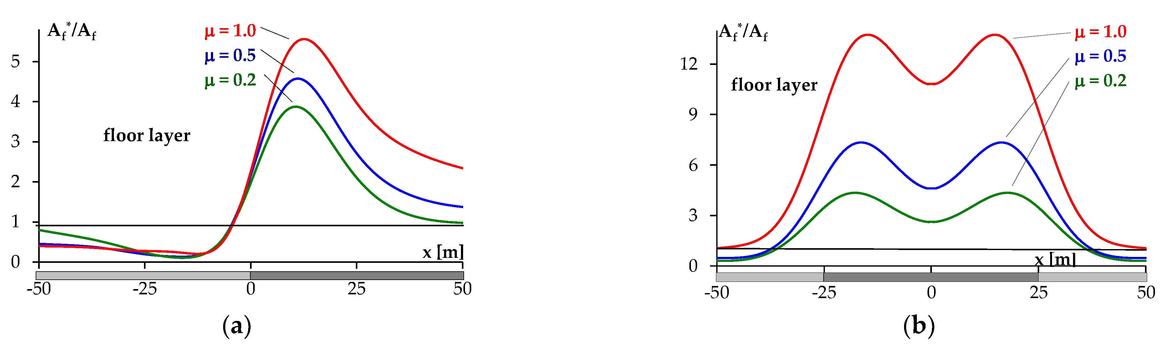
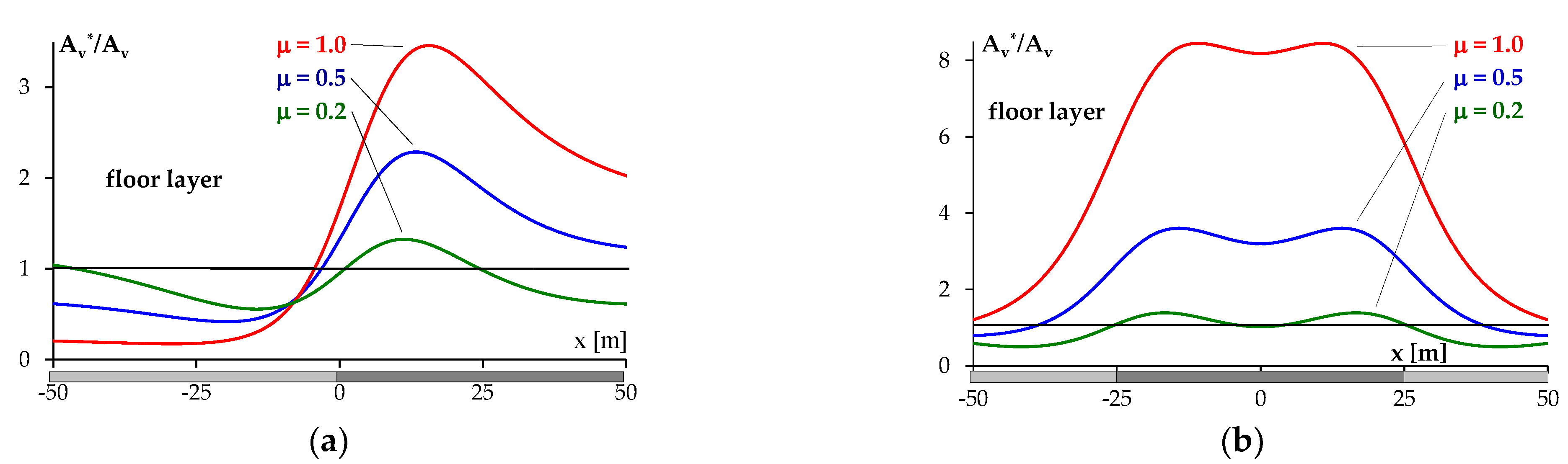
3.1. Development of Strain Energy Depending on the Strain Behavior of the Layers

The buildup of volumetric and shear strain energies was examined assuming different relationships between the strain properties of respective layers (Figure 2), expressed by the following parameter:
μ = E s t r ( s p ) ( 1 + ν w s t ) E w s t ( 1 + ν s t r ( s p ) )
where: Estr(sp)—Young modulus of the roof (floor) (Pa), Ewst—Young modulus of the tremor-inducing layer (Pa), νstr(sp)—Poisson ratio of the roof (floor) strata(−) and νwst—Poisson ratio of the tremor-inducing layer (−).
Input data used in the calculation procedure are: E s t r = 5 × 10⁹, 10 × 109, 15 × 109 Pa; E w s t = 15 × 109 Pa; E s p = 5 × 10⁹, 10 × 109, 15 × 109 Pa; E w = 2.5 × 10⁹ Pa; E = 7.5 × 10⁹ Pa; ν s t r = ν w s t = ν s p = ν = 0.25; ν w = 0.35; hstr = 10 m; hwst = 20 m; hsp = 10 m; hw = 3 m and the cohesion-type contact is assumed between the layers (the “stitching” effect).
Calculation results give us an insight into the impacts of strain properties of the roof l (Figure 6 and Figure 7) and floor strata (Figure 8 and Figure 9) in the following cases:
-
μ = 1.0—the roof/floor layer is the least deformable/prone to deformation,
-
μ = 0.5—the roof/floor layer is less deformable,
-
μ = 0.2—the roof/floor layer is the most deformable.
Graphs derived for the roof layer show that strain properties of the layer beneath the mining remnants (edge, pillar) and of the tremor-inducing layer determine the values of the strain energy in the tremor-inducing layer. The greatest concentrations of energy are registered in highly deformable formations between the mining remnants and the tremor-inducing layer. In the case when formations above the tremor-inducing layer are less prone to deformations, the energy concentration values are lower. Therefore, it can be concluded that a change in strain properties of the layers between the mining remnants and the tremor-inducing layer can affect the magnitude of the tremor hazard. The highest risk levels are associated with highly deformable layers between the remnants and the tremor-inducing layer. Enhancing the rigidity of the overlying strata will reduce the risk of failure and, consequently, the seismic energies of potential tremors will be limited. A change in the strain properties of the floor layer between the tremor-inducing layer and the seam will affect the values of strain energy in the tremor-inducing layer, though following the pattern that runs counter to that observed for the roof strata. The highest energy values are registered for weakly deformable formations between the tremor-inducing layer and the seam. High deformability of the floor layer causes a decrease in the energy value, thus reducing the tremor hazard.

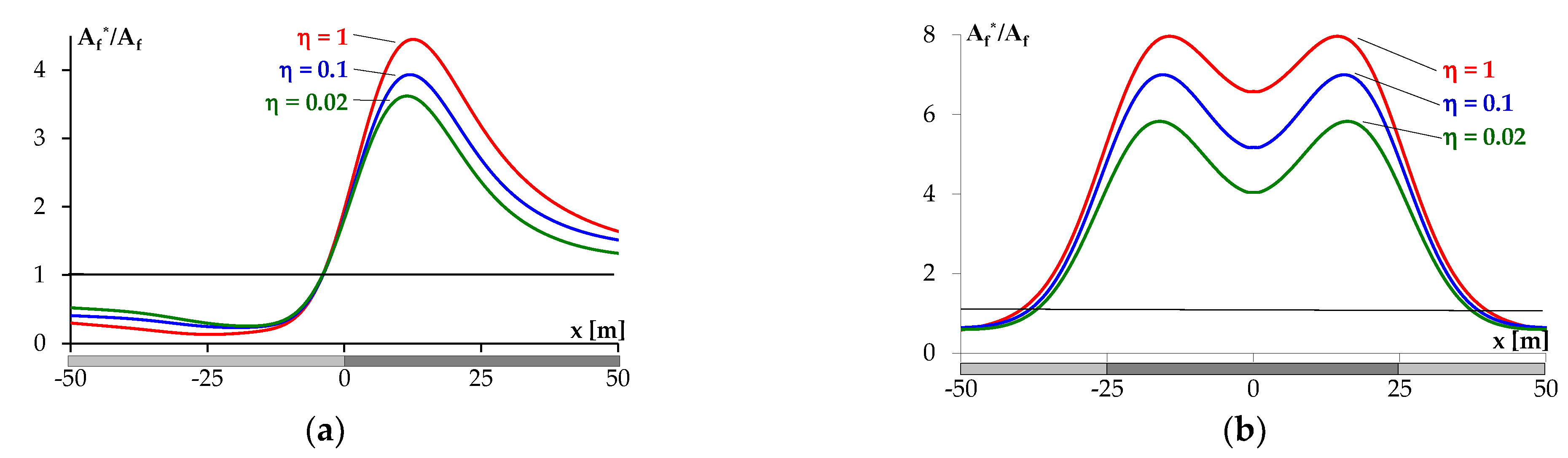
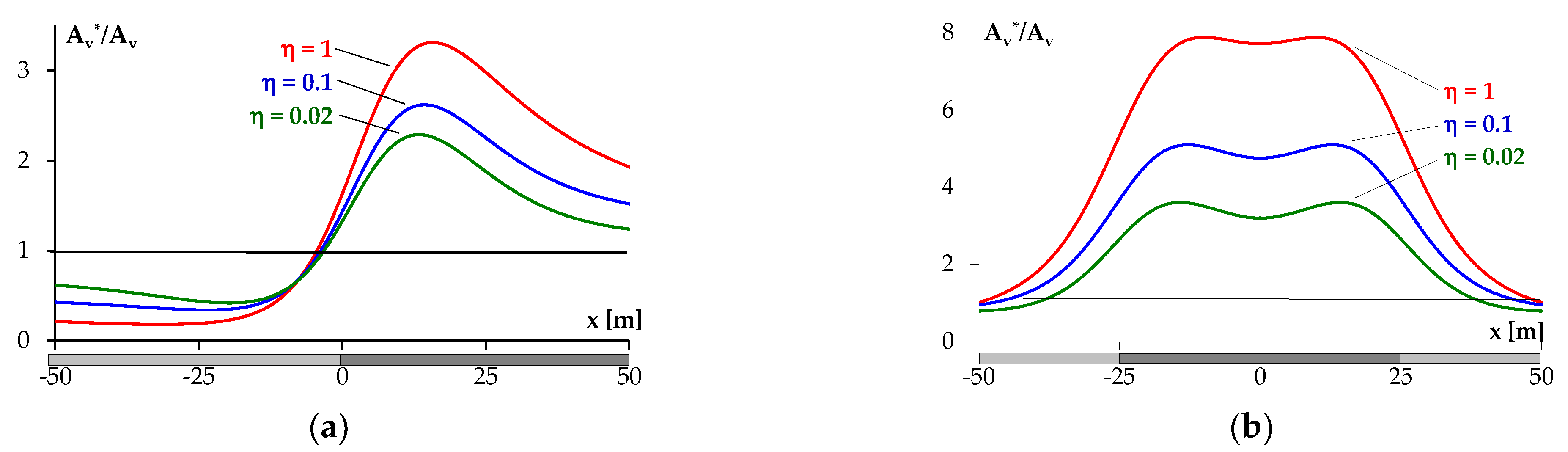
3.2. Buildup of Strain Energy Depending on the Method of Liquidation of the Goafs

The method used in the analysis of volumetric and shear strain energy allowed the presence of goafs in the seam beneath the tremor-inducing layer to be neglected, and the relationships between the strain moduli of the goafs and the coal seam (Figure 3) were defined by the parameter:
η = E p E w
where: Ep is strain modulus of the goafs in the seam underlying the tremor-inducing layer (Pa) and Ew is strain modulus of the coal seam underlying the tremor-inducing layer (Pa)
Input data to the calculation procedure: Ep = 2.5 × 10⁸ Pa (for hydraulic backfilling), 5 × 10⁷ Pa (for cave-in) and, the absence of cohesion (the “slipping” effect) forces is assumed in the case of mining operations on the interface between the coalbed layer and the half-plane.
Relationships in (Figure 10 and Figure 11) illustrate the following mining conditions:
-
η = 1—the seam has not been extracted,
-
η = 0.1—the seam has been extracted by the hydraulic filling method,
-
η = 0.02—the seam has been extracted after caving-in of the roof.
These distribution patterns show that the highest concentrations of shear and volumetric strain energies in the tremor-inducing layer occur in the vicinity of undisturbed coal body on the exploitation edge and in residual pillars. Thus, the foci of tremors caused by fracturing of the tremor-inducing layer will be located in the regions that were unmined and undisturbed during past mining operations.
The extraction of a coal seam underlying the tremor-inducing layer results in a decrease in the magnitude of shear and volumetric strain energy in this particular layer and the energy values are found to be the smallest in the scenario involving roof cave-in. Thus, the extraction of subsequent seams will present a lower seismic risk due to fracturing of the tremor-inducing layer.

4. Conclusions

The analysis of impacts that the presence of mining remnants has on elastic strain energy arising in the tremor-inducing layer leads us to the following conclusions:
-
The impacts of previous mining operations lead to changes in the primary state of stress, revealed as non-uniform distributions of the total strain energy, being the sum of the volumetric and shear strain. In stress-relief zones, the secondary strain energy tends to decrease whilst in the elevated stress zones the strain energy increases.
-
The mining remnants can, under certain conditions, lead to exceeding the critical stress in the rock strata and, consequently may trigger rock failure. Specifically, the fracturing in tremor-inducing layers is likely to trigger the tremor occurrence.
-
Extraction of the underlying seam in the area affected by the tremor-inducing layer will reduce the risk of tremor occurrence in this layer and the magnitude of seismic energy of potential tremors. The risk level will be the lowest when the seam is mined following the caving-in of the roof beneath the tremor-inducing layer.
-
The strain properties of rock layers in the vicinity of the tremor-inducing layer will determine the tremor hazard level.
-
The risk will be the greatest where there are highly deformable formations between the mining remnants and the tremor-inducing layer. As these layers have high rigidity, the tremor-inducing layer is less likely to fracture, which limits the seismic energy of potential tremors.
-
In the case of formations underlying the burst-prone strata, the reverse is observed. High deformability of strata results in a decrease in the tremor hazard level as seismic activity of the tremor-inducing layer will be reduced.
-
The tremor hazard level can be reduced by adopting the roof control strategy involving caving-in, thus enhancing the deformability of the immediate roof layers, or by taking appropriate preventive measures (e.g., stress-relieving blasting, rock loosening watering) to cater for various types of fracturing. Therefore, the tremor hazard can be effectively reduced not only through stress-relieving blasting in the tremor-inducing layer, but also by de-stressing the underlying formations.
The conclusions clearly highlight the impacts that mining and geomechanical parameters of rock strata have on the tremors hazard level in the vicinity of mining remnants, suggesting the mitigation schemes. Generally, these conclusions are in line with the expertise of maintenance engineers in rockburst-prone coal mines.
Even though in qualitative terms the stress distributions in stratified media are close to those obtained by well-known solutions applicable to homogeneous media, there are still major quantitative differences. That is why it is fully merited to assume the stratified structure of the rock mass in evaluations of the state of stress and tremor hazard in the vicinity of mining remnants.

Author Contributions

Conceptualization, Z.B.; methodology, Z.B.; software, Z.B. and D.C.; validation, Z.B. and D.C.; formal analysis, Z.B. and D.C.; investigation, Z.B. and D.C.; resources, D.C.; data curation, D.C.; writing—original draft preparation, Z.B. and D.C.; writing—review and editing, Z.B.; visualization, D.C.; supervision, Z.B. All authors have read and agreed to the published version of the manuscript.

Funding

The article was funded by AGH University of Science and Technology, Faculty of Civil Engineering and Resource Management (subsidy no. 16.16.100.215).

Institutional Review Board Statement

Not applicable.

Informed Consent Statement

Not applicable.

Data Availability Statement

The data analysed in article are available on request from the corresponding author (not publicly available).

Conflicts of Interest

The authors wish to confirm that there are no known conflict of interest associated with this publication.

References

  1. Burtan, Z.; Chlebowski, D. Natural hazard conditions resulting in major accidents in the coal-mining sector in Poland. In Proceedings of the 25th World Mining Congress, Astana, Kazakhstan, 19–21 June 2018; pp. 62–71. [Google Scholar]
  2. State Mining Authority. Evaluation of Work Safety, Mine Rescue Systems and General Safety Features in Connection with Geological and Mining Activities in 2020 Katowice; State Mining Authority: Katowice, Poland, 2021. (In Polish) [Google Scholar]
  3. Dymek, F. State of stress and strain in rock strata on top of the seam being mined, in the light of the linear theory of elasticity. Arch. Min. Sci. 1961, 6, 283–314. (In Polish) [Google Scholar]
  4. Dymek, F. Applications of the elastic half-plane concept to solving problems of strata mechanics. J. AGH-UST 1963, 9, 17–55. (In Polish) [Google Scholar]
  5. Dymek, F. Selected 2D and 3D solutions for rheological media and their applications to strata mechanics. Arch. Min. Sci. 1973, 17, 123–144. (In Polish) [Google Scholar]
  6. Dymek, F. The state of stress and strain in the around a horizontal excavation. Arch. Min. Sci. 1973, 18, 413–419. (In Polish) [Google Scholar]
  7. Dymek, F. Selected boundary problems in theory of elasticity and visco-elasticity having relevance to rock strata mechanics. Arch. Min. Sci. 1974, 19, 117–142. (In Polish) [Google Scholar]
  8. Dymek, F.; Dymek, J.F. Selected solutions for a transversely isotropic medium and their applications in strata mechanics. J. AGH-UST 1985, 1, 73–93. (In Polish) [Google Scholar]
  9. Dymek, F.; Dymek, J.F. Solution of the state of strain and displacement for an elastic, transversely isotropic medium. J. AGH-UST 1987, 1, 5–16. (In Polish) [Google Scholar]
  10. Jóźkiewicz, S.; Kłeczek, Z. The impacts of the abandoned exploitation edge on mining conditions in overlying and underlying seams. J. AGH-UST 1972, 36, 29–38. (In Polish) [Google Scholar]
  11. Korman, S. The state of stress in rock strata underneath the seam being mined. Part I—Theoretical backgrounds. Arch. Min. Sci. 1957, II/3, 114–128. (In Polish) [Google Scholar]
  12. Golecki, J.; Jóźkiewicz, S. The impacts of underground mining operations on rock strata deformation in the light of the theory of elasticity. Przegląd. Górniczy. 1963, 19/6, 253–258. (In Polish) [Google Scholar]
  13. Gil, H. The state of stress and strain in an infinite elastic-plastic region and its applications in rock mechanics. Arch. Min. Sci. 1964, 9/1, 46–63. (In Polish) [Google Scholar]
  14. Gil, H. Stress and strain distribution in rock strata modelled as a visco-elastic medium. Arch. Min. Sci. 1965, 3/1, 16–29. (In Polish) [Google Scholar]
  15. Gil, H. Distribution of displacements in a horizontal section comprising loose and elastic medium caused by mixed boundary stress conditions. Arch. Min. Sci. 1966, XI/4, 377–385. (In Polish) [Google Scholar]
  16. Gil, H.; Czypionka, S. The impacts of exploitation Edge in discontinued mining operation on overlying and underlying seams. Przegląd Górniczy 1973, 5, 181–183. (In Polish) [Google Scholar]
  17. Gil, H.; Czypionka, S.; Krzyżowski, A. Determining the hazard zone when the working face is approaching the goafs left from previous mining operations and the existing egdes in overlying or underlying seams. J. Sil. Polytech. 1976, 70, 43–52. (In Polish) [Google Scholar]
  18. Gil, H. The Theory of strata Mechanics. In PWN Warszawa; Elsevier: Amsterdam, The Netherlands; Oxford, UK; New York, NY, USA; Tokyo, Japan, 1991. [Google Scholar]
  19. Gil, H.; Kraj, W. The distribution of displacements and stresses in rocks in an abandoned working face. Arch. Min. Sci. 1974, 19, 1. (In Polish) [Google Scholar]
  20. Chudek, M.; Stefański, L. Stress and strain in rock strata in the vicinity of longwall workings, mining remnants and protective pillars in underground mines. J. Sil. Polytech. 1985, 136, 401–412. (In Polish) [Google Scholar]
  21. Chudek, M.; Stefański, L. The impacts of underground mining on deformation of stratified rock mass. J. AGH-UST 1989, 145, 214–226. (In Polish) [Google Scholar]
  22. Szpetkowski, S. The course and activation values of seam mining operations. Arch. Min. Sci. 1979, 24/3, 313–336. (In Polish) [Google Scholar]
  23. Szpetkowski, S. Predicting the Impacts of Mining Operations on the Rock Strata and Ground Surface; Silesian Technical Publishers: Katowice, Poland, 1995. (In Polish) [Google Scholar]
  24. Kłeczek, Z.; Zorychta, A. The impacts of old excavations on the state of strain in burst-prone rock strata. J. Sil. Polytech. 1990, 185, 7–34. (In Polish) [Google Scholar]
  25. Zorychta, A.; Burtan, Z.; Chlebowski, D. The influence of the width of longwall gob on the value of stress under the edges of the exploitation area. In Proceedings of the Application of Computer Methods in Rock Mechanic—Proceedings of International Symposium on Application of Computer Methods in Rock Mechanics and Engineering (Volume 2), Xi’an, China, 24 May 1993. [Google Scholar]
  26. Chlebowski, D.; Burtan, Z.; Cieślik, J.; Zorychta, A. The state of stress and stress in the longwall face underneath the exploitation edge of previous mining activities. J. IGSMiE Pol. Akad. Nauk. 2017, 99, 159–170. (In Polish) [Google Scholar]
  27. Chlebowski, D.; Burtan, Z.; Zorychta, A. Evaluation of rockburst hazard under abandoned mine workings. Arch. Min. Sci. 2018, 63, 687–699. [Google Scholar]
  28. Zorychta, A.; Burtan, Z. The effects of stratified rock medium on development of the state of stress and rockburst hazard levels. Res. Pap. Cent. Min. Inst. 1998, 26, 119–132. (In Polish) [Google Scholar]
  29. Avierszyn, S.G. Rock Movements in Underground Mining; Ugletieichnizdat: Moskwa, Russia, 1947. (In Russian) [Google Scholar]
  30. Avierszyn, S.G. Rock Bursts; Ugletieichnizdat: Moskwa, Russia, 1955. (In Russian) [Google Scholar]
  31. Pietuchow, I.M. Rock Bumps in Coal Mines; Niedra: Moskwa, Russia, 1972. (In Russian) [Google Scholar]
  32. Pietuchow, I.M.; Linkow, A.M.; Sidorow, W.S.; Feldman, I.A. Theory of Protective Seams; Niedra: Moskwa, Russia, 1976. (In Russian) [Google Scholar]
  33. Everling, G. Application of Rock Mechanics in Deep Coal Mines. In Proceedings of the Third Congress ISRM, Washington, DC, USA, 1–7 September 1974. [Google Scholar]
  34. Salamon, M.D.G. Rock Mechanics of underground Excavation. In Proceedings of the Third Congress ISRM, Washington, DC, USA, 1–7 September 1974. [Google Scholar]
  35. Zhou, Y.; Haycocks, C. Designing for Upper Seam Stability in Multiple Seam Mining. In Proceedings of the Fifth Conference on Ground Control in Mining, Morgantown, Virginia, 11–13 June 1986. [Google Scholar]
  36. Alber, M.; Fritschen, R.; Bischoff, M.; Meier, T. Rock mechanical investigations of seismic events in a deep longwall coal mine. Int. J. Rock Mech. Min. Sci. 2009, 46, 408–420. [Google Scholar] [CrossRef]
  37. Singh, A.K.; Singh, R.; Maiti, J.; Kumar, R.; Mandal, P. Assessment of mining induced stress development over coal pillars during depillaring. Int. J. Rock Mech. Min. Sci. 2011, 48, 805–818. [Google Scholar] [CrossRef]
  38. Suchowerska, A.M.; Merifield, R.S.; Carter, J.P. Vertical stress changes in multi-seam mining under super-critical longwall panels. Int. J. Rock Mech. Min. Sci. 2013, 61, 306–320. [Google Scholar] [CrossRef]
  39. Haijun, J.; Shenggen, C.; Yun, Z.; Wang, C. Analytical solutions of hard roof’s bending moment, deflection and energy under the front abutment pressure before periodic weighting. Int. J. Min. Sci. Technol. 2016, 26, 175–181. [Google Scholar]
  40. Wang, W.; Jiang, T.; Wang, Z.; Ren, M. A analytical model for cover stress re-establishment in the goaf after longwall caving mining. J. S. Afr. Inst. Min. Metall. 2017, 117, 671–683. [Google Scholar] [CrossRef]
  41. Dong, X.; Karrech, A.; Basarir, H.; Elchalakani, M.; Qi, C. Analytical solution of energy redistribution in rectangular openings upon in-situ rock mass alteration. Int. J. Rock Mech. Min. Sci. 2018, 106, 74–83. [Google Scholar] [CrossRef]
  42. Zhang, Q.; Peng, C.H.; Liu, R.C.; Jiang, B.S.; Lu, M.M. Analytical solutions for the mechanical behaviors of a hard roof subjected to any form of front abutment pressures. Tunn. Undergr. Space Technol. 2019, 85, 128–139. [Google Scholar] [CrossRef]
  43. Feng, G.; Wang, P. Simulation of recovery of upper remnant coal pillar while mining the ultra-close lower panel using longwall top coal caving. Int. J. Min. Sci. Technol. 2020, 30, 55–61. [Google Scholar] [CrossRef]
  44. Wang, X.; Guan, K.; Yang, T.; Liu, X. Instability mechanism of pillar burst in asymmetric mining based on cusp catastrophe model. Rock Mech. Rock Eng. 2021, 54, 1463–1479. [Google Scholar] [CrossRef]
  45. Maleki, H. Coal pillar mechanics of violent failure in U.S. Mines. Int. J. Min. Sci. Technol. 2017, 27, 387–392. [Google Scholar] [CrossRef]
  46. Li, Z.; Dou, L.; Cai, W.; Wang, G.; He, J.; Gong, S.; Ding, Y. Investigation and analysis of the rock burst mechanism induced within fault-pillars. Int. J. Rock Mech. Min. Sci. 2014, 70, 192–200. [Google Scholar] [CrossRef]
  47. Tulu, I.B.; Esterhuizen, G.S.; Klemetti, T.; Murphy, M.M.; Sumner, J.; Sloan, M. A case study of multi-seam coal mine entry stability analysis with strength reduction method. Int. J. Min. Sci. Technol. 2016, 26, 193–198. [Google Scholar] [CrossRef]
  48. Klemetti, T.M.; Sears, M.M.; Tulu, I.B. Design concerns of room and pillar retreat panels. Int. J. Min. Sci. Technol. 2017, 27, 29–35. [Google Scholar] [CrossRef]
  49. Zhang, P.; Tulu, B.; Sears, M.M.; Trackemas, J. Geotechnical considerations for concurrent pillar recovery in close-distance multiple seams. Int. J. Min. Sci. Technol. 2018, 28, 7–21. [Google Scholar] [CrossRef]
  50. Salamon, M.D.G. An Introductory Mathematical Analysis of the Movements and Stresses Induced by Mining in Stratified Rocks; King’s College: London, UK; University of Durham, Department of Mining: Durham, UK, 1961. [Google Scholar]
  51. Salamon, M.D.G. Elastic analysis of displacements and stresses induced by the mining of seam or reef de-posits, Part I. J. S. Afr. Inst. Min. Metall. 1963, 64, 128–149. [Google Scholar]
  52. Salamon, M.D.G. Deformation of stratified rock masses: A laminated model. SAIMM—J. South. Afr. Inst. Min. Metall. 1991, 91, 9–25. [Google Scholar]
  53. Burtan, Z. Geomechanical model of stratified rock mass. Yearb. AGH-UST 2010, 34, 33–42. (In Polish) [Google Scholar]
  54. Burtan, Z. Geomechanical model of a transversely isotropic medium as a simplified model of stratified rock mass. Yearbook AGH-UST 2011, 35, 13–22. (In Polish) [Google Scholar]
  55. Salamon, M.D.G. Elastic moduli of a stratified rock mass. Int. J. Rock Mech. Sci. 1968, 5, 519–527. [Google Scholar] [CrossRef]
  56. Wardle, L.J.; Gerrard, C.M. The “equivalent” anisotropic properties of layered rock and soil masses. Rock Mech. 1972, 4, 155–175. [Google Scholar] [CrossRef]
  57. Jiang, X.; Shuchun, L.; Guangzhi, Y. Nonlinear Deformation and Damage Characteristics of Rock under Cyclic Loading; Science Press: Beijing, China, 2012. [Google Scholar]
  58. Chudek, M. Rockbursts in stratified rock strata. J. Sil. Polytech. 1990, 185, 81–117. (In Polish) [Google Scholar]
  59. Shou, K. A two-dimensional displacement discontinuity method for multilayered elastic media. Int. J. Rock Mech. Min. Sci. 1997, 288, 3–4. [Google Scholar] [CrossRef]
  60. Zhou, N.; Liu, H.; Zhang, J.; Yan, H. Study on rock burst event disaster and prevention mechanisms of hard roof. Adv. Civ. Eng. 2019, 1, 6910139. [Google Scholar] [CrossRef]
  61. Zhang, C.; Canbulat, I.; Tahmasebinia, F.; Vardar, O.; Saydam, S. Analysis of a potential coalburst phenomenon in different strata layers in underground coal mines. In Deep Mining 2017: Proceedings of the Eighth International Conference on Deep and High Stress Mining; Wesseloo, J., Ed.; Australian Centre for Geomechanics: Perth, Australia, 2017; pp. 413–422. [Google Scholar]
  62. Ju, Y.; Wang, Y.; Su, C.; Zhang, D.; Ren, Z. Numerical analysis of the dynamic evolution of mining-induced stresses and fractures in multi-layered rock strata using continuum-based discrete element methods. Int. J. Rock Mech. Min. Sci. 2019, 113, 191–210. [Google Scholar] [CrossRef]
  63. Zhengyi, T.; Jiazhen, L.; Meng, W.; Kang, W.; Zhupeng, J.; Caiwang, T. Fracture Mechanism in Overlying Strata during Longwall Mining. Shock. Vib. 2021, 2021, 4764732. [Google Scholar]
  64. Ji, S.; He, H.; Karlovšek, J. Application of superposition method to study the mechanical behaviour of overlying strata in longwall mining. Int. J. Rock Mech. Min. Sci. 2021, 146, 104874. [Google Scholar] [CrossRef]
  65. Pan, C.; Xia, B.; Zuo, Y.; Yu, B.; Ou, C. Mechanism and control technology of strong ground pressure behavior induced by high-position hard roofs in extra-thick coal seam mining. Int. J. Min. Sci. Technol. 2022, 33, 499–511. [Google Scholar] [CrossRef]
  66. Shen, B.; King, A.; Guo, H. Displacement, stress and seismicity in roadway roofs during mining-induced failure. Int. J. Rock Mech. Min. Sci. 2008, 45, 672–688. [Google Scholar] [CrossRef]
  67. Marcak, H. Seismicity in mines due to roof layer bending. Arch. Min. Sci. 2012, 57, 229–250. [Google Scholar]
  68. Fan, J.; Dou, L.; He, H.; Du, T.; Zhang, S.; Gui, B.; Sun, X. Directional hydraulic fracturing to control hard-roof rockburst in coal mines. Int. J. Min. Sci. Technol. 2012, 22, 177–181. [Google Scholar] [CrossRef]
  69. Bräuner, G. Rockbursts in Coal Mines and Their Prevention; Routledge: London, UK, 2017. [Google Scholar]
  70. Huang, B.; Liu, J.; Zhang, Q. The reasonable breaking location of overhanging hard roof for directional hydraulic fracturing to control strong strata behaviors of gob-side entry. Int. J. Rock Mech. Min. Sci. 2018, 103, 1–11. [Google Scholar] [CrossRef]
  71. Tahmasebinia, F.; Zhang, C.; Canbulat, I.; Sepasgozar, S.; Saydam, S. A Novel Damage Model for Strata Layers and Coal Mass. Energies 2020, 13, 1928. [Google Scholar] [CrossRef]
  72. Burzyński, W. Studies on Stress Hypotheses; Academy of Technical Sciences: Lviv, Ukraine, 1928. (In Polish) [Google Scholar]
  73. Burzyński, W. Teoretyczne podstawy hipotez wytężenia, Czasopismo Techniczne, 47, 1929, 1–41; (English translation available): Theoretical foundations of stress hypotheses of material effort. Engng. Trans. 2008, 56, 269–305. [Google Scholar]
  74. Fudzii, T.; Dzako, M. Mechanics of Cracking of Composite Materials; Mir: Moskwa, Russia, 1982. (In Russian) [Google Scholar]
  75. Możarowski, W.W.; Starżinski, W.E. Applied Mechanics of Stratified Composite Materials; Nauka i Technika: Mińsk, Belarus, 1988. (In Russian) [Google Scholar]
  76. Pobiedria, B.E. Mechanics of Composite Materials; Izd. Moskowskowo Uniwiersitieta: Moskwa, Russia, 1984. (In Russian) [Google Scholar]
  77. Sneddon, I.N. Fourier Transforms; McGraw-Hill: New York, NY, USA, 1951. [Google Scholar]
  78. Sneddon, I.N. Integral Transformation Method in Mixed Boundary Problems in the Classical Theory of Elasticity; Polish Academy of Sciences: Warsaw, Poland, 1974. (In Polish) [Google Scholar]
  79. Kłeczek, Z. Mining Geomechanics; Silesian Technical Publishers: Katowice, Poland, 1994. (In Polish) [Google Scholar]
Figure 1. Schematic diagram of mining remnants and tremor-inducing layer.
Energies 15 06031 g001
Figure 2. A geomechanical model of the stratified rock mass.
Energies 15 06031 g002
Figure 3. Modelled impacts of: (a) exploitation edge and (b) residual pillar on the multi-layer medium including the tremor-inducing layer.
Energies 15 06031 g003
Figure 4. A model of goafs and undisturbed coal body.
Energies 15 06031 g004
Figure 5. A model of the residual pillar and goafs.
Energies 15 06031 g005
Figure 6. Distribution of the energy concentration coefficient of volumetric strain for different strain properties of the roof layer in the area of: (a) the exploitation edge, (b) the residual pillar.
Energies 15 06031 g006
Figure 7. Distribution of the energy concentration coefficient of volumetric strain for different strain properties of the roof layer in the area of: (a) the exploitation edge, (b) the residual pillar.
Energies 15 06031 g007
Figure 8. Distribution of the energy concentration coefficient of shear strain for different strain properties of the floor layer in the area of: (a) the exploitation edge, (b) the residual pillar.
Energies 15 06031 g008
Figure 9. Distribution of the energy concentration coefficient of shear strain for different strain properties of the floor layer in the area of: (a) the exploitation edge, (b) the residual pillar.
Energies 15 06031 g009
Figure 10. Distribution of the energy concentration coefficient for shear strain for different cases of seam extraction in the area: (a) the exploitation edge, (b) the residual pillar.
Energies 15 06031 g010
Figure 11. Distribution of the energy concentration coefficient for volumetric strain for different cases of seam extraction in the area: (a) the exploitation edge, (b) the residual pillar.
Energies 15 06031 g011
Table 1. Strain parameters of Carboniferous rocks.
Rock TypeStrain Modulus E × 109 (Pa)Poisson Ratio ν (−)
Sandstone6.8–29.60.22–0.27
Sandy shale9.6–17.60.22–0.27
Illite shale7.3–16.80.22–0.27
Hard coal1.2–6.50.27–0.45
Publisher’s Note: MDPI stays neutral with regard to jurisdictional claims in published maps and institutional affiliations.

