1. Introduction
By the enhancement of non-conventional energy sources, integration research of grid energy and fuel cells has accelerated drastically and sufficient knowledge of reduced fossil fuel consumption and environmental concerns has been acquired by researchers due to growing electricity demand [
1]. Most potential renewable energy generation systems include fuel cells, photovoltaic, and wind turbines. Depending on the application region, the power assessments of the fuel cells used in non-conventional energy projects range from 500 W to 1 MW [
2]. In both grid-connected and stand-alone modes, PEMFCs are generally employed to develop electric energy to reduce application-fed electrical consumption at surrounding loads. As a result, those cells are linked to the electric grid via a power electronic (PE) converter interface [
3]. These concerns could cause unbalanced conversion, high temperature, and hardware damage in fuel cell network connections. Power electronic (PE) technology in power networks has a great impact due to rapid improvements in high-power (HP) and high-voltage (HV) converting devices. Furthermore, in terms of performance, costs, losses, and dc collecting, transmission systems beat ac systems. As a result, PE converters inside the industry are in high demand.
Consequently, the MMC is becoming a popular suggestion for medium and high-power applications [
4]. In 2003, Lesnicar and Marquardt [
5,
6] developed their MMC idea and created modular topologies. High modularity, low harmonic distortion, high efficiency, simple capacitor voltage balancing control, and scalability are all features of MMC power converters [
7]. On the contrary, it has run into problems such as circulating current and voltage imbalances between the SMs. In a smart home system with fuel cells, solar panels, energy storage, and electric car charging, an MMC is used as the interface with the power grid. To establish its feasibility for grid connection, the PEMFC is tested with varying air supply while maintaining constant fuel supply, as well as varying fuel supply pressure while maintaining constant air supply [
8].
To increase the MMC’s performance, many research articles have been published. The mathematical modelling, modelling approaches, and semiconductor needs of the MMC in various working situations have been studied in [
9,
10,
11]. Two key priorities associated with the MMC are capacitor voltage balancing and CC suppression, and numerous control systems based on feedback control or the sorting algorithm have been projected and published in [
12,
13,
14]. Moreover, various pulse width modulation (PWM) approaches have been developed to match the MMC as one of the most fascinating issues. In [
15,
16,
17], the round approach is usually referred to as the nearest level control (NLC). This approach is particularly well-suited to MMCs with a high number of SMs. Likewise, Refs. [
18,
19,
20] have increased the field of NLC’s applicability by incorporating a single SM that operates in PWM mode. Studies [
21,
22] have discussed a phase-disposition (PD) and level-shifted PWM technique with a voltage balancing method. It should be noted that the PD-PWM is not recommended for the MMC since it results in irregular power delivery between the different SMs [
23]. The phase-shifted carrier (PSC) is another prominent PWM approach, and it is the most widely used way in cascaded H-bridge converters (CHB) [
24,
25]. The MMC is also drawn to PSC modulation because of its unique characteristics: (1) each SM is evenly distributed in terms of semiconductor stress and power handling. As a result, capacitor voltage balancing management is simple to accomplish. (2) The output voltage consumes a high switching frequency and low overall harmonic elimination as a result of the high switching frequency. (3) Every triangular carrier linked with an individual SM has the environment of modularity and scalability, which is consistent with the structure of the MMC.
Ref. [
26] suggested a scheme for controlling the MMC under unbalanced voltage situations. It investigated each arm’s instantaneous power in unbalanced operating voltage and recommended a control scheme for minimizing CCs and ripples of dc-link voltage. The disadvantage of this procedure is that it introduces a double-line-frequency ripple in alternating current-side active power by limiting alternating current-side negative-sequence currents to zero under unbalanced voltage conditions. Ref. [
27] incorporated the MMC into RES and the grid, and they proposed dynamic and steady-state evaluation to mitigate the second harmonic components of the CCs and the capacitor voltage fluctuation. The zero-sequence CC has adverse impacts such as distorted output currents, increased current strains and power losses in switching devices, and reduced system efficiency, limiting the total capacity feasible in the system [
28,
29]. Furthermore, the circulating current’s high-frequency component could cause major concerns in terms of electromagnetic interference [
10]. The interaction of the SM modulation signal with the arm current can cause a substantial ripple in the MMC’s SM capacitor voltage [
10]. The ripple causes an imbalance among the dc-side source voltage besides the average of the arm voltages, allowing even-order harmonic contents to appear in the CC [
30,
31]. Low-order harmonics in the MMC phase-leg can lead to system power losses, current stress upon the power switches, and voltage ripples in the capacitors.
In general, the MMC has a built-in function of circulating current. The voltage deviation in the dc capacitor voltages results from the variation in the prompt voltages between the three phases of the converter. The uncontrolled circulating current causes second-order harmonics in the arm current, as well as higher current loading and loss distribution on the converter’s semiconductor components. Arm inductors are employed in the design stage to overturn the second-order harmonic element of CC, which is the component that causes second-order harmonic in the converter’s arm currents. Increasing the size of the arm inductor, on the other hand, increases the converter’s size, bulk, and cost. Here, dc circulating current is essential and harmonics must be distorted. Still, the CC misleads the leg currents and rises the evaluated current of power policies which further rises system cost. When the SM voltage ratings of the positive arms in both converters are the same, a dc bus voltage is required to produce an equal ratio of output ac voltage.
However, despite the SM voltage equalization, circulating currents arise between the positive and negative arms of the converter branches, as well as between the phases of the converter, due to small imbalances on the SMs and terminal voltages, respectively. As a consequence, the oscillations in capacitor voltages increase, as well as the effective value of the inner currents and the converter losses. Different techniques have been investigated in the literature to suppress MMC circulating currents. An open-loop method based on the estimation of stored energy in each converter arm was proposed in [
15]. In [
32], the authors proposed a controller designed in the synchronous reference frame to suppress the second harmonic current flow between the positive and negative MMC branch arms. In [
33], the authors designed resonant controllers to minimize even-order harmonic currents flowing between the MMC arms.
As previously stated, one of the most well-known control strategies in soft computing technologies is the fuzzy logic control technique. Here, the fuzzy logic was used to control the dc to main the ripple component and to suppress the circulating current. The technique behind suppression of the circulating currents in this approach was to make the common-mode dependent source value to be dc only by enhancing the common-mode reference value using fuzzy controller. Therefore, this paper defined the fuzzy logic-based CC model of MMC, which reduces the peak arm current value without raising the SM capacitor’s size for the same maximum voltage ripples. It supports the MMC to manage additional power through the identical rated switches. In this paper, the PSC-PWM was implemented for the MMC to provide a natural balancing of the SM capacitor’s voltage at a carrier frequency (high switching frequency). It minimized the dc bus current ripple and the semiconductor stress and power controlled by each SM were evenly distributed. To produce a balanced and equal output while keeping the SM ratings and restrictions, it is important to regulate the SM capacitor voltages. The main contribution of this paper are summarized as follows:
The proposed fuzzy logic controlled circulating current for regulating the dc ripple component, arm current, and circulating current of MMC was achieved.
The PSC-PWM was implemented for MMC to maintain a quality of output voltage by the control of capacitor voltages.
Regulating the SM capacitor voltages is imperative to provide a balanced and equal output while maintaining the ratings and limits of the SMs, and the same was achieved.
The proposed system was verified in real-time simulation using the OP5700 HIL setup (OPAL-RT-based real-time simulator).
The paper is organized as follows:
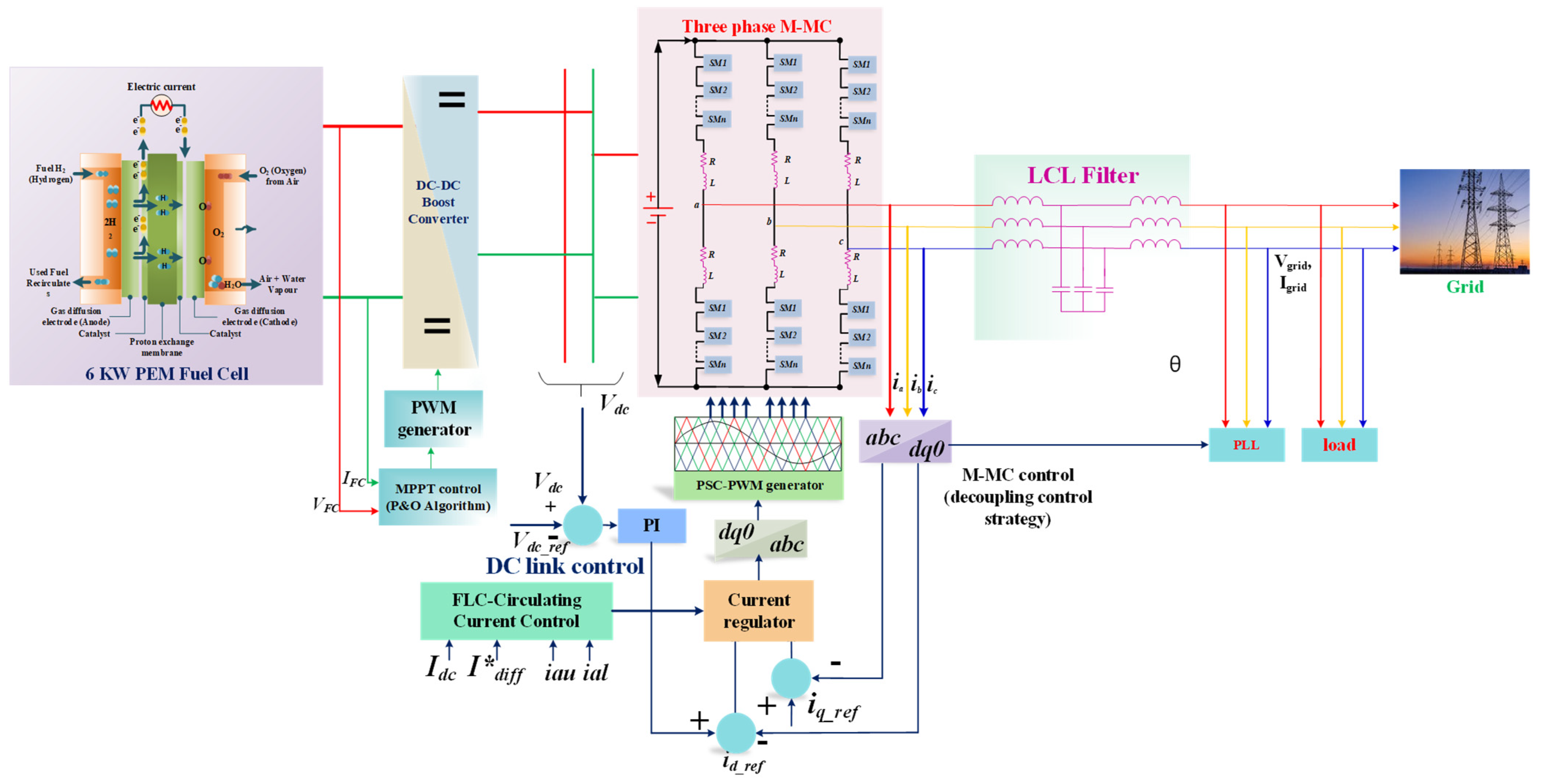
Section 2 specifies the system configuration of the three-phase grid-connected MMC-fed PEMFC, as well as the description and modelling of the PEMFC.
Section 3 deals with the overview of the MMC system and the implementation of the PSC-PWM technique of MMC, followed by MMC control in which the following factors were considered: (i) selecting the appropriate control variable for dc bus voltage, (ii) controlling the SM capacitor voltage, and (iii) controlling the circulating current control analysis. In the MMC, the proposed fuzzy logic controller was integrated into the circulating current control.
Section 4 depicts and discusses the real-time simulation results.
Section 5 contains the conclusion.
3. Assessment of the MMC System
3.1. Basic Circuit Operation of MMC
It employs a cascade connection of SMs to meet the optimum device voltage while providing a high multilevel output voltage waveform [
41,
42].
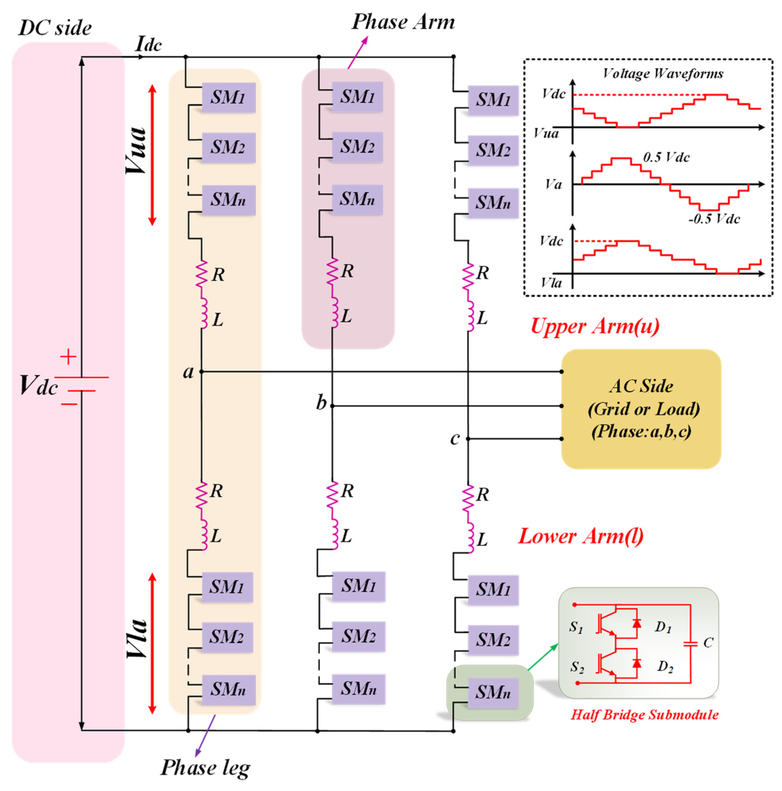
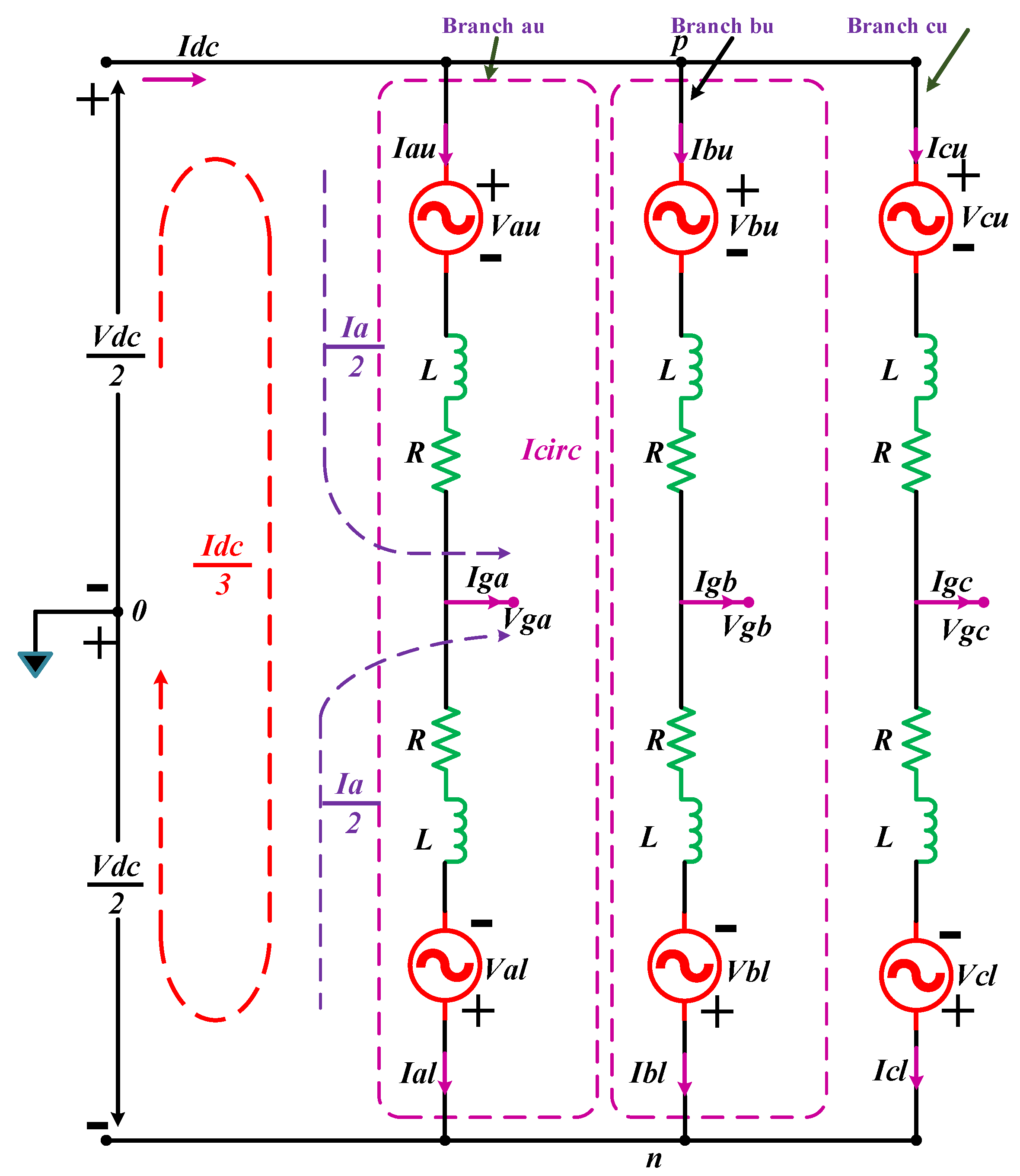
Figure 4 presents the grid-connected method of a three-phase MMC dc–ac converter. The SM is an element of the MMC which can be intended in a variety of forms using IGBT devices and dc capacitors [
43]. SMs are monitored to produce the desired ac voltages throughout the standard MMC operation [
44]. SM is a voltage source that can be operated. The half-bridge circuit or chopper cell is the most prevalent SM circuit topology [
42]. This is due to the huge energy consumption as well as the low number of parameters in the aforementioned SM.
The arm inductor is connected in series with each set of SMs to minimize the current caused by the input voltage difference between arms [
7,
45]. Accordingly, in the occurrence of a dc-side short circuit, the arm inductor neutralizes the leakage current by delivering low
[
46,
47].
The converter phase is referred to as a phase leg in this setup. Every phase leg is comprised of a split-up dc source with one upper arm ‘u’ (i.e., positive arm) and one lower arm ‘l’ (i.e., negative arm) linked between dc ports with a voltage . Every arm has an SM set (i.e., ‘N’ series connected, theoretically identical HB-SMs, an inductor (l), and resistor (r).
3.2. MMC Mathematical Modelling
MMC modelling can become complex, and simulation can take a while due to the large number of cells. To address this issue, several approaches for simplifying its model are suggested in the literature.
With levels, an MMC converter with n SMs per arm can accumulate a phase to the midpoint of the dc voltage. By expanding the number of SMs, the number of ac output levels can be accelerated.
The sum of the number of SMs in the ON state in each phase’s upper
and lower
arms represents the number of SMs per arm
n. There are
SMs in each arm.
During the activity of the MMC, the arm current moves through the SM capacitors, which charge and release the capacitors. The dc transport voltage
is similarly dispersed between all SMs. To ensure the proper process of the converter, the SM capacitor voltages should be directed to the reference value.
Considering the Kirchhoff’s voltage law of the circuit connecting points for both upper and lower arms (midpoint voltage of dc supply
positive arm
–midpoint of converter phase leg–midpoint voltage of dc supply) and (midpoint voltage of dc supply
–negative arm
–midpoint of converter phase leg–midpoint voltage of dc supply). The Equation is:
where
is
, which signifies the upper arm and lower arm voltages, respectively, and
is
, which shows the three-phase grid-side port voltages regarding the neutral state.
,
is (
which are the upper and lower arm currents, respectively,
is the arm inductor,
is the resistance, and
is the dc source voltage. When Kirchhoff’s current law is applied to the positive and negative connections of the MMC arm, the following result is obtained:
3.3. Implementation of Phase Shift Carrier PWM Technique in MMC
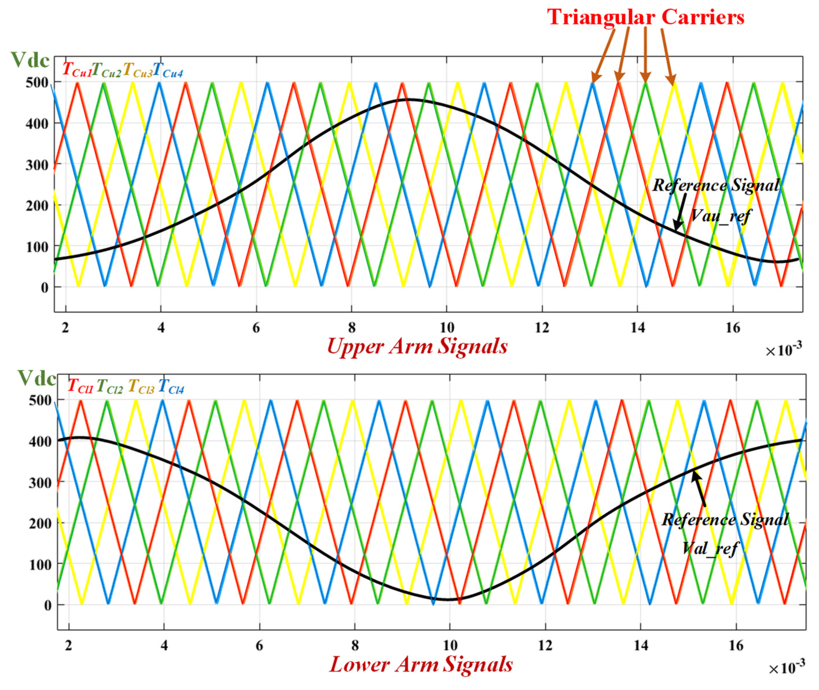
The triangular carrier signals can be placed horizontally or vertically within the linear modulation range. Phase-shifted carrier modulation is a modulation system in which identical triangular carrier signals are arranged horizontally (PSC-PWM) [
48]. Although there is a phase shift among adjacent triangular signals in PSC-PWM, all triangular signals have same frequency and peak-to-peak amplitude.
When generating a PSC modulation signal using MMC with SMs per arm (upper arm and lower arm), it requires triangular carriers (, for upper arm and , for the lower arm) with the frequency of and reference signals. Each SM has its exact reference signal and triangle carrier, ensuring that all SMs consume the identical switching frequency and semiconductor pressures are dispersed uniformly. The switching pulses of each SM are then created by associating the reference signal to the carrier wave for that SM.
These
triangular carrier signals have a phase shift
. The phase shift (
) in both the carrier angles is calculated as follows
Since this SMs of MMC are pulsed individually during PSC-PWM, voltage equalization of the capacitors can be accomplished by modifying the reference signal of each SM. For an amplitude modulation index ma = 0.95, an output frequency
, and an initial angle
, the phase-a and upper and lower arm reference modulation signals (
and
are created.
The evaluation of the reference modulating frequency to the carrier frequency has a consequence on the gating signals for upper and lower arm switches . Such gating pulses were sent to the components of each SM in phase-upper- , respectively.
As appears in
Figure 5, each upper and lower SM output voltage (
) and (
is equivalent to the gating pulses
and
, and their peak amount is equal to
. The lower arm voltage is equivalent to the number of SM output voltages. There are five voltage levels in the arm voltage, each with a
voltage step. The arm voltage can reach a maximum of
and a minimum of 0.
The ac and dc voltage buses of MMC can be obtained by deriving and incorporating the two Equations shown in Equation (2). By neglecting the voltage drop across the arm impedance, which is given as:
The output phase voltage does have positive and negative voltage levels, with a peak value of , as seen in Equation (18). With a step of , the output voltage has a maximum of voltage levels. seems to be the line-to-line voltage assessed over phases and b) and also has a maximum of 4N + 1= 17 voltage levels with a step of . Each SM is changed at a frequency of 625 Hz, which is the carrier frequency. MMC utilizes as its switching frequency.
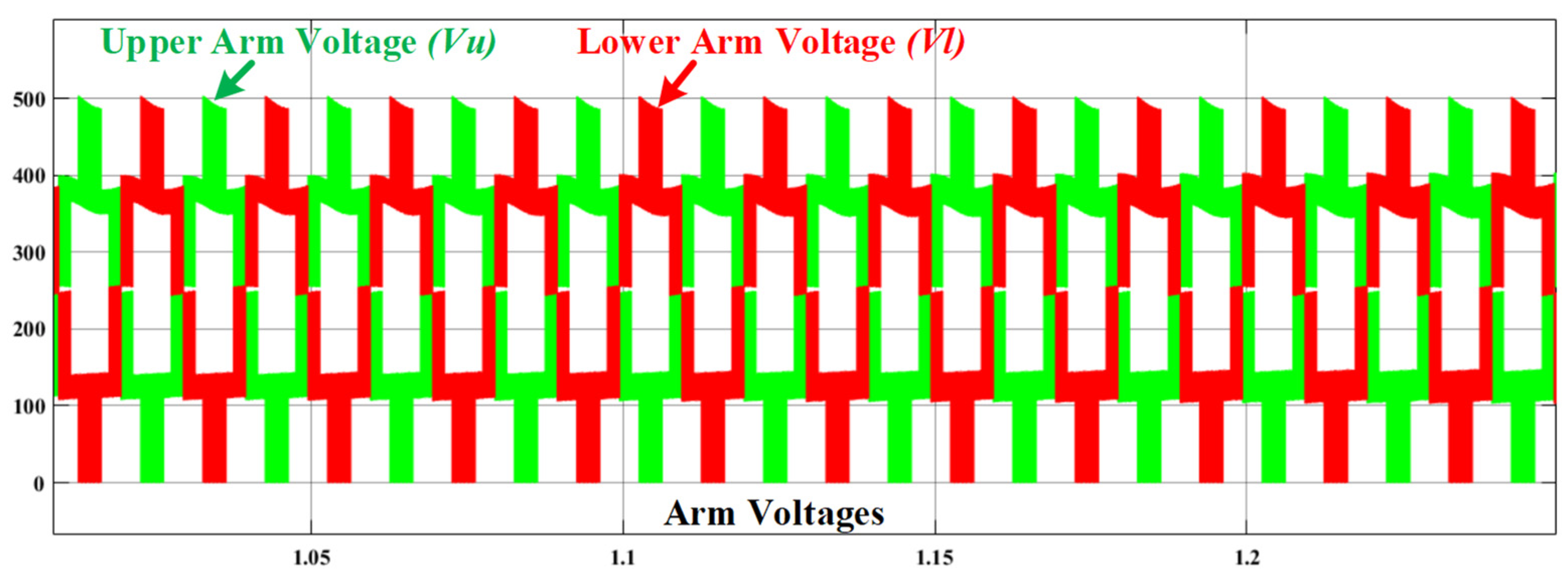
Each arm of the three-phase MMC is governed to produce unidirectional voltage which varies from zero to
, where
is the input dc voltage. Each arm is made up of both ac and dc elements. The arm voltages of phase
is depicted in
Figure 6. Under normal circumstances, it was shown that the three-phase MMC works well. Furthermore, the converter can generate significant waveforms. In the case of lower arms, the dc element corresponds to
, whereas the ac element corresponds to the connected output phase voltage, and in the case of upper arms, it corresponds to the antiphase of the connected output phase voltage.
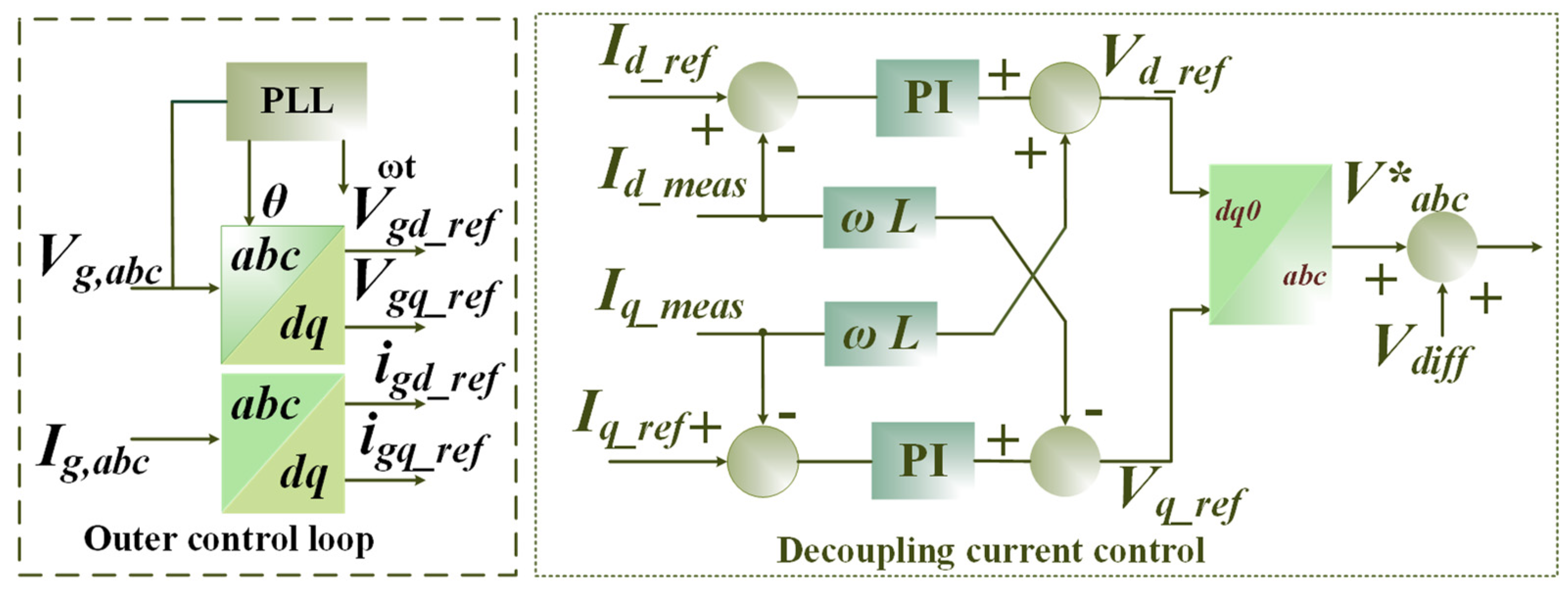
3.4. Control of MMC Grid Interface
As shown in
Figure 4, MMC component consists of dc voltage control, SM capacitor voltage, ac-side control, output currents, ac voltage control, and circulating current control. The converter’s outer control loop regulates the dc-link voltage, allowing for the stability of active and reactive power supplied toward the power circuit. The SM capacitor voltage method allows a voltage regulation control scheme as well as a leg voltage control. The voltage-balanced strategy assures that the SM capacitors start receiving the same voltage from inside the arm. The decoupled current control method is mainly accountable for voltage stability and current harmonic correction.
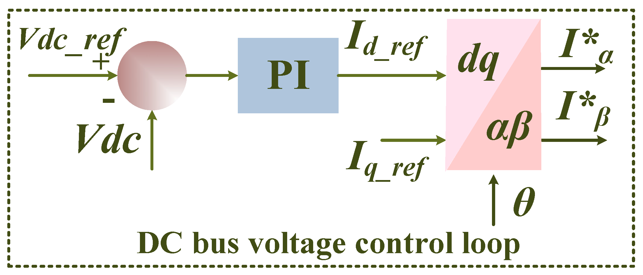
3.4.1. DC Bus Voltage Regulation
The dc-side control balances capacitor voltages while maintaining a constant dc-link voltage. To achieve this performance, cascaded control is used with two external voltage loops and one internal dc loop. The observed value
and the dc bus voltage reference
form one outside voltage loop. These signals are measured by a voltage regulator that is used to determine the dc-link current reference
which is used to compute each phase leg current reference.
Figure 7 depicts the dc bus voltage control loop.
3.4.2. AC-Side System Control
The ac-side control is aimed to accomplish overall SM capacitor voltage stability and unity power factor. To obtain this control, a cascade control with an SM voltage control loop and an inner control loop is used [
49].
Figure 8 depicts the inner control, which is derived on decoupling current control with
d-axis
and
q-axis
To estimate the value of
; this control loop refers to the SM voltage regulator
and the determined average value
. Current regulators have handled the
-axis current sources with their measured value of
and
. The inverse
transformation produces compensating voltage
from these output values. These voltages aid in stimulating the necessary three-phase leg input currents.
3.4.3. Voltage Regulation in SM Capacitors
By connecting more SMs in series in each arm, the effective voltage of the MMC might be enhanced. Since this SM has floating capacitors, the voltages must be maintained constant [
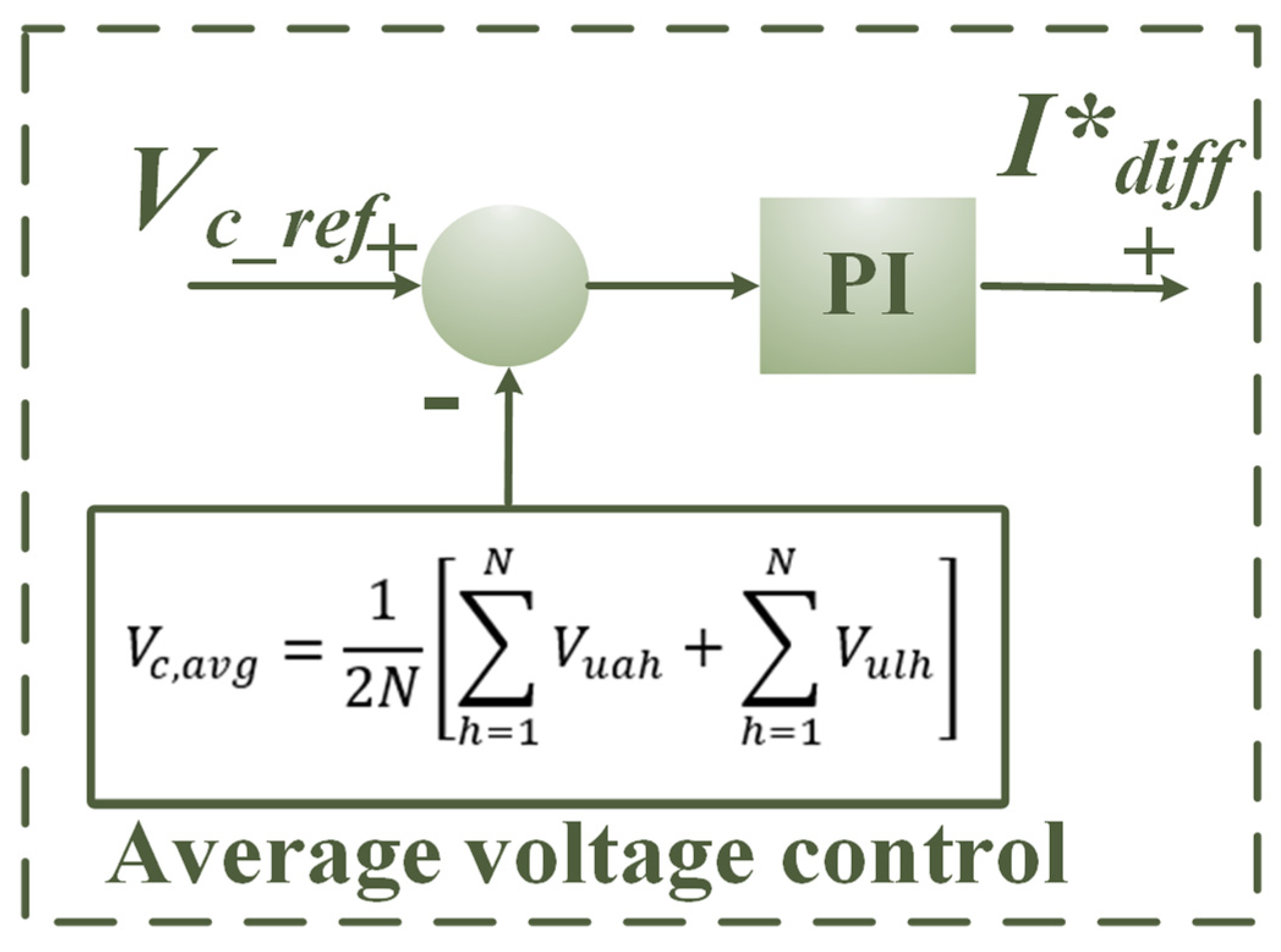
50]. The voltage of SM capacitors must be maintained in order to attain maximum current control, optimize output power quality, and maintain adequate and adjustable operation. The voltage balancing technique selects a specific number of SMs from an arm to produce the appropriate voltage level. As a result, the balancing method is also referred to as the SM selection procedure. The leg voltage control helps to regulate the average voltage of
SM capacitors at a steady state of
. The average voltage measured on each leg is provided by:
where
,
are the SM capacitor voltages in the upper arm and lower arm of the converter leg, respectively. The average voltage control is as presented in
Figure 9.
To control the entire capacitor voltage in each arm, an outer loop with a proportional-integral (PI) controller is used. The PI controller
regulates the number of capacitor voltages in each arm to match the dc bus voltage. A proportional-integral (PI) controller regulates the overall capacitor voltage in each arm via an outside loop. The PI controller
modulates the total amount of all capacitor voltages in an arm to equal the dc link voltage, which results in:
3.4.4. Analysis of Circulating Current Control in MMC
There is a CC in each phase of the MMC which does not present at the converter’s output. The CC is made up of both dc and ac components. The simplest way is to regard each arm’s power cells as a separate equal voltage source, as shown in
Figure 10.
The converter’s component involves the dc component. A current (upper
and lower
) is circulated proportionally to half the phase current
in each of the arms.
The three-phase side terminal currents are characterized by
. The CCs in phase units
a,
b and
c are
, defined as:
The dc is dispersed equally across the three converter legs, whereas the ac is split equally between the two sides. The CC is the same on both arms of the leg since it flows inside the converter and is represented as:
The above Equation demonstrates that the arm voltages have a substantial impact on the MMC circuit’s input ac-side and output dc-side voltages. The capacitor voltages of the SMs oscillate about their average value since there are no constant voltage sources. As a result, the instantaneous total of all inserted capacitor voltages in all phases is not equal, causing the phases to circulate current. A dc component plus a prominent second harmonic component make up the circulating current. As illustrated in
Figure 5, the arm currents are made up of two components: circulating current and fundamental frequency current. The currents in the arms can be represented as follows.
where,
is the power factor angle,
is the ac-side current amplitude, and
and
are the amplitude and phase angle of the second harmonic CC, respectively. The magnitudes of higher-order components are significantly small. By connecting the input power
and output power
of MMC,
can be expressed as in (6) in terms of
,
, and modulation index
.
The conventional MMC controllers aim to control the second harmonic CC found in arm currents [
51,
52]. When the second harmonic CC is eliminated by such controllers, as presented in (23) and (24), the arm current is a dc-biased ac, as shown in (7). The peak of the upper and lower arm currents is a function of the power factor (PF) as can be observed from (7). Considering
, when the system is operating at zero PF (ZPF), from (24) and (25), the arm current swings between
and
. Because of the greater peak, the semiconductors must be rated higher as well. It is recommended to employ a fuzzy logic controller, which is covered in
Section 4, to gain additional flexibility in the design of controller gains.
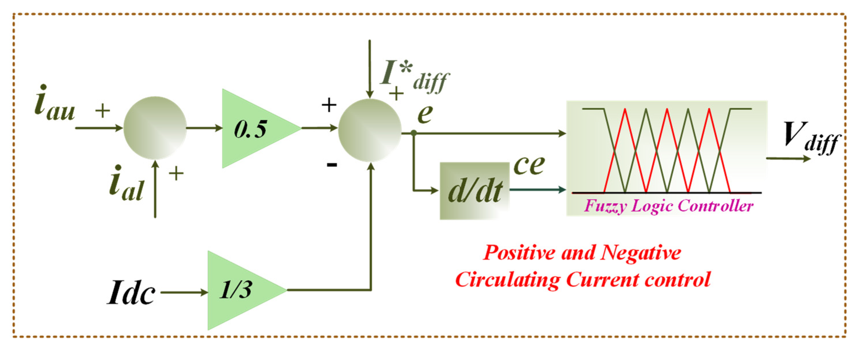
4. Proposed Fuzzy Logic Controller Integrated to Circulating Current in MMC
An MMC generates CCs, which circulate in between the arms of the converter but not outside of them. These currents are determined using the variable voltage between the converter legs of upper and lower arms. The capacitor voltage fluctuation is a single source of CC that has a frequency double that of the output. ac output voltages and currents are influenced by the CC. The CC does not disturb the ac output voltages and currents. However, inadequate circulating current control increases the arm current peak/RMS value, which subsequently affects the SM capacitor voltage’s ripple, device power losses, and device rating.
To control the current control voltage source, the three-phase circulating current suppression is proposed.
Figure 11 depicts the proposed fuzzy logic control of CC in an MMC. The fuzzy logic is required to consider every element of CCs under the unstable voltage. The controller operates directly on the CC by determining the number of SMs within the arm to drive it to its reference value. It avoids the requirement for extra voltage reference injections into the converter’s output voltage reference or additional control loops. The fuzzy controller is the optimum solution for decision making. For nonlinear loads or large industrial applications, fuzzy provides more precision.
The FLCs are advanced expert systems. To solve a problem, an FLC uses a knowledge base described in terms of fuzzy inference rules and a fuzzy inference engine [
53]. A fuzzy system is defined by a set of linguistic description rules based on expert knowledge in an FLC. Expert knowledge is often described as IF (a set of criteria are met) THEN (a set of consequences can be inferred) [
54].
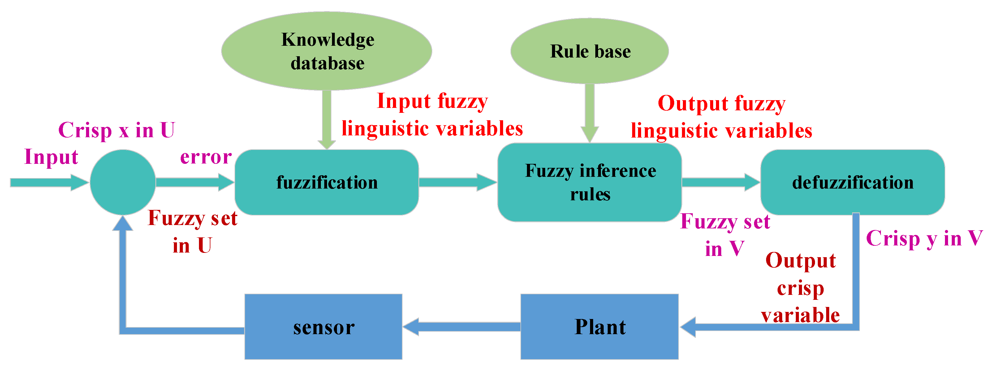
A fuzzy controller works by repeating the procedures described in
Figure 12: all variables representing the relevant circumstances of the controller process are measured (inputs). Fuzzification [
53] is the process of converting measurements into suitable fuzzy sets in order to communicate measurement uncertainty. The fuzzified measurements are then utilized by the inference engine to assess the control rules given in the fuzzy rule base. Based on the universe of potential actions, this assessment generates a fuzzy set (or numerous fuzzy sets). This output fuzzy set is subsequently reduced to a single (crisp) value (or a vector of values). Defuzzification is the final step. The fuzzy controller’s actions are described by the defuzzified values. Various fuzzy rules have different effects for fuzzy inference [
55]: The Takagi–Sugeno fuzzy model and the Mamdani fuzzy inference system (TS method). The Mamdani fuzzy logic was used in this study to reduce CC in the MMC.
Rules: it incorporates all expert rules as well as the IF-THEN condition. Various effective strategies for creating and tweaking fuzzy controllers to guide the decision-making process are provided by fuzzy theory [
56]. Typically, this progression lowers the number of fuzzy rules as well. The following are examples of fuzzy rules.
, and
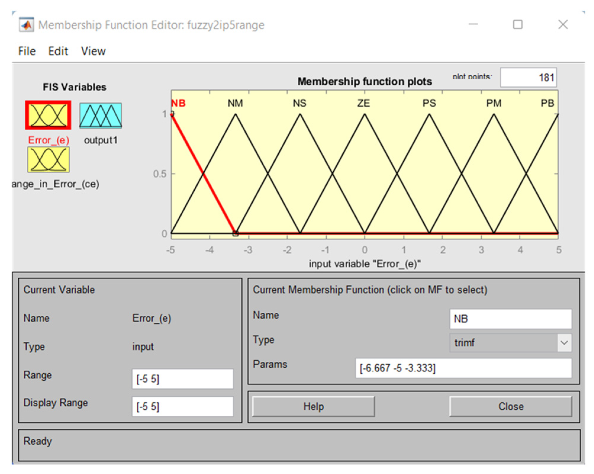
are the fuzzy subsets of their discourse universe. Every universe of discourse was divided into seven sections into fuzzy subsets: big positive (BP), medium positive (MP), small positive (SP), zero (ZE), small negative (SN), medium negative (MN), and big negative (BN). The standardized values of
and
are [–1,1], whereas the range of m n is [−1,1]. For every combination of mistake
and change in error, a maximum of 49 rules were applied
.
Table 2 explains how to construct a rule basis.
In the inference result, each rule contains two components. The precise rule of the weighting function
Wi and also the rate of membership of the modulated signal
, may be expressed according to the rule as:
Fuzzifier: in this procedure, the input or crisps number is turned into fuzzy sets. Sensors compute it and communicate it to the control system for processing. The degree of correlation among fuzzy input fields is defined by the inference engine or intelligence. It decides which rules will be followed. It involves considering the fire rules and putting them together with the control actions.
Defuzzifier: the process of converting a fuzzy component into a crisp member or reducing a fuzzy set to a crisp set [
56].
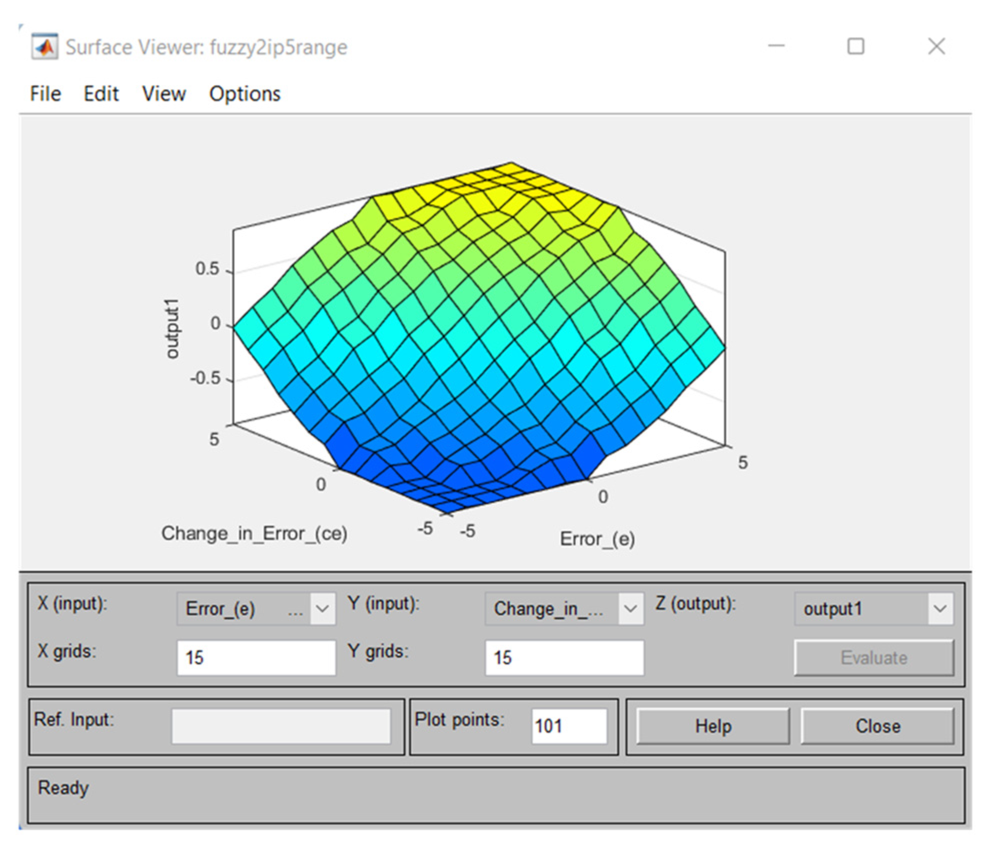
The developed fuzzy controller membership function is shown in
Figure 13. In this scenario, the FLC was tweaked by input values ranging from
, dual inputs
, and a single output value to construct membership functions.
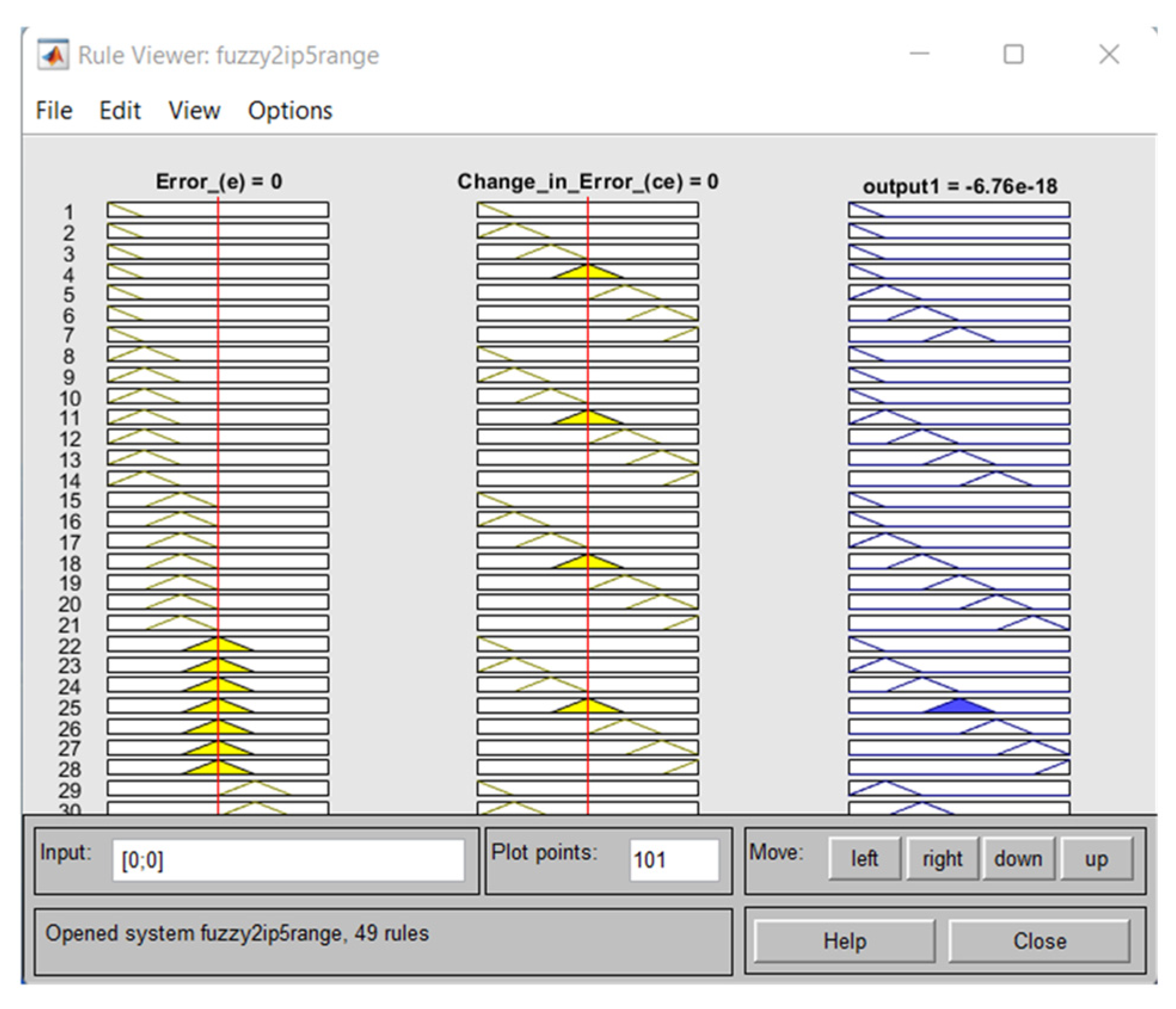
From the complete input and output values, the seven membership functions were examined, and a total of 49 rules were created particularly for the fuzzy controller.
Figure 14 depicts the developed fuzzy controller rules, whereas
Figure 15 depicts the appropriate surface plot of the fuzzy layout.
5. Real-Time HIL Results and Discussion
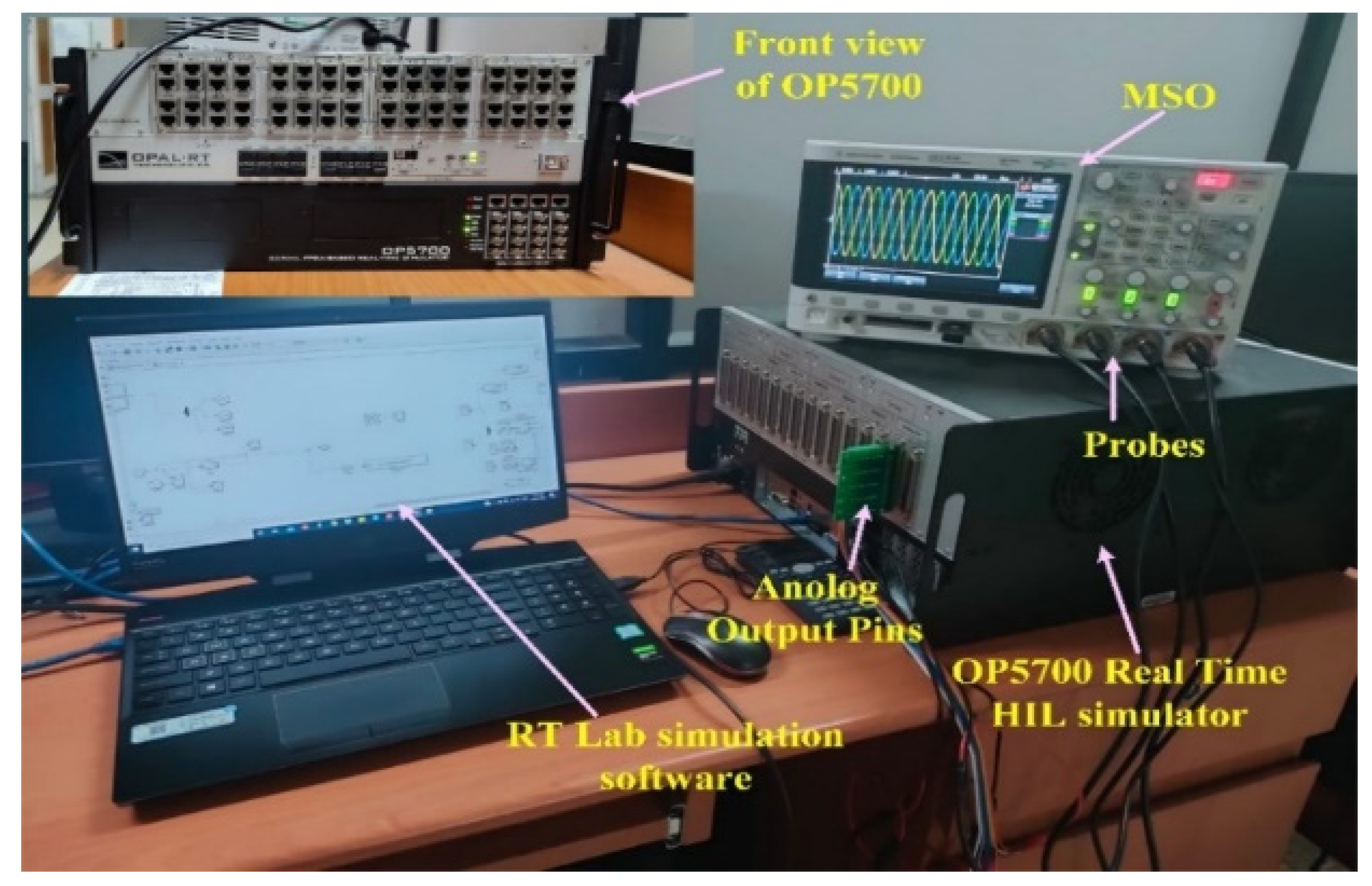
The conclusive architecture was implemented in MATLAB/SIMULINK and tested using the real-time simulation field for system process and control of the MMC.
Figure 16 depicts the HIL configuration. The entire system referring to
Figure 1 is a built-in RT lab simulation which was dumped into the OP-5700 real-time HIL simulator to validate system performance and the validity of the PSC-PWM of MMC as well as the proposed fuzzy logic for circulating current suppression in the MMC. The MMC system control parameter values are tabulated in
Table 3. On the other hand, PEMFCs have a low operating temperature of around 80 °C (353.15 K). A low-temperature operation enables them to start faster (because of a reduced warm-up time) and reduces stress on the components of the system, resulting in increased dependability.
The amount of power produced by a fuel cell method is determined by water and heat management, pressure control, hydrogen, and oxygen flow. One of the fundamental process issues is reactant utilization, which is connected to the fuel cell stack current. The control system must regulate the hydrogen flow rate when a load is attached to a fuel cell system to prevent FC voltage depreciation. The power produced by the PEMFC temperature was 289 K in this scenario. In this regard, the PEMFC generated 6 kW of power, 45 V of fuel stack voltage, and 133.3 A of current was generated at temperature T = 332 K.
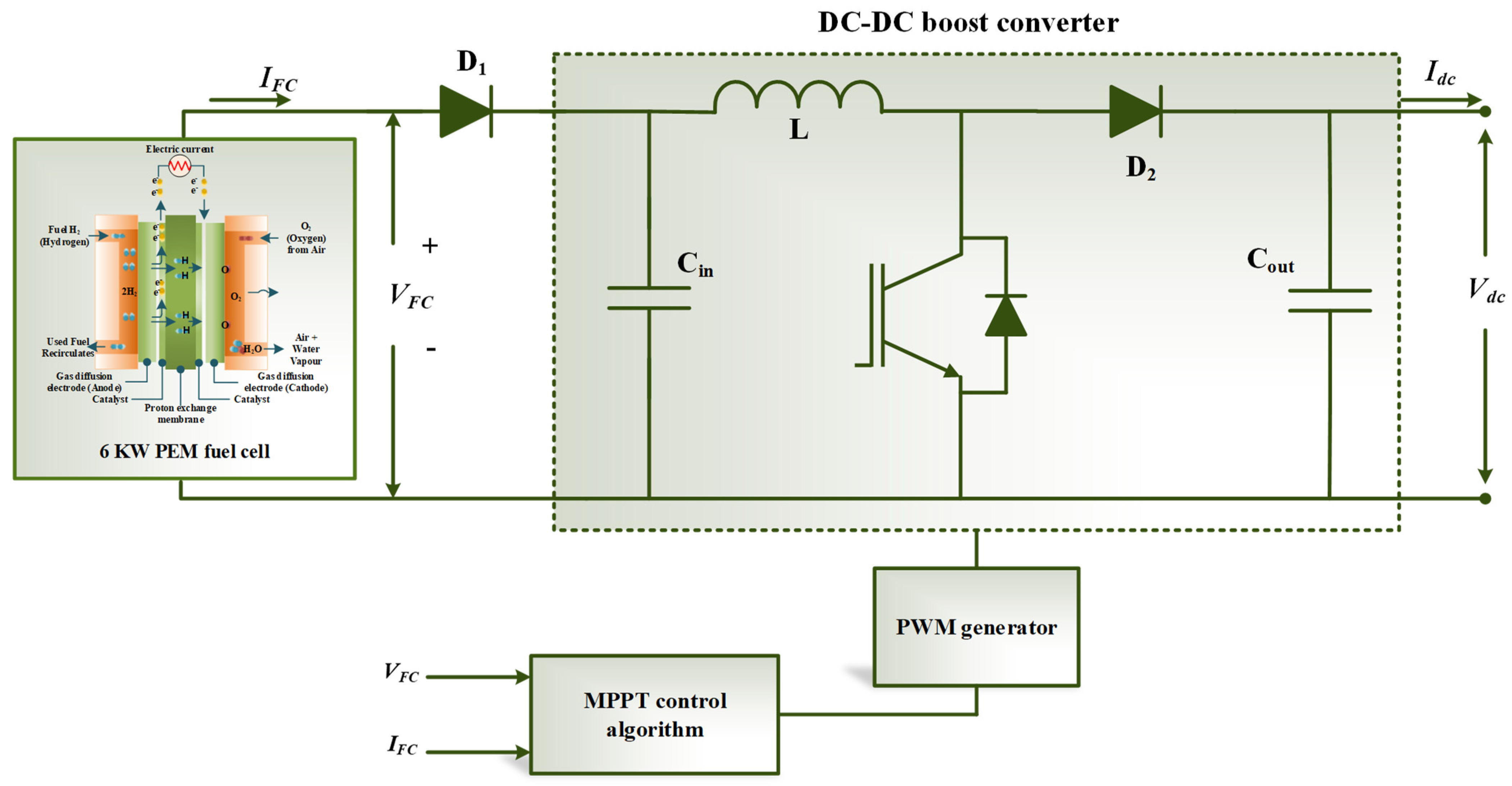
The boost converter regulates and controls the fuel cell’s output power. The boost converter accepts the fuel cell’s unregulated output voltage. Despite variations in hydrogen flow rate, load, or fuel cell operational parameters, the PI controller changes the MPPT duty ratio of the converter to deliver the appropriate output voltage. The MPPT technique is only used for tracking the maximum power attained via the fuel cell that may indirectly aid in enhancing the system performance. The PEMFC boost converter provides the highest output voltage required to maintain a constant dc bus voltage of 500 V. The produced dc-link power was 6kW and the dc-link current was 12 A at T = 298 K.
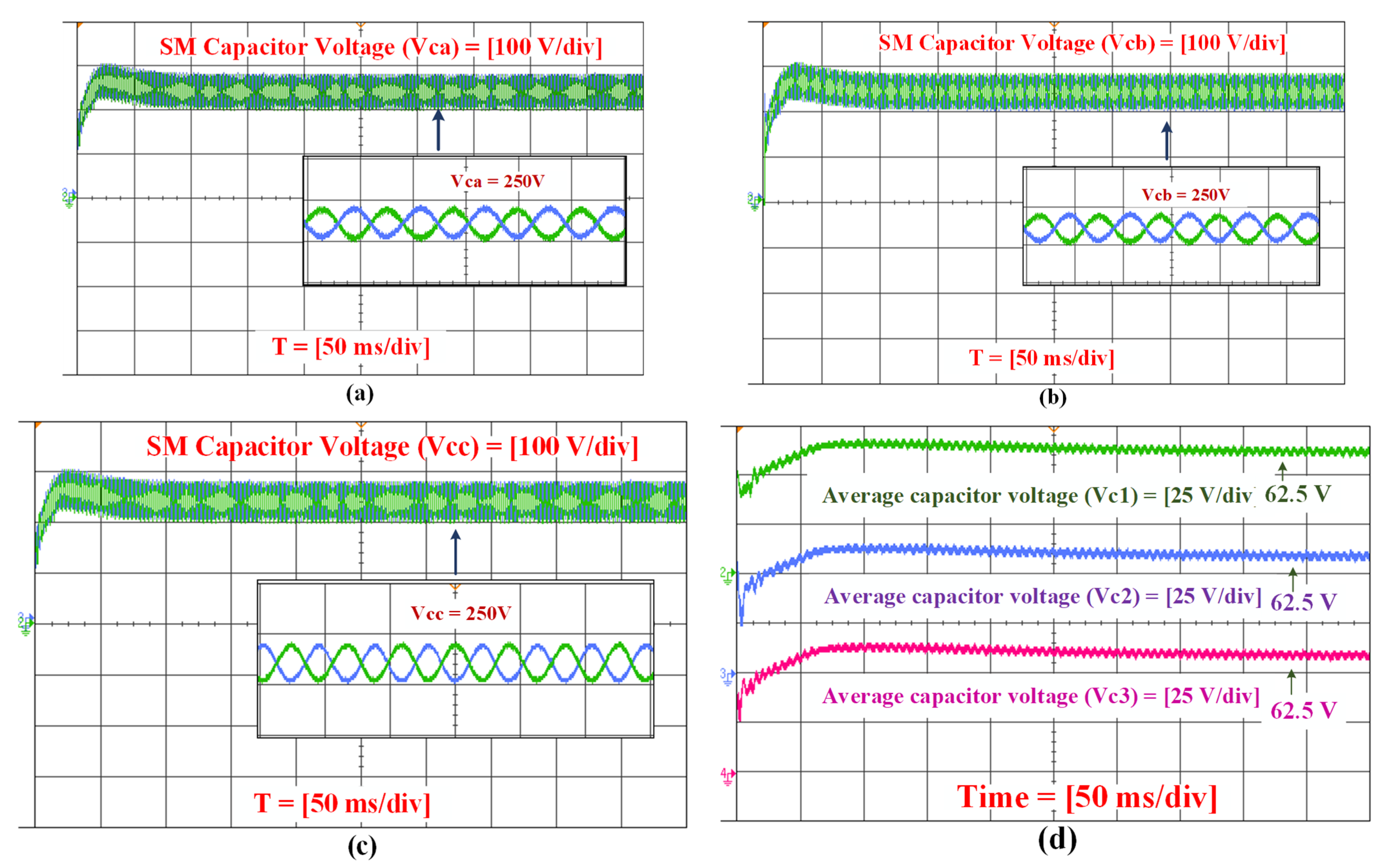
Impacting voltage of an SM capacitor: the upper and lower arms of the SM capacitor voltage on an individual basis are depicted in
Figure 17a–c. As a result, with a peak value of
, the output phase voltage contained positive and negative voltage levels. The output voltage had a total
voltage levels with a step of
. By balancing the voltages of individual SM capacitors, a sorting method for maintaining their voltages in the MMC was established. These sorting approaches might produce a tremendously asymmetrical switching frequency among the SMs, resulting in higher converter losses. The average capacitor voltage regulator oversees confirming that the incoming dc is distributed evenly across the MMC leg and that the excess voltage of every leg’s SM capacitor equals the average voltage value. In this regard, the line-to-line voltage
was measured across phase (
and
b) and had a total of 4
N + 1= 17 voltage levels with a step of
.
Figure 17d depicts the average SM capacitor voltage for each phase. The voltages of SM capacitors deviate from their stable values when a load is connected to the grid. Voltage fluctuations were reduced dramatically, and voltages were at an acceptable level. The SM capacitor voltages were balanced, with a peak voltage ripple of 62.5 V at the base frequency.
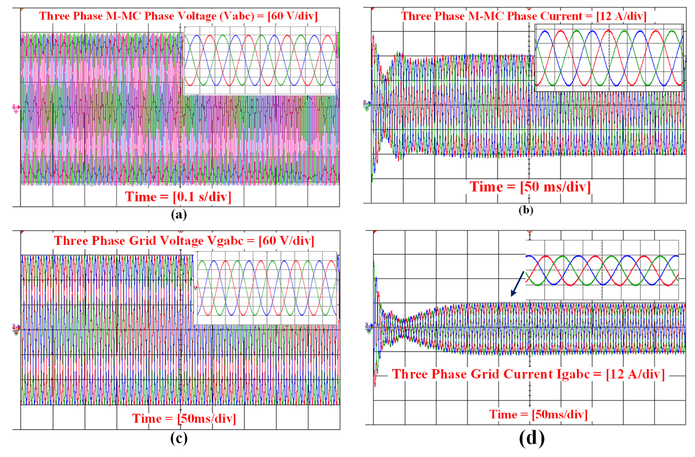
Figure 18a,b shows the output voltage and current for three-phase MMCs, respectively. A grid-connected PEMFC system of 6 kW was tested. For both tests, the dc-side load was maintained constant at 5 kW (dc constant load and grid-connected). The MMC transformed the dc power provided by the PEMFC with an operating voltage of 45 V to alternating current power. The power acquired through the LCL filter (input from MMC) was well-controlled, and the capacitor sizing and structure of the
frame loops allowed us to prevent harmonics that may disrupt the functioning of the producing power system. By using the proper current control technique, voltage waveforms were effectively smoothed. In this case, the PI regulator was utilized to switch the current drift by utilizing the response current from the load.
Figure 18c,d demonstrates that the grid voltage and current of MMC were in phase, resulting in an injected power with a unity power factor. Using the systematic solution for a PSC-PWM-based MMC structure, it was identified that the THD value for MMC phase voltage was 1.89% and the grid current was 2.30%.
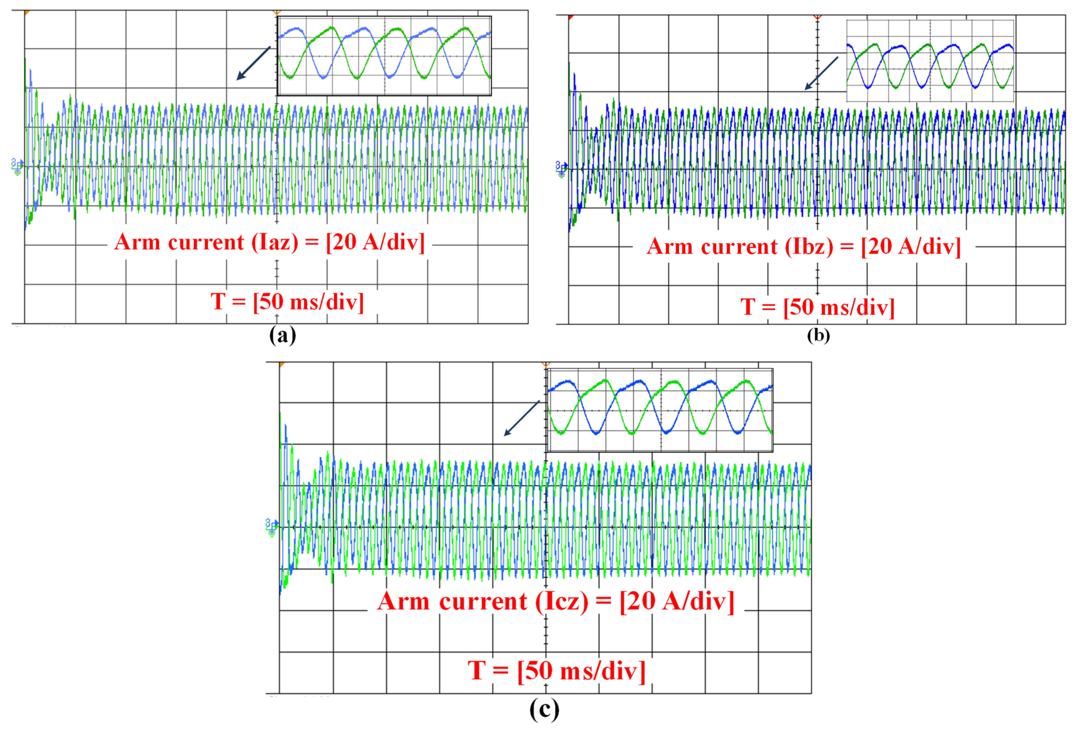
MMC’s arm currents and circulating current without controller: to compensate for the SM capacitor voltage fluctuation, the CC control in MMC contributes the common mode component to the arm voltages.
Figure 19a–c depicts currents for each phase
of the upper and lower arms, respectively, which mostly comprised the fundamental component without harmonics. Because the circulating current contained both dc and ac elements in the same flow, the arm currents were distorted. The dc-side current was distributed evenly throughout the three phases, which improved the power balance in capacitors. The dc component of the arm current must be included since it depicts the active power transfer between the alternating current and direct current sides. CC can be regulated more still by utilizing the proposed model, which is explained numerically in the following section.
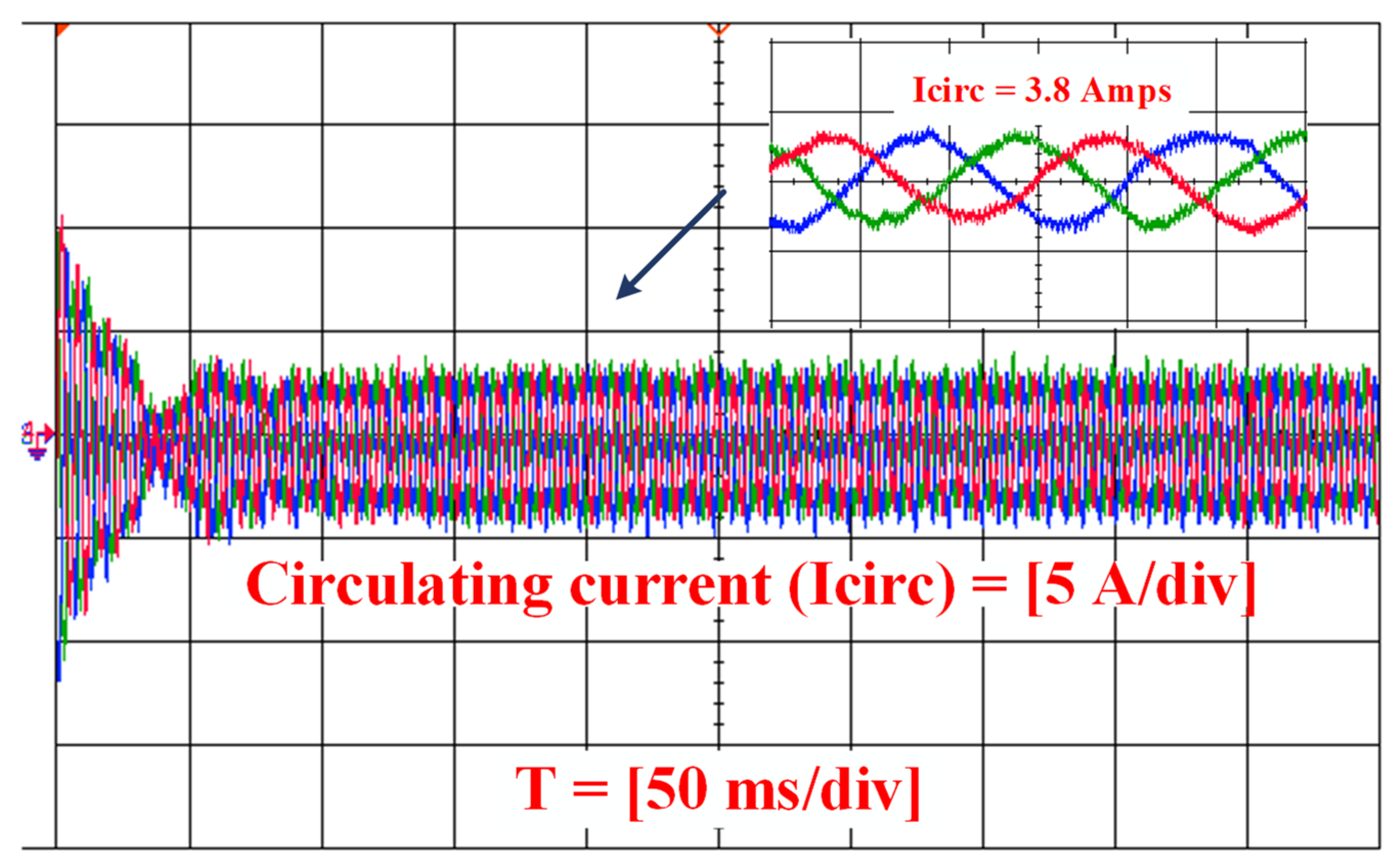
From the conventional method [
57], the output of the CC without regulator in the MMC was 4 A and the peak value of the CC using synchronous
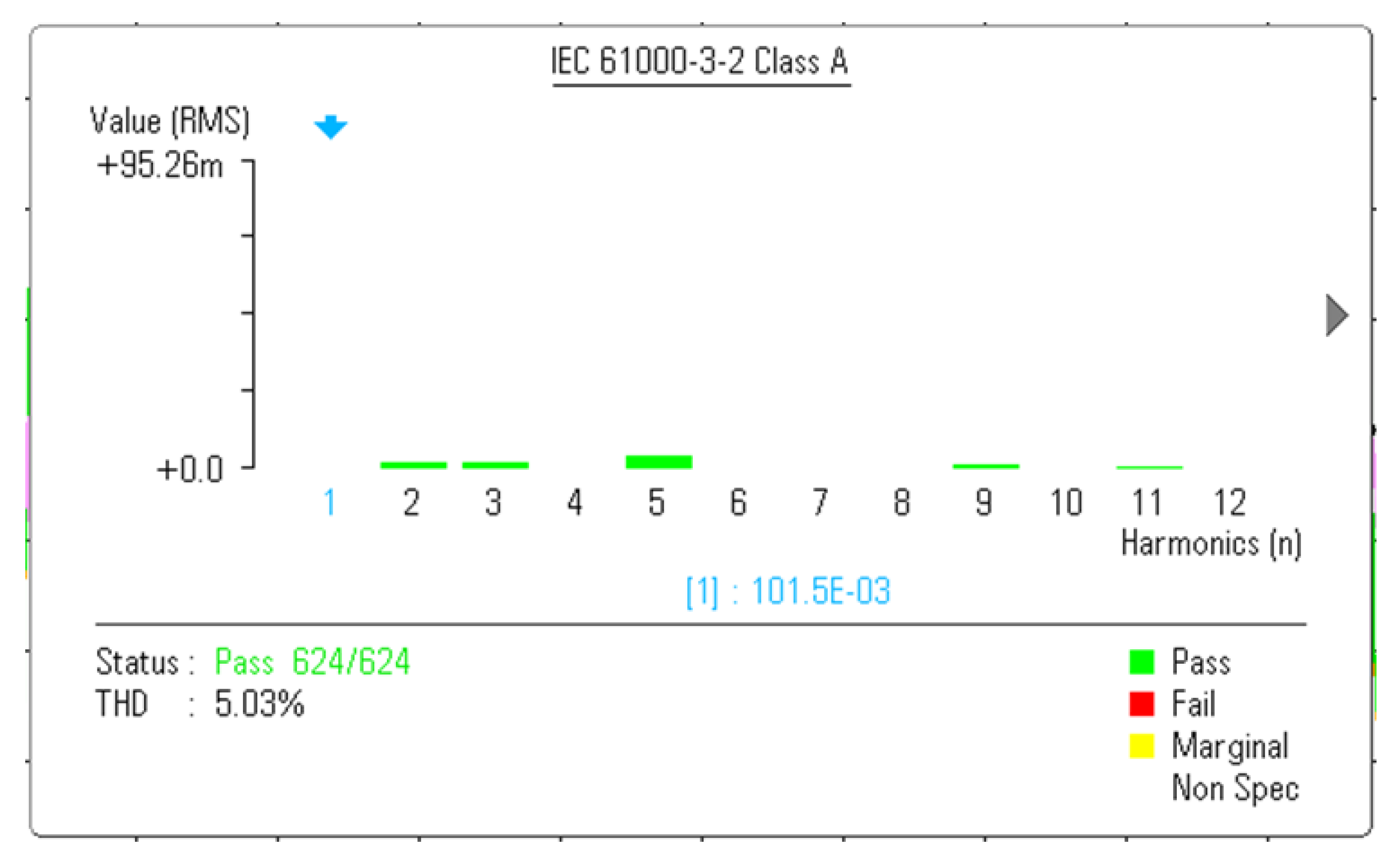
frame was approximately 3 A. In this regard, a PSC-PWM scheme for MMC was proposed in this work, and it was noticed that the output voltage showed five voltage levels with low harmonic elimination. As a result, the peak value of the second-order harmonic of the CC without controller was approximately 3.8 A, which is shown in
Figure 20, and the corresponding FFT analysis with THD was 5.03%, as shown in
Figure 21. It is significant to note that the obtained peak current was nearly half the peak arm current. Circulating current had no effect on the ac output voltages and currents. However, poor circulating current regulation raised the peak/RMS value of the arm current, increasing device rating, device power losses, and ripple in SM capacitor voltages [
58,
59]. By properly sizing the arm inductors, the magnitude of the CCs can be reduced to an extent [
60]. However, a closed-loop control method is required to eliminate the CCs completely. As compared to convention methodologies, the circulating current can be regulated more still by utilizing the proposed model with an MMC, which is explained numerically in the following section.
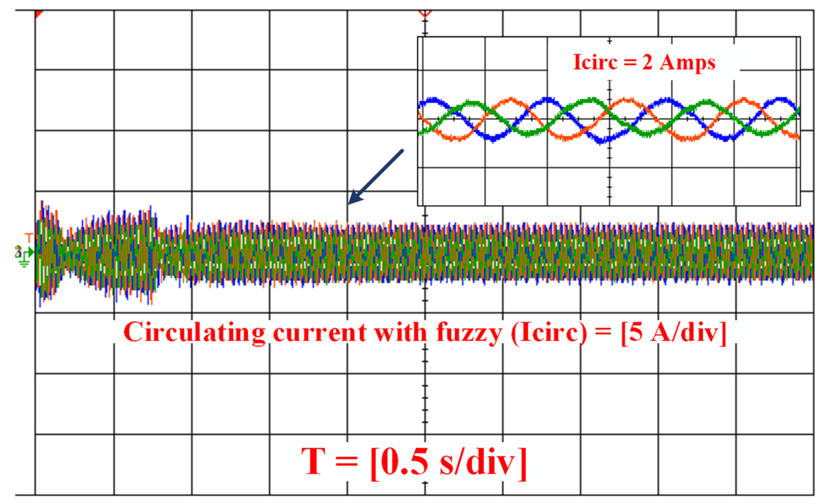
Proposed fuzzy logic circulating current: the second-order harmonic dominates the CC in MMC, which may be greatly decreased using CC suppression control. The proposed method suppresses the magnitude of CC while reducing the ripple in capacitor voltages.
Figure 22 shows the proposed model of CC in MMC and corresponding FFT analysis is as shown in
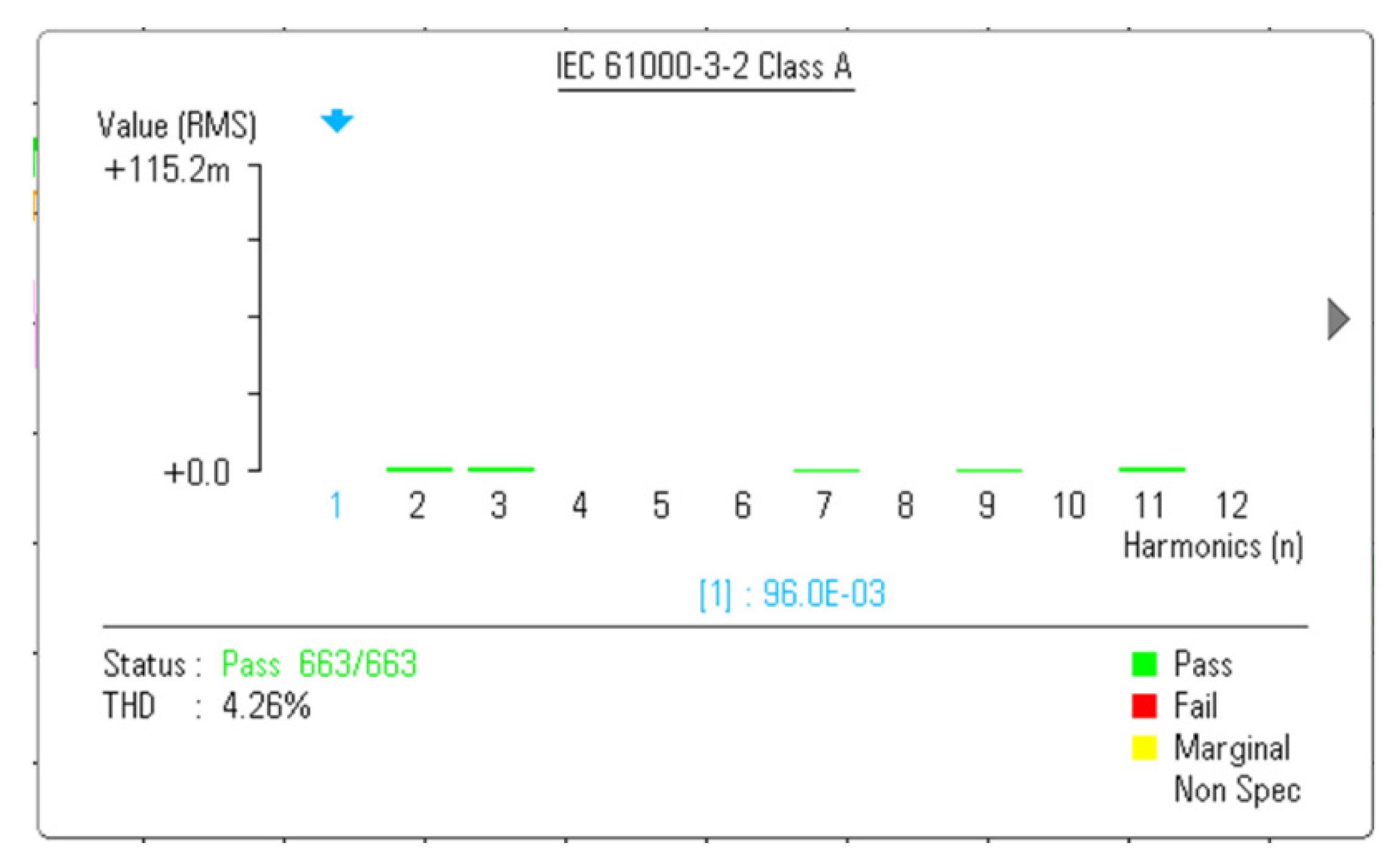
Figure 23. As shown in the waveform, the circulating current mainly contained the dc component, and the second-order harmonics in CC was almost eliminated. The proposed method suppressed the magnitude of the CC to a minimum value. As a result, the proposed controller enhanced an MMC’s efficiency and lifespan. Furthermore, without a supplementary controller, it prevented the second harmonic current from flowing into the dc connection. From the proposed method, the output of the circulating current was approximately 2 A and corresponding FFT analysis with THD was 4.26%. As the distortion is reduced, a better (sine wave) sinusoidal arm current waveform can be created using this approach.
For the given proposed system, the THD was reduced to 4.26% and the circulating current was minimized to 2 amps. By utilizing the proposed system, the THD value was achieved to some extent, only irrespective of the fuzzy range of variation, and as a future work, the peak value of circulating current and THD value can be reduced further to achieve better efficiency by utilizing new control technique.
As an application-oriented topology, it is predictable that the MMC will be guided to be more customized and well-adapted in the specific application area in terms of power transmission and quality improvement. The fuzzy logic method can deal with multiple constraints in a single cost function and provide a fast dynamic response and robustness against parameter variation and external disturbance. The fuzzy logic control was employed as the primary controller to control the output and circulating currents. Meanwhile, the SM capacitor voltage balancing was applied as the secondary controller to equalize the SM voltage within the arm.
The MMC system offers many advantages over conventional voltage source converters and in dc power transmission, micro grid, or renewable energy applications. MMC’s distinctive topology provides a wide variety of new features, necessitating the use of a sophisticated controller for extra control requirements. Over the course of two decades, OPAL-RT has grown into a major real-time solution provider for testing and validating new MMC’s sophisticated controls within an HIL platform. OPAL-RT provides rapid control prototyping technologies to help engineers develop and test new control algorithms, improving technical solutions through the facility of an MMC system.


