Abstract
Concentrated solar power is capable of providing high-temperature process streams to different applications. One promising application is the high-temperature electrolysis process demanding steam and air above 800 °C. To overcome the intermittence of solar energy, energy storage is required. Currently, thermal energy at such temperatures can be stored predominately as sensible heat in packed beds. However, such storage suffers from a loss of usable storage capacity after several cycles. To improve such storage, a one-dimensional packed bed thermal energy storage model using air as a heat transfer medium is set up and used to investigate and quantify the benefit of the incorporation of different thermochemical materials from the class of perovskites. Perovskites undergo a non-stoichiometric reaction extension which offers the utilization of thermochemical heat over a larger temperature range. Three different perovskites were considered: SrFeO3, CaMnO3 and Ca0.8Sr0.2MnO3. In total, 15 vol% of sensible energy storage has been replaced by one perovskite and different positions of the reactive material are analyzed. The effect of reactive heat on storage performance and thermal degradation over 15 consecutive charging and discharging cycles is studied. Based on the selected variation and reactive material, storage capacity and useful energy capacity are increased. The partial replacement close to the cold inlet/outlet of the storage system can increase the overall storage capacity by 10.42%. To fully utilize the advantages of thermochemical material, suitable operation conditions and a fitting placement of the material are vital.
1. Introduction
The reduction of greenhouse gas emissions is one of the biggest challenges in today’s societies. The production of synthetic fuels or other green hydrogen-based chemicals using renewable energy is essential to decarbonize several industrial and transportation sectors which cannot be decarbonized using electricity only. For example, road transportation alone accounted for almost 72% of greenhouse gas emissions of the transport sector in 2017 [1]. Additionally, heavy industries alone account for 25% of all energy and process CO2 emissions of which 70% take place in steel, cement and chemicals [2]. In the heavy industry and aviation sectors, green hydrogen is one important consumable for achieving net zero emissions by 2050 [2,3]. Therefore, hydrogen production with concentrated solar power (CSP) in the Earth’s sunbelt region is one promising method for achieving this goal [4].
For this study, high-temperature electrolysis (HTE) coupled with a concentrated solar process has been analyzed. It has been shown that the high-temperature heat supply by concentrated solar thermal (CST) process is promising for resource-efficient hydrogen production [5,6,7,8,9,10,11,12]. Furthermore, the supply of high-temperature heat promises the highest electrical efficiencies among the available electrolysis technologies [13]. The provision of high-temperature heat using a CST system with an electrical energy supply from photovoltaic (PV) results in H2 production costs (LCOH) below 5 USD/kg H2 [7]. In other scenarios using alkaline electrolysis and CSP/PV as electrical energy sources, H2 costs can get as low as 3.09 USD/kg with about 4000 full load hours in a 2030 scenario and 3.3 USD/kg at almost 7000 h [14]. For more efficient H2 production, the use of HTE in a CST process is promising lower production costs due to the very high efficiency of the HTE [15]. CST is capable of providing the needed process stream at high temperatures to the HTE and has been investigated for this study. State-of-the-art HTE uses yttria-stabilized zirconia as an oxide ion conductor and is operated in the range of 700–900 °C [16]. Stacks based on these solid oxide cells can be operated at degradation rates of +0.5%/1000 h [17]. Current research focuses on steam electrolysis operated at temperatures as low as 350–600 °C [6,16,18]. However, higher temperatures are still offering the lowest electrical energy consumption as a larger amount of energy to spilt H2O into H2 and O2 is provided as heat and thermoneutral operation with highest electrical efficiency is possible. Furthermore, considering the state-of-the-art electrolysis stack in process evaluation excels the maturity of such processes.
The efficiency and sustainability of processes powered by fluctuating resources such as solar demand require cost-efficient energy storage capabilities. The potential of a storage system in a CSP application is closely related to the solar power share of the process [19,20]. New solar-powered processes are especially affected by a reliable storage system. Cost-efficient thermal energy storage (TES) can decrease overall system costs. CSP systems are mostly using molten salt as a heat transfer fluid (HTF) and storage media. Molten salt processes can be operated at temperatures up to 565 °C [21]. However, storing heat at temperatures above 600 °C, air is suitable as an HTF, and solids and their specific heat capacity as filler material have been of major interest in TES applications in recent years [19,22]. Typically, a solid material is considered with sensible thermal energy storage characteristics. The material is in particle shape and is loosely packed, thus achieving a natural void fraction ψ of 30–40% empty volume. The void fraction allows a stream flow through the bed and a direct heat exchange between filler material and HTF. Thus, due to the storage filler, there is a flow through porous media which can also be described as a two-phase system (i.e., solid and gas phase). However, this kind of TES is affected by thermal degradation due to thermal diffusion in a cycling operation [23,24]. This degradation decreases the volumetric storage capacity resulting in a larger TES size and investment costs increasing. One option to mitigate thermal degradation is the use of phase change materials. Cascading the storage with latent phase change material has been investigated for potential thermocline improvement [25,26,27,28,29,30]. For this, phase change material is located at the inlet/outlet boundaries of the TES and the phase change of the selected material shall takes place at temperatures close to the hot/cold inlet/outlet temperature of the TES. Thus, the thermocline gradient becomes steeper and the useful storage capacity is increased. However, the latent phase change material requires suitable encapsulation and suffers from low thermal conductivity in a solid state [19]. Another option for improving cycling behavior is the active thermal management of the TES system [31,32,33]. Here, the HTF is injected into or released from certain sections of the TES to control the thermocline. While the active thermal management is a promising technology for increasing the useful volumetric heat capacity, it requires a more complex system. Additional sensors, valves, controllers and actuators are needed to adopt this technology. For the analysis of TES operation behavior, different models can be used. Esence et al. [22] listed different types of models. These models are described by the dimensions and phases considered for the heat transfer evaluations (e.g., 1D–1P, 1D–2P, 2D–2P, etc. where D stands for dimension and P for phase). Cascetta et al. [34] showed that the difference in the solution from 1D to 2D in a two phase representation can be neglected for the centerline thermocline along the flow direction. Thus, a storage capacity estimation is achieved with low computational costs. Furthermore, detailed process and storage simulation for techno-economic analysis is possible with lower computational costs. In this study, a 1D–2P model is developed to investigate the use of thermochemical materials as another option to mitigate thermal degradation effects.
For the efficient solar heat-supported HTE operation, a detailed analysis of the utilization of thermochemical reactive material as packed bed TES filler is carried out. As volumetric storage capacity increases, TES dimensions decrease and so do the construction costs. Different thermochemical reactions can be used in thermal energy storage applications [35]. The solid–gas redox reaction with a gaseous HTF is interesting for several high-temperature applications [36,37,38]. Besides the utilization of solid–gas thermochemical reactions, the incorporation of gas–gas reactions into a solar-powered process is used to reduce the emissions of carbon-based hydrogen production [39]. However, for the investigated application with on-site thermal energy storage, solid–gas reactions such as redox reactions are more suitable, since ambient air is sufficient as an oxygen source for oxidation [35,36]. In addition, the separation of product and reactant of the thermochemical reaction is much easier in solid–gas reactions than in gas–gas reactions. The HTE demands a high-temperature air and steam stream above 800 °C. The redox reaction of metal oxides takes place at 350 to over 1100 °C [35,36]. Thus, they can be used to increase energy storage capacity and passively control the thermocline. For an efficient process operation, the material is to be reduced at ambient oxygen partial pressure. Stoichiometric reacting redox pairs such as Co3O4/CoO, CuO/Cu2O and (Mn,Fe)2O3/(Mn,Fe)2O4 have been tested and considered in solar applications [40,41,42,43,44]. Among these, Co3O4/CoO storing 844 kJ/kg Co3O4 in the thermochemical reaction at a reaction temperature of 890 °C is a promising candidate [44]. However, more abundant and low-cost oxides can be alternative candidates containing Fe, Mn, Ca and their combinations [45]. These can often form perovskite lattice structures due to a binary A and M ion oxide composition. Such a perovskite structure can be obtained by a huge variety of A and M ions and can be tuned in their redox chemistry [37]. The redox chemistry reaction of a perovskite oxide AMO3−δ is
where the O2 can easily be evolved from the air, thus avoiding complex gas handling. In contrast to stoichiometric reacting metal oxides, perovskites are limited in the number of oxygen vacancies [36]. Moreover, the redox reaction of perovskites starts at lower temperatures and extends to high temperatures above 1000 °C. For thermoneutral operation, the temperature (i.e., the temperature where the used electricity is solely used for water splitting) of solid oxide cell electrolysis (SOEC) is above 800 °C [17]. Thus, perovskites and their redox reaction can help to increase storage capacity. These materials have been considered in different solar applications as storage and/or heat transfer media [46,47,48,49,50]. Jackson et al. [46] investigated the use of Sr-doped CaMnO3−δ in comparison to inert particles and other oxides in a solar particle application with a supercritical CO2 cycle. In direct comparison to MnFeO3 and Co3O4, only CaMnO3−δ offered an adequate reduction operating below 800 °C. However, an analysis of the potential use of perovskites in stationary applications is needed. SrFeO3−δ (SFO) and CaMnO3−δ (CMO) based perovskite can be reduced at the investigated temperature range [51,52,53,54]. Other materials are often reduced at higher temperatures or lower oxygen partial pressures [36,37]. Therefore, SFO, CMO and Ca0.8Sr0.2MnO3−δ (CSMO) will be considered for use as a TES material in the investigated scenario [46,51,52]. The selected materials can be reduced at ambient oxygen partial pressure close to the operation conditions of the CST powered HTE. Moreover, for more detailed analysis, the dilute species model is used for the determination of the non-stoichiometric reaction extension of perovskites [52,55]. Thus, the thermodynamic equilibrium and change in enthalpy can be considered as a function of operation conditions and therefore as function of the non-stoichiometric reaction extension. The transient analysis of storage capacity in a packed bed TES is investigated to gain a better understanding of non-stoichiometric reacting materials in TES applications.
In the present work, a packed bed TES model is presented to investigate the effect of a non-stoichiometric reaction on the thermocline gradient and overall TES capacity. The use of a thermochemical reactive material promises higher volumetric energy density than a non-reactive material. Therefore, different perovskites will be considered based on the operation temperature of the investigated solar HTE application. Thus, an improved thermocline behavior is expected.
2. Methodology
2.1. Reference Process of Concentrated Solar Thermal Powered High-Temperature Electrolysis
The investigated TES is integrated into a concentrated solar thermal powered HTE process, see Figure 1. Operation temperatures of an HTE can vary between 700 and 1000 °C. However, for optimal electrical energy consumption, HTE is operated at a thermoneutral voltage which is achieved by operating the HTE at about 800 °C. Thus, operation at very high cell efficiency is possible [13]. The HTE process can be separated into a fuel and gas side based on the process stream supply to the fuel or air electrode of the HTE. The fuel side provides the high-temperature steam to the fuel electrode of the electrolysis. In electrolysis, the steam is split into hydrogen and oxygen via an electrochemical reaction. The oxygen ions are conducted through the conducting electrolyte to the air electrode and the gas side of the process. The air electrode is fed with a hot air stream that sweeps the produced oxygen from the electrode to avoid corrosion [56]. Both HTE feed streams are heated by recuperation and a solar receiver system. The receiver system is able to evaporate and superheat water and heat an air mass flow to the thermoneutral operation temperature of the investigated HTE.
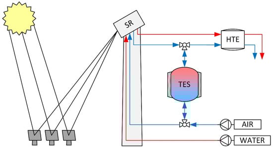
Figure 1.
Simplified schematic CSP process layout without showing heat recuperation of the high-temperature electrolysis exit streams. Red and blue lines show the water/steam and air path, respectively.
Receiver technologies for steam evaporation have been developed and tested [57,58,59]. The exit streams of the receiver are used to power the indented process and charge a TES. The storage is operated in a certain temperature range between charge and discharge. Therefore, process streams are preheated to increase overall system efficiency. Within the investigated process, heat from the exit streams of the HTE is recuperated to preheat the input mass streams. Thus, TES operational temperatures are defined as 850 °C and 450 °C on the hot and cold sides of the storage, respectively. Furthermore, a utility scale with a 100 MWel HTE is considered. The mass flow for charging the TES is 500,000 kg/h and 240,000 kg/h for discharging to maximize the operational full load hours of the HTE. The mass flows were estimated in the process simulation by upscaling the operating parameters of a small HTE stack.
The use of thermochemical reacting material offers higher volumetric energy capacity due to the additional reactive heat. Therefore, TES dimensions can be decreased. Thus, containment costs can be reduced. A numerical analysis must be carried out to identify proper material selection and placement. For this, a packed bed thermal energy storage model considering the heat of thermochemical reaction is developed and used for a parametric study using different material properties.
2.2. Packed Bed Thermal Energy Storage Model
A one-dimensional (1D) two-phase model is developed to investigate the storage behavior. The phases can be distinguished into a gaseous and solid phase. The model is based on a model presented by Schumann [60], which was extended by considering additional phenomena [22]. The presented model considers thermal conduction, thermochemical reactive heat and temperature and pressure-dependent thermophysical gas properties. The used two-phase model consists of an energy equation for each phase:
where T is the temperature, ρ the density, cp the specific heat capacity, hv the volumetric heat transfer coefficient, λeff,s the effective thermal conductivity of the bed, ΔQTC the reactive heat, u the gas phase velocity and ψ the average bed porosity. The subscripts s and g stand for the solid and gas phase, respectively. Here, the solid phase energy conservation considers the energy term of the thermochemical redox reaction as it takes place in the solid phase. In this study, the use of thermochemical reactive materials is of interest, and therefore it is sufficient to neglect the change of thermophysical properties of the solid material to determine the effects of reactive heat. The impact of using constant or variable properties has been studied by Zanganeh et al. [61] and Agalit et al. [62]. They concluded that the temperature is predicted to be high in the hot region and low in the cold region of the TES because the specific heat capacity is predicted incorrectly. Nevertheless, the behavior of the thermocline is representative of such systems. Since the analysis of the thermochemical heat of a non-stoichiometric reaction is of interest, the constant material property method is sufficient. The gas is considered ideal because the operating pressure is close to ambient pressure. In addition, the change of oxygen concentration in the gas flow is neglected, since the mass flow rate is high. Therefore, oxygen partial pressure pO2 is considered to be constant and equal to ambient pO2amb. This has two effects. Firstly, the initial redox reaction extension is minimal and this state of the reaction is considered. Secondly, the redox reaction is only affected by temperature changes. The TES geometry can be represented as an ideal cylindrical shape and a homogeneous bed porosity of 40% is used. Furthermore, we consider an axial Newtonian plug flow without a radial flow direction. To conclude, the following assumptions are considered:
- No significant radial effects (1D model is sufficient).
- Particle behavior can be described as a continuum.
- Gases can be considered ideal.
- Solid phase thermophysical properties are constant.
- Change of species in the gaseous phase is neglected.
- The reaction rate is not limiting (reaction takes place instantaneously).
- Axial plug flow.
Based on the assumptions made, we can simplify the heat transfer between the solid and gaseous phases to a volumetric heat transfer coefficient. Equations (2) and (3) are coupled with a volumetric heat transfer coefficient which is calculated based on a Nusselt correlation:
λg is the thermal conductivity of the HTF and dp the particle size of the solid filler. The factor Sv is the volume-specific surface area of a particle. Assuming perfectly spherical particles Sv = 6(1 − ψ)/dp. The Nusselt number Nu is calculated using the correlation of Wakao et al. [63]:
The Nusselt number is a function of the Reynolds (Re) and Prandtl (Pr) numbers. For packed beds, the Reynolds number is calculated using the empty volume velocity u0 and the bed porosity:
The Prandtl number is defined as:
Based on the expected mass flows and temperatures, the Reynolds number is within the given range of the model 15 < Re < 8500 [63]. Furthermore, thermal diffusion is considered in the energy balance for the solid phase and uses an effective bed thermal conductivity λeff,s which is calculated using the Zehner, Bauer, Schlünder model (ZBS model) [64], which has a reasonably high accuracy [65]. The model considers the thermal conductivity of both phases and, additionally, the heat transfer through radiation between the solid particles.
For the gaseous phase of the two-phase model, the pressure drop along the bed axis length L is calculated as the gas-specific density depends on the local pressure and temperature. Thus, local pressure is calculated using a correlation of the Ergun type with a correction factor proposed by Brauer [64,66]:
Here, K1 = 160 and K2 = 3.1 and the Sauter diameter ds = 6/Sv is used where the latter describes the void fraction diameter. The heat of the thermochemical reaction is considered with the volumetric change in enthalpy ΔQTC:
where dXR/dt describes the reaction rate which is assumed to be not limiting for the investigated time steps and where dδ is the change of the reaction extension, Δho the partial molar enthalpy and Ms the molar mass of the reactive material.
2.3. Boundary Conditions and Numerical Discretization
Equations (2) and (3) are solved fully implicitly in a linear algebraic equation solver in python. Since the implicit solution is stable for all timesteps, the calculated timestep can be larger without increasing mesh element size according to the Courant–Friedrichs–Lewy condition for explicit CFD solutions. The spatial discretization uses the finite volume method with an upwind difference scheme for the first-order derivative and a central difference scheme for the second-order derivative. Additionally, the following boundary conditions apply to the TES model for charging ( > 0), discharging ( < 0) and standby ( = 0):
Additionally, the temperature-dependent properties (λg, cp,g, ρg, ν) and parameters (λeff,s, hv, p, ΔH) are calculated explicitly for each time step using the calculated temperature of the previous time step. The gas properties λg, cp,g and ν are calculated using polynomial fit [64] and, for the density, the ideal gas law.
Figure 2 visualizes the packed bed storage and summarizes the thermal, fluid mechanical and thermochemical processes. Additionally, the TES dimensions are depicted as they are used for spatial discretization and boundary conditions.
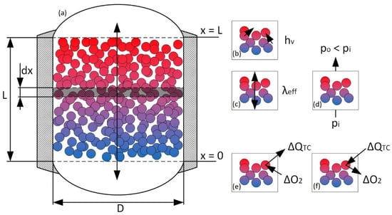
Figure 2.
Schematic visualization of the TES interior (a). The colored particles form a natural porosity with a void fraction (white background) of about 40%. Furthermore, the dimensions are displayed for a better understanding of the boundary conditions. (b) effective volumetric heat transfer coefficient between the heat transfer media (air) and the solids. (c) effective bed conductivity along the storage axis based on thermal conductivity and radiation. (d) pressure drop due to the porous media flow through the packed bed. (e,f) reactive heat ΔQTC due to oxidation and reduction of the solid redox material.
2.4. Model Verification
The numerical model and the used discretization method are verified using experimental data published by Meier et al. [67] and reprocessed by Hänchen et al. [68]. The set of data has been used regularly in the past for model verification [62,68,69]. Since the data were derived from pure sensible thermal energy storage, the term considering the heat of the thermochemical reaction is set to zero for comparison. For the verification of the numerical simulation, the volumetric heat transfer coefficient is calculated using the empirical equation of Coutier and Faber [70] using the packed bed particle diameter dp and the mass flow rate per unit cross section G0 = /A:
This correlation has been derived using experimental data of a similar setup to the one of Meier et al.; therefore, a good agreement shall be found to verify newly developed numeric procedures. In Figure 3, an agreement between the numerically calculated temperature profile (black lines) and the experimentally measured temperature (red markers) is achieved and the model implementation can be considered verified. However, the model of Coutier and Faber neglects the fluid phase property change due to a change in temperature. Therefore, the model by Wakao et al. is used for the parametric study as it also covers a large range of Reynolds numbers and is in the average of other correlations [22].
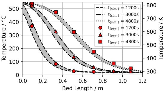
Figure 3.
Model verification by comparing numerical results with experimental data published by Meier et al. [67] and reprocessed by Hänchen et al. [68]. The grey surfaces indicate the temperature difference between the solid and gaseous phases of the two-phase model.
2.5. Inert and Redox Material Specific Properties
For the TES evaluation, inert and reactive materials are investigated. Bauxite is used as an inert material since it is a commonly used particle in CSP research due to its high specific heat capacity and mechanical stability. Furthermore, this material can be used at higher temperatures and therefore is suited for future experimental validation. For a comparison of different reactive materials, SFO, CMO and CSMO were selected. These have different reaction temperatures and different reaction enthalpies and entropies [37,46,47,51,52,53,54,71,72].
2.5.1. Redox Thermodynamics
For the model implementation of the reactive heat of redox reaction, the redox thermodynamics of a non-stoichiometric reacting material need to be considered. The standard thermal equilibrium of a reaction is in general a function of oxygen partial pressure and temperature.
To obtain the partial molar entropy, Bulfin et al. [55] proposed the dilute species model to calculate the partial molar entropy:
where, the thermal entropy change stems from the entropy of oxygen. The second term on the right-hand side of Equation (12) has been derived for the redox reaction of ceria but was shown to be applicable for other perovskites as well [52,55]. Combining Equations (11) and (12) gives an equation of state
which can be used for perovskites with constant enthalpy change. In some cases, it is necessary to include a dependency on δ and T for Δho [52]. Equation (13) has been used to carry out a parameter fit to evaluate Δsth and a for CMO and CMSO [52], listed in Table 1. For SFO, the same equation is used on the experimental data published by Vieten et al. [51]. Thus, Δsth = 105 kJ/mol and a = 2.2 are determined for a constant partial molar enthalpy change of Δho = 100 kJ/mol.

Table 1.
Thermophysical and thermodynamic properties for selected perovskites and bauxite.
In the TES model, Equation (13) is used to calculate δ for a given temperature and time during charge and discharge. The difference of vacancies Δδ to the previous calculated time step is then used to calculate the reactive heat for the given change in non-stoichiometry using Equation (9).
2.5.2. Solid Filler Material Properties
The thermophysical and thermodynamic properties of selected materials are summarized in Table 1. For the reactive materials, the same specific heat capacity is used due to their similarities in a lattice structure. Furthermore, similar specific heat capacities were found for other perovskites [46]. Based on the thermophysical material properties, the volumetric heat capacities cv of the selected material are comparable. The Ca-based perovskites CMO and CSMO have a similar high cv as bauxite. Thus, a change in storage capacity due to the utilization of the thermochemical reactive heat can be investigated. Additionally, we can investigate different redox thermochemistry by comparing SFO with CMO and CSMO. The comparison can be used for future applications of the selected materials and others by comparing their reactive behavior and thermophysical properties.
2.6. Thermal Energy Storage Analysis
Based on the process operation condition, the mass flows for charging and discharging and their respective temperatures are defined. The charging power is assumed to be 60 MWth and the storage shall be fully charged within 9 h. For the investigated system, an aspect ratio α = L/D = 1 with a height L and diameter D of 14 m is used, thus resulting in a storage volume of V = 2155 m3. Considering an average bed porosity of ψ = 0.4 the specific volumetric storage capacity can reach 5077 MJ/K (1.41 MWh/K) using bauxite.
The charging and discharging temperature and mass flows are assumed to be constant. Thermal losses will be neglected in the parametric study, as they only occur in the near-wall regions. Furthermore, radial thermal diffusion is low due to the low thermal bed conductivity. The emissivity coefficient is assumed to be 0.85 and the same for each solid material. ψ, λs and dp are also assumed to be the same for the selected solids. In contrast to the geometric parameters, λs is a material-specific property but does not highly affect the TES operation [68].
2.6.1. Operational Constraints
In the numerical simulation, different operational constraints are considered. Due to the investigated process, the gas temperature at the outlet and inlet must be within certain boundaries for the TES. Therefore, the dimensionless temperature θ is used.
Cascetta et al. [23] investigated an improvement in cycling stability for a threshold of θhot = 0.8 and θcold = 0.2 for the hot and cold sides of the TES, respectively. As the gas temperature during discharge shall not be below 800 °C for the HTE, θhot = 0.875 is used. At the cold side, θcold = 0.2 is considered. Additionally, time constraints apply to the investigated case. As the TES is integrated into a solar-powered process, the storage charging time is limited by the sunshine time of the investigated location. In this study, the maximum full load charging time tcmax is set to 9 h. Hence, the discharging time is 15 h as long as the outlet temperature constraints are not violated. However, if the effective charging duration is less than 9 h, the maximum discharging time tdamx is equivalent to the difference between the total daytime of 24 h and the current duration of charging tcend until one of the constraint’s temperatures or maximum charging time is met.
In the numerical calculation, the TES outlet temperature is compared to θhot and θcold during discharging and charging operations, respectively. Furthermore, the current time step of the ongoing simulation is compared to the maximum charging or discharging time. If either temperature threshold or maximum time is reached, TES operation is switched to either discharging or charging the storage. Figure 4 displays the temperature profiles of the solid phase at the end of charge and discharge, respectively, for an exemplary case. In this figure, the flow direction for each case is visualized by the red and blue arrows and the temperature thresholds θcold and θhot for the gaseous phase are plotted as dotted lines. The area between both lines is the usable storage capacity.
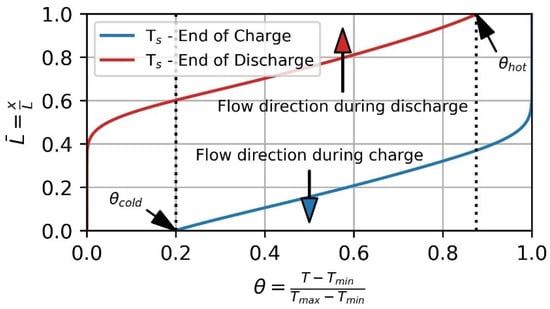
Figure 4.
Temperature profile at the end of charge (blue) and end of discharge (red) for the solid phase. Threshold values θcold and θhot for the gaseous phase outlet temperature during charge and discharge, respectively. The ordinate represents the normalized storage height and the abscissa corresponds to the dimensional temperature θ.
2.6.2. Parametric Study
In this study, the effect of replacing inert particles with reactive material is investigated in order to evaluate the storage performance based on selected perovskite and positioning. Therefore, 4 different combinations of inert and reactive materials are investigated and compared to the base case (V0) with inert particles only, see Figure 5.
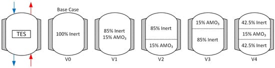
Figure 5.
Cascading variations of inert and reactive material. The TES is operated in a cycling approach. During charging (blue) the flow direction is from top to bottom and vice versa during the discharge (red) of the TES.
V1, V2, V3, and V4 have 15% of their volume replaced by selected perovskite. In V1, the material is evenly distributed in the whole storage volume. In V2, V3, and V4, the material is located at the bottom, top and middle, respectively. Thus, the reactive material is charged and discharged under different operation conditions. In V2, the reactive material is placed at the cold end and is not heated to the maximum temperature. By placing it on top of the storage (V3), the material will never cool down to the minimum temperature. In cases V2 and V3, the heat stored as sensible heat in the reactive material is expected to be small compared to V1 and V4. Furthermore, it is expected that the stored sensible heat is the highest in V4. In the center of the TES, the material will be exposed to the maximum temperature difference between the end of charge and discharge and, therefore, the thermochemical stored heat is expected to be the highest as well.
Using different material properties, it is expected to see different storage behavior for the different cases and for the sensible stored heat in the inert particles. Table 2 summarizes the simulation parameters which are assumed to be the same for the investigated variations (e.g., the emissivity ε, thermal conductivity λs and particle diameter dp of the solids). The storage height is discretized in nz = 120 elements. Thus, a volume replacement of 15% can easily be represented in the numerical model.
Table 2.
Packed bed TES numeric simulation parameters. Subscripts c and d stand for charging and discharging, respectively.
2.7. Evaluation Method
Different indicators are important for TES operation. First, discharge time shall be as long as possible at the highest temperature. Second, storage capacity utilization should be maximized to minimize the size of the TES and reduce investment costs. The thermal energy storage capacity of the filler material for a pure sensible TES is
However, Equation (15) also applies to the sensible heat of a reactive material. The total heat stored in a reactive material is the sum of the sensible heat and the chemical stored heat of the reaction where the latter calculated as
with ΔQTC from Equation (9). Thus, the impact of using reactive material on the total storage capacity = can be studied.
3. Results and Discussion
To evaluate the use of thermochemical reactive material, the storage capacity of the introduced concepts using SFO, CMO and CSMO is compared to the base case V0 with inert particles only. The temperature profile of 15 consecutive charge and discharge cycles of V0 is depicted in Figure 6. The dashed lines show the thermoclines at the end of charge and discharge for the previous cycles and the yellow-colored area is the one between the thermoclines of cycle 15. With the increasing cycle number, the thermoclines become flattered, and, therefore, the area between the thermocline at end of charge and discharge decreases. Consequently, degradation occurs. After 15 consecutive cycles, further degradation is negligible. Therefore, this state is referred to as a steady state and a usable storage capacity of 331.66 MWh can be derived for V0.
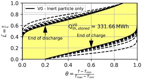
Figure 6.
Thermocline in steady state condition at the end of charge and discharge after 15 cycles (solid black line) of the base case (V0) with inert particles only. Dashed lines indicate the thermocline before a steady state is reached.
3.1. Thermocline Behavior and Storage Capacity Analysis
The results of packed bed simulation with additional redox reactive material show an effect on storage capacity and change in thermocline behavior. The results of the different variations (i.e., V1, V2, V3, and V4) are compared to the base case V0. Figure 7 summarizes the resulting thermoclines at the steady state of the four different cases (solid lines) in comparison to the base case (dashed lines) using the different reactive materials. The yellow-colored areas indicate a worse thermocline behavior and the blue-colored areas show a better performing thermocline. Similarly, yellow indicates a decrease and blue an increase in sensible stored heat compared to the base case V0. The results show that the location of the perovskites can have a significant effect from increasing the storage capacity by several percent to having no effect at all. Moreover, choosing a suitable material for a location is crucial since, at the wrong location, CMO, for example, can even decrease the overall capacity. However, the additional heat stored in the thermochemical reaction can be sufficient to achieve higher storage capacity. The overall best performing case is V2 using SFO with an increased capacity by about 35 MWh (i.e., 10.5%). The high volumetric heat capacity and the reactive heat affect the thermocline at the end of the charge the most. Hence, the thermocline gradient close to the bottom of the TES at the end of the charge is the highest for V2 with SFO.
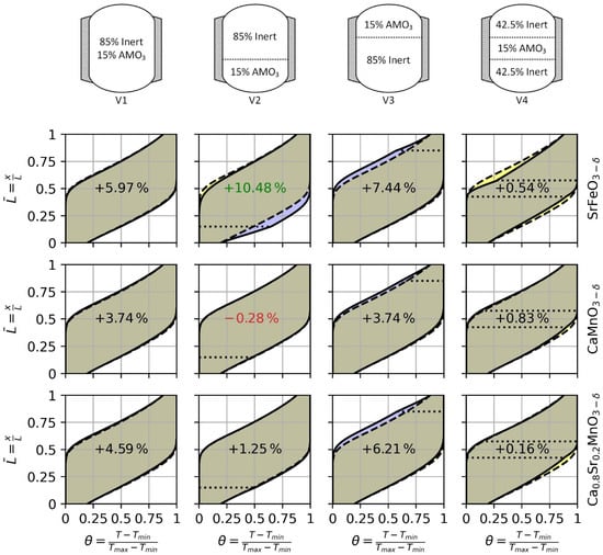
Figure 7.
Thermoclines behavior after 15 cycles of the four investigated storage concepts with SrFeO3−δ, CaMnO3−δ and Ca0.8Sr0.2MnO3−δ. The dashed line shows the thermocline at end of charge and discharge of the base case (V0) and the solid line shows the thermocline of V1, V2, V3, and V4 for the selected perovskite. The purple and yellow area indicate an increase and decrease of the local material utilization, respectively.The dotted lines indicate the placement of the reactive material in V2, V3 and V4. The values in the center of each figure show the change in storage capacity compared to the base case (V0).
As shown in Table 1, SFO has the highest volumetric heat capacity meaning that even without reaction, SFO is capable of storing the most heat in a given volume. The volumetric heat capacity of bauxite and CSMO differs only by less than 1% with bauxite showing the higher storage performance. Therefore, replacing a certain amount of bauxite by CSMO shows approximately the pure impact of the thermochemical reaction for heat storage purposes. The highest impact of the thermochemical reaction using CSMO can be achieved if the material is placed at the top of the TES (i.e., V3). Thus, thermocline behavior at the end of discharge is improved increasing the storage capacity of the remaining 85% of non-reactive material compared to V0. We can conclude that CSMO is reacting at higher temperatures. In comparison, CMO shows a similar thermocline behavior to CSMO. Comparing V1 and V3 using CMO the same increase in storage capacity is achieved. In V3, the behavior of the thermocline is improved resulting in higher storage capacity, for the same reason as when using CSMO. In V1, the reactive material is evenly distributed and the non-reactive material is exposed to the same temperature difference as the reactive material. The increase in storage capacity is achieved successively through the thermochemical reaction since CMO has a lower volumetric heat capacity than bauxite. The replacement of 15% of the volume in the center of the TES (i.e., V4) will result in a disruption of the thermocline in the remaining 85% of a non-reactive material. Thus, the effective storage capacity of the bauxite is lower compared to V0.
In Figure 8 the usable storage capacity of the three perovskites for each case and additionally the reference case is displayed. For the bar plots, the contribution of the sensible heat of the 85% bauxite as well as the sensible and reactive heat of the 15% perovskite is given. Overall, the main storage capacity is provided by the sensible heat of the material and the contribution by the chemical reaction is comparatively small. The cases using CSMO are investigated first, as CSMO and bauxite have a small difference in sensible volumetric heat capacity. Replacing 15% of the bauxite with CSMO on top of the TES (V3) will result in the highest increase in storage capacity using CSMO. Based on the initial assumptions for the temperature threshold at the hot/cold in/outlet comparing V2 and V3, the reactive material in V2 is exposed to the larger change in temperature between the end of the charge and discharge. Thus, in V2, the capacity stored in the reactive material as sensible heat is larger. In V3, however, the reactive heat of CSMO can compensate for the lower sensible heat capacity. Consequently, the increase in storage capacity is due to the heat of the thermochemical reaction. In the cases using SFO, it can be seen that SFO performs better in the colder part of the storage because of the higher usable temperature difference and its high volumetric heat capacity. Additionally, we see a higher amount of chemically stored heat compared to V3. Hence, V2 will result in the overall highest increase in storage capacity. However, the overall highest reactive heat is stored in V4 as the reactive material will be exposed to the highest temperature change. Despite the heat storage capacity of the reactive material being utilized the most in V4, for all investigated materials, the highest storage capacity is achieved in either V2 or V3 depending on the used material. In V4, the reactive material has a higher heat capacity than the bauxite. Thus, the thermocline is disrupted resulting in lower storage capacity in the remaining 85% of the non-reactive material. The use of CMO as the reactive material results in a similar thermocline and storage behavior to the use of CSMO. However, having a much lower cv than bauxite, the overall storage capacity can be less than the base case. The utilization of reactive heat is not sufficient in V2 to compensate for the difference between CMO and bauxite in volumetric heat capacity. Thus, the storage capacity is decreased by 0.28%.
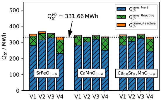
Figure 8.
Thermal energy stored in the different cases investigated. The dotted horizontal line shows the thermal energy stored in the base case (V0) with an inert particle only.
The replacement of 15% volume in the center of the TES will result in the highest capacity utilization of the reactive material, as depicted in Figure 8. However, this results in a disruption of the thermocline in the remaining 85% of non-reactive material which can be identified in Figure 7. Thus, the material with higher heat capacity must be placed either at the inlet or outlet of the TES. This behavior can be identified for all selected materials. The highest storage capacity for the reactive material can be found in V4 but overall storage capacity is low. We conclude this effect does occur for V1 as well. In V1, 15% of the reactive material is distributed evenly. Nevertheless, in the center of the TES, the capacity provided by the thermochemical reaction is the highest. Thus, the heat capacity in this area is the highest. The difference in heat capacity from the center to the outer region will also result in a negative behavior of the thermocline.
In the proposed configurations and fixed TES dimensions, the storage capacity can be increased. The use of SFO or CSMO achieves an increase in storage capacity for all variations. In V2 using CMO, a decrease in storage capacity is investigated. V1 in general achieves an increased storage capacity. However, the change in thermocline behavior is neglectable small. In contrast, V2–V4 shows an impact on the thermocline behavior. V2 improves the thermocline at the end of the charge and V3 at the end of the discharge. The thermoclines in the V4 configuration are negatively impacted even though the reactive heat is utilized most. However, the effective charging and discharging time is increased for the configuration with higher storage capacity. On the other hand, the TES dimension can be decreased for the same storage capacity and operation time-saving construction costs. However, a detailed techno-economic analysis must be carried out to identify the best storage capacity and configuration for the lowest hydrogen production costs.
3.2. Analysis of the Reactive Material
As the impact of the analyzed perovskites differs significantly, a material analysis is carried out to identify the potential of using perovskites for increasing the usable storage capacity. Based on the assumption of not limiting reaction kinetics the molar oxygen supply to the TES must be sufficient to oxidize the reduced material. During oxidation, oxygen molecules must be present for the reaction. Based on the mass flow of 240,000 kg/h during the discharge, the molar flow of oxygen is calculated
using the molar mass of air MAir and the molar fraction of O2 xO2. Based on the estimated operation temperatures of 450–850 °C and using Equation (13), a maximum change of Δδ = 0.14625, 0.02642 and 0.050435 is expected for SFO, CMO and CSMO, respectively. Considering the different cases selected for the parametric study, a 15% replacement of the volume by reactive material will result in a maximum oxygen amount of about 793,000 mol for a full reaction extension between 450 and 850 °C using SFO. Thus, it takes approximately 1641 s to provide the needed oxygen molecules for the full reaction using the estimated molar flow from Equation (17). However, due to the thermocline behavior of the TES and the non-stoichiometric reaction behavior, the full reaction extension does not take place at the same time during the cycling operation of the TES. For the used time step dt = 10 s, the maximum amount of oxygen cycled in the reaction is nmax = 1208.13 mol for V1 using SFO. Thus, it is less than the supplied oxygen rate of 483 mol/s (=4630 mol in 10 s). Low oxygen partial pressure affects the reaction rate and the non-stoichiometric reaction extension of the perovskites [51,52,53,75]. Thus, oxidation can be slowed. Therefore, this assumption is not applicable to lower mass flow rates. However, the highest change in reaction occurs during the initial TES cycle, when the storage is charged for the first time. For the initial cycle, the temperature difference between the heat transfer media and the storage material is the highest and the reaction extension is expected to be the highest as well. However, the initial cycle is not of interest in this study. In the following cycles, the maximum amount of oxygen cycled is 445.89 mol per time step. Thus, about 10 times more oxygen is supplied during the same time period. Therefore, the change of oxygen concentration in the gaseous phase can be neglected in the investigated scenario.
Using the material-specific properties in Table 1, the reaction enthalpy of the selected perovskites is calculated. Figure 9 shows the temperature-dependent change in the non-stoichiometric reaction extension Δδ for a temperature change of 1 K. SFO shows the largest change per 1 K at 400 °C. At higher temperatures, the reaction extension decreases. For CMO and CSMO the peak is not reached in the investigated temperature range. However, CSMO can be reduced at lower temperatures compared to CMO.
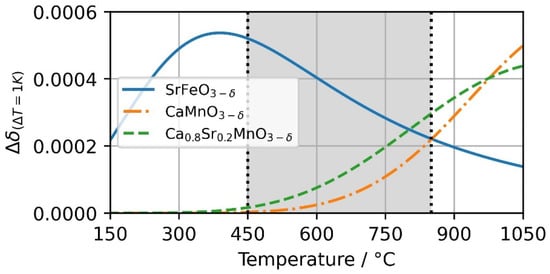
Figure 9.
Change in non-stoichiometry Δδ based on temperature change of 1K at pO2 = 0.18 bar. The change of SrFeO3−δ, CaMnO3−δ and Ca0.8Sr0.2MnO3−δ is visualized over a temperature range from 150 to 1050 °C.
The effective utilization of the heat of reaction is visualized in Figure 10. In the operational scenario between 450 and 850 °C, SFO undergoes the largest change in non-stoichiometry (see also Figure 8) and therefore utilizes the highest heat of reaction. For CMO and CSMO, overall higher temperatures are more favorable for the use of a thermochemical energy storage material. In the temperature range of 800–850 °C, CSMO has the largest change in enthalpy per kg oxide and SFO in lower temperature range. The redox reaction performance of the selected material explains the investigated thermocline and storage capacity behavior. Figure 9 also shows that no analyzed perovskite is ideally suited for the analyzed temperature range. However, newly developed materials from the class of perovskites might be better suited.
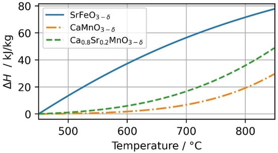
Figure 10.
Reaction heat for SrFeO3−δ, CaMnO3−δ and Ca0.8Sr0.2MnO3−δ in the investigated temperature range of 450–850 °C at pO2 = 0.18 bar.
Perovskite with the structure AMO3−δ is able to be tuned by varying the A and M site ions. We presented two different perovskites (SFO and CMO) and one with an additional ion on the A site lattice of the material (CSMO). Further, perovskites can be tuned with two A and two M site ions resulting in [76]. Vieten et al. [76] experimentally evaluated 24 different perovskite compositions for validating a perovskite design method. Among these, CaxSr1−xMnyFe1−yO3−δ can be a promising perovskite mixture for the investigated setup, e.g., depending on the x and y amount of A and M site doping, respectively, they could offer a favorable redox behavior close to the upper boundary temperature of 850 °C. Thus, the change in stoichiometry could take place in a temperature range between the investigated SFO and CMO, e.g., a hypothetical redox behavior of a CaxSr1−xMnyFe1−yO3−δ configuration is depicted in Figure 11 together with SFO. For this, the parameters Δh0, Δsth and a of Equations (11)–(13) were changed in a range between these of SFO and CMO. Both materials have their peaks close to the boundary temperatures of the investigated case.
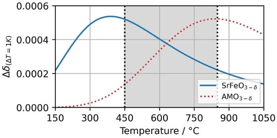
Figure 11.
Change in non-stoichiometry Δδ based on temperature change of 1K at pO2 = 0.18 bar. The change of SrFeO3−δ and a hypothetical AMO3−δ perovskite is visualized over a temperature range from 150 to 1050 °C.
Figure 12 shows the thermocline behavior of such a configuration. The hypothetical perovskite with similar reactive behavior to SFO but at a higher temperature is located in the top (hot area) of the TES. In the bottom (cold area) of the TES SFO is located. This combined 15% volume replacement results in an improved thermocline behavior and increases the heat capacity of the remaining 85% non-reactive bauxite particles. Thus, the overall storage capacity is increased by 14.19% compared to the base case V0. Nevertheless, thorough material research must be carried out to identify the best suited real storage material.
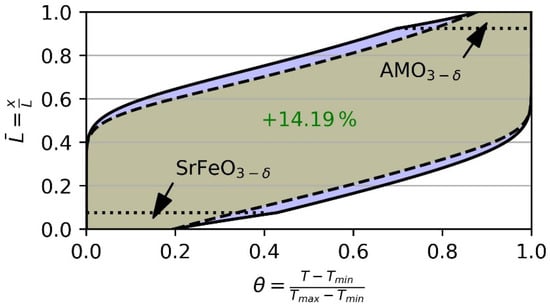
Figure 12.
Possible thermocline behavior of a cascaded storage with 7.5% volume replacement by SrFeO3−δ at the bottom and a hypothetical AMO3−δ perovskite at the top of the storage. In the remaining 85% in the center of the TES bauxite was considered. Thus, storage capacity is increased by 14.19% (local increase indicated by purple area) compared to the base case V0 (dashed black lines) using non-reactive particles only.
4. Conclusions
A packed bed model utilizing the heat of a thermochemical reaction is developed and analyzed to quantify the impact of thermochemical reactions at different locations in storage. Based on the selection of three perovskites (SrFeO3−δ, CaMnO3−δ and Ca0.8Sr0.2MnO3−δ) four different configurations of 15% reactive and 85% non-reactive materials were analyzed. The use of reactive material can decrease thermal degradation in cyclic operation and thereby increase the storage capacity. However, the partial replacement of inert particles must be suitable for the materials’ reaction and perovskites are potential material candidates. For identifying a suitable perovskite, the non-stoichiometric reaction extension at the end of charge and discharge and the redox thermodynamics of the selected material must be studied carefully. Furthermore, sensible thermal storage characteristics of the perovskites such as the specific heat capacity and material density are also important for the thermal energy storage operation. Nevertheless, the reactive heat does increase the volumetric heat capacity and thereby increases the energy density of the storage. For the investigated operation conditions, the storage capacity can be increased by up to 10.48% if 15% of the inert particles are replaced by the thermochemical reactive material SrFeO3−δ. Thus, SrFeO3−δ is suited best for the investigated process. A higher share of reactive material will increase the storage capacity further, but an optimal share must be found by a techno-economic analysis. Furthermore, material production and material stability must be investigated in an experimental setup.
The results and the model of this study will be used in concentrated solar-powered high-temperature electrolysis process analysis. Due to the transient behavior of solar energy, a detailed combined process and TES analysis is needed to determine hydrogen yield and production costs. Furthermore, an experimental investigation of non-stoichiometric reacting material will be carried out for experimental analysis and model comparison.
Author Contributions
Conceptualization, T.R., K.R. and N.M.; methodology, T.R.; software, T.R.; writing—original draft preparation, T.R.; writing—review and editing, T.R., K.R. and N.M.; visualization, T.R.; supervision, K.R. and N.M.; project administration, K.R. and N.M.; funding acquisition, C.S.; All authors have read and agreed to the published version of the manuscript.
Funding
This research received no external funding.
Institutional Review Board Statement
Not applicable.
Informed Consent Statement
Not applicable.
Data Availability Statement
Datasets generated during the current study are available from the corresponding author on reasonable request.
Conflicts of Interest
The authors declare no conflict of interest. The funders had no role in the design of the study; in the collection, analyses, or interpretation of data; in the writing of the manuscript, or in the decision to publish the results.
References
- Ram, M.; Galimova, T.; Bogdanov, D.; Fasihi, M.; Gulagi, A.; Breyer, C.; Micheli, M.; Crone, K. Powerfuels in a Renewable Energy World. Global Volumes, Costs, and Trading 2030 to 2050; Lappeenranta: Berlin, Germany, 2020. [Google Scholar]
- IEA/International Energy Agency. Achieving Net Zero Heavy Industry Sectors in G7 Members; OECD: Paris, France, 2022. [Google Scholar] [CrossRef]
- International Renewable Energy Agency (IRENA). Reaching zero with Renewables: Biojet Fuels; IRENA: Abu Dhabi, United Arab Emirates, 2021. [Google Scholar]
- Gandía, L.M.; Arzamedi, G.; Diéguez, P.M. (Eds.) Renewable Hydrogen Technologies. Production, Purification, Storage, Applications and Safety; Elsevier: Amsterdam, The Netherland, 2013. [Google Scholar]
- Sanz-Bermejo, J.; Muñoz-Antón, J.; Gonzalez-Aguilar, J.; Romero, M. Optimal integration of a solid-oxide electrolyser cell into a direct steam generation solar tower plant for zero-emission hydrogen production. Appl. Energy 2014, 131, 238–247. [Google Scholar] [CrossRef]
- Roeb, M.; Monnerie, N.; Houaijia, A.; Sattler, C.; Sanz-Bermejo, J.; Romero, M.; Canadas, I.; Castro, A.D.; Lucero, C.; Palomino, R.; et al. Coupling Heat and Electricity Sources to Intermediate Temperature Steam Electrolysis. J. Energy Power Eng. 2013, 7, 2068–2077. [Google Scholar]
- Lin, M.; Haussener, S. Techno-economic modeling and optimization of solar-driven high-temperature electrolysis systems. Sol. Energy 2017, 155, 1389–1402. [Google Scholar] [CrossRef]
- Grube, T.; Reul, J.; Reuß, M.; Calnan, S.; Monnerie, N.; Schlatmann, R.; Sattler, C.; Robinius, M.; Stolten, D. A techno-economic perspective on solar-to-hydrogen concepts through 2025. Sustain. Energy Fuels 2020, 4, 5818–5834. [Google Scholar] [CrossRef]
- Seitz, M.; von Storch, H.; Nechache, A.; Bauer, D. Techno economic design of a solid oxide electrolysis system with solar thermal steam supply and thermal energy storage for the generation of renewable hydrogen. Int. J. Hydrogen Energy 2017, 42, 26192–26202. [Google Scholar] [CrossRef]
- Monnerie, N.; von Storch, H.; Houaijia, A.; Roeb, M.; Sattler, C. Hydrogen production by coupling pressurized high temperature electrolyser with solar tower technology. Int. J. Hydrogen Energy 2017, 42, 13498–13509. [Google Scholar] [CrossRef]
- Houaijia, A.; Roeb, M.; Monnerie, N.; Sattler, C. Solar power tower as heat and electricity source for a solid oxide electrolyzer: A case study. Int. J. Energy Res. 2015, 39, 1120–1130. [Google Scholar] [CrossRef]
- Puig-Samper, G.; Bargiacchi, E.; Iribarren, D.; Dufour, J. Assessing the prospective environmental performance of hydrogen from high-temperature electrolysis coupled with concentrated solar power. Renew. Energy 2022, 196, 1258–1268. [Google Scholar] [CrossRef]
- Petipas, F.; Brisse, A.; Bouallou, C. Benefits of external heat sources for high temperature electrolyser systems. Int. J. Hydrogen Energy 2014, 39, 5505–5513. [Google Scholar] [CrossRef]
- Rosenstiel, A.; Monnerie, N.; Dersch, J.; Roeb, M.; Pitz-Paal, R.; Sattler, C. Electrochemical Hydrogen Production Powered by PV/CSP Hybrid Power Plants: A Modelling Approach for Cost Optimal System Design. Energies 2021, 14, 3437. [Google Scholar] [CrossRef]
- Godula-Jopek, A.; Stolten, D. Hydrogen Production: By Electrolysis; John Wiley & Sons, Incorporated: Berlin, Germany, 2015. [Google Scholar]
- Heddrich, M.P.; Gupta, S.; Santhanam, S. Electrochemical Ceramic Membrane Reactors in Future Energy and Chemical Process Engineering. Chem. Ing. Tech. 2019, 91, 809–820. [Google Scholar] [CrossRef]
- Lang, M.; Raab, S.; Lemcke, M.S.; Bohn, C.; Pysik, M. Long-Term Behavior of a Solid Oxide Electrolyzer (SOEC) Stack. Fuel Cells 2020, 20, 690–700. [Google Scholar] [CrossRef]
- Chapman, A.; Ertekin, E.; Kubota, M.; Nagao, A.; Bertsch, K.; Macadre, A.; Tsuchiyama, T.; Masamura, T.; Takaki, S.; Komoda, R.; et al. Achieving a Carbon Neutral Future through Advanced Functional Materials and Technologies. BCSJ 2022, 95, 73–103. [Google Scholar] [CrossRef]
- Xie, B.; Baudin, N.; Soto, J.; Fan, Y.; Luo, L. Thermocline packed bed thermal energy storage system. In Renewable Energy Production and Distribution; Elsevier: Amsterdam, The Netherlands, 2022; pp. 325–385. [Google Scholar] [CrossRef]
- Cabeza, L.F. Advances in Thermal Energy Storage Systems: Methods and Applications; Elsevier Science & Technology: Cambridge, UK, 2014. [Google Scholar]
- Buck, R.; Schwarzbözl, P. 4.17 Solar Tower Systems. In Comprehensive Energy Systems; Elsevier: Amsterdam, The Netherlands, 2018; pp. 692–732. [Google Scholar] [CrossRef]
- Esence, T.; Bruch, A.; Molina, S.; Stutz, B.; Fourmigué, J.-F. A review on experience feedback and numerical modeling of packed-bed thermal energy storage systems. Sol. Energy 2017, 153, 628–654. [Google Scholar] [CrossRef]
- Cascetta, M.; Cau, G.; Puddu, P.; Serra, F. Numerical Investigation of a Packed Bed Thermal Energy Storage System with Different Heat Transfer Fluids. Energy Procedia 2014, 45, 598–607. [Google Scholar] [CrossRef]
- Ortega-Fernández, I.; Uriz, I.; Ortuondo, A.; Hernández, A.B.; Faik, A.; Loroño, I.; Rodríguez-Aseguinolaza, J. Operation strategies guideline for packed bed thermal energy storage systems. Int. J. Energy Res. 2019, 43, 6211–6221. [Google Scholar] [CrossRef]
- Galione, P.A.; Pérez-Segarra, C.D.; Rodríguez, I.; Lehmkuhl, O.; Rigola, J. A New Thermocline-PCM Thermal Storage Concept for CSP Plants. Numerical Analysis and Perspectives. Energy Procedia 2014, 49, 790–799. [Google Scholar] [CrossRef]
- Galione, P.A.; Pérez-Segarra, C.D.; Rodríguez, I.; Oliva, A.; Rigola, J. Multi-layered solid-PCM thermocline thermal storage concept for CSP plants. Numerical analysis and perspectives. Appl. Energy 2015, 142, 337–351. [Google Scholar] [CrossRef]
- Galione, P.A.; Pérez-Segarra, C.D.; Rodríguez, I.; Torras, S.; Rigola, J. Multi-layered solid-PCM thermocline thermal storage for CSP. Numerical evaluation of its application in a 50 MWe plant. Sol. Energy 2015, 119, 134–150. [Google Scholar] [CrossRef]
- Geissbühler, L.; Kolman, M.; Zanganeh, G.; Haselbacher, A.; Steinfeld, A. Analysis of industrial-scale high-temperature combined sensible/latent thermal energy storage. Appl. Therm. Eng. 2016, 101, 657–668. [Google Scholar] [CrossRef]
- Zanganeh, G.; Khanna, R.; Walser, C.; Pedretti, A.; Haselbacher, A.; Steinfeld, A. Experimental and numerical investigation of combined sensible–latent heat for thermal energy storage at 575 °C and above. Sol. Energy 2015, 114, 77–90. [Google Scholar] [CrossRef]
- Cascetta, M.; Petrollese, M.; Oyekale, J.; Cau, G. Thermocline vs. two-tank direct thermal storage system for concentrating solar power plants: A comparative techno-economic assessment. Int. J. Energy Res. 2021, 45, 17721–17737. [Google Scholar] [CrossRef]
- Geissbühler, L.; Mathur, A.; Mularczyk, A.; Haselbacher, A. An assessment of thermocline-control methods for packed-bed thermal-energy storage in CSP plants, Part 1: Method descriptions. Sol. Energy 2019, 178, 341–350. [Google Scholar] [CrossRef]
- Geissbühler, L.; Mathur, A.; Mularczyk, A.; Haselbacher, A. An assessment of thermocline-control methods for packed-bed thermal-energy storage in CSP plants, Part 2: Assessment strategy and results. Sol. Energy 2019, 178, 351–364. [Google Scholar] [CrossRef]
- McTigue, J.D.; Markides, C.N.; White, A.J. Performance response of packed-bed thermal storage to cycle duration perturbations. J. Energy Storage 2018, 19, 379–392. [Google Scholar] [CrossRef]
- Cascetta, M.; Serra, F.; Arena, S.; Casti, E.; Cau, G.; Puddu, P. Experimental and Numerical Research Activity on a Packed Bed TES System. Energies 2016, 9, 758. [Google Scholar] [CrossRef]
- Pardo, P.; Deydier, A.; Anxionnaz-Minvielle, Z.; Rougé, S.; Cabassud, M.; Cognet, P. A review on high temperature thermochemical heat energy storage. Renew. Sustain. Energy Rev. 2014, 32, 591–610. [Google Scholar] [CrossRef]
- Carrillo, A.J.; González-Aguilar, J.; Romero, M.; Coronado, J.M. Solar Energy on Demand: A Review on High Temperature Thermochemical Heat Storage Systems and Materials. Chem. Rev. 2019, 119, 4777–4816. [Google Scholar] [CrossRef]
- Bulfin, B.; Vieten, J.; Agrafiotis, C.; Roeb, M.; Sattler, C. Applications and limitations of two step metal oxide thermochemical redox cycles; a review. J. Mater. Chem. A 2017, 5, 18951–18966. [Google Scholar] [CrossRef]
- Vieten, J.; Gubán, D.; Roeb, M.; Lachmann, B.; Richter, S.; Sattler, C. Ammonia and nitrogen-based fertilizer production by solar-thermochemical processes. In Proceedings of the SOLARPACES 2019: International Conference on Concentrating Solar Power and Chemical Energy Systems, Daegu, South Korea, 1–4 October 2019; AIP Publishing: New York, NY, USA, 2020; p. 170016. [Google Scholar]
- Romero, M.; Steinfeld, A. Concentrating solar thermal power and thermochemical fuels. Energy Environ. Sci. 2012, 5, 9234. [Google Scholar] [CrossRef]
- Agrafiotis, C.; Roeb, M.; Sattler, C. Hybrid Sensible/Thermochemical Solar Energy Storage Concepts Based on Porous Ceramic Structures and Redox Pair Oxides Chemistry. Energy Procedia 2015, 69, 706–715. [Google Scholar] [CrossRef]
- Carrillo, A.J.; Serrano, D.P.; Pizarro, P.; Coronado, J.M. Improving the Thermochemical Energy Storage Performance of the Mn2O3/Mn3O4 Redox Couple by the Incorporation of Iron. ChemSusChem 2015, 8, 1947–1954. [Google Scholar] [CrossRef] [PubMed]
- André, L.; Abanades, S.; Cassayre, L. Experimental Investigation of Co–Cu, Mn–Co, and Mn–Cu Redox Materials Applied to Solar Thermochemical Energy Storage. ACS Appl. Energy Mater. 2018, 1, 3385–3395. [Google Scholar] [CrossRef]
- Tescari, S.; Singh, A.; de Oliveira, L.; Breuer, S.; Agrafiotis, C.; Roeb, M.; Sattler, C.; Marcher, J.; Pagkoura, C.; Karagiannakis, G.; et al. Experimental proof of concept of a pilot-scale thermochemical storage unit. AIP Conf. Proc. 2017, 1850, 90006. [Google Scholar] [CrossRef]
- Staff, P. Thermochemical Heat Storage for Concentrated Solar Power; Thermochemical System Reactor Design for Thermal Energy Stroage; OSTI: Oak Ridge, TN, USA, 2011. [Google Scholar] [CrossRef]
- Agrafiotis, C.; Pein, M.; Giasafaki, D.; Tescari, S.; Roeb, M.; Sattler, C. Redox Oxides-Based Solar Thermochemistry and Its Materialization to Reactor/Heat Exchanger Concepts for Efficient Solar Energy Harvesting, Transformation and Storage. J. Sol. Energy Eng. 2019, 141, 021010. [Google Scholar] [CrossRef]
- Jackson, G.S.; Imponenti, L.; Albrecht, K.J.; Miller, D.C.; Braun, R.J. Inert and Reactive Oxide Particles for High-Temperature Thermal Energy Capture and Storage for Concentrating Solar Power. J. Sol. Energy Eng. 2019, 141, 021016. [Google Scholar] [CrossRef]
- Albrecht, K.J.; Jackson, G.S.; Braun, R.J. Evaluating thermodynamic performance limits of thermochemical energy storage subsystems using reactive perovskite oxide particles for concentrating solar power. Sol. Energy 2018, 167, 179–193. [Google Scholar] [CrossRef]
- Buck, R.; Agrafiotis, C.; Tescari, S.; Neumann, N.; Schmücker, M. Techno-Economic Analysis of Candidate Oxide Materials for Thermochemical Storage in Concentrating Solar Power Systems. Front. Energy Res. 2021, 9, 694248. [Google Scholar] [CrossRef]
- Tescari, S.; Neumann, N.C.; Sundarraj, P.; Moumin, G.; Rincon Duarte, J.P.; Linder, M.; Roeb, M. Storing solar energy in continuously moving redox particles—Experimental analysis of charging and discharging reactors. Appl. Energy 2022, 308, 118271. [Google Scholar] [CrossRef]
- Mastronardo, E.; Qian, X.; Coronado, J.M.; Haile, S.M. The favourable thermodynamic properties of Fe-doped CaMnO3 for thermochemical heat storage. J. Mater. Chem. A 2020, 8, 8503–8517. [Google Scholar] [CrossRef]
- Vieten, J.; Bulfin, B.; Senholdt, M.; Roeb, M.; Sattler, C.; Schmücker, M. Redox thermodynamics and phase composition in the system SrFeO3−δ—SrMnO3−δ. Solid State Ion. 2017, 308, 149–155. [Google Scholar] [CrossRef]
- Bulfin, B.; Vieten, J.; Starr, D.E.; Azarpira, A.; Zachäus, C.; Hävecker, M.; Skorupska, K.; Schmücker, M.; Roeb, M.; Sattler, C. Redox chemistry of CaMnO3 and Ca0.8Sr0.2MnO3 oxygen storage perovskites. J. Mater. Chem. A 2017, 5, 7912–7919. [Google Scholar] [CrossRef]
- Pein, M.; Agrafiotis, C.; Vieten, J.; Giasafaki, D.; Brendelberger, S.; Roeb, M.; Sattler, C. Redox thermochemistry of Ca-Mn-based perovskites for oxygen atmosphere control in solar-thermochemical processes. Sol. Energy 2020, 198, 612–622. [Google Scholar] [CrossRef]
- Imponenti, L.; Albrecht, K.J.; Braun, R.J.; Jackson, G.S. Measuring Thermochemical Energy Storage Capacity with Redox Cycles of Doped-CaMnO3. ECS Trans. 2016, 72, 11–22. [Google Scholar] [CrossRef]
- Bulfin, B.; Hoffmann, L.; de Oliveira, L.; Knoblauch, N.; Call, F.; Roeb, M.; Sattler, C.; Schmücker, M. Statistical thermodynamics of non-stoichiometric ceria and ceria zirconia solid solutions. Phys. Chem. Chem. Phys. PCCP 2016, 18, 23147–23154. [Google Scholar] [CrossRef]
- Reisert, M.; Aphale, A.; Singh, P. Solid Oxide Electrochemical Systems: Material Degradation Processes and Novel Mitigation Approaches. Materials 2018, 11, 2169. [Google Scholar] [CrossRef]
- Lin, M.; Reinhold, J.; Monnerie, N.; Haussener, S. Modeling and design guidelines for direct steam generation solar receivers. Appl. Energy 2018, 216, 761–776. [Google Scholar] [CrossRef]
- Schiller, G.; Lang, M.; Szabo, P.; Monnerie, N.; von Storch, H.; Reinhold, J.; Sundarraj, P. Solar heat integrated solid oxide steam electrolysis for highly efficient hydrogen production. J. Power Sources 2019, 416, 72–78. [Google Scholar] [CrossRef]
- Houaijia, A.; Breuer, S.; Thomey, D.; Brosig, C.; Säck, J.-P.; Roeb, M.; Sattler, C. Solar Hydrogen by High-temperature Electrolysis: Flowsheeting and Experimental Analysis of a Tube-type Receiver Concept for Superheated Steam Production. Energy Procedia 2014, 49, 1960–1969. [Google Scholar] [CrossRef]
- Schumann, T. Heat transfer: A liquid flowing through a porous prism. J. Frankl. Inst. 1929, 208, 405–416. [Google Scholar] [CrossRef]
- Zanganeh, G.; Pedretti, A.; Zavattoni, S.; Barbato, M.; Steinfeld, A. Packed-bed thermal storage for concentrated solar power—Pilot-scale demonstration and industrial-scale design. Sol. Energy 2012, 86, 3084–3098. [Google Scholar] [CrossRef]
- Agalit, H.; Zari, N.; Maalmi, M.; Maaroufi, M. Numerical investigations of high temperature packed bed TES systems used in hybrid solar tower power plants. Sol. Energy 2015, 122, 603–616. [Google Scholar] [CrossRef]
- Wakao, N.; Kaguei, S.; Funazkri, T. Effect of fluid dispersion coefficients on particle-to-fluid heat transfer coefficients in packed beds. Chem. Eng. Sci. 1979, 34, 325–336. [Google Scholar] [CrossRef]
- VDI, e.V. VDI-Wärmeatlas; Springer: Berlin/Heidelberg, Germany, 2013. [Google Scholar] [CrossRef]
- van Antwerpen, W.; Du Toit, C.G.; Rousseau, P.G. A review of correlations to model the packing structure and effective thermal conductivity in packed beds of mono-sized spherical particles. Nucl. Eng. Des. 2010, 240, 1803–1818. [Google Scholar] [CrossRef]
- Ergun, S. Fluid flow through packed columns. Chem. Eng. Prog. 1952, 48, 89–94. [Google Scholar]
- Meier, A.; Winkler, C.; Wuillemin, D. Experiment for modelling high temperature rock bed storage. Sol. Energy Mater. 1991, 24, 255–264. [Google Scholar] [CrossRef]
- Hänchen, M.; Brückner, S.; Steinfeld, A. High-temperature thermal storage using a packed bed of rocks—Heat transfer analysis and experimental validation. Appl. Therm. Eng. 2011, 31, 1798–1806. [Google Scholar] [CrossRef]
- Trevisan, S.; Jemmal, Y.; Guedez, R.; Laumert, B. Packed bed thermal energy storage: A novel design methodology including quasi-dynamic boundary conditions and techno-economic optimization. J. Energy Storage 2021, 36, 102441. [Google Scholar] [CrossRef]
- Coutier, J.; Farber, E.A. Two applications of a numerical approach of heat transfer process within rock beds. Sol. Energy 1982, 29, 451–462. [Google Scholar] [CrossRef]
- Brendelberger, S.; Vieten, J.; Roeb, M.; Sattler, C. Thermochemical oxygen pumping for improved hydrogen production in solar redox cycles. Int. J. Hydrogen Energy 2019, 44, 9802–9810. [Google Scholar] [CrossRef]
- Albrecht, K.J.; Jackson, G.S.; Braun, R.J. Thermodynamically consistent modeling of redox-stable perovskite oxides for thermochemical energy conversion and storage. Appl. Energy 2016, 165, 285–296. [Google Scholar] [CrossRef]
- The Materials Project. Materials Data on SrFeO3 by Materials Project; The Materials Project: Berkeley, CA, USA, 2020. [Google Scholar] [CrossRef]
- The Materials Project. Materials Data on CaMnO3 by Materials Project; The Materials Project: Berkeley, CA, USA, 2020. [Google Scholar] [CrossRef]
- Bulfin, B.; Lapp, J.; Richter, S.; Gubàn, D.; Vieten, J.; Brendelberger, S.; Roeb, M.; Sattler, C. Air separation and selective oxygen pumping via temperature and pressure swing oxygen adsorption using a redox cycle of SrFeO3 perovskite. Chem. Eng. Sci. 2019, 203, 68–75. [Google Scholar] [CrossRef]
- Vieten, J.; Bulfin, B.; Huck, P.; Horton, M.; Guban, D.; Zhu, L.; Lu, Y.; Persson, K.A.; Roeb, M.; Sattler, C. Materials design of perovskite solid solutions for thermochemical applications. Energy Environ. Sci. 2019, 12, 1369–1384. [Google Scholar] [CrossRef]
Publisher’s Note: MDPI stays neutral with regard to jurisdictional claims in published maps and institutional affiliations. |
© 2022 by the authors. Licensee MDPI, Basel, Switzerland. This article is an open access article distributed under the terms and conditions of the Creative Commons Attribution (CC BY) license (https://creativecommons.org/licenses/by/4.0/).