Helium Dielectric Barrier Discharge Plasma Jet (DBD Jet)-Processed Graphite Foil as Current Collector for Paper-Based Fluidic Aluminum-Air Batteries

 and
and 
Abstract
:
1. Introduction
2. Materials and Methods
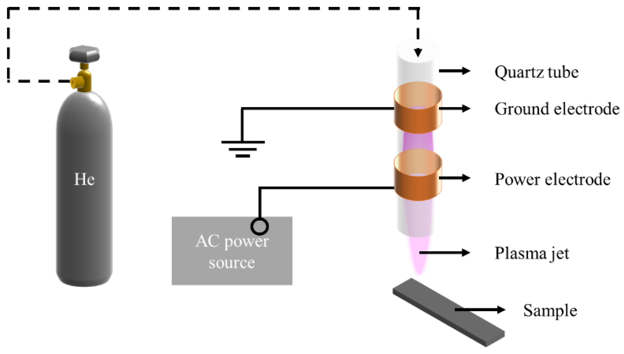
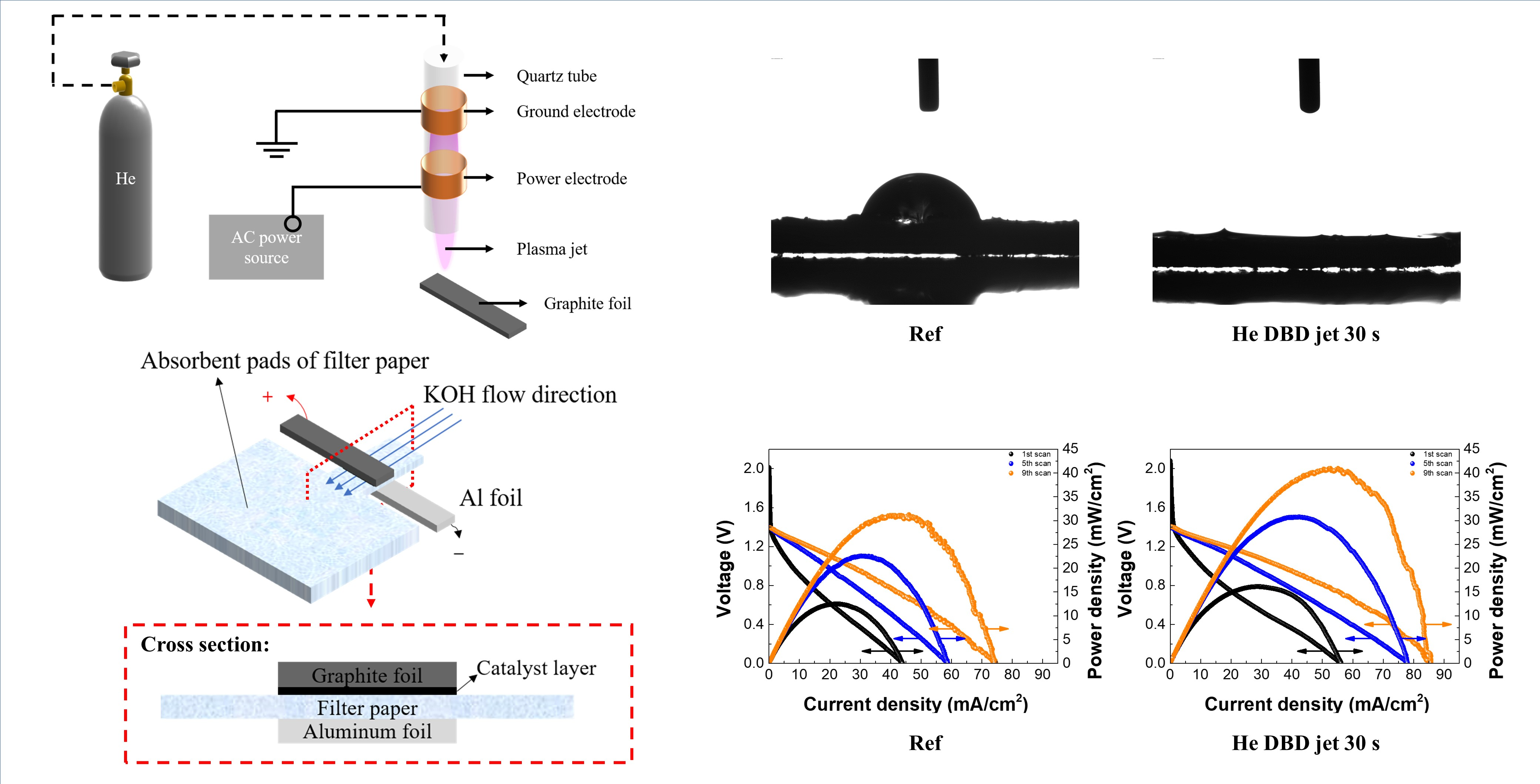
2.1. He DBD Jet
2.2. Materials
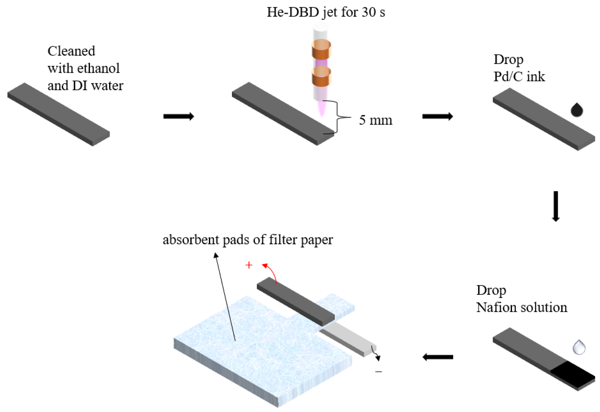
2.3. Fabrication of the Al-Air Battery
2.4. Characterization
3. Results
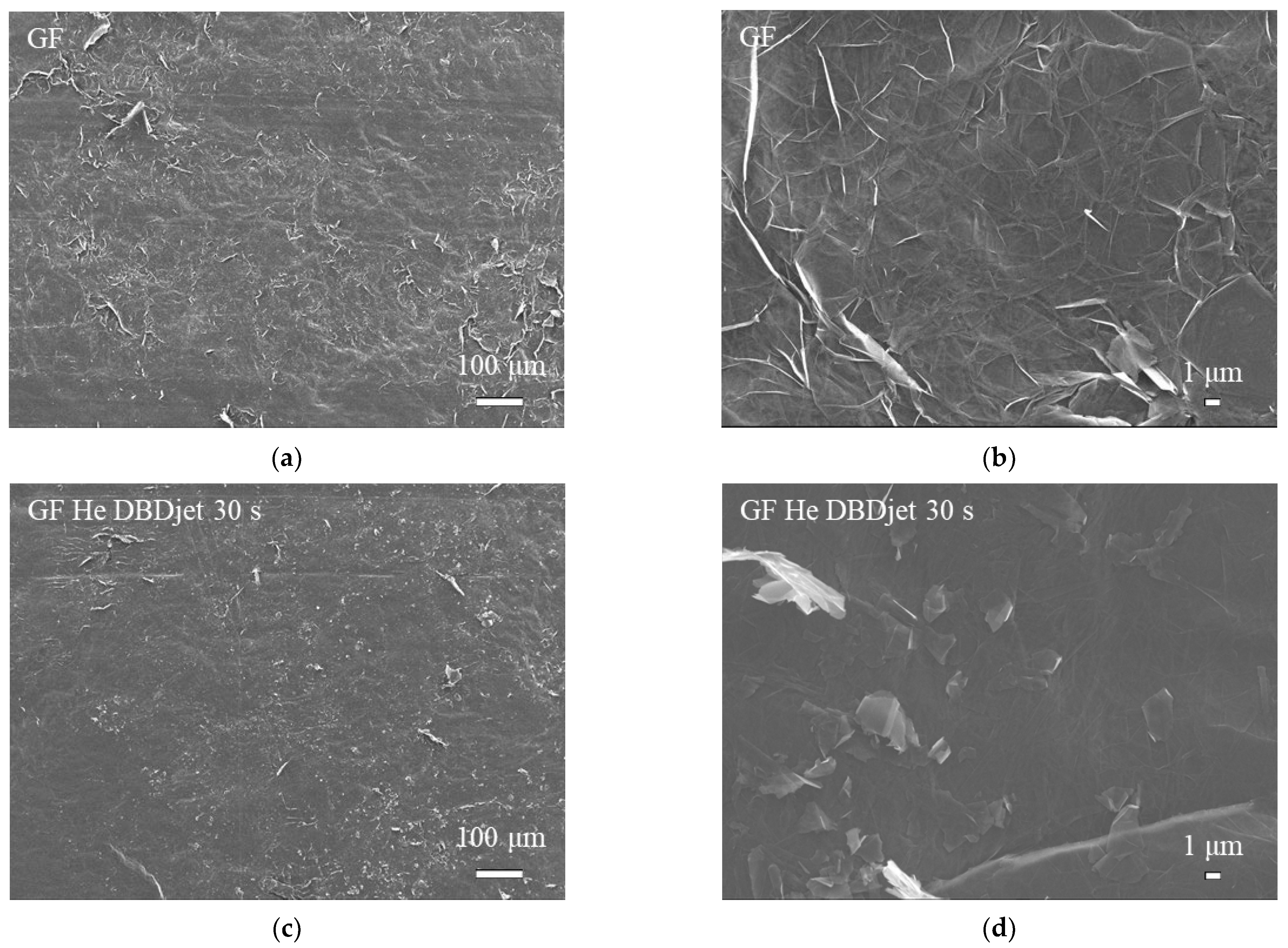
3.1. SEM Analysis
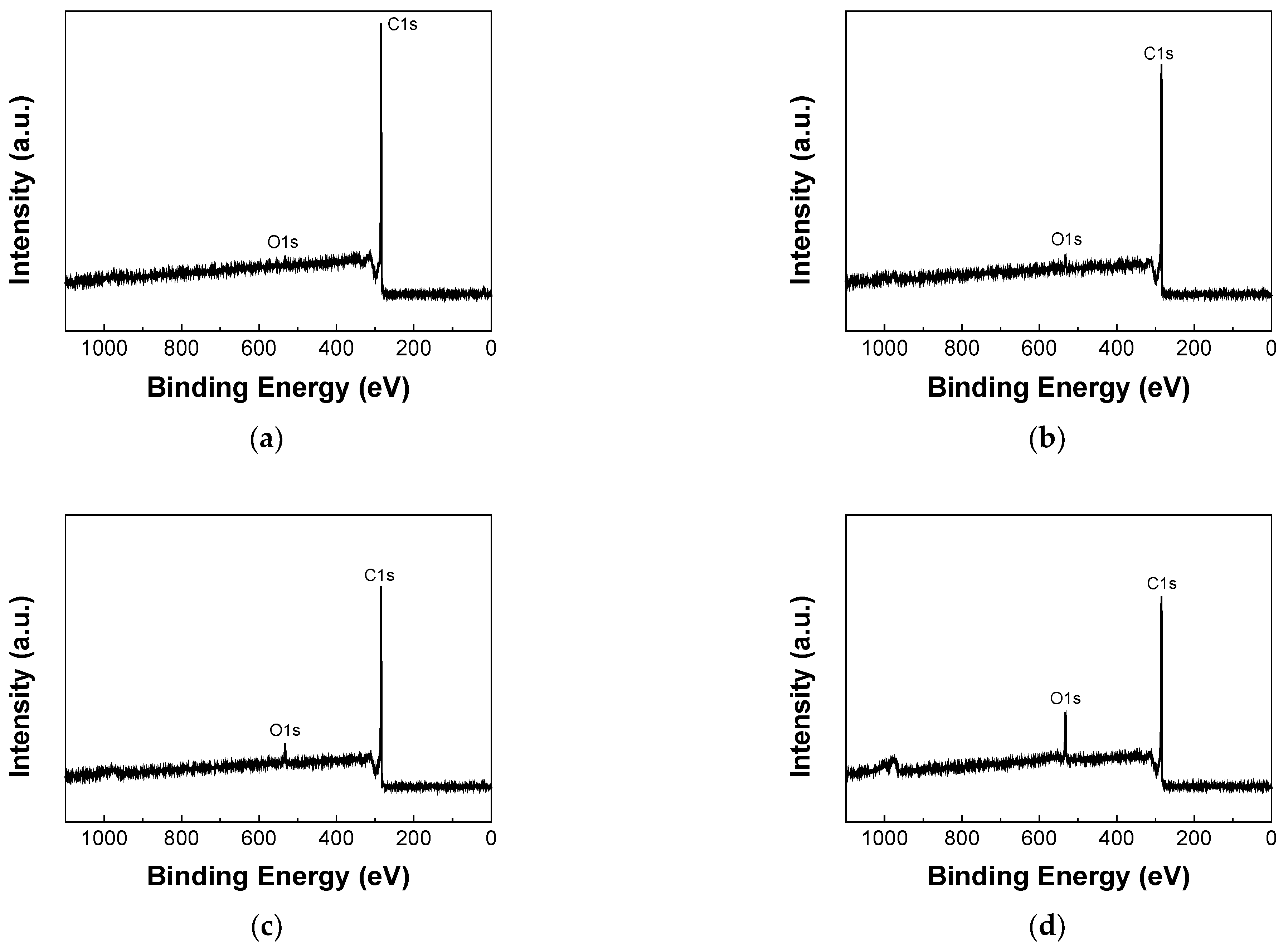
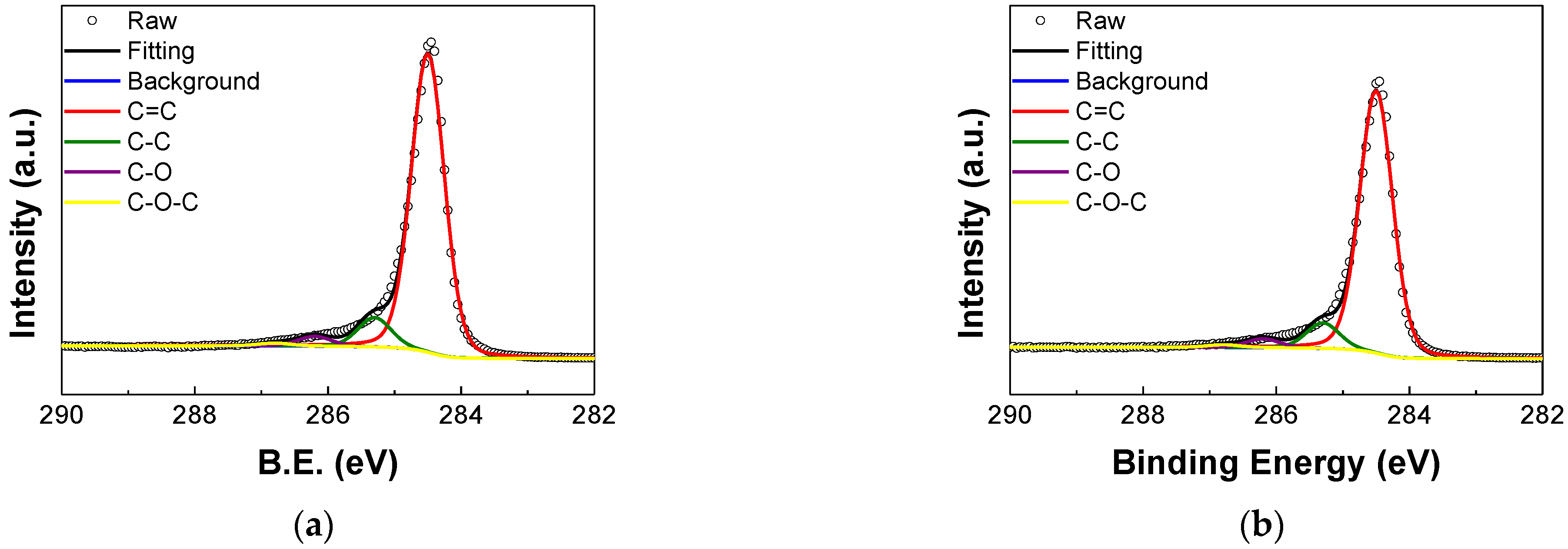
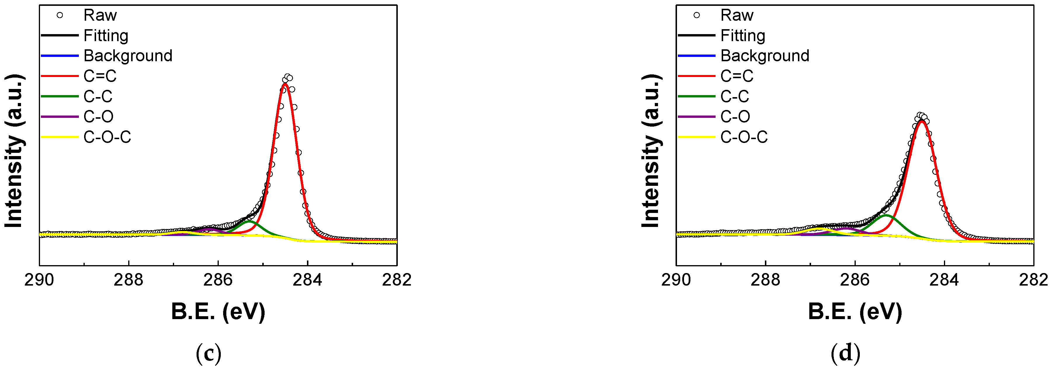
3.2. XPS Analysis
3.3. External Quantum Efficiency Analysis
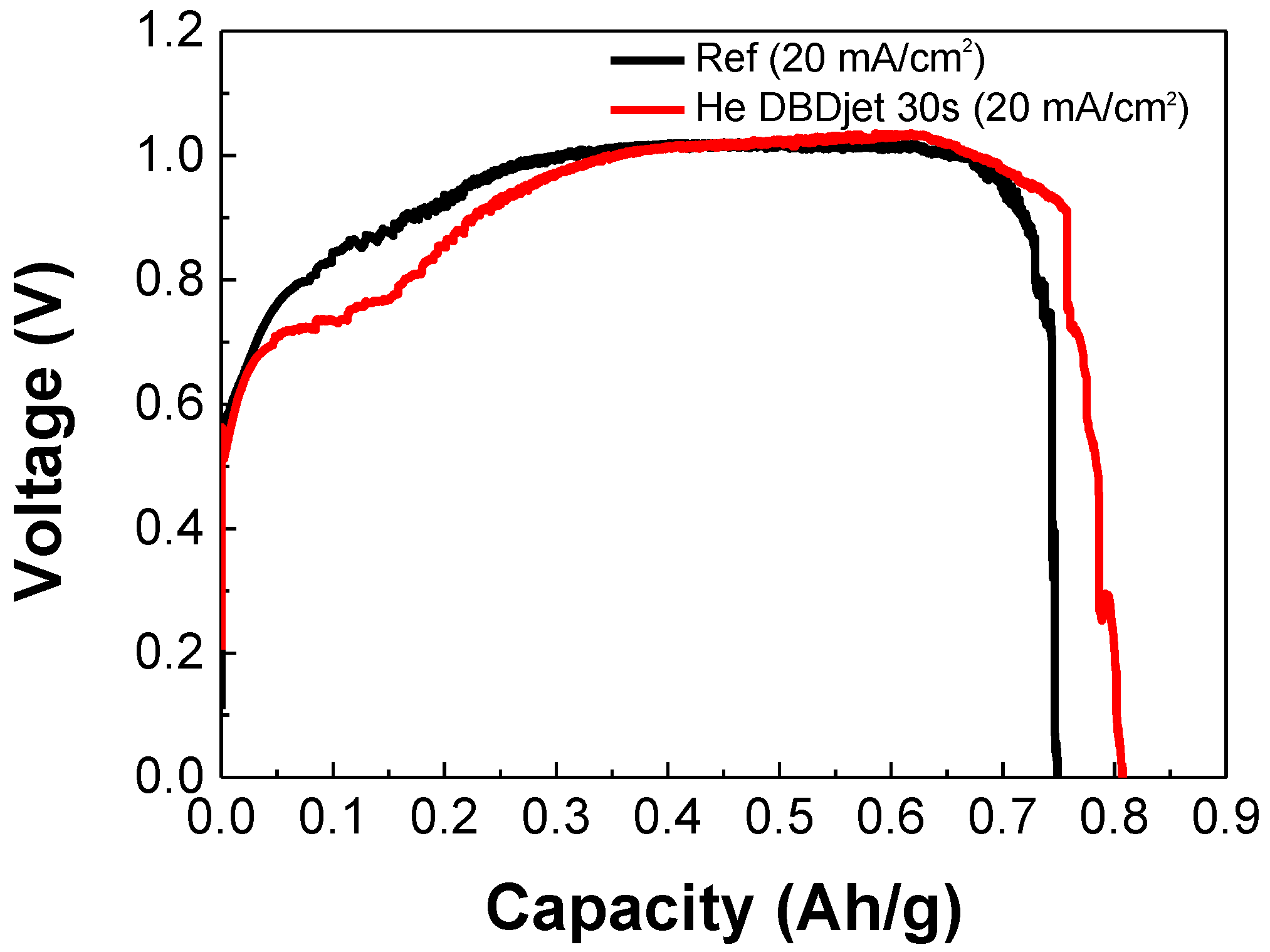
3.4. Electrochemical Performance of Paper-Based Al-Air Batteries
3.5. Electrochemical Impedance Spectroscopy Analysis
4. Conclusions
Supplementary Materials
Author Contributions
Funding
Institutional Review Board Statement
Informed Consent Statement
Data Availability Statement
Acknowledgments
Conflicts of Interest
References
- Douka, A.I.; Yang, H.; Huang, L.; Zaman, S.; Yue, T.; Guo, W.; You, B.; Xia, B.Y. Transition metal/carbon hybrids for oxygen electrocatalysis in rechargeable zinc-air batteries. EcoMat 2021, 3, e12067. [Google Scholar] [CrossRef]
- Wang, X.; Zhang, X.; Fu, G.; Tang, Y. Recent progress of electrospun porous carbon-based nanofibers for oxygen electrocatalysis. Mater. Today Energy 2021, 22, 100850. [Google Scholar] [CrossRef]
- Wu, S.; Zhang, Q.; Ma, J.; Sun, D.; Tang, Y.; Wang, H. Interfacial design of Al electrode for efficient aluminum-air batteries: Issues and advances. Mater. Today Energy 2020, 18, 100499. [Google Scholar] [CrossRef]
- Avoundjian, A.; Galvan, V.; Gomez, F.A. An inexpensive paper-based aluminum-air battery. Micromachines 2017, 8, 222. [Google Scholar] [CrossRef]
- Wang, Y.; Kwok, H.Y.; Pan, W.; Zhang, H.; Lu, X.; Leung, D.Y. Parametric study and optimization of a low-cost paper-based Al-air battery with corrosion inhibition ability. Appl. Energy 2019, 251, 113342. [Google Scholar] [CrossRef]
- Wang, Y.; Kwok, H.Y.; Pan, W.; Zhang, Y.; Zhang, H.; Lu, X.; Leung, D.Y. Combining Al-air battery with paper-making industry, a novel type of flexible primary battery technology. Electrochim. Acta 2019, 319, 947–957. [Google Scholar] [CrossRef]
- Teabnamang, P.; Kao-ian, W.; Nguyen, M.T.; Yonezawa, T.; Cheacharoen, R.; Kheawhom, S. High-capacity dual-electrolyte aluminum–air battery with circulating methanol anolyte. Energies 2020, 13, 2275. [Google Scholar] [CrossRef]
- Welch, C.; Mohammad, A.K.; Hosmane, N.S.; Zhang, L.; Cho, K.T. Effect of Aluminum Oxide on the Performance of Ionic Liquid-Based Aluminum–Air Battery. Energies 2020, 13, 2014. [Google Scholar] [CrossRef]
- Katsoufis, P.; Katsaiti, M.; Mourelas, C.; Andrade, T.S.; Dracopoulos, V.; Politis, C.; Avgouropoulos, G.; Lianos, P. Study of a thin film aluminum-air battery. Energies 2020, 13, 1447. [Google Scholar] [CrossRef]
- Zuo, Y.; Yu, Y.; Zuo, C.; Ning, C.; Liu, H.; Gu, Z.; Cao, Q.; Shen, C. Low-temperature performance of Al-air batteries. Energies 2019, 12, 612. [Google Scholar] [CrossRef]
- Mori, R. Recent developments for aluminum–air batteries. Electrochem. Energy Rev. 2020, 3, 344–369. [Google Scholar] [CrossRef]
- Salado, M.; Lizundia, E. Materials Today Energy. Mater. Today 2022, 28, 101064. [Google Scholar]
- Zhang, Y.; Liu, S.; Ji, Y.; Ma, J.; Yu, H. Emerging nonaqueous aluminum-ion batteries: Challenges, status, and perspectives. Adv. Mater. 2018, 30, 1706310. [Google Scholar] [CrossRef]
- Egan, D.; De León, C.P.; Wood, R.; Jones, R.; Stokes, K.; Walsh, F. Developments in electrode materials and electrolytes for aluminium–air batteries. J. Power Sources 2013, 236, 293–310. [Google Scholar] [CrossRef]
- Wu, S.; Zhang, Q.; Sun, D.; Luan, J.; Shi, H.; Hu, S.; Tang, Y.; Wang, H. Understanding the synergistic effect of alkyl polyglucoside and potassium stannate as advanced hybrid corrosion inhibitor for alkaline aluminum-air battery. Chem. Eng. J. 2020, 383, 123162. [Google Scholar] [CrossRef]
- Wang, Y.; Pan, W.; Kwok, H.Y.; Zhang, H.; Lu, X.; Leung, D.Y. Liquid-free Al-air batteries with paper-based gel electrolyte: A green energy technology for portable electronics. J. Power Sources 2019, 437, 226896. [Google Scholar] [CrossRef]
- Shen, L.-L.; Zhang, G.-R.; Biesalski, M.; Etzold, B.J. based microfluidic aluminum–air batteries: Toward next-generation miniaturized power supply. Lab A Chip 2019, 19, 3438–3447. [Google Scholar] [CrossRef]
- Anagri, A.; Zgheib, E.; Pulpytel, J.; Tran, T.M.; Alhussein, A.; Arefi-Khonsari, F. Nanoindentation characterization of nanocomposites coating based on graphene and siloxane matrix deposited by dielectric barrier discharge plasma. Surf. Interfaces 2022, 32, 102093. [Google Scholar] [CrossRef]
- Safari, R.; Sohbatzadeh, F.; Mohsenpour, T. Optical and electrical properties of N-DLC films deposited by atmospheric pressure DBD plasma: Effect of deposition time. Surf. Interfaces 2020, 21, 100795. [Google Scholar] [CrossRef]
- Armenise, V.; Fanelli, F.; Milella, A.; D’Accolti, L.; Uricchio, A.; Fracassi, F. Atmospheric pressure plasma treatment of polyurethane foams with He–O2 fed dielectric barrier discharges. Surf. Interfaces 2020, 20, 100600. [Google Scholar] [CrossRef]
- Klébert, S.; Tilajka, S.; Románszki, L.; Mohai, M.; Csiszár, E.; Károly, Z. Degradation phenomena on atmospheric air plasma treatment of polyester fabrics. Surf. Interfaces 2021, 22, 100826. [Google Scholar] [CrossRef]
- Krochmalny, K.; Pawlak-Kruczek, H.; Skoczylas, N.; Kudasik, M.; Gajda, A.; Gnatowska, R.; Serafin-Tkaczuk, M.; Czapka, T.; Jaiswal, A.K.; Arora, A. Use of Hydrothermal Carbonization and Cold Atmospheric Plasma for Surface Modification of Brewer’s Spent Grain and Activated Carbon. Energies 2022, 15, 4396. [Google Scholar] [CrossRef]
- Moreau, E. Airflow control by non-thermal plasma actuators. J. Phys. D Appl. Phys. 2007, 40, 605. [Google Scholar] [CrossRef]
- Eliasson, B.; Kogelschatz, U. Nonequilibrium volume plasma chemical processing. IEEE Trans. Plasma Sci. 1991, 19, 1063–1077. [Google Scholar] [CrossRef]
- Park, J.; Henins, I.; Herrmann, H.; Selwyn, G.; Jeong, J.; Hicks, R.; Shim, D.; Chang, C. An atmospheric pressure plasma source. Appl. Phys. Lett. 2000, 76, 288–290. [Google Scholar] [CrossRef]
- Tendero, C.; Tixier, C.; Tristant, P.; Desmaison, J.; Leprince, P. Atmospheric pressure plasmas: A review. Spectrochim. Acta Part B At. Spectrosc. 2006, 61, 2–30. [Google Scholar] [CrossRef]
- Tsai, J.-H.; Cheng, I.-C.; Hsu, C.-C.; Chueh, C.-C.; Chen, J.-Z. Feasibility study of atmospheric-pressure dielectric barrier discharge treatment on CH3NH3PbI3 films for inverted planar perovskite solar cells. Electrochim. Acta 2019, 293, 1–7. [Google Scholar] [CrossRef]
- Chen, Z.-C.; Cheng, Y.; Lin, C.-C.; Li, C.-S.; Hsu, C.-C.; Chen, J.-Z.; Wu, C.-I.; Cheng, I.-C. In-situ atmospheric-pressure dielectric barrier discharge plasma treated CH3NH3PbI3 for perovskite solar cells in regular architecture. Appl. Surf. Sci. 2019, 473, 468–475. [Google Scholar] [CrossRef]
- Li, T.-E.; Tsai, J.-H.; Cheng, I.-C.; Hsu, C.-C.; Chen, J.-Z. Atmospheric-pressure surface-diffusion dielectric-barrier discharge (SDDBD) plasma surface modification of PEDOT: PSS. Synth. Met. 2019, 256, 116114. [Google Scholar] [CrossRef]
- Lin, C.-I.; Tsai, J.-H.; Chen, J.-Z. Scanning atmospheric-pressure plasma jet treatment of nickel oxide with peak temperature of∼ 500 °C for fabricating p–i–n structure perovskite solar cells. RSC Adv. 2020, 10, 11166–11172. [Google Scholar] [CrossRef]
- Tsai, J.-H.; Cheng, I.-C.; Hsu, C.-C.; Chen, J.-Z. Low-temperature (<40 °C) atmospheric-pressure dielectric-barrier-discharge-jet treatment on nickel oxide for p–i–n structure perovskite solar cells. ACS Omega 2020, 5, 6082–6089. [Google Scholar] [CrossRef]
- Fan, C.-F.; Tsai, J.-H.; Liao, Y.-C.; Cheng, I.-C.; Hsu, C.-C.; Chen, J.-Z. Low temperature (<40 °C) atmospheric-pressure dielectric-barrier-discharge-jet (DBDjet) plasma treatment on jet-sprayed silver nanowires (AgNWs) electrodes for fully solution-processed nip structure perovskite solar cells. ECS J. Solid State Sci. Technol. 2020, 9, 055016. [Google Scholar] [CrossRef]
- Mallela, M.S.; Tsai, J.-H.; Huang, J.-Z.; Hsu, C.-C.; Chen, M.-H.; Wu, C.-I.; Chen, J.-Z.; Cheng, I.-C. Dielectric barrier discharge jet processed TiO2 nanoparticle layer for flexible perovskite solar cells. J. Phys. D Appl. Phys. 2021, 55, 034003. [Google Scholar] [CrossRef]
- Shih, C.-Y.; Huang, J.-Z.; Chen, M.-H.; Hsu, C.-C.; Wu, C.-I.; Cheng, I.-C.; Chen, J.-Z. The Influence of Helium Dielectric Barrier Discharge Jet (DBDjet) Plasma Treatment on Bathocuproine (BCP) in pin-Structure Perovskite Solar Cells. Polymers 2021, 13, 4020. [Google Scholar] [CrossRef]
- Liu, C.; Hung, C.-W.; Cheng, I.-C.; Hsu, C.-C.; Cheng, I.-C.; Chen, J.-Z. Dielectric barrier discharge plasma jet (DBDjet) processed reduced graphene oxide/polypyrrole/chitosan nanocomposite supercapacitors. Polymers 2021, 13, 3585. [Google Scholar] [CrossRef]
- Huang, W.; Ptasinska, S. Functionalization of graphene by atmospheric pressure plasma jet in air or H2O2 environments. Appl. Surf. Sci. 2016, 367, 160–166. [Google Scholar] [CrossRef]
- Solís-Fernández, P.; Paredes, J.; Cosío, A.; Martínez-Alonso, A.; Tascón, J. A comparison between physically and chemically driven etching in the oxidation of graphite surfaces. J. Colloid Interface Sci. 2010, 344, 451–459. [Google Scholar] [CrossRef]
- Ederer, J.; Janoš, P.; Ecorchard, P.; Tolasz, J.; Štengl, V.; Beneš, H.; Perchacz, M.; Pop-Georgievski, O. Determination of amino groups on functionalized graphene oxide for polyurethane nanomaterials: XPS quantitation vs. functional speciation. RSC Adv. 2017, 7, 12464–12473. [Google Scholar] [CrossRef]
- Song, Y.; Feng, D.-Y.; Liu, T.-Y.; Li, Y.; Liu, X.-X. Controlled partial-exfoliation of graphite foil and integration with MnO2 nanosheets for electrochemical capacitors. Nanoscale 2015, 7, 3581–3587. [Google Scholar] [CrossRef]
- Wen, H.; Liu, Z.; Qiao, J.; Chen, R.; Zhao, R.; Wu, J.; Qiao, G.; Yang, J. High energy efficiency and high power density aluminum-air flow battery. Int. J. Energy Res. 2020, 44, 7568–7579. [Google Scholar] [CrossRef]
- Mutlu, R.N.; Yazıcı, B. The behavior of chemical and electrochemical Ag deposition on FeNi-mesh cathodes in Al-air battery. Int. J. Energy Res. 2019, 43, 6256–6268. [Google Scholar] [CrossRef]
- Xu, L.; Fan, H.; Huang, L.; Xia, J.; Li, S.; Li, M.; Ding, H.; Huang, K. Chrysanthemum-derived N and S co-doped porous carbon for efficient oxygen reduction reaction and aluminum-air battery. Electrochim. Acta 2017, 239, 1–9. [Google Scholar] [CrossRef]
- Hou, X.; Zhang, Y.; Cui, C.; Lin, C.; Li, Y.; Bu, D.; Yan, G.; Liu, D.; Wu, Q.; Song, X.-M. Photo-assisted Al-air batteries based on gel-state electrolyte. J. Power Sources 2022, 533, 231377. [Google Scholar] [CrossRef]
- Xu, Y.; Zhao, Y.; Ren, J.; Zhang, Y.; Peng, H. An all-solid-state fiber-shaped aluminum–air battery with flexibility, stretchability, and high electrochemical performance. Angew. Chem. 2016, 128, 8111–8114. [Google Scholar] [CrossRef]
- Fu, X.; Jiang, G.; Wen, G.; Gao, R.; Li, S.; Li, M.; Zhu, J.; Zheng, Y.; Li, Z.; Hu, Y. Densely accessible Fe-Nx active sites decorated mesoporous-carbon-spheres for oxygen reduction towards high performance aluminum-air flow batteries. Appl. Catal. B Environ. 2021, 293, 120176. [Google Scholar] [CrossRef]
- Liu, X.; Zhang, P.; Xue, J.; Zhu, C.; Li, X.; Wang, Z. High energy efficiency of Al-based anodes for Al-air battery by simultaneous addition of Mn and Sb. Chem. Eng. J. 2021, 417, 128006. [Google Scholar] [CrossRef]


| % | C | O |
|---|---|---|
| No plasma treatment | 97.62 | 2.38 |
| He DBD jet 30 s | 96.64 | 3.36 |
| He DBD jet 1 min | 94.08 | 5.92 |
| He DBD jet 3 min | 88.04 | 11.96 |
| % | C=C | C–C | C–OH | C–O–C |
|---|---|---|---|---|
| No plasma treatment | 87.73 | 8.62 | 2.86 | 0.79 |
| He DBD jet 30 s | 87.66 | 8.51 | 2.93 | 0.90 |
| He DBD jet 1 min | 87.33 | 7.96 | 3.19 | 1.52 |
| He DBD jet 3 min | 77.87 | 13.58 | 4.43 | 4.12 |
Publisher’s Note: MDPI stays neutral with regard to jurisdictional claims in published maps and institutional affiliations. |
© 2022 by the authors. Licensee MDPI, Basel, Switzerland. This article is an open access article distributed under the terms and conditions of the Creative Commons Attribution (CC BY) license (https://creativecommons.org/licenses/by/4.0/).
Share and Cite
Shih, C.-Y.; Ni, I.-C.; Chan, C.-L.; Hsu, C.-C.; Wu, C.-I.; Cheng, I.-C.; Chen, J.-Z. Helium Dielectric Barrier Discharge Plasma Jet (DBD Jet)-Processed Graphite Foil as Current Collector for Paper-Based Fluidic Aluminum-Air Batteries. Energies 2022, 15, 5914. https://doi.org/10.3390/en15165914
Shih C-Y, Ni I-C, Chan C-L, Hsu C-C, Wu C-I, Cheng I-C, Chen J-Z. Helium Dielectric Barrier Discharge Plasma Jet (DBD Jet)-Processed Graphite Foil as Current Collector for Paper-Based Fluidic Aluminum-Air Batteries. Energies. 2022; 15(16):5914. https://doi.org/10.3390/en15165914
Chicago/Turabian StyleShih, Chung-Yueh, I-Chih Ni, Chih-Lin Chan, Cheng-Che Hsu, Chih-I Wu, I-Chun Cheng, and Jian-Zhang Chen. 2022. "Helium Dielectric Barrier Discharge Plasma Jet (DBD Jet)-Processed Graphite Foil as Current Collector for Paper-Based Fluidic Aluminum-Air Batteries" Energies 15, no. 16: 5914. https://doi.org/10.3390/en15165914
APA StyleShih, C.-Y., Ni, I.-C., Chan, C.-L., Hsu, C.-C., Wu, C.-I., Cheng, I.-C., & Chen, J.-Z. (2022). Helium Dielectric Barrier Discharge Plasma Jet (DBD Jet)-Processed Graphite Foil as Current Collector for Paper-Based Fluidic Aluminum-Air Batteries. Energies, 15(16), 5914. https://doi.org/10.3390/en15165914