Article

A π-Phase-Shifted Fiber Bragg Grating Partial Discharge Sensor toward Power Transformers

1
State Grid Ningxia Electric Power Co., Ltd., Electric Power Research Institute, Yinchuan 750011, China
2
State Key Laboratory of Alternate Electrical Power System with Renewable Energy Sources, North China Electric Power University, Beijing 102206, China
*
Author to whom correspondence should be addressed.
Energies 2022, 15(16), 5849; https://doi.org/10.3390/en15165849
Submission received: 20 June 2022 / Revised: 15 July 2022 / Accepted: 20 July 2022 / Published: 12 August 2022
(This article belongs to the Section F1: Electrical Power System)

Abstract

:
Partial discharge (PD) ultrasonic detection is an early sign of the insolation defects of power transformers. The early diagnosis of PD requires the high sensitivity and reliability of ultrasonic sensing systems. For this purpose, a reformative PD ultrasonic sensing system based on phase-shifted FBG (PS-FBG) was demonstrated. By using PS-FBG as the ultrasonic sensing unit, the ultrasonic sensing system improved the response to the ultrasonic signal and overcame the electromagnetic noise. To compensate for the influence of temperature change on the ultrasonic sensing system, an automatic wavelength scanning demodulating method was carried out. The wavelength spanning strategy was optimized based on the principle of cross-correlation, in order to quicken the spanning. A PD detection test in the transformer oil was conducted, and the result shows that PS-FBG was 17.5 times more sensitive than PZT. Because of the better ultrasonic response, the proposed system was able to achieve the early diagnosis of insolation faults in a power transformer.

1. Introduction

Power transformers play an important role in voltage conversion and power dispatching in a power system. With the large size and complex structure, insulation faults caused by gaps, bubbles, suspended conductive particles, and burrs are the main causes of transformer defects. Therefore, the early diagnosis of insolation faults of power transformers is essential to the security of the power grid [1].
Partial discharge (PD) is an early manifestation of early defects of power transformers [2,3,4]. Based on electromagnetic waves, ultrasonic waves, and other signals, PD can be measured indirectly [1,5]. The ultra-high frequency (UHF) method and ultrasonic method are the most common means of PD detection at present [6,7,8]. With the advantages of electromagnetic interference immunity and location capability, the ultrasonic method is more effective when compared to the UHF method.
At present, this relies on piezoelectric ceramic (PZT) sensors. On one hand, electromagnetic noise will be introduced into the sensing heads, amplifiers, and cables in the PZT sensing systems. On the other hand, the sensitivity of PZT is not high enough to achieve early fault warning [9,10].
As a measuring method of anti-electromagnetic interference, sensing technology has become an ideal measuring means for transformers. Thus far, ultrasonic sensors using optical fibers are coming into use in the field of power transformer monitoring [11]. Recently, many researchers have developed various measuring systems, among which there are both internal and external sensors for ultrasonic PD. The most extensive ultrasonic measuring systems are based on optical interference technology and fiber Bragg gratings (FBGs).
For the optical interference technology, both internal and external sensors have been designed for the ultrasonic detection of the PD transformer. Jiang J et al. achieved PD detection in a 72.5 kV defective bushing of a transformer by a well-designed Sagnac interferometer, and the sensor was installed on the surface of the conductor [12]. Their work proved the sensitivity and reliability of optical interference technology, but the external installation method increased the ultrasonic refraction path between the discharge point and measurement point. Zhou H Y et al. demonstrated an internal ultrasonic sensing system based on a Michelson interferometer, and the sensor was set into the transformer tank. The average detection limit of the interferometer was about 18.6% of the traditional PZT system, realizing a more sensitive detection of the PD ultrasonic signal [13]. Although optical interference technology has a sensitive response to ultrasonic, it is hard to realize multiplex measurements because of the interference structure.
FBGs are sensitive to strain, and are suitable for detecting ultrasonic signals. Made of optical fibers, the insulating material ensures the reliability of internal detection in the power transformer, which is the most outstanding advantage. Internal ultrasonic sensing ensures the high sensitivity of the PD detection, which leads to an earlier warning of the insolation faults of the power transformers [14,15,16,17]. An ultrasonic sensing system based on FBG and broadband laser has been described by Sarkar [18]. Nevertheless, the sensitivity of the FBG-based ultrasonic sensing system is not sufficient for PD detection. To improve the sensitivity, Orlando Frazão et al. demonstrated an ultrasonic sensing system using phase-shifted FBG (PS-FBG) rather than FBG, given its better resonance of the optical bandgap. S. E. U. Lima et al. applied PS-FBG into an ultrasonic sensing system. The system was aimed for the PD of the power transformer. The experimental results emphasized the sensitivity of PS-FBG [19]. Guo-ming MA et al. verified the sensitivity of internally installed PS-FBG, and developed a distributed detection method. Their work realized the positioning of PD in the transformer tank [20]. Previous research has shown that because of the special π-phase-shifted structure, phase-shifted fiber gratings have higher ultrasonic sensitivity for PD detection. However, none of them considered the cross-sensitivity of stress and temperature in their ultrasonic sensing systems.
The cross-sensitivity of stress and temperature will lead to the low response of the ultrasonic signal while the temperature changes. For traditional FBG sensing systems, the widely used method is to use another FBG completely free from stress as the reference. The reference FBG was put in the same temperature field as the sensing FBG. The change caused by the temperature was obtained by reference grating, and then compensation was made for the sensing FBG. Although the reference FBG has a simple principle and high compensation accuracy for low frequency parameters, the low frequency response makes it unsuitable for ultrasonic sensing.
In this paper, a π-phase-shifted FBG partial discharge sensor toward power transformers is demonstrated. The ultrasonic sensing system based on PS-FBG was sensitive enough for the internal PD detection of power transformers. To compensate for the temperature change during ultrasonic sensing, a demodulating method with direct wavelength scanning was put forward. The method was optimized based on the principle of cross-correlation. The PD detection test in the transformer oil was conducted, and the results show that PS-FBG was 5.7 times more sensitive than PZT.

2. Principle

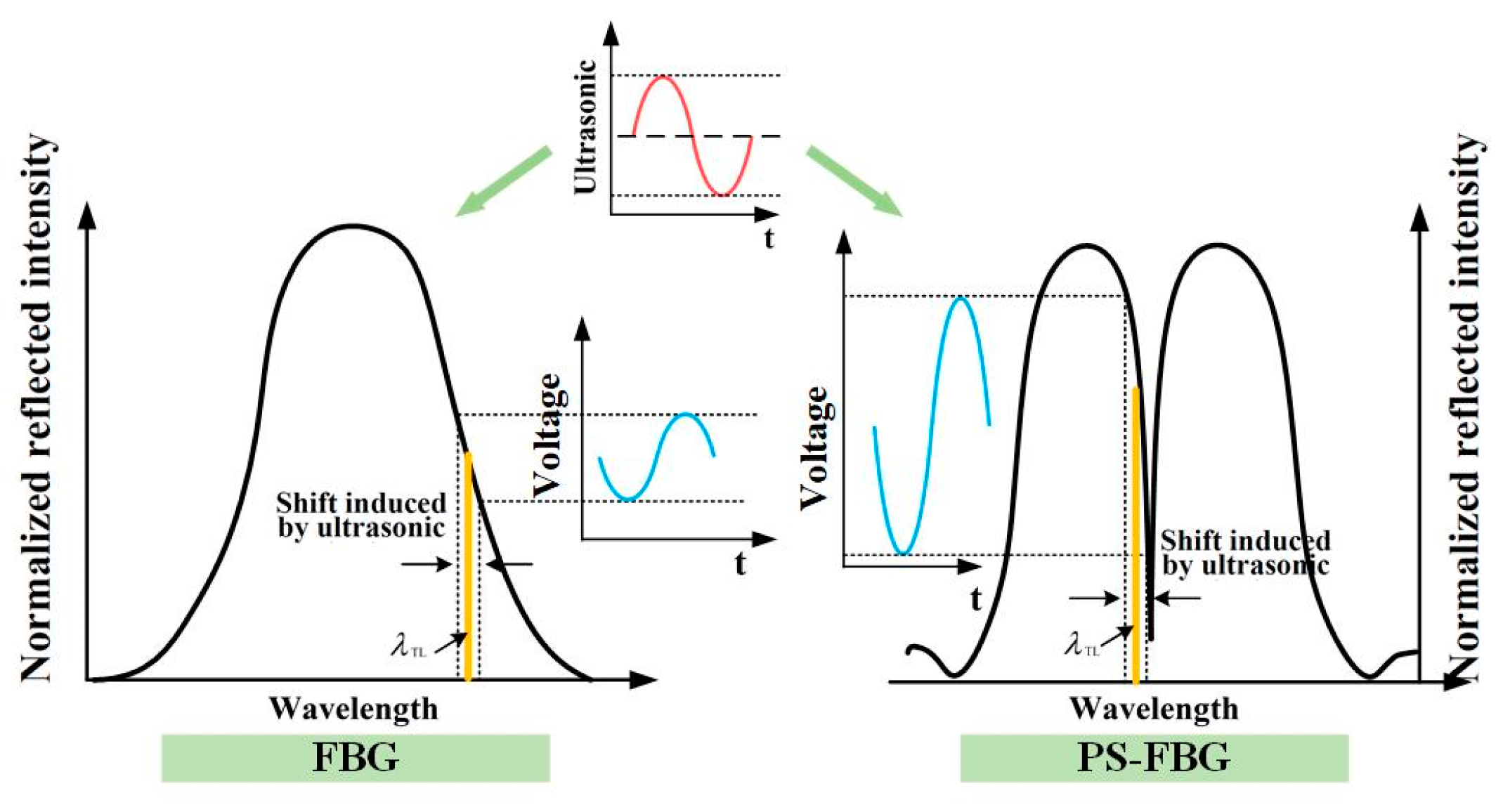
2.1. Ultrasonic Sensing Principle of PS-FBG

FBG is a permanent uniform grating periodically formed in the fiber core. FBG is equivalent to a narrow-band light mirror in the optical path. When the light source injects a broadband light into the optical fiber where the FBG is located, a narrowband light will be reflected. The wavelength of reflected light is called the Bragg wavelength λ B . Temperature change Δ T or strain change Δ ε can be conducive to shifting the Bragg wavelength, which can be expressed as [21].
Δ λ B λ B = α f + ξ Δ T + 1 p e Δ ε
where p e is the strain optic coefficient; ξ is the thermo-optic coefficient; and α f is the thermal expansion coefficient of the optical fiber. In the PD ultrasonic sensing system, FBG acts as a strain sensor. When the ultrasonic signal propagates to FBG, the changing strain affects the Bragg wavelength. The reflection spectrum of an ordinary FBG is shown on the left in Figure 1.
PS-FBG introduces a phase-shifted out-of-phase grating with a π-phase-shift in the particular part of the ordinary FBG, and forms more adjacent resonant peaks in the reflection spectrum [22]. As shown on the right in Figure 1, the two π phase-shifted gratings in PS-FBG opened a transmission window with an extremely narrow linewidth in the stopband, allowing for the light of the resonant wavelength to be injected into the stopband of the grating region, forming a transmission region in the reflection spectrum. The transmission window in the spectrum corresponds to the optical fiber Bragg wavelength, and when the phase shift increases or decreases by the same amount with π as the base point, the corresponding transmission window position is symmetrical with respect to the Bragg wavelength. The peak wavelength of the transmission window shifts from the short wavelength of the full spectral bandwidth to the long wavelength direction. In addition, the transmission window of the reflection spectrum of the π-phase-shifted fiber grating has high transmittance, is easy to be resolved and observed, and is not easily affected by spectral sidelobe, so it reliable for dynamic ultrasonic sensing.
In an ultrasonic sensing system, the main factor affecting the sensitivity of the ultrasonic signal is the slope of the spectral linear region, and the sensitivity of the ultrasonic signal is proportional to the spectral slope. As can be seen in Figure 1, for the same ultrasonic input signal, PS-FBG has a reflection spectrum with a larger slope than FBG. The larger slope leads to a larger light intensity change caused by the same intensity ultrasonic signal, which makes it more sensitive for ultrasonic detection.
In order to achieve ultrasonic sensing, an interrogation system with absolute accuracy is required, as shown in Figure 2. The interrogation system is mainly composed of a tunable laser and a high-speed photodetector. The narrow band laser source (TSL-710) emits a laser with the power of 6 mW. The narrow laser injects into the PS-FBG sensor through an optical circulator. The reflected light propagates into the three ports of the optical circulator, and then into the photodetector (PDA10CS). The electric signal is obtained and analyzed by the oscilloscope and signal processing part. The system is able to convert the wavelength vibration caused by the ultrasonic signal into the light intensity vibration, which improves the detection frequency band of the sensing system. The demodulation frequency can reach the MHz level.
With the PS-FBG and interrogation system described above, the wavelength vibration caused by the ultrasonic signal is converted into the light intensity vibration. The large slope in the reflection spectrum of PS-FBG improves the sensitivity of the ultrasonic detection, and ensures the capability of early insulation fault warning.

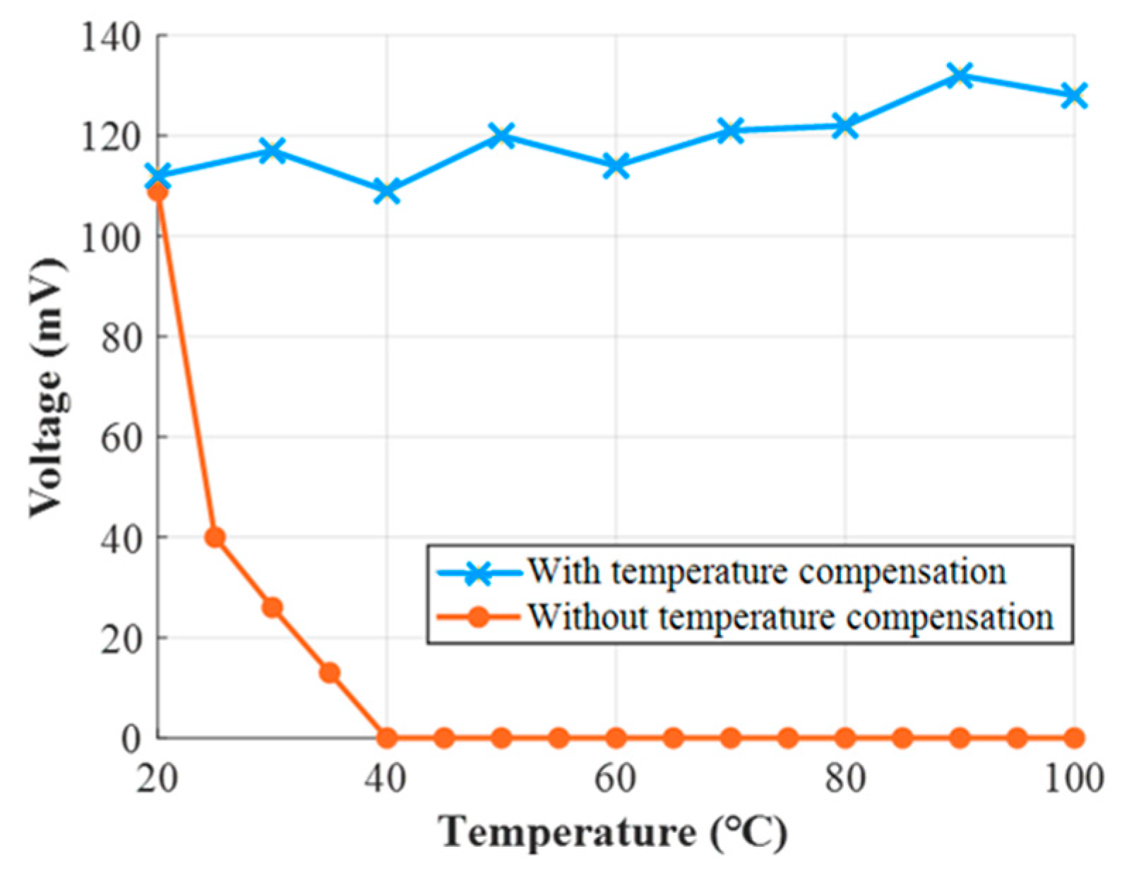
2.2. Solution of Stress and Temperature Cross-Sensitivity
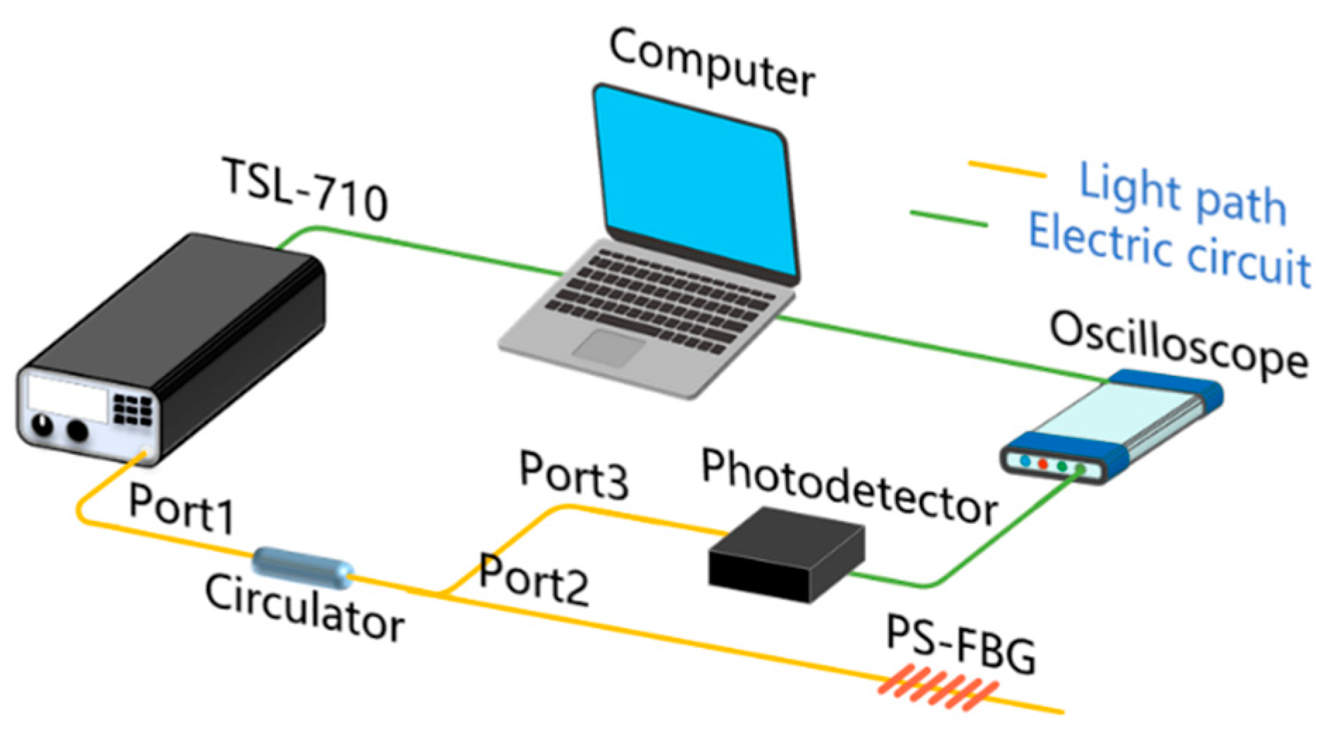
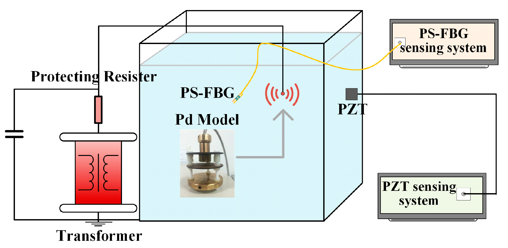
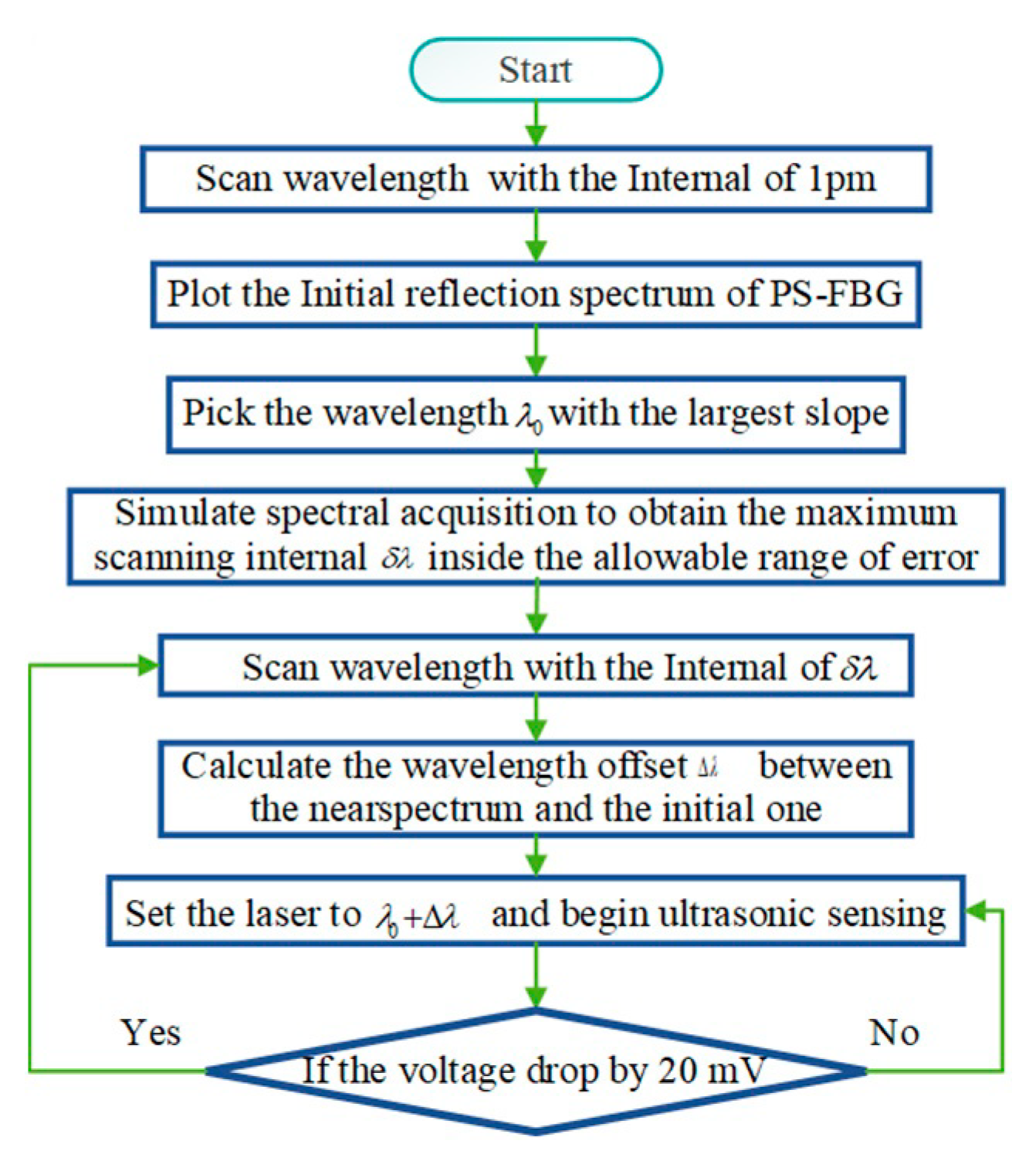
As shown in Equation (1), FBG is sensitive to temperature and ultrasonic stress at the same time, which is called the cross-sensitivity of stress and temperature. A PS-FBG has the same characteristics as an ordinary FBG, so when the temperature changes, the reflection spectrum of the fiber grating will drift, causing a mismatch between the spectrum of the PS-FBG and the laser wavelength. This mismatch will drive the working area to drift away from the linear slope of the spectrum, and this will decrease the sensitivity and linearity of ultrasonic sensing.
When the temperature changes, the light source can be reset by wavelength scanning. However, if the direct wavelength scanning method is used, the scanning time is long and it is difficult to ensure that the spectrum does not drift during this period. The available working band of a PS-FBG is 6~8 pm. In order to obtain the accurate working wavelength in such a narrow range, the scanning interval of the PS-FBG reflection spectrum was set to 1 pm, and the whole spanning range was 600 pm. Scanning took about 10 min, which is a long time and it is not easy to ensure that the spectrum does not drift during this period.
In order to make up for the mismatch between the injected laser wavelength and the spectrum of PS-FBG in time, we demonstrated a control system to realize the automatic wavelength scanning of the laser source and determine the best working wavelength, as shown in Figure 3. To improve the efficiency of determining the optimal working wavelength of the system, we optimized the wavelength spanning strategy using the cross-correlation principle. The definition of the cross-correlation function is shown in Equation (2):
C p q ( m ) = i = N N p ( n ) q ( n + m )
The formula indicates that the value at time C p q ( m ) is equal to the result of the multiplication and addition of two sequences after p ( n ) is kept fixed and q ( n ) moves to the left as the C p q ( m ) sampling periods are moved to the left. It reflects the degree to which the two sequences match each other in different relative positions [23].
In the temperature compensation, the main purpose of the cross-correlation algorithm is to obtain the wavelength drift of the PS-FBG reflection spectrum quickly. The maximum allowable wavelength scanning interval is calculated by a reflection spectrum span greater than 1 pm, and the reflection spectrum at a known 1 pm interval at a given temperature. The specific algorithm is as follows:
First, scan the above two spectral data, that is, the spectrum of the 1 pm interval p ( λ ) , and then scan the spectrum after wavelength drift q ( λ ) . Finally, calculate the correlation degree C p q ( λ j ) of the two reflectance spectra of PS-FBG at different temperatures according to the cross-correlation formula C p q ( λ j ) = i = N N p ( λ i ) q ( λ i + λ j ) .
According to the nature of cross-correlation, when the two spectra coincide, the degree of cross-correlation C p q ( λ j ) reaches the maximum, and the calculated wavelength shift of the two spectra λ j can be demodulated from the corresponding wavelength coordinates when C p q ( λ j ) reaches the maximum. Because the wavelength scanning interval is larger than 1 pm, there must be an error between the calculated wavelength drift and the actual wavelength drift. In practical calculation, it is necessary to obtain the corresponding errors of multiple groups of different wavelength scanning intervals under the set different wavelength drifts, and then analyze the maximum scanning interval under the allowable error in order to improve the scanning efficiency. What needs to be explained in Figure 3 is that 1 pm is the minimum adjustment range of the adjustable light source, and 20 mV is the lower limit of reliable ultrasonic demodulation.
This method does not need a reference grating. It can effectively ensure that the light source works at the best wavelength, ensure the sensitivity of the system, and avoid the problems caused by the introduction of reference gratings.

3. Experiment

Before the PD detection, a temperature compensation experiment was conducted to verify the effect of the cross-correlation wavelength scanning of PS-FBG ultrasonic testing system. The dependence of the reflection coefficient on the wavelength of the PS-FBG we used is shown in Figure 4. The linear working region of the reflection spectrum was only 6 pm, which means a sensitive response to ultrasonic signals. The sensing PS-FBG was heated by a heating plate. At different temperatures, the best working wavelength of the light source was redetermined, and the ultrasonic signals with specific frequencies and amplitudes were detected.
During the experiment, the efficiency of the wavelength determination was significantly improved. The relation curves between the different temperatures and the ultrasonic testing amplitudes with and without temperature compensation measures are shown in Figure 5. When there was no temperature compensation, the ultrasonic detection amplitude decreased to 0 mV with the increase in temperature. When the temperature compensation was carried out, the ultrasonic signal was able to be detected at all temperatures, where the amplitude varied between 109 and 132 mV. By analyzing and comparing the amplitudes of the ultrasonic signals measured at different temperatures, the temperature compensation effect of the system was determined.
The cross-correlation wavelength scanning temperature compensation of the PS-FBG ultrasonic sensing system can keep the ultrasonic detection amplitude of the system at a high level, which ensures the detection sensitivity of the system and has good feasibility and effectiveness.
In order to figure out the feasibility of PD detection in a power transformer, the ultrasonic detection in oil was carried out. The layout of the experiment is shown in Figure 6. The detection sensitivity of the PS-FBG sensor and traditional PZT sensor were compared and analyzed. During the test, the partial discharge model in oil needed to be adjusted to ensure that the distance between the two sensors and the partial discharge source was equal.
The PZT and PS-FBG sensors, PZT sensor model R15, had a resonant frequency of 146.5 kHz. The sensor cannot be immersed in oil for detection, so it was arranged in the way of a traditional PZT to detect the partial discharge of the transformer, smeared with Vaseline as a coupling agent, and affixed onto the outer shell of the fuel tank. The PS-FBG sensor is a π-phase-shifted fiber grating. Because of its excellent insulation performance and strong environmental adaptability, the PS-FBG sensor was directly arranged in the fuel tank through the self-made device and set on the shell of the fuel tank through the Vaseline coupling agent for a comparison with the traditional PZT.
In the experiment, when the voltage applied by the suspension model was about 28 kV, a discharge capacity of 1000~2500 pC occurred. The comparison test was carried out between PS-FBG built-in oil and the PZT sensor, and the detection results were collected by each sensor six times. The PS-FBG was affixed to the outer wall of the oil tank and compared with the PZT sensor, and each sensor collected the test results six times. Because the discharge capacity of each suspension model was different, the multiple relationships between the detection results of PS-FBG and PZT were calculated, and the average value of six times was taken as the result. The amplitude data of the test results and the calculated results are shown in Table 1. A comparison was made between the PS-FBG built-in oil and the PZT sensor. A group of typical signals is shown in Figure 7. The results showed that for suspended discharge, the detection sensitivity of ultrasonic sensor system in PS-FBG built-in oil was about 17.5 times better than the PZT sensor.

4. Conclusions

This paper demonstrated a π-phase-shifted FBG partial discharge sensor toward power transformers. With a phase shift of π in the specific part of the grating, PS-FBG showed a reflection spectrum with a larger slope, leading to a larger light intensity change caused by the same intensity ultrasonic signal. To compensate for the temperature change in the high-frequency ultrasonic sensing system, a demodulating method was carried out with automatic wavelength scanning. The wavelength spanning strategy was optimized based on the principle of cross-correlation, in order to quicken the spanning. The cross-correlation wavelength scanning temperature compensation of the PS-FBG ultrasonic sensing system can keep the ultrasonic detection amplitude of the system at a high level, which ensures the detection sensitivity of the system and has good feasibility and effectiveness. A PD detection test in transformer oil was conducted, and results showed that PS-FBG was 17.5 times more sensitive than PZT. Because of the better ultrasonic response, the proposed system was able to achieve the early diagnosis of insolation faults in a power transformer.

Author Contributions

Conceptualization, W.L.; Methodology, T.T.; Software, R.S.; Formal analysis, X.L.; Investigation, Y.L.; Data curation, N.H.; Writing—original draft preparation, S.W.; Writing—review and editing, G.M.; Visualization, Y.M.; Supervision, X.Z. All authors have read and agreed to the published version of the manuscript.

Funding

This research was funded by the Ningxia Natural Science Foundation, grant number 2021AAC03500.

Data Availability Statement

Not applicable.

Conflicts of Interest

The authors declare no conflict of interest.

References

  1. Li, S.; Li, J. Condition monitoring and diagnosis of power equipment: Review and prospective. High Volt. 2017, 2, 82–91. [Google Scholar] [CrossRef]
  2. Ma, G.; Wang, Y.; Qin, W.; Zhou, H.; Yan, C.; Jiang, J.; Ju, Y. Optical sensors for power transformer monitoring: A review. High Volt. 2021, 6, 367–386. [Google Scholar] [CrossRef]
  3. Markalous, S.M.; Tenbohlen, S.; Feser, K. Detection and location of partial discharges in power transformers using acoustic and electromagnetic signals. IEEE Trans. Dielectr. Electr. Insul. 2008, 15, 1576–1583. [Google Scholar] [CrossRef]
  4. Li, C.-R.; Ma, G.-M.; Qi, B.; Zhang, G.-J.; Su, Q. Condition monitoring and diagnosis of high-voltage equipment in China-recent progress. IEEE Electr. Insul. Mag. 2013, 29, 71–78. [Google Scholar] [CrossRef]
  5. IEEE Std C57.127-2007 (Revision of IEEE Std C57.127-2000); International Standard: IEEE Guide for the Detection and Location of Acoustic Emissions from Partial Discharges in Oil-Immersed Power Transformers and Reactors. IEEE: Manhattan, NY, USA, 2007; pp. c1–c47.
  6. Lundgaard, L.E. Partial discharge. XIII. Acoustic partial discharge detection-fundamental considerations. IEEE Electr. Insul. Mag. 1992, 8, 25–31. [Google Scholar] [CrossRef]
  7. Lundgaard, L. Partial discharge. XIV. Acoustic partial discharge detection-practical application. IEEE Electr. Insul. Mag. 1992, 8, 34–43. [Google Scholar] [CrossRef]
  8. Judd, M.D.; Li, Y.; Hunter, I.B.B. Partial discharge monitoring of power transformers using UHF sensors. Part I: Sensors and signal interpretation. IEEE Electr. Insul. Mag. 2005, 21, 5–14. [Google Scholar] [CrossRef]
  9. Zheng, S.; Li, C.; Tang, Z.; Chang, W.; He, M. Location of PDs inside transformer windings using UHF methods. IEEE Trans. Dielectr. Electr. Insul. 2014, 21, 386–393. [Google Scholar] [CrossRef]
  10. Cui, H.; Denghua, L. Research on Electromagnetic Interference Resistance of Piezoelectric Vibration Acceleration Sensor. Ferroelectrics 2014, 460, 82–97. [Google Scholar] [CrossRef]
  11. N’cho, J.S.; Fofana, I. Review of fiber optic diagnostic techniques for power transformers. Energies 2020, 13, 1789. [Google Scholar] [CrossRef]
  12. Jiang, J.; Song, Y.; Wang, K.; Lu, Y.; Li, J.; Ranjan, P.; Zhang, C. Partial discharge detection and sensitivity improvement for bushing based on optical interference technique. IEEE Trans. Power Deliv. 2021. [Google Scholar] [CrossRef]
  13. Zhou, H.Y.; Ma, G.M.; Zhang, M.; Zhang, H.C.; Li, C.R. A high sensitivity optical fiber interferometer sensor for acoustic emission detection of partial discharge in power transformer. IEEE Sens. J. 2019, 21, 24–32. [Google Scholar] [CrossRef]
  14. Sahota, J.K.; Gupta, N.; Dhawan, D. Fiber Bragg grating sensors for monitoring of physical parameters: A comprehensive review. Opt. Eng. 2020, 59, 060901. [Google Scholar] [CrossRef]
  15. Ma, G.M.; Jiang, J.; Mu, R.D.; Li, C.R.; Luo, Y.T. High Sensitive FBG Sensor for Equivalent Salt Deposit Density Measurement. IEEE Photonics Technol. Lett. 2015, 27, 177–180. [Google Scholar] [CrossRef]
  16. Jiang, J.; Ma, G.M.; Li, C.R.; Song, H.T.; Luo, Y.T.; Wang, H.B. Highly Sensitive Dissolved Hydrogen Sensor Based on Side-Polished Fiber Bragg Grating. IEEE Photonics Technol. Lett. 2015, 27, 1453–1456. [Google Scholar] [CrossRef]
  17. Lima, S.E.U.; Frazao, O.; Farias, R.G.; Araujo, F.M.; Ferreira, L.A.; Santos, J.L.; Miranda, V. Mandrel-Based Fiber-Optic Sensors for Acoustic Detection of Partial Discharges—A Proof of Concept. IEEE Trans. Power Deliv. 2010, 25, 2526–2534. [Google Scholar] [CrossRef]
  18. Sarkar, B.; Mishra, D.K.; Koley, C.; Roy, N.K.; Biswas, P. Intensity-Modulated Fiber Bragg Grating Sensor for Detection of Partial Discharges Inside High-Voltage Apparatus. IEEE Sens. J. 2016, 16, 7950–7957. [Google Scholar] [CrossRef]
  19. Lima, S.E.U.; Farias, R.G.; Araújo, F.M.; Ferreira, L.A.; Santos, J.L.; Miranda, V.; Frazão, O. Fiber laser sensor based on a phase-shifted chirped grating for acoustic sensing of partial discharges. Photonic Sens. 2012, 3, 44–51. [Google Scholar] [CrossRef]
  20. Ma, G.M.; Zhou, H.Y.; Shi, C.; Li, Y.B.; Zhang, Q.; Li, C.R.; Zheng, Q. Distributed partial discharge detection in a power transformer based on phase-shifted FBG. IEEE Sens. J. 2018, 18, 2788–2795. [Google Scholar] [CrossRef]
  21. Kersey, A.D.; Davis, M.A.; Patrick, H.J.; LeBlanc, M.; Koo, K.P.; Askins, C.G.; Friebele, E.J. Fiber grating sensors. J. Lightwave Technol. 1997, 15, 1442–1463. [Google Scholar] [CrossRef]
  22. Agrawal, G.P.; Radic, S. Phase-shifted fiber Bragg gratings and their application for wavelength demultiplexing. IEEE Photonics Technol. Lett. 1994, 6, 995–997. [Google Scholar] [CrossRef]
  23. Helleseth, T. Some results about the cross-correlation function between two maximal linear sequences. Discret. Math. 1976, 16, 209–232. [Google Scholar] [CrossRef]
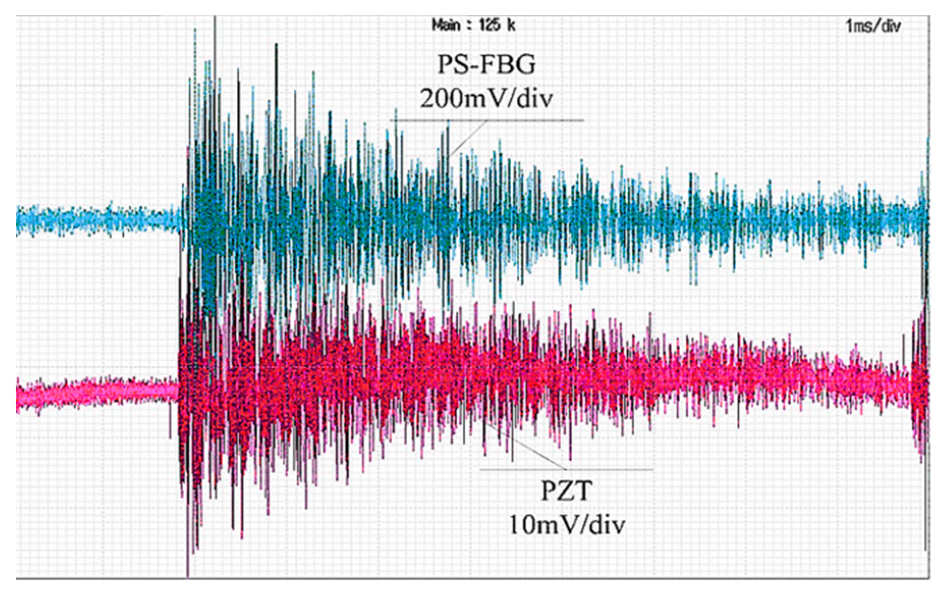
Figure 1. A comparison of the ultrasonic sensing process between the FBG and the π-phase-shifted FBG.
Energies 15 05849 g001
Figure 2. The interrogation system of phase-shifted FBG ultrasonic sensing.
Energies 15 05849 g002
Figure 3. The scheme of the cross-correlation wavelength scanning.
Energies 15 05849 g003
Figure 4. The scheme of the cross-correlation wavelength scanning.
Energies 15 05849 g004
Figure 5. A comparation of the temperature compensation.
Energies 15 05849 g005
Figure 6. A schematic diagram of the ultrasonic detection for the partial discharge detection of the transformer.
Energies 15 05849 g006
Figure 7. The test results of PS-FBG in oil and the PZT sensor.
Energies 15 05849 g007
Table 1. The PD detection amplitude of the PS-FBG and PZT sensors.
Times123456
Voltage/mV
PS-FBG935156195012069321058
PZT637265695455
Multiple14.821.914.617.51719.2
Average multiple17.5
Publisher’s Note: MDPI stays neutral with regard to jurisdictional claims in published maps and institutional affiliations.

