Article

Investigation of the Effectiveness of a New Backfilling Method: “Multi-Arch Pier-Column”

1
College of Energy and Mining Engineering, Shandong University of Science and Technology, Qingdao 266590, China
2
College of Transportation, Shandong University of Science and Technology, Qingdao 266590, China
*
Authors to whom correspondence should be addressed.
Energies 2022, 15(16), 5845; https://doi.org/10.3390/en15165845
Submission received: 7 July 2022 / Revised: 4 August 2022 / Accepted: 9 August 2022 / Published: 11 August 2022

Abstract

:
Owing to the shortcomings of blindness and inaccuracy when backfilling in goafs and based on the key stratum theory, we propose the “multi-arch pier-column” backfilling method. This method involves drilling holes at specific locations on the surface to inject filling and slurry materials into the goaf and separation area under the key stratum. This allows the broken gangue to be cemented to form a stone body, to improve its overall strength. This process, along with filling in the separation area under the key stratum, ensures that the key stratum does not break, forming a joint medium of “separation area filling body + backfilled pier-columns + key stratum + coal column”, which prevents new subsidence on the surface layer. Using the Gaojialiang coal mine as an example, the effects of the proposed method on controlling surface subsidence were determined using a numerical simulation based on FLAC3D simulation software. The results indicate that this method can effectively control the key stratum and ensure that the surface subsidence is within a safe range. The multi-arch pier-column backfilling method utilises the self-bearing capacity of the overburden structure and greatly reduces the backfilling workload and the cost of backfilling for controlling surface subsidence. At present, the multi-arch pier-column system of the new backfill method is an unexplored and new area of research.

1. Introduction

During mining activities, if the goaf is left behind it will lead to a series of secondary disasters, such as groundwater depletion, surface collapse, house cracking, road cracking, ecological deterioration, and it can destroy the balance of the geological environment in the coal goaf [1,2,3,4,5,6]. The management of the goaf and its secondary disasters is an extremely complicated problem [7,8]. After the underground ore body is extracted, the original mechanical equilibrium state of the ore body endowment is destroyed, and gravity causes fractures and interlayer slip to be generated between the rock layers. Groundwater penetrates into the goaf through the fractures, which accelerates the damage and eventually causes rock layer misalignment and surface subsidence, forming a mine collapse area. Therefore, it is critical to know the range and degree of the influence of the underground goaf on the overlying strata, for mining subsidence management.
At present, the main technical methods used to control overburden and surface movement are coordinated, partial, and backfill mining. Coordinated mining involves two or more adjacent working faces which are used to maintain a certain relationship in time and space to partially offset surface movement deformation. The area can be divided into two seams with coordinated mining and symmetrical mining of multiple working faces of the same coal seam. Partial mining refers to methods that effectively control overburden and surface movement, primarily including strip mining, thickness-limited mining, and room and pillar mining [9]. The essence of backfill mining is replacing the coal with backfill material. Based on the backfill volume and the proportion of the backfill area to the extracted coal seam, backfill mining methods can be divided into total or partial backfill. Total backfill mining means that after the coal seam has been mined, the entire goaf is filled before the roof falls, and the backfilling volume and range are roughly the same as the mined out coal volume. This method completely relies on filling the body of the goaf to support the overlying rock layer and control mining subsidence [10,11,12,13,14,15,16].
Partial backfill mining is similar to total backfilling; however, the backfilling volume and range are only a part of the extracted coal volume and only fill part of the separation area of the goaf and the roof fall area [4,17,18,19,20,21]. This method relies on the overburden key stratum structure, filling body, and part of the coal column to support the overburden rock and control mining subsidence. Based on the different backfilling locations, partial backfilling can be subdivided into three methods: backfilling of paste strips in the mining void area, isolated slurry backfilling in the overburden delamination zone, and slurry backfilling in the strip mining subsidence area [4,22,23,24]. Paste strip backfilling uses a paste material to fill part of the space in the goaf before the roof falls after the coal seam has been mined, to construct interphase backfilling strips, which are used to support the overlying rock [21]. Overburden offset slurry backfilling uses the offset cavity formed in the overburden during rock movement, and fills the offset cavity with foreign material from the borehole to support the overburden and slow the propagation of the overburden movement to the surface [25]. In strip mining, slurry backfilling is used to fill the broken gangue in the extraction strip by drilling holes on the surface or underground to fill the broken gangue in the extraction strip, reinforce the broken rock, and allow the collapsed extraction strip to bear the load [26]. It effectively reduces the load and reduces the compression deformation on the coal column and the rock column above it within a certain range, slowing the propagation of overburden rock movement to the surface. The full backfilling injected slurry method has many advantages, such as being economical, simple, and reliable, making it an effective goaf control measure. However, it is difficult to construct, expensive, and has poor operational safety. Partial backfilling is a good solution to the problem of high cost and high backfilling volume. In partial backfilling, the “backfilling body-key stratum-coal pillar” is formed as a common load-bearing structure to support the overburden load.
This thesis, based on a summary of previous experience, proposes to inject slurry into the goaf from the surface, thus forming a pier structure and a “multi-arch pier-column” backfilling support structure between the pier and key stratum overlying the goaf. The most critical factor of this structure is to choose the corresponding backfilling method according to the specific overburden breaking situation of the specific goaf, and to target the precise backfilling of the goaf.

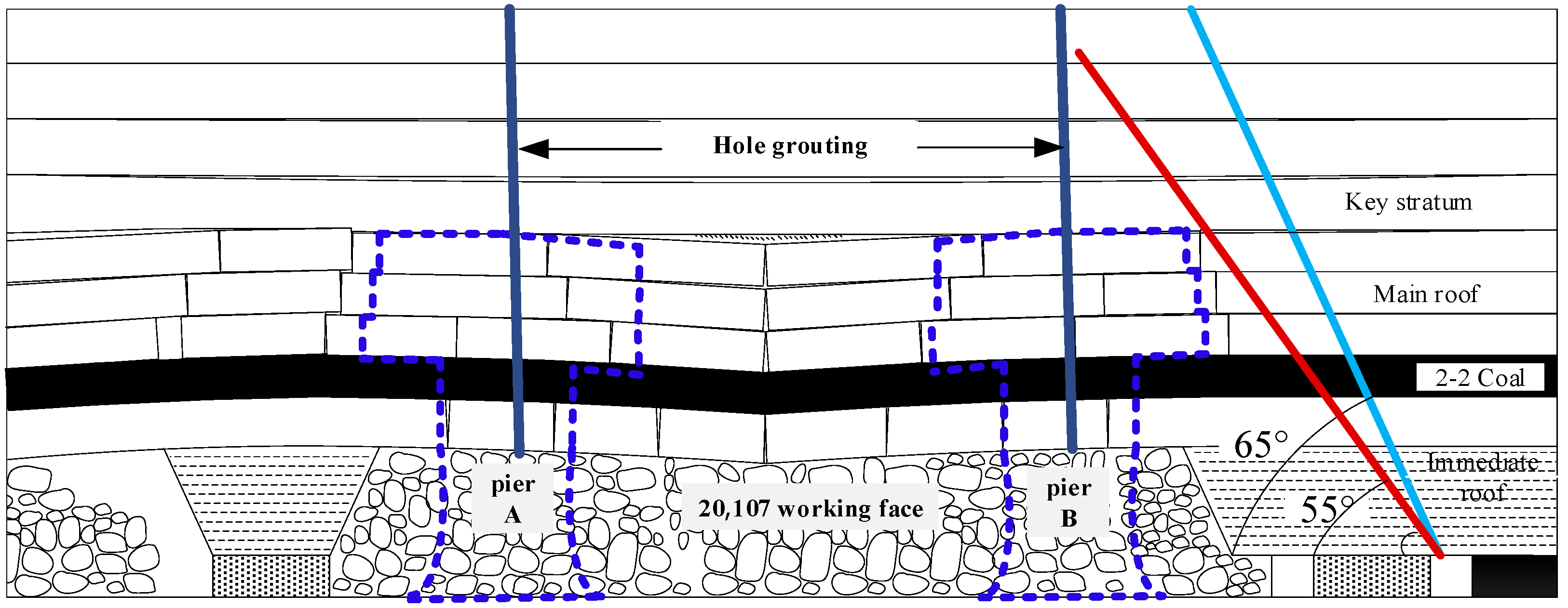
2. Principles of the Multi-Arch Pier-Column Technique

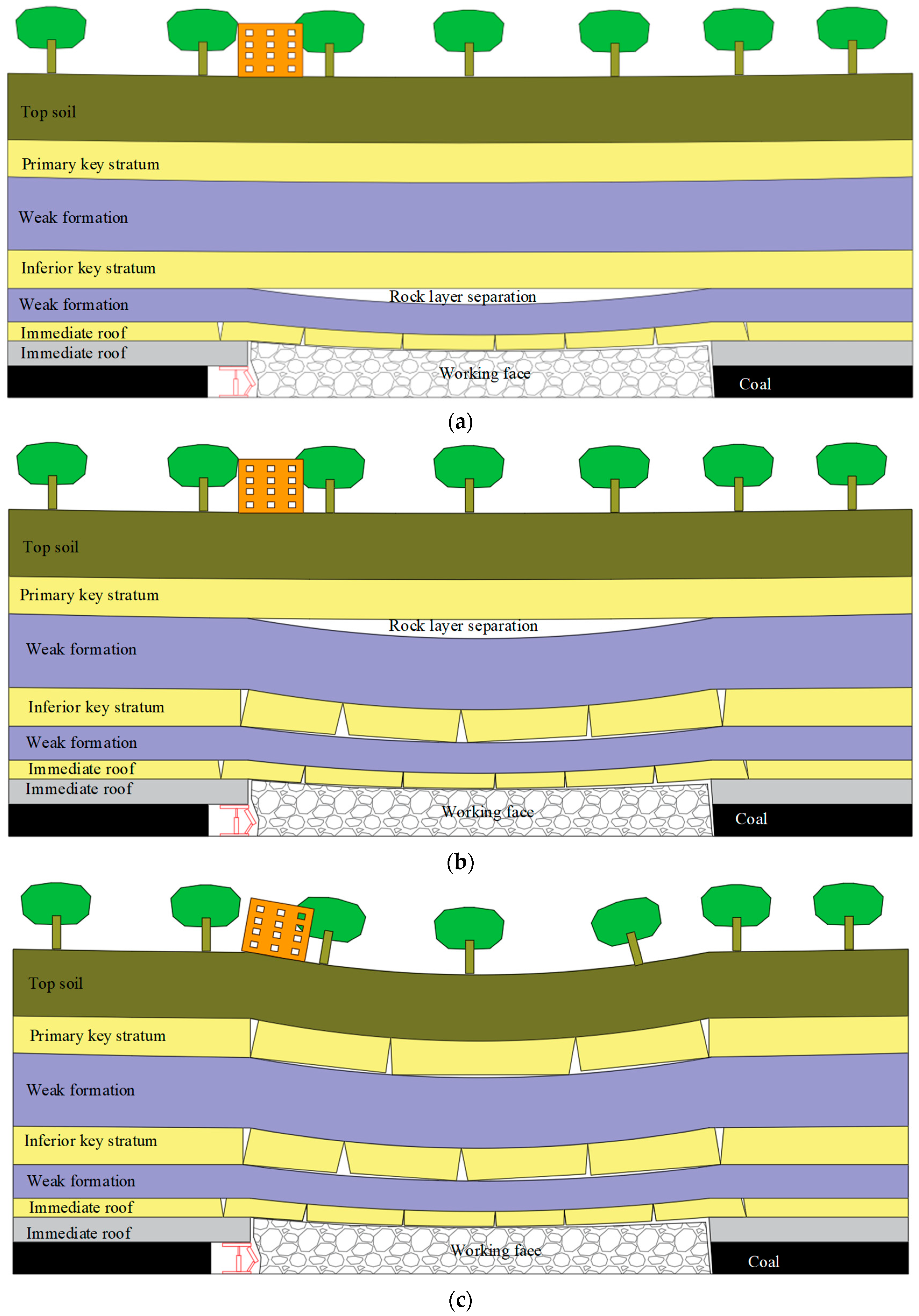
2.1. Role of Key Stratum

After the working face has been mined, the overlying rock layers are subject to movement and damage, such as collapse, fracture, fissure, separation, and bending, from the bottom to the top, and they continuously develop upwards, causing surface subsidence and building damage. The coal stratum is a typical stratified sedimentary rock layer with a variety of rock layers of different thicknesses and strengths depending on the time of rock formation and mineral composition, among which, one to several layers of thick, hard rock layers (both key stratums) play a controlling role in the movement of the rock layer. Studies have shown that this key stratum plays a controlling role in the dynamic process of surface movement, and the breakage of this stratum plays a controlling role in the dynamic process of the surface movement, leading to rapid subsidence of the surface [20,27,28,29]. Therefore, ensuring that the key stratum of the overburden does not break and destabilize is crucial to the design of surface subsidence control. Figure 1 shows a diagram of the roof development in the goaf.

2.2. Technical Process

The roof of the working face can be reduced to a “plate” structure for mechanical analysis and is consistent with the actual force characteristics. The mechanical calculation of the four-sided solid support plate can be calculated using the Galerkin method. According to the literature, as the working face advances, the breakage of the high key stratum is predominantly in the form of “horizontal O-X” breakage and “vertical O-X” breakage [13,30,31,32,33]. Owing to the characteristics of these two forms of breakage, after the working face is pushed and before the key stratum is broken, different forms of piers are used for slurry backfilling, so that the “separation area backfilling body + backfilling piers + key stratum + coal pillar” form a “multi-arch pier-column” stabilization structure. With this combination, the surface stability is maintained, and no residual subsidence occurs. Figure 2 shows the breakage form of the high key stratum.

2.2.1. Judgment of the Top Slab Overburden of Each Hard Rock Layer

Based on the methods of discriminating the key strata, such as those described by Xu and Qian [10,27,34,35,36], the location of the overlying key strata on the 20,107 working face of the Gaojialiang coal mine was determined. First, the overburden load of each hard rock layer was calculated. The layer 1 and layer m + 1 rock beams in the upper part of the coal seam were set as the hard rock layer.
E m + 1 h m + 1 2 i = 1 m h i V i > V m + 1 i = 1 m E i h i 3
where Ei is the modulus of elasticity of the i-th rock formation; hi is the thickness of the i-th rock formation, m; and Vi is the bulk weight of the i-th rock formation, m.
Starting from the first rock layer on the top of the coal seam, the parameters of each rock layer were substituted into Equation (1), and when the equation was satisfied, the m + 1 rock layer was marked as the first hard rock layer. The calculations were continued to determine the overlying rock layer of the first hard rock layer, until all hard rock layers were identified.

2.2.2. Calculation of Breakage Distance for Each Hard Rock Layer

After coal seam mining, the overlying strata continuously collapse from bottom to top. As the coal seam develops to the key strata, the key strata break periodically, resulting in the breakage of all or a part of the overlying strata, thus causing an extensive range of strata movement. The hard rock formation can be simplified by a solid support beam at both ends with a collapse step of:
l k = 2 h k e k q k = 2 h k e k j = 0 m k E k , j h k , j 3 E k , 0 h k , 0 3 j = 0 m k h k , j V k , j
where, lk is the breaking distance of the k-th layer rock beam, m; ek is the tensile strength of the k-th layer rock beam, MPa; and qk is the load applied to the k-th layer rock beam, MPa.
It is necessary to master the position and breaking step of the key strata, which has a guiding role for the partial filling mining method, based on the key strata theory.

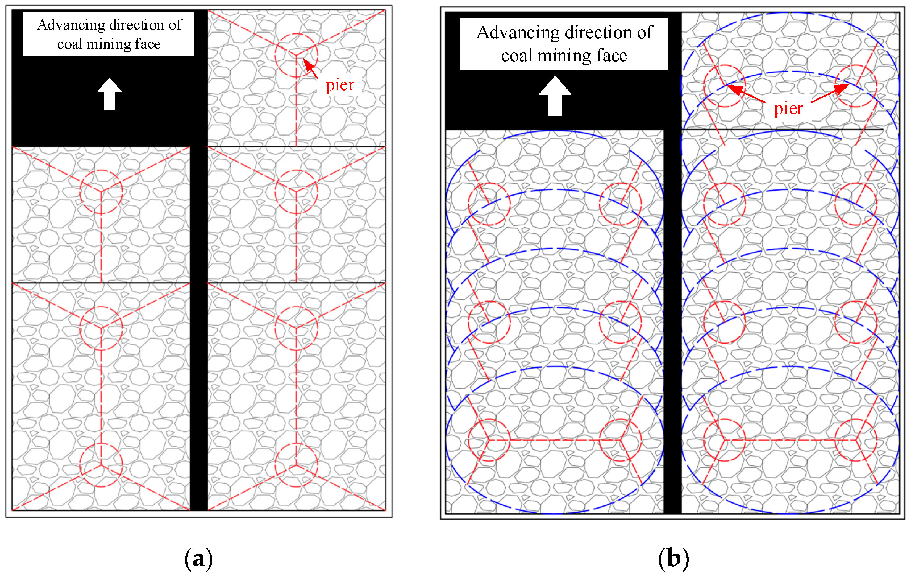
2.3. Technical Principles

When backfilling and managing the goaf, after the working face has been pushed through, the key stratum is identified before it is broken to fill the pre-fracture location. Holes are drilled in the surface to inject the backfilling injected slurry material into the goaf so that the broken gangue is cemented together and the separation layer is filled (with separation layer injected slurry), forming two or more types of “pier-column” structures. The structure is filled to the key stratum, and together with the key stratum, it forms a “multi-arch pier-column” stabilization structure to maintain the ground surface and prevent further subsidence. The backfilling location should be chosen at the pre-fracture line of the key stratum to prevent fracturing the key stratum and thus achieve the purpose of preventing surface subsidence.
The process of backfilling and supporting the key strata after the workings have been pushed can be divided into five stages.
In stage 1, as shown in Figure 1b, after the coal seam has been excavated, with the advance of the working face, the immediate roof first falls and fills the goaf, and the basic roof bends and sinks under the self-weight load, generating separation fissures between it and the key stratum.
In stage 2, as shown in Figure 1c, the roof break height in the goaf develops upwards, the key stratum bends and sinks to produce deflection, and when its ultimate sinking amount is reached, the overlying key stratum breaks, swivels, and sinks.
Stage 3, as shown in Figure 3a, is achieved by drilling holes in the surface of the goaf above the pre-fracture line of the key stratum before the key stratum reaches its ultimate settlement value.
In stage 4, as shown in Figure 3b, slurry backfilling is carried out by drilling holes in the goaf to strengthen the bearing capacity of the gangue.
In stage 5, as shown in Figure 3c, slurry is injected through the boreholes into the lower part of the key stratum in the separation area, to improve its stress state and ensure that the key stratum is not fractured.
The slurry backfilling material and the gangue in the goaf are glued together to form a “pier-column” structure, as shown in Figure 3c. The pier-column and the key stratum under the separation layer area between the filling body, together constitute a “multi-arch pier-column” backfilling support structure, which maintains the stability of the key stratum. This ensures that the key stratum does not break, and the surface subsidence value is within a safe range.
The control of surface subsidence is mainly reflected in two aspects. The first is the addition of backfilling materials, which cement and solidify the broken gangue in the goaf, forming two or more pier-column structures to improve the strength of the gangue in the goaf and reduce the subsidence of the roof. The second aspect is the backfilled pier-columns support the overburden rock to ensure that the key stratum is not subject to initial fracturing. This ensures the long-term stability of the key stratum and forms the “separation layer filling body + key stratum + backfilling pier-column + coal pillar” joint medium to maintain the surface layer and prevent new subsidence in the surface layer.

3. Evaluation of the Effectiveness of the Multi-Arch Pier-Column Strata Control

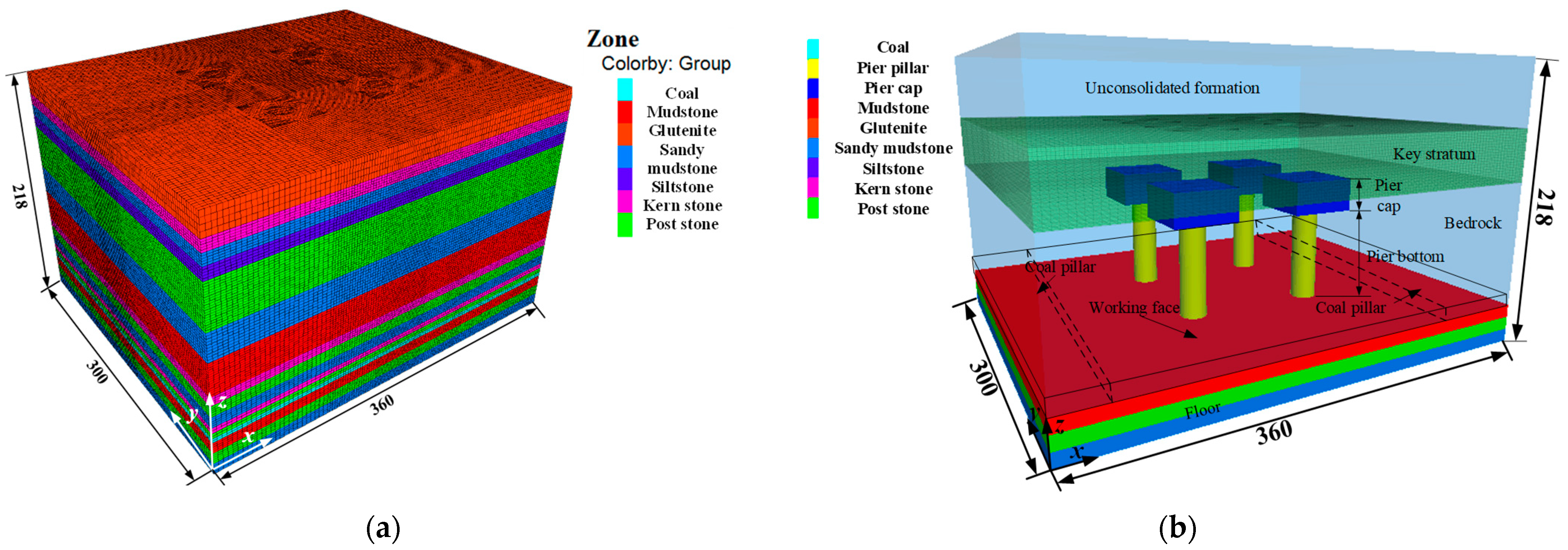
3.1. Research Methodology

The numerical simulation software FLAC3D was used to analyse the strata control effect of the multi-arch pier-column backfilling method and reveal the process of overburden movement and stress-displacement transfer in the shallow buried coal seam goaf. Taking the 20,107 working face of the Gaojialiang coal mine as the object of study, the physical and mechanical parameters of coal and rock are listed in Table 1.
The model adopted an ideal elastic-plastic model, leaving a certain boundary influence area on both sides of the working face and in the direction of advancement, and finally determined that the numerical model length × width × height = 360 m × 300 m × 218 m, respectively. Horizontal constraints were applied to the front, rear, left and right boundaries of the model, with the upper boundary free and the bottom boundary fixed. The compressive stress of 5 MPa was applied to the upper surface of the model to simulate the pressure of the overlying strata on the numerical model. On the contrary, the horizontal stress on the model was assigned based on the lateral pressure coefficient of 1.0. The range of the collapse zone rock mass (except for the pier-column) used a double-yield intrinsic model for filling, to realize the simulation of the collapse zone compaction and transference of the roof force.
In the numerical model, the piers shown in Figure 4 were established, and the key strata were backfilled for support. In the calculation, the parameters of the piers were set (considering that the piers were mainly formed by the slurry material cementing the gangue in the goaf, the parameters of the piers were set as the average value of the overburden rock parameters in the goaf), in order to simulate the overburden rock backfilling support in the goaf. The piers and the key strata together formed a multi-arch pier-column structure, which together maintained the stability of the surface of the goaf.

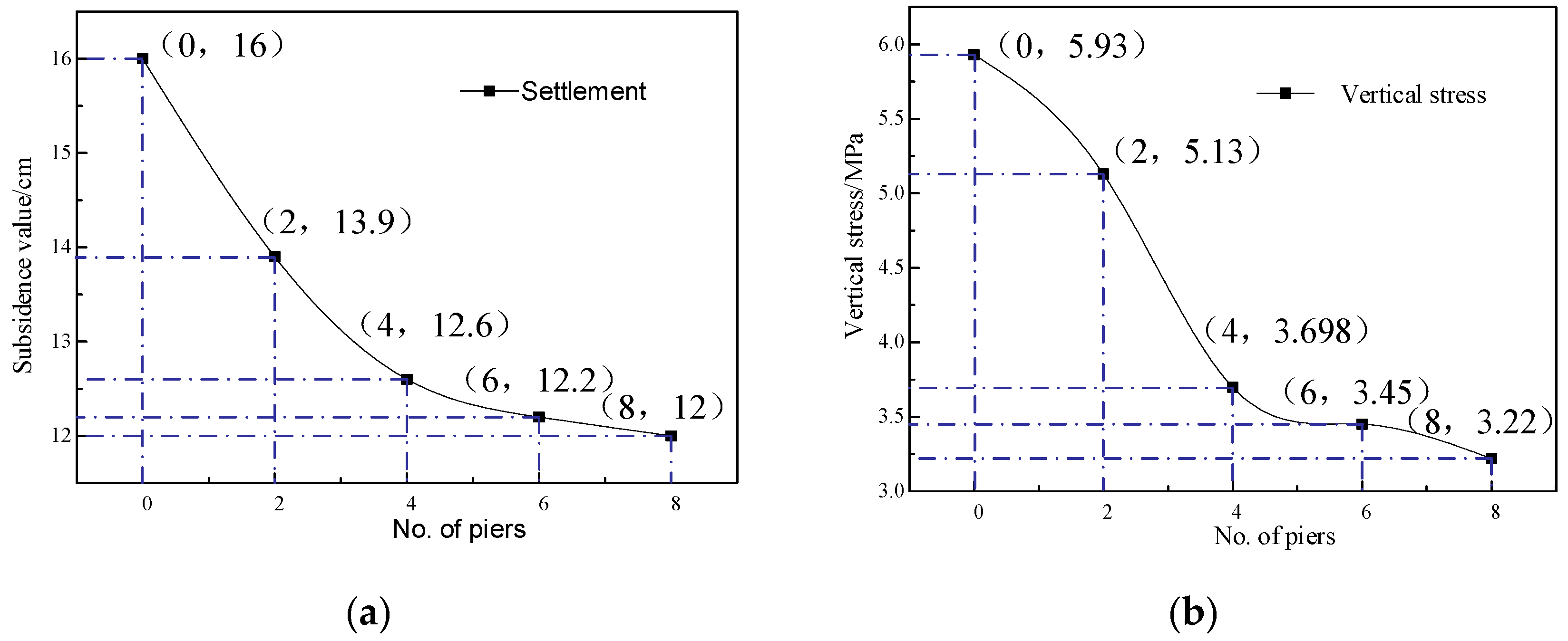
3.2. Results of Numerical Simulation

The model surface section (z = 218 m) was selected, and the displacement settlement of the model surface was recorded for different numbers of filled piers (density) after the working face was pushed, and the contour cloud of displacement settlement of this section was plotted, as shown in Figure 5.
When there was no backfilling in the legacy goaf, the vertical displacement of the model surface (z = 218 m) reached the maximum settlement of 16 cm in the middle and decreased in dispersion, and the influence range roughly presented a concentric ellipse shape. After the simulation of the number of filled piers, it was found that the maximum settlement was 14 cm, 12.5 cm, 12.3 cm, and 12 cm when two, four, six, and eight piers were filled and supported, respectively. With the increase in the number of filled piers, the surface subsidence value gradually decreased.
The changes in the distribution of vertical stresses in this cross-section with the excavation of the working face were analysed for the change in stress distribution caused by the number of filled piers on the support of the key stratum on the contact surface of the piers and the key strata, as shown in Figure 6.
After coal seam mining, when the remaining goaf is unfilled, the vertical stress of the overlying strata above the goaf is less; the minimum is 5.93 MPa, which expands from inside to outside, and the stress increases divergently. Stress concentration appears above the boundary coal pillar, and the vertical stress is 13.35 MPa. The simulation of the filling quantity of piers showed that when the number of piers in the remaining goaf was two, four, six, and eight, the minimum vertical stress of the roof was 5.93, 5.13, 3.69, 3.45, and 3.22 MPa, respectively. The vertical stresses above the coal pillar were 10.84, 9.40, 9.11, and 9.02 MPa, respectively. With the increase in the number of filling piers, the vertical stress above the goaf and coal pillar decreases significantly, which shows that filling piers can effectively improve the stress conditions of the overlying strata and coal pillars in the goaf.
After four piers were filled, with the increase in the number of filled piers, the maximum settlement value of the surface layer and the vertical stress on the roof and coal column in the goaf tended to decline and began to flatten, as shown in Figure 7. The analysis suggests that the backfilling improvement effect decreased because the filling tended to be saturated. All things considered, the best support state is when four pier-columns are filled.

4. Design of Goaf Filling Control Engineering

4.1. Drilling Process and Techniques

On-site drilling should be staked out using measuring instruments, such as a theodolite and level gauges, according to the design hole position (the vulnerable point of the key stratum), and the actual position of the borehole should not exceed 0.5 m from the designed position. The diameter of the borehole should be Φ150 mm. After drilling to 10 m below the key stratum, a Φ146 mm casing is run, and the entire section of the casing should be solidified using a single cement slurry with a quick-setting agent. The diameter should be changed to Φ118 mm to the final position of the borehole at the bottom of the working face (the hole slope should not exceed 1.5° per 100 m). This is filled to the key stratum, where the slurry and gangue solidify as one. Together they play a supporting role in the key stratum that helps to maintain the stability of the surface and prevent the occurrence of subsidence. The configuration of the single cement slurry is shown in Table 2.
The greater the water–cement ratio of the single-liquid cement slurry, the longer the setting time and viscosity of the slurry, and the smaller the stone rate and compressive strength. Based on the performance parameters of the slurry and the different formation types, the slurry with the corresponding water–cement ratio is selected to meet the requirements of field grouting. In the field grouting process, most grouts with a water–cement ratio (mass ratio) of 1:1 are selected, which can not only meet the strength of the grout stone body but also meet the requirements of grout injectability.
Compared to all other filling methods, the pier-type multi-arch filling method reduces the relocation cost of surface villages, and thus, the workload of the pier-type multi-arch filling method is reduced significantly. The practice has proved that the pier-type multi-arch filling method is a high-efficiency and low-cost filling coal mining technology, and its filling cost per ton of coal is only 40–80 yuan.

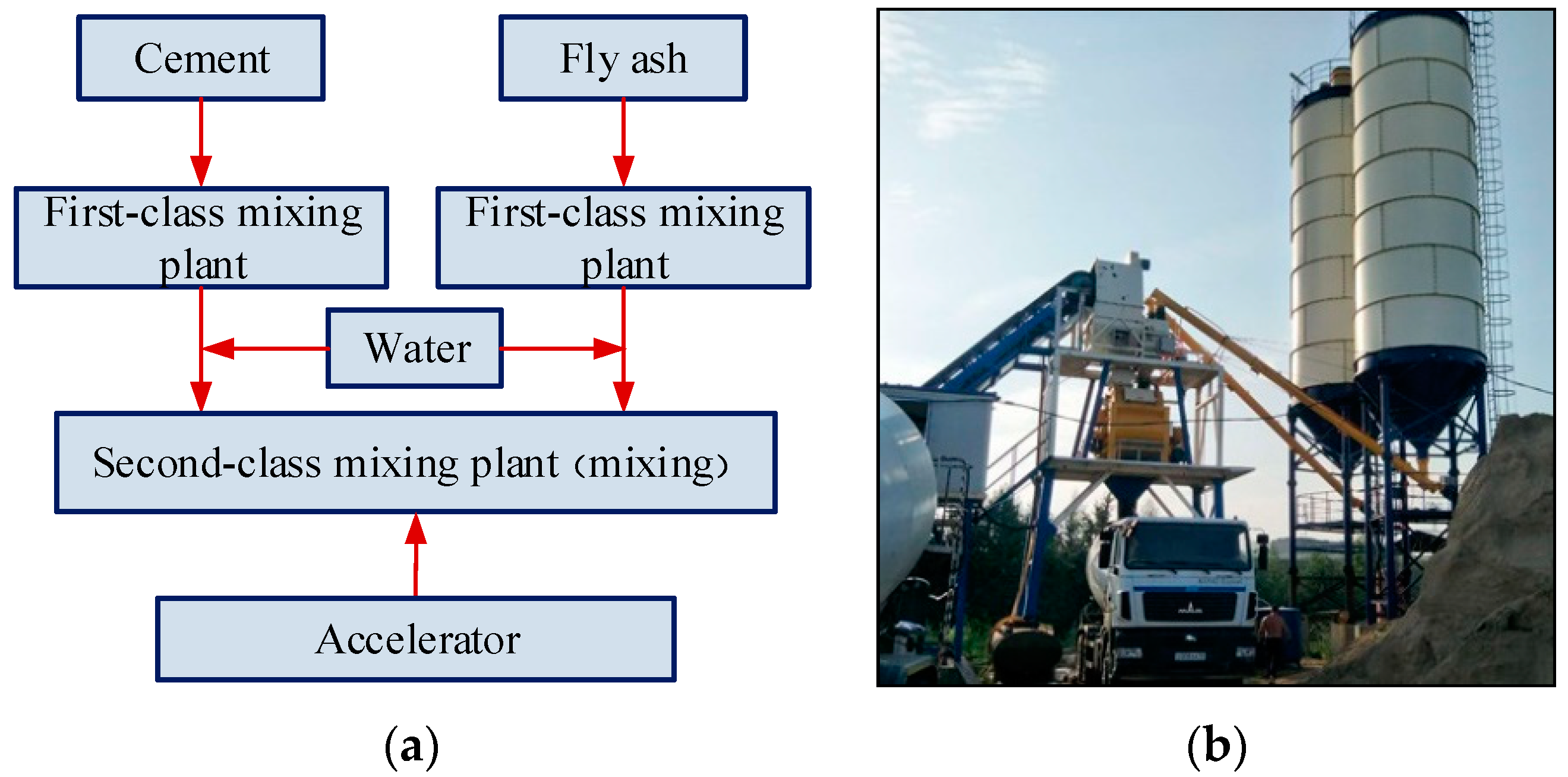
4.2. Injected Slurry Materials and Their Preparation

The injected slurry material consists of four ingredients: water, cement, fly ash, and coarse aggregate (sand). The cement is Po42.5 cement in accordance with the national GB175-2007 standard; the fly ash is national third-grade ash; the quick-setting agent is water glass, modulus 3.1–3.4, specification 40 Be. The cement–fly ash slurry with a water-solid ratio is 0.8:1–1:1. The fly ash to cement ratio is 3:1 [37,38,39]. If the amount of single-hole injected slurry is excessive, a quick-setting agent of 5–10% of the weight of the cement can be added to the slurry so that the slurry in the goaf solidifies quickly to prevent the loss of slurry. To ensure the backfill effectively limits the ground pressure and maintains the safety of the mining area, based on a thorough understanding of geological conditions, the strength requirements of the backfill comprise a uniaxial compressive strength of 2.5 MPa and a shear strength of 0.35 MPa.
After pouring cement and fly ash into the primary mixing plant separately, water is added to each and mixed separately. They should be mixed well and sent to the secondary mixing plant for mixing. The quick-setting agent should be added as appropriate, according to the onsite slurry leakage. A flow chart of the slurry making process and a photo of the mixing plant are shown in Figure 8.

5. Multi-Arch Pier-Column Infill Support and Results Analysis

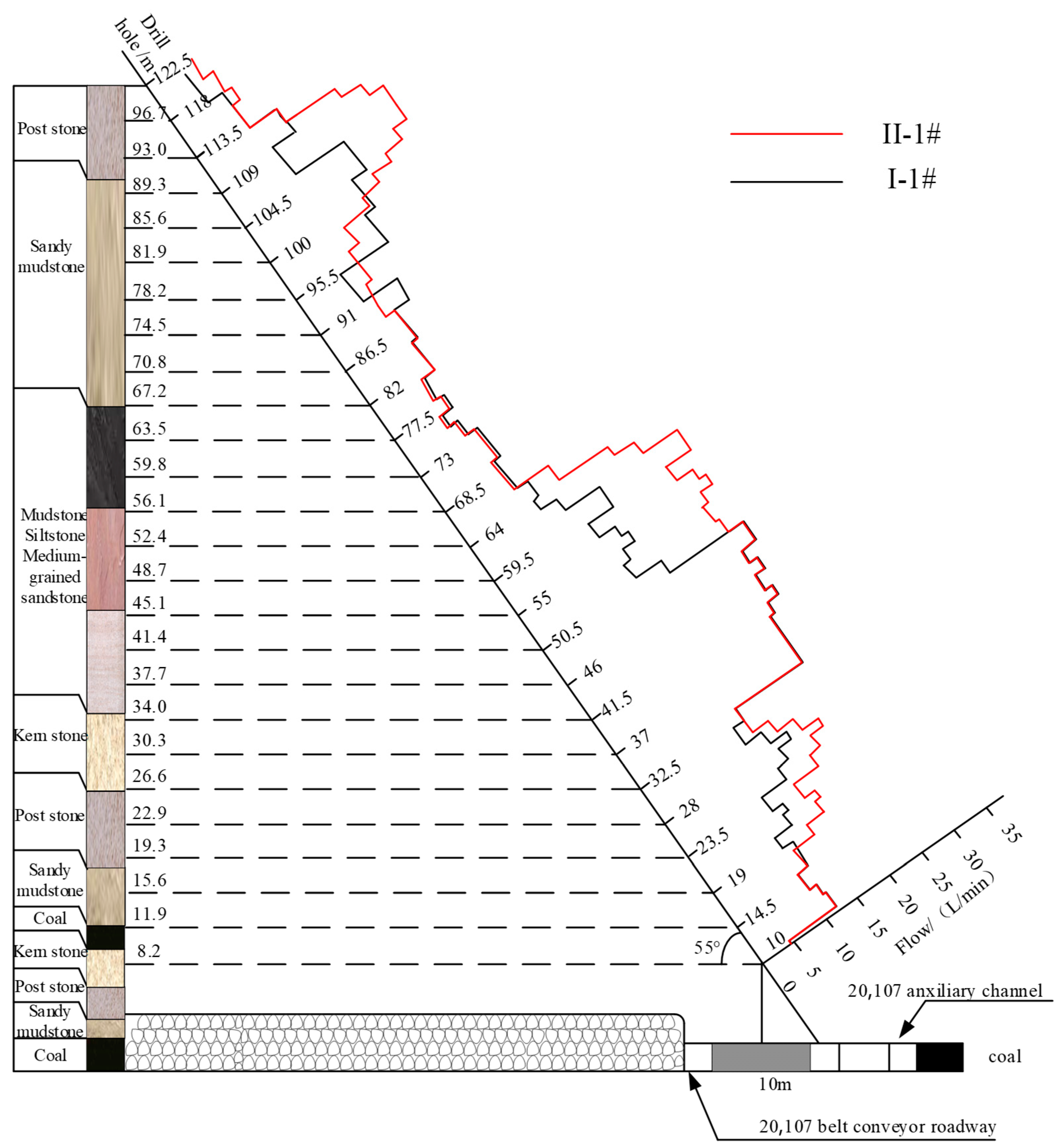
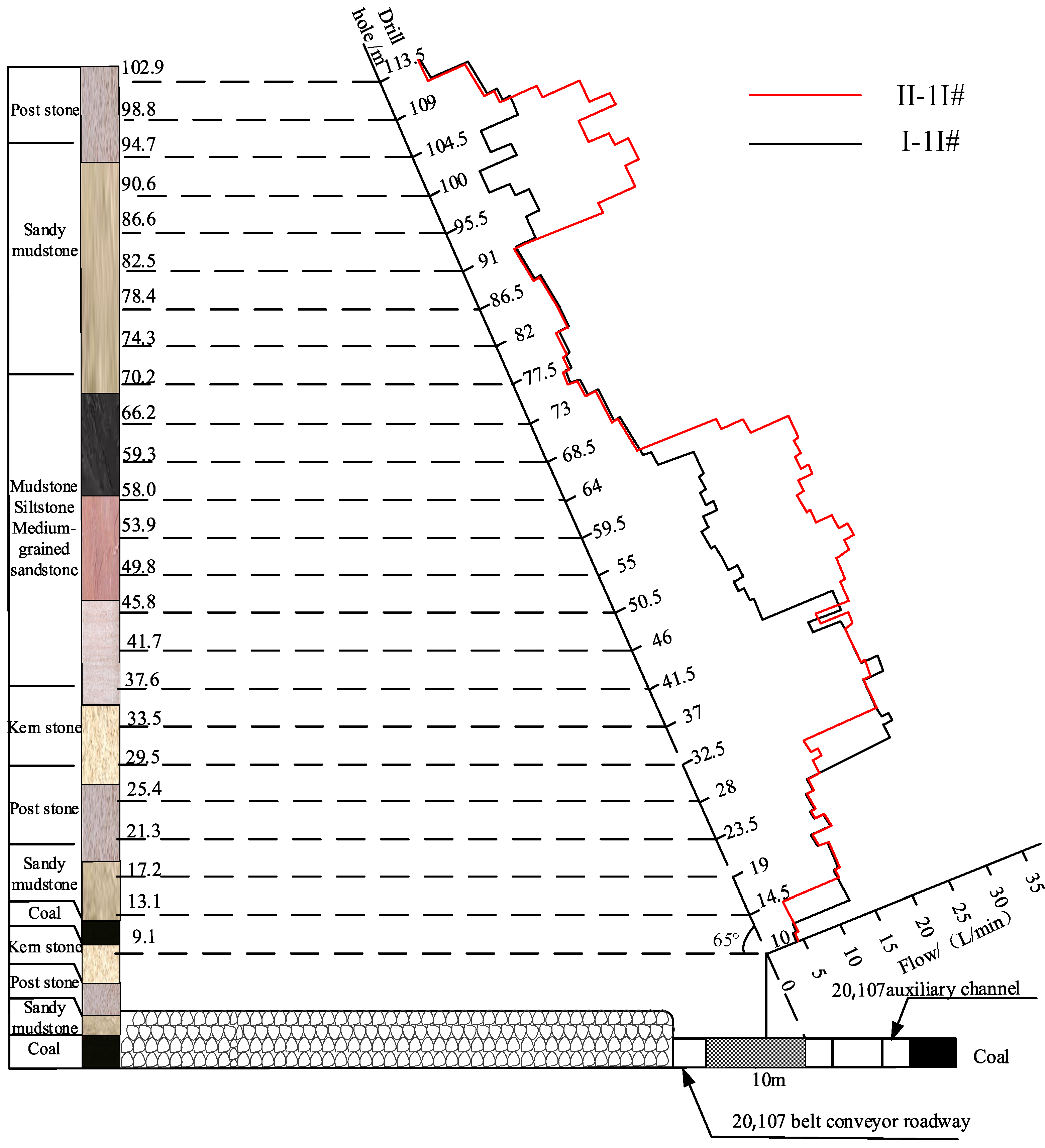
5.1. Shallow Stope Overburden Fracture Zone Detection

Detecting the development height and influence range of the overburden fracture zone after backfilling can not only reveal the overburden damage and transport of the shallow buried stope, but also reflect the filling effect. For the test group, we chose to set up the detection station in the filled working face, which contained two boreholes, namely I-1# and I-2#. For the control group, we chose to set up the detection station in the unfilled working face, which contained two boreholes, namely II-1# and II-2#. The overburden fracture zone of the stope was mainly detected using a double-end plugger device. Table 3 lists the borehole characteristics. The profile of the survey point arrangement is shown in Figure 9.
As shown in Figure 10, the leakage from the borehole is low in the drilling depth range of 0–15.6 m, indicating that the borehole has not yet entered the zone of separation or fracture areas. The leakage from the borehole increases in the drilling depth range of 15.6–56.1 m, indicating that this range is in the range of fracture zone development. The leakage after filling is significantly smaller than that without filling, and the volume of leakage after filling reduces first, indicating that the size and scope of separation after filling is reduced. In the drilling depth range of 56.1–78.2 m, there is less borehole leakage, indicating that the rock formation is in the bending and sinking zone, and the fissure has not developed. In the drilling depth range of 78.2–96.7 m, the leakage of the unfilled borehole suddenly increases, which is believed to be caused by separation between the key stratum and its underlying bedrock. The volume and extent of leakage after filling are smaller than that of the unfilled borehole, which indicates that the separation area between the key stratum and the underlying bedrock has been injected with slurry and is functioning, and the key stratum has been effectively controlled.
As illustrated in Figure 11, the leakage from the borehole is less in the drilling depth range of 0–13.1 m, which indicates that the borehole has not yet entered the separation or fracture areas. The leakage from the borehole increases in the drilling depth range of 13.1–59.3 m, which indicates that this is in the range of fracture zone development. The leakage after filling is significantly smaller than that without filling and the leakage after filling decreases first, which indicates that the size and extent of the separation layer after filling are both reduced. In the drilling depth range of 59.3–82.5 m, the leakage of the drill hole is less, which indicates that the rock is in the range of the bending and sinking zone, and the fracture has not developed. In the drilling depth range of 82.5–102.9 m, the leakage of the unfilled drill hole suddenly increases significantly, and the leakage of the filled drill hole increases a little, which indicates that the separation layer area between the key stratum and the bedrock below it has been injected with slurry and is functioning, and the key stratum has been effectively controlled.

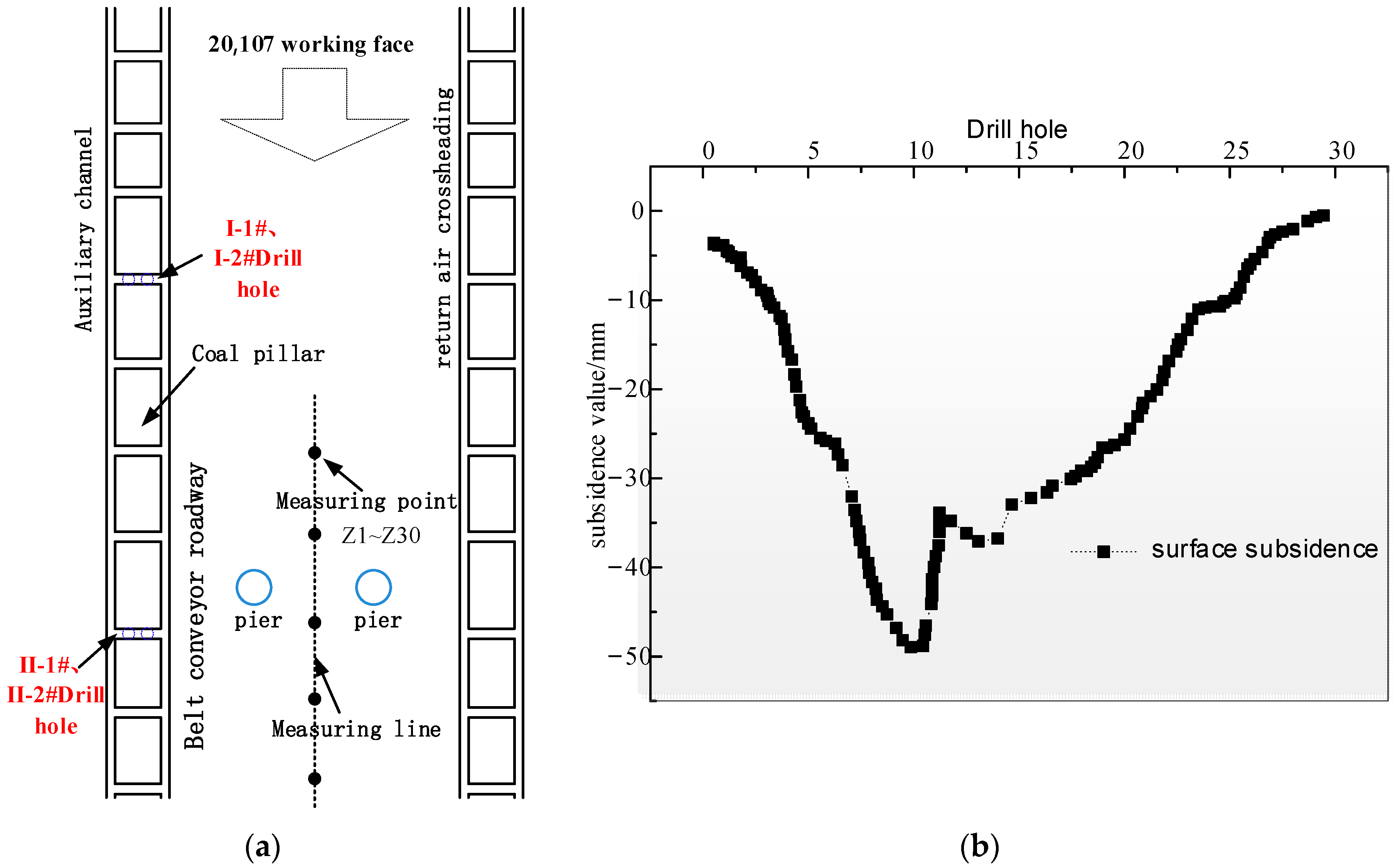
5.2. Surface Subsidence Detection

The measurement points were arranged at the surface along the direction of the working face, and numbered from Z1 to Z30, with two adjacent measurement points approximately 30 m apart on average, as shown in Figure 12a. Through field surface observations, the test filling area towards the surface subsidence was plotted and is shown in Figure 12b. When the goaf was filled, the maximum point dropped to approximately 50 mm, and the surface subsidence control effect was better.

6. Conclusions

(1) Based on the overlying rock key stratum on the surface subsidence control mechanism, we proposed a multi-arch pier-column filling method. The basic principle is to drill holes in specific locations on the surface and inject a slurry material into the goaf and the separation area between the key stratum and underlying rock layer, to cement the broken gangue in the goaf to form a stone body, improving its overall strength, and to fill the separation layer (the separation layer is injected with slurry) to form two or more types of pier structures, which together with the key stratum form a stable multi-arch pier-column structure. Controlling the key stratum and ensuring it does not break effectively reduces surface subsidence, ensuring that it remains in a safe range.
(2) In the multi-arch pier-column backfilling method, the filling body in the separation area is combined with the broken gangue in the goaf to form a stone body, and the remaining coal pillars share part of the overburden load on the key stratum and improve the stress state of the key stratum. In addition, the filling body in the separation layer can also limit the rotation and subsidence of the key stratum, ensuring that the key stratum does not break, and form a “separation area filler + filler pier-column + key stratum + coal pillar” joint medium to control the amount of surface subsidence.
(3) Numerical simulation analysis based on the nephogram of stress and displacement reveals that after coal seam mining, the stress of the overlying strata above the goaf decreases, and the stress concentrates above the boundary coal pillar. Thus, the pier-type multi-arch filling method effectively reduces the vertical stress above the goaf and the boundary coal pillar, implying that filling the pier-column improves the stress conditions of the overlying strata and the coal pillar in the goaf.
(4) Taking the Gaojialiang coal mine as a real-life example, through the detection of overburden rupture zones and surface subsidence monitoring it was found that the multi-arch pier-column backfilling structure effectively reduced the amount of separation and surface subsidence between the key stratum and its underlying rock layer. This indicates that the multi-arch pier-column filling technique can effectively control mining subsidence.

Author Contributions

Conceptualization, G.X.; project administration, K.F. and X.L.; supervision, X.S.; writing—original draft, G.X.; writing—review & editing, J.N., J.W. and G.S. and J.C. All authors have read and agreed to the published version of the manuscript.

Funding

This research received no external funding.

Informed Consent Statement

Written informed consent has been obtained from the patient(s) to publish this paper.

Acknowledgments

Thank you to the anonymous reviewers for their constructive and enlightened comments and suggestions in the revision process.

Conflicts of Interest

The authors declare no conflict of interest.

References

  1. Miao, X.X.; Qian, M.G. Research on Green Mining of Coal Resources in China:Current Status and Future Prospects. J. Min. Saf. Eng. 2009, 26, 1–14. [Google Scholar]
  2. Qian, M.; Jialin, X.U.; Wang, J. Further on the sustainable mining of coal. J. China Coal Soc. 2018, 43, 1–13. [Google Scholar]
  3. Qian, M.G.; Jia-Lin, X.U.; Miao, X.X. Green Technique in Coal Mining. J. China Univ. Min. Technol. 2003, 32, 344–348. [Google Scholar]
  4. Xu, J.L.; Xuan, D.Y.; Zhu, W.B.; Wang, X.Z.; Teng, H. Study and application of coal mining with partial backfilling. Meitan Xuebao/J. China Coal Soc. 2015, 40, 1303–1312. [Google Scholar]
  5. Huang, L.T. Research and development of mining subsidence mechanism. Coal Sci. Technol. 2003, 31, 54–56. [Google Scholar]
  6. Yan, W.T.; Guo, J.T.; Chen, J.J.; Tan, Y.; Yan, S.G.; Yan, Y.G. Severe Damage Law on the Ground Surface Induced by High-Strength Mining: A Case Study From the Shendong Coal Field in China. Front. Earth Sci. 2022, 10, 10. [Google Scholar] [CrossRef]
  7. Guo, G.; Wang, Y.; Ma, Z. A New Method for Ground Subsidence Control in Coal Mining. J. China Univ. Min. 2004, 33, 150–153. [Google Scholar]
  8. Sun, X. Present situation and prospect of green backfill mining in mines. Coal Sci. Technol. 2020, 48, 48–55. [Google Scholar]
  9. Zhu, X.J.; Zha, F.; Guo, G.L.; Zhang, P.F.; Cheng, H.; Liu, H.; Yang, X.Y. Subsidence Control Design Method and Application to Backfill-Strip Mining Technology. Adv. Civ. Eng. 2021, 2021, 5177174. [Google Scholar] [CrossRef]
  10. Al Heib, M.M.; Didier, C.; Masrouri, F. Improving Short- and Long-term Stability of Underground Gypsum Mine Using Partial and Total Backfill. Rock Mech. Rock Eng. 2010, 43, 447–461. [Google Scholar] [CrossRef]
  11. Li, S.; Zhao, Z.M.; Yu, H.X.; Wang, X.M. The Recent Progress China Has Made in the Backfill Mining Method, Part II: The Composition and Typical Examples of Backfill Systems. Minerals 2021, 11, 1362. [Google Scholar] [CrossRef]
  12. Zhu, W.B.; Xu, J.M.; Xu, J.L.; Chen, D.Y.; Shi, J.X. Pier-column backfill mining technology for controlling surface subsidence. Int. J. Rock Mech. Min. Sci. 2017, 96, 58–65. [Google Scholar] [CrossRef]
  13. Zhu, W.B.; Yu, S.C.; Xuan, D.Y.; Shan, Z.J.; Xu, J.L. Experimental study on excavating strip coal pillars using caving zone backfill technology. Arab. J. Geosci. 2018, 11, 14. [Google Scholar] [CrossRef]
  14. Ma, C.; Guo, X.Q.; Zhang, L.Y.; Lu, A.H.; Mao, X.B.; Li, B. Theoretical Analysis on Stress and Deformation of Overburden Key Stratum in Solid Filling Coal Mining Based on the Multilayer Winkler Foundation Beam Model. Geofluids 2021, 2021, 6693888. [Google Scholar] [CrossRef]
  15. Petlovanyi, M.; Mamaikin, O. Assessment of an expediency of binder material mechanical activation in cemented rockfill. J. Eng. Appl. Sci. 2019, 14, 3492–3503. [Google Scholar]
  16. Kostecki, T.; Spearing, A.J.S. Influence of backfill on coal pillar strength and floor bearing capacity in weak floor conditions in the Illinois Basin. Int. J. Rock Mech. Min. Sci. 2015, 76, 55–67. [Google Scholar] [CrossRef]
  17. Bai, J.; Cui, B.; Qi, T.; Zhu, W.; Kang, L. Fundamental theory for rock strata control of key pillar-side backfilling. Meitan Xuebao/J. China Coal Soc. 2021, 46, 424–438. [Google Scholar]
  18. Deng, K.; Zhang, D.; Zhang, Z. Study on Prediction and Control of Surface Subsidence in Deep Mining. J. China Univ. Min. 2000, 29, 52–55. [Google Scholar]
  19. Jia-Lin, X.U.; Qian, M.G.; Zhu, W.B. Study on influences of primary key stratum on surface dynamic subsidence. Chin. J. Rock Mech. Eng. 2005, 24, 787–791. [Google Scholar]
  20. Xu, J.; Zhu, W.; Li, X. Study of the technology of partial-filling to control coal mining subsidence. J. Min. Saf. Eng. 2006, 23, 6–11. [Google Scholar]
  21. Tang, W.; Sun, X.; Wang, H.; Shi, X.; Xiangyang, L.I.; Yi, L.I.; Mines, S.O. Study on effect of overlying strata stability during strip coal pillar excavation with paste backfilling. Coal Sci. Technol. 2017, 45, 109–115. [Google Scholar]
  22. Shahsavari, M.; Jafari, M.; Grabinsky, M.l. Influence of Load Path and Effective Stress on One-Dimensional Deformation of Cemented Paste Backfill (CPB) During Deposition and Curing. Geol. Eng. 2022, 40, 2319–2338. [Google Scholar] [CrossRef]
  23. Miao, X.; Ju, F.; Huang, Y.; Guo, G. New development and prospect ofbackfilling mining theory and technology. Zhongguo Kuangye Daxue Xuebao/J. China Univ. Min. Technol. 2015, 44, 391–399, 429. [Google Scholar]
  24. Bing-Nan, H. Backfill Mining Technology and Development Tendency in China Coal Mine. Coal Sci. Technol. 2012, 40, 1–5. [Google Scholar]
  25. Zhiqiang, W.; Xiaofei, G.; Yun, G.; Chaofan, C.; Pengfei, L.I.; Lei, W.; Jingli, Z. Study of grouting technology of overburden-separation to reduce ground subsidence in huafeng coal mine. Yanshilixue Yu Gongcheng Xuebao/Chin. J. Rock Mech. Eng. 2014, 33, 3249–3255. [Google Scholar]
  26. Li, X.S.; Xu, J.L.; Zhu, W.B.; Wang, X.Z. Theoretical study on the backfill grouting in caving area with strip mining. J. China Coal Soc. 2008, 33, 1205–1210. [Google Scholar]
  27. Xu, J.; Qian, M. Study on the influence of key strata movement on subsidence. J. China Coal Soc. 2000, 25, 122–126. [Google Scholar]
  28. Qin, W.; Xu, J.L. Discussion on Key stratum distinguishing method of overlying strata based on the thin slab theory. J. China Coal Soc. 2010, 35, 194–197. [Google Scholar]
  29. Yao, B.H.; Wang, D.K.; Wang, Y.G.; Wei, J.P. Mechanical mechanism study on the effect of fully-mechanized mining with filling on key strata deformation. Disaster Adv. 2013, 6, 196–203. [Google Scholar]
  30. Jiang, J.; Zhang, P.; Qin, G.; Fuchen, L.I.; Bin, X.U.; Lina, X.U. Fracture laws of one-side mined high-position hard thick key strata and microseismic energy distribution. J. Min. Saf. Eng. 2015, 32, 523–529. [Google Scholar]
  31. Jiang, J.Q.; Zhang, P.P.; Qin, G.P.; Xu, B. Analysis of destabilized fracture and microseismic activity of high-located main key strata. Yantu Lixue/Rock Soil Mech. 2015, 36, 3567–3576. [Google Scholar]
  32. Yu, B.; Zhu, W.; Li, Z.; Gao, R.; Liu, J. Mechanism of the instability of strata structure in far field for super-thick coal seam mining. Meitan Xuebao/J. China Coal Soc. 2018, 43, 2398–2407. [Google Scholar]
  33. Zhu, W.; Bin, Y.U. Breakage form and its effect on strata behavior of far field key stratum in large space stope. Coal Sci. Technol. 2018, 46, 99–104. [Google Scholar]
  34. Qian, M.; Miao, X.; Xu, J. Theoretical study of key stratum in ground control. J. China Coal Soc. 1996, 21, 225–230. [Google Scholar]
  35. Lin, X.J.; Qian, M.G. Method to Distinguish Key Strata in Overburden. J. China Univ. Min. Technol. 2000, 29, 463–467. [Google Scholar] [CrossRef]
  36. Lin, H.F.; Li, S.G.; Cheng, L.H.; Zhang, W. Key layer distinguishing method of overlying strata based on the thin slab theory. Meitan Xuebao/J. China Coal Soc. 2008, 33, 1081–1085. [Google Scholar]
  37. Behera, S.K.; Mishra, D.P.; Singh, P.; Mishra, K.; Mandal, S.K.; Ghosh, C.N.; Kumar, R.; Mandal, P.K. Utilization of mill tailings, fly ash and slag as mine paste backfill material: Review and future perspective. Constr. Build. Mater. 2021, 309, 125120. [Google Scholar] [CrossRef]
  38. Cavusoglu, I.; Yilmaz, E.; Yilmaz, A.O. Additivity effect on properties of cemented coal fly ash backfill containing water-reducing admixtures. Constr. Build. Mater. 2021, 267, 121021. [Google Scholar] [CrossRef]
  39. Pant, A.; Ramana, G.V.; Datta, M.; Gupta, S.K. Coal combustion residue as structural fill material for reinforced soil structures. J. Clean. Prod. 2019, 232, 417–426. [Google Scholar] [CrossRef]
Figure 1. Breaking Structure of Overburden Rock Migration in Stope Roof. (a) Immediate roof breakage; (b) Inferior key stratum breakage; (c) Primary key stratum breakage.
Energies 15 05845 g001
Figure 2. Breakage form of key stratum: (a) “Horizontal O-X” break; (b) “Vertical O-X” break.
Energies 15 05845 g002
Figure 3. Schematic diagram of multi-arch pier-column backfilling method. (a) Immediate roof breakage; (b) Backfilling of the void area; (c) Separation layer injected slurry and backfilling.
Energies 15 05845 g003
Figure 4. Numerical simulation of multi-arch pier-column backfilling and support model: (a) FLAC3D numerical simulation; (b) backfilling and support model.
Energies 15 05845 g004
Figure 5. Stress distribution map of backfilling support model for multi-arch pier-column numerical simulation: (a) No infill; (b) two pier-columns; (c) four pier-columns; (d) six pier-columns; (e) eight pier-columns.
Energies 15 05845 g005aEnergies 15 05845 g005b
Figure 6. Stress distribution map of backfilling support model for multi-arch pier-column numerical simulation: (a) No pier-columns; (b) two pier-columns; (c) four pier-columns; (d) six pier-columns; (e) eight pier-columns.
Energies 15 05845 g006aEnergies 15 05845 g006b
Figure 7. Stress/displacement variation curve of the numerical simulation backfilling support model of a multi-arch pier-column: (a) Displacement variation curve; (b) Stress variation curve.
Energies 15 05845 g007
Figure 8. Schematic diagram of the slurry-making process and the mixing plant: (a) Slurry-making process flow diagram; (b) Mixing plant.
Energies 15 05845 g008
Figure 9. Profile of survey point arrangement.
Energies 15 05845 g009
Figure 10. I-1# and II-1# Borehole Leakage Histogram.
Energies 15 05845 g010
Figure 11. I-2# and II-2# Borehole Leakage Histogram.
Energies 15 05845 g011
Figure 12. Surface Profile Subsidence Prediction Map: (a) Surface station layout plan; (b) Surface subsidence profile.
Energies 15 05845 g012
Table 1. Physical and mechanical parameters table of coal and rock seams.
RockinessHeight/mBulk Modulus/GPaShear Modulus/GPaInternal Friction Angle/°Internal Cohesion/MPaTensile Strength/MPaCompressive Strength/MPa
mudstone406.276.21262.803.7729
conglomerate (geology)2016.912.5312.206.444
sandstone mudstone556.506.32283.124.1523
siltstone1115.110.832.13.056.0042
coal43.581.45302.000.6518
coarse-grained sandstone2313.5611.3318.907.6040.15
fine-grained sandstone6511.808.20312.205.7028.78
backfill2.500.54351.300.752.5
Table 2. Single cement slurry formulation table.
Water to Ash Ratio W:CCement/bagWater/kgPulping Volume/m3Triple B/kgSalt/kgStone Rate/%Specific Gravity/(g/cm3)
0.6:1226601.00.5505.5981.76
0.75:1197121.00.4754.75971.62
1:1157501.00.3757.75851.49
Table 3. Borehole Characteristics.
Testing StationHole NumberHole Diameter mmAzimuthLocationAzimuthHole Depth m
Experimental groupI-1#89See borehole layout drawing 9Filling area55°122.5
I-2#8965°113.5
Control subjectsII-1#89See borehole layout drawing 9Unfilled areas55°122.5
II-2#8965°113.5
Publisher’s Note: MDPI stays neutral with regard to jurisdictional claims in published maps and institutional affiliations.

