
The Stress Evolution of Adjacent Working Faces Passing through an Abandoned Roadway and the Damage Depth of the Floor

Abstract
:1. Introduction
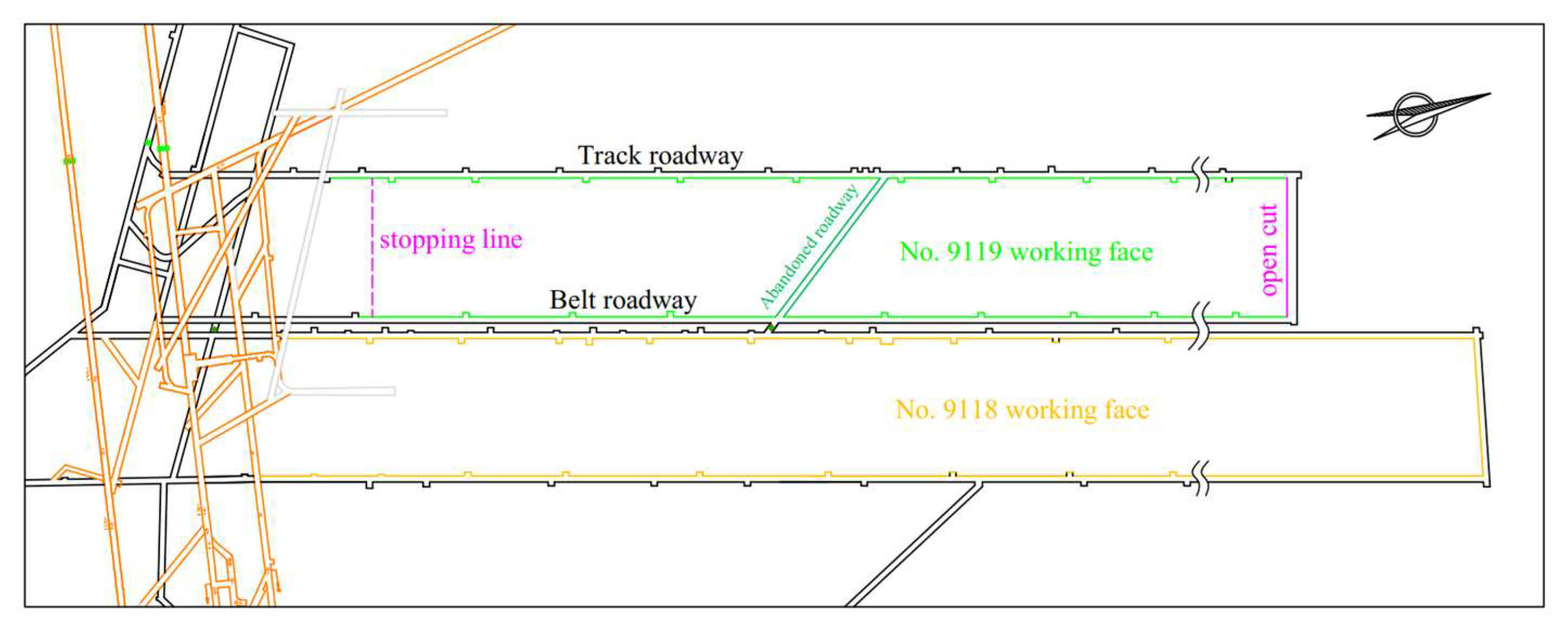
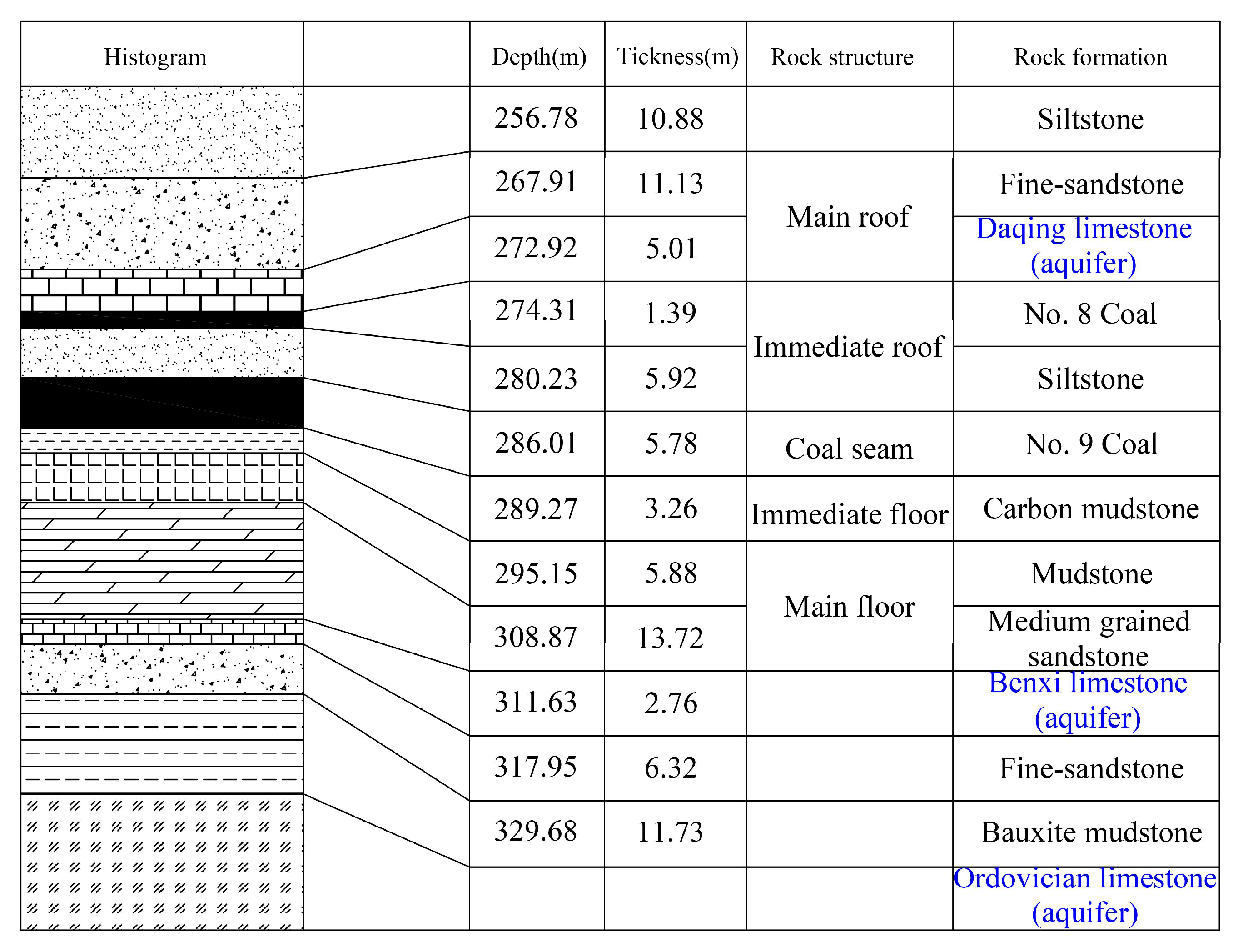
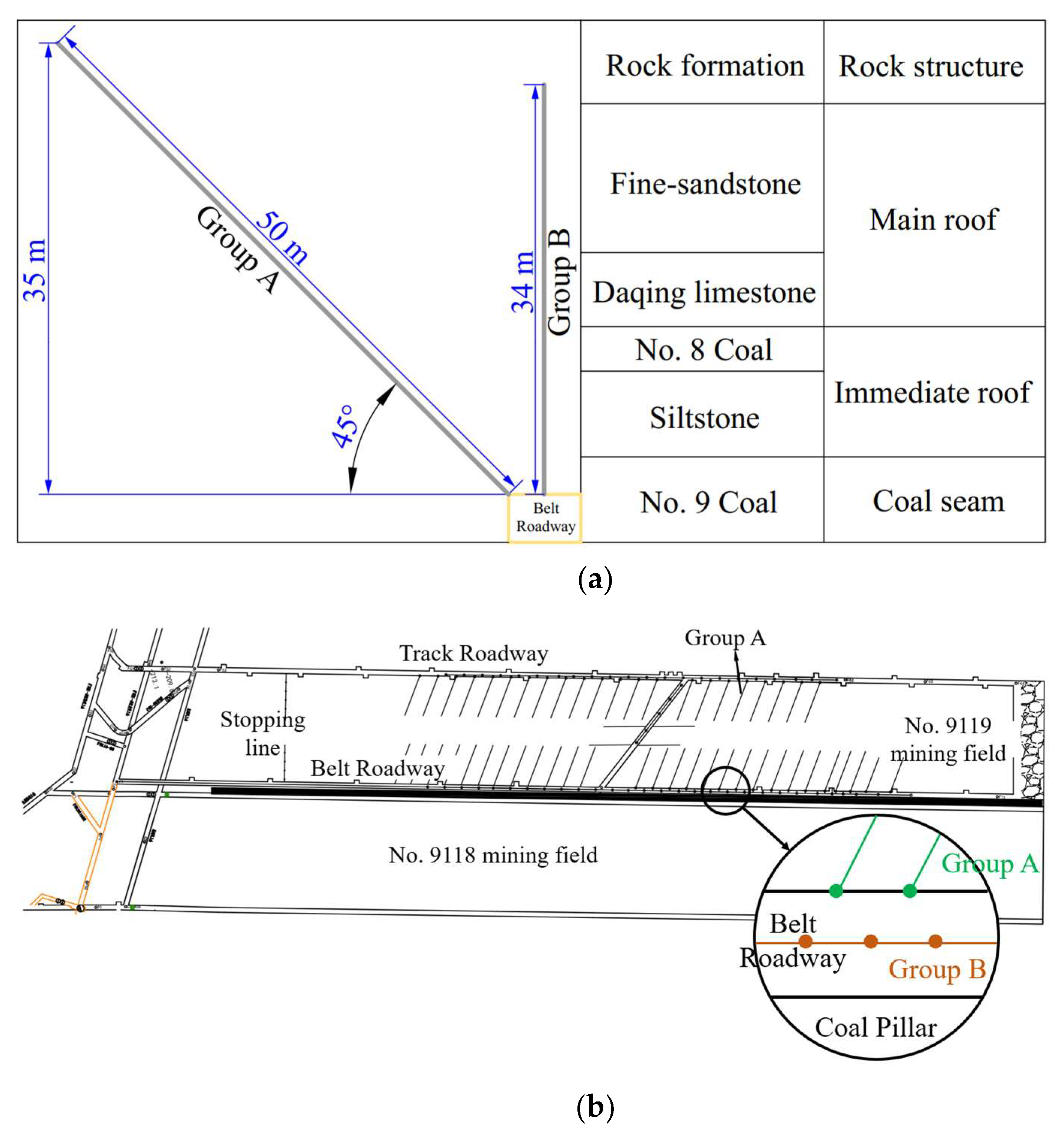
2. Project Overview
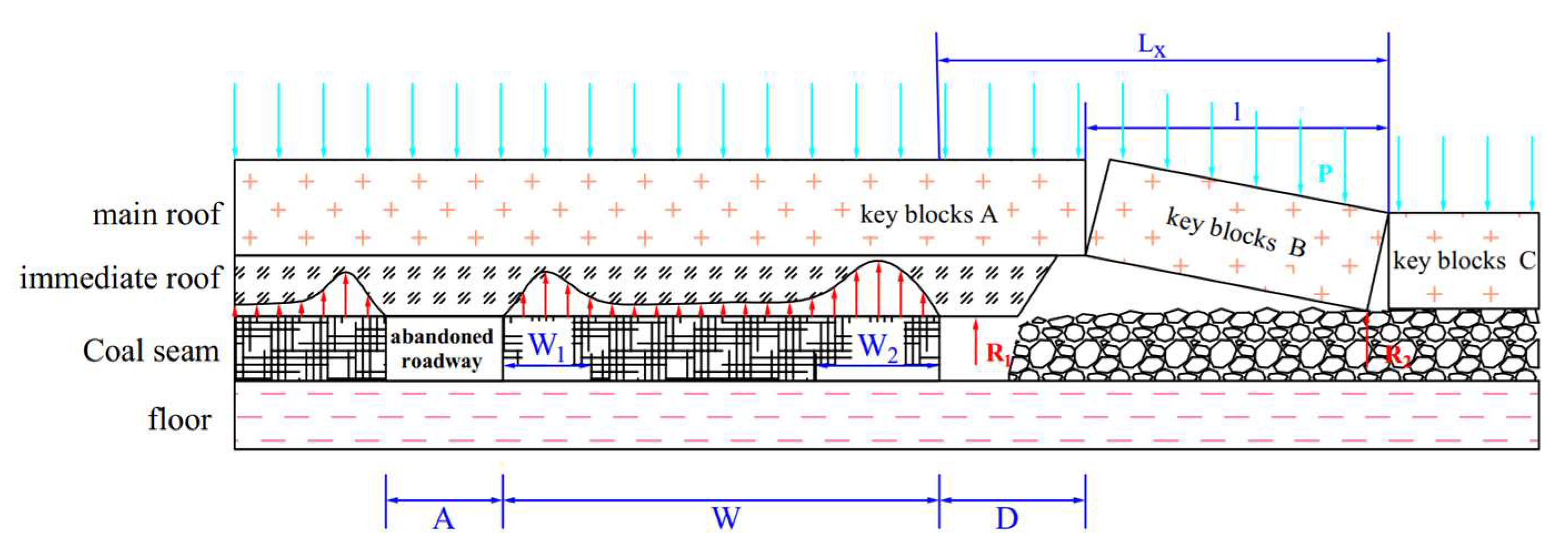
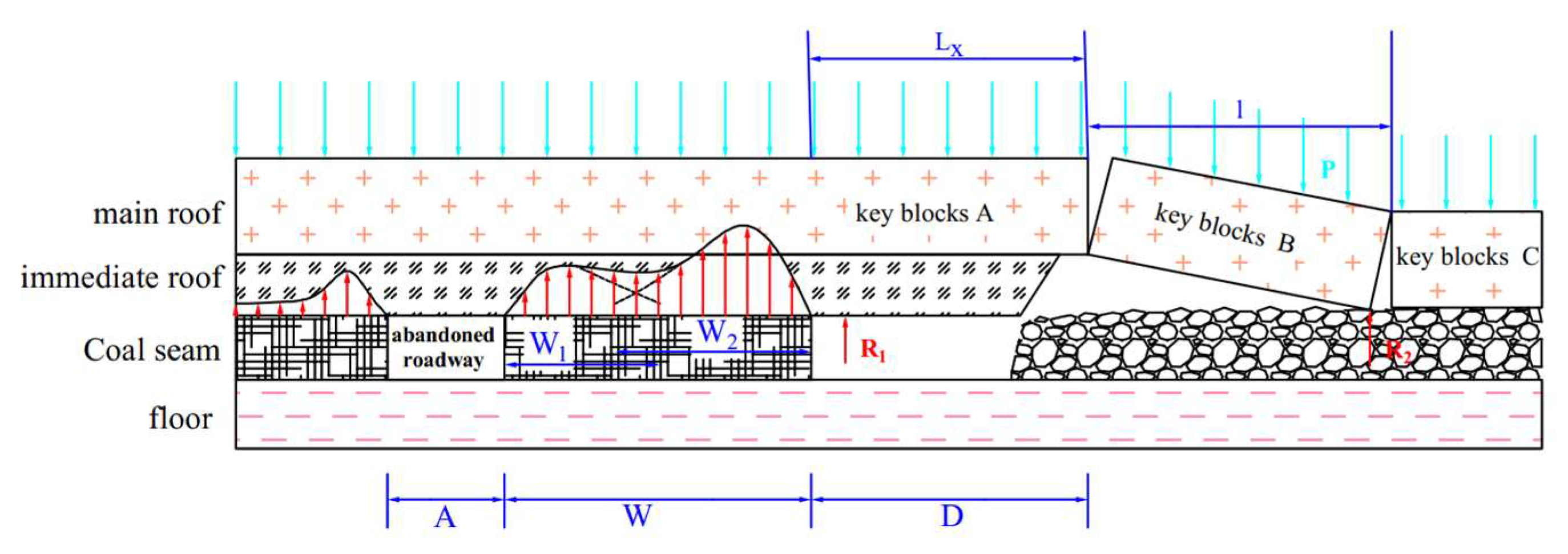
3. Stress Evolution of the Working Face Passing through an Abandoned Roadway
4. Numerical Simulation
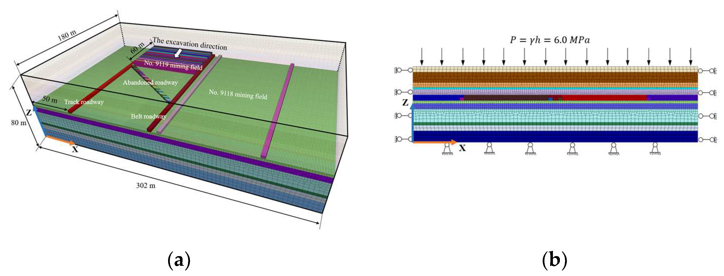
4.1. Three-Dimensional Numerical Model
4.2. Results
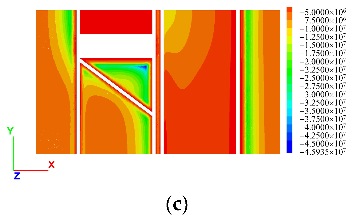
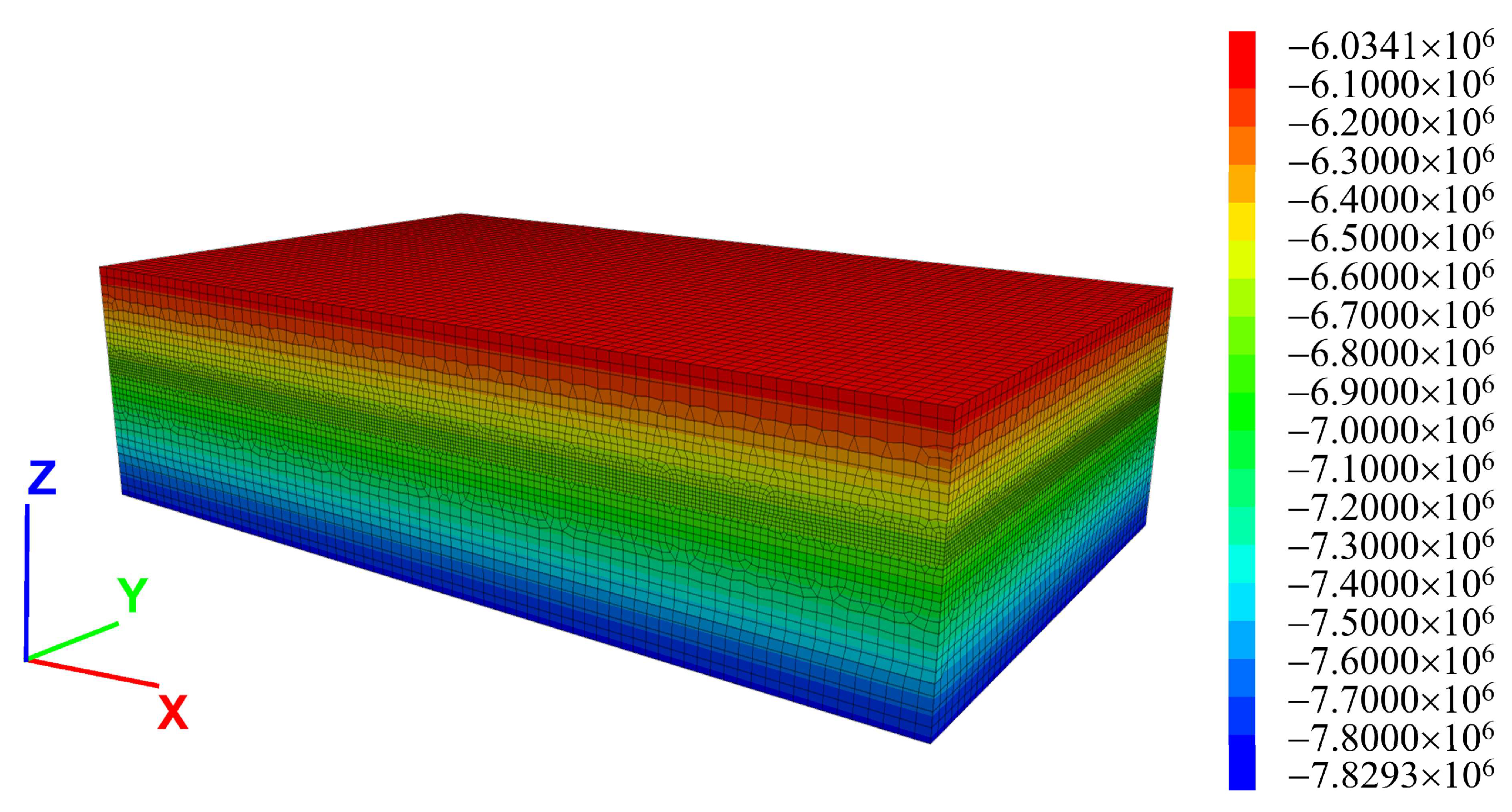
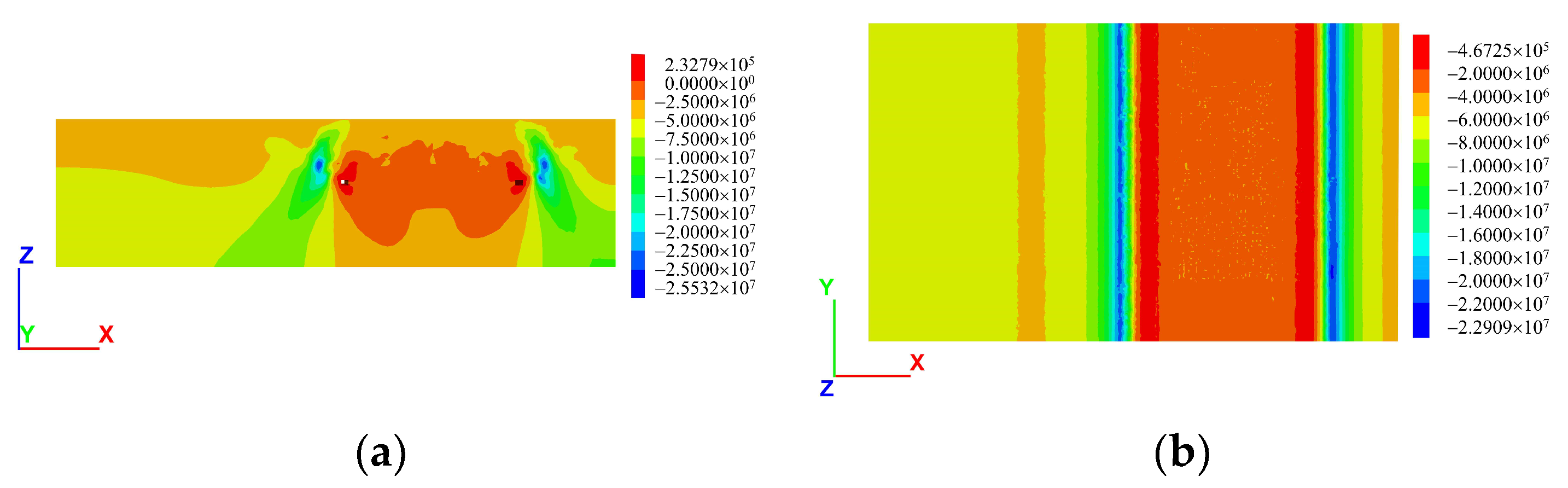
4.2.1. Initial Stress
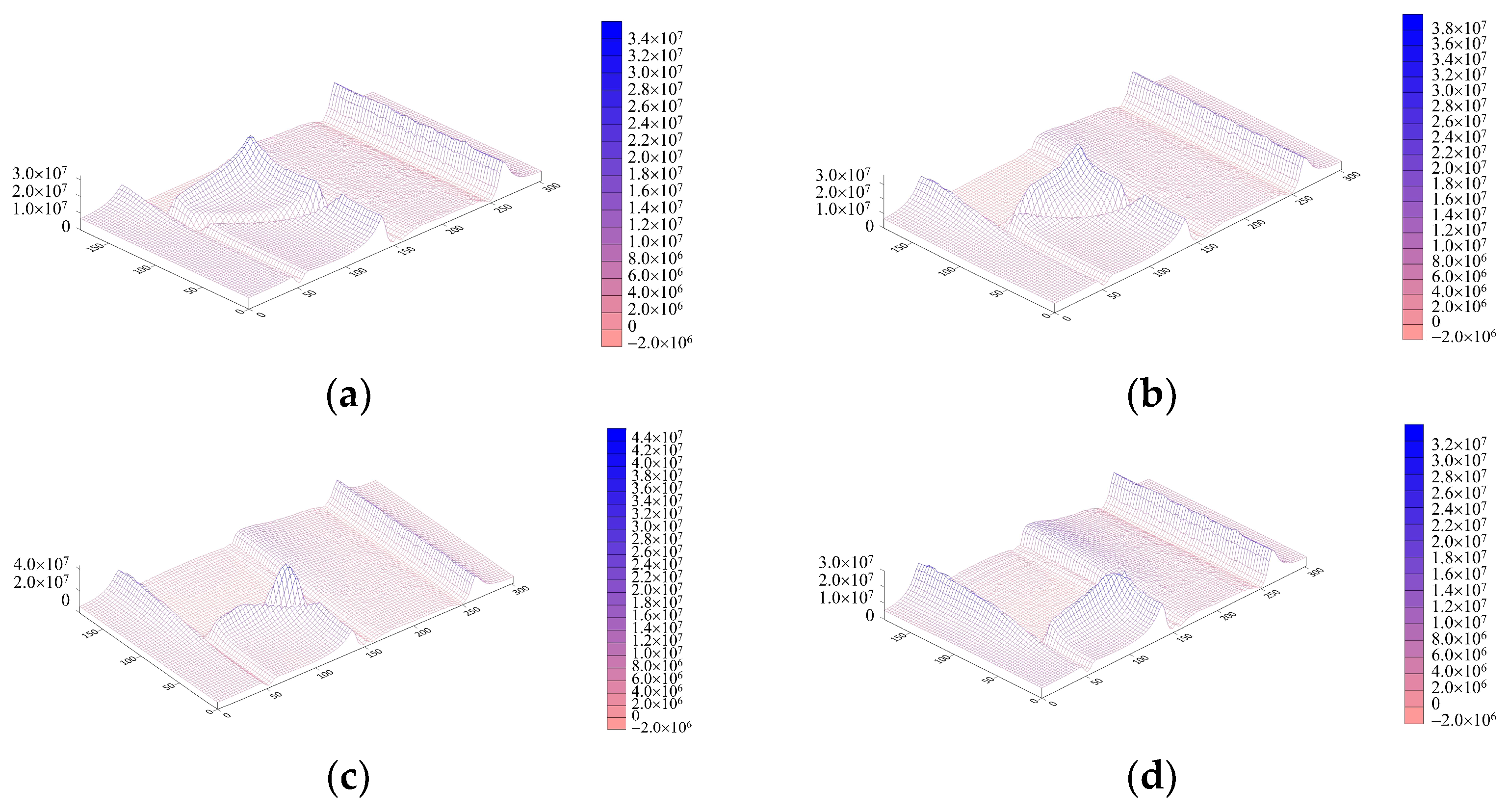
4.2.2. Stress Evolution of the Roof
- (1)
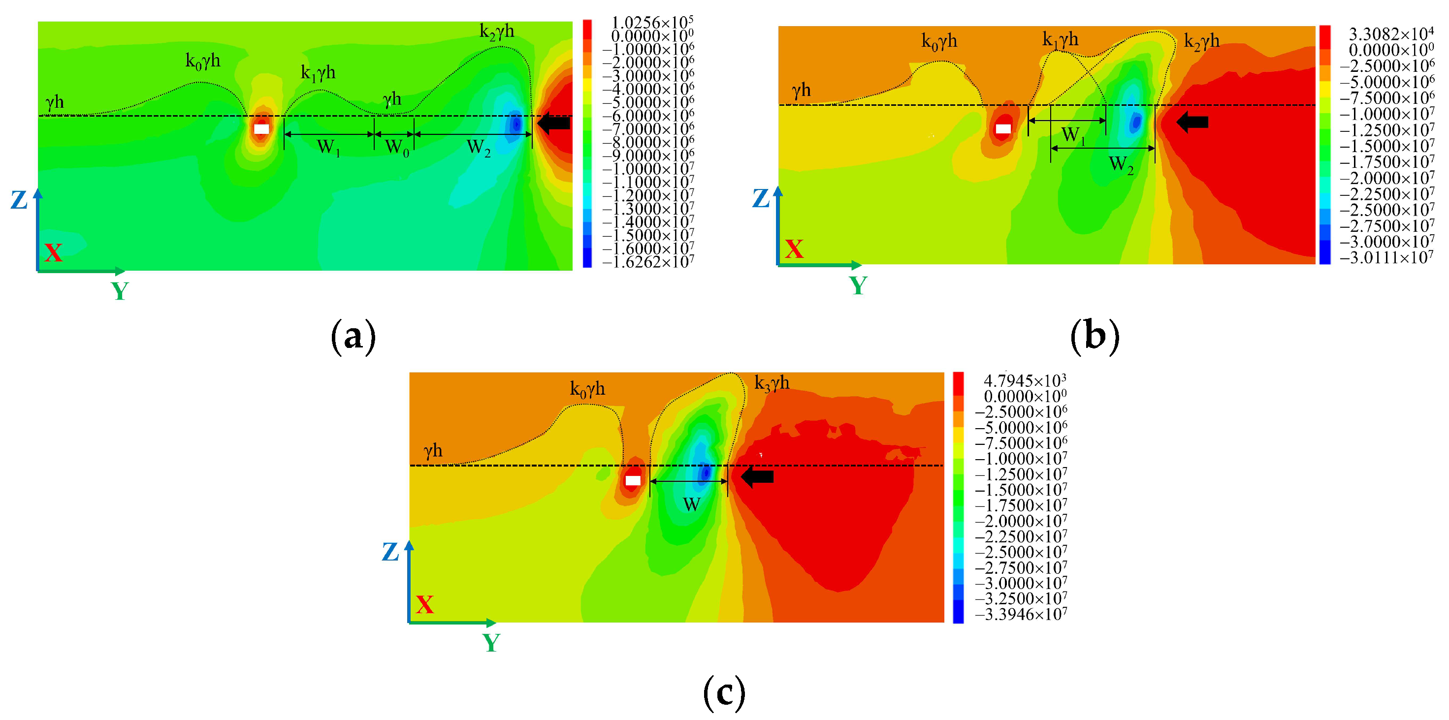
- As shown in Figure 11a, when the width of the coal pillar was 92 m in the middle of the working face and the abandoned roadway, the vertical stress of the coal pillar exhibited an asymmetric saddle type, with the peak stress (16.3 MPa) on the goaf-side being larger. The coal pillar midsection still contained the original rock stress zone, indicating that the front abutment stress was not affected by the abandoned roadway.
- (2)
- As shown in Figure 11b, when the width of the coal pillar was 52 m, the vertical stress of the coal pillar was an oblique table type, and the front abutment stress increased significantly, with peak stress of 30.1 MPa. The abutment stresses on both sides influenced one another.
- (3)
- As shown in Figure 11c, when the width of the coal pillar was 32 m, the vertical stress of the coal pillar was an asymmetrical peak type, with peak stress of 33.9 MPa. Currently, the abutment stress of the central coal pillar affects the abutment stress of the rear coal wall of the abandoned roadway, which results in a significant increase in the latter.
4.2.3. Effect of Weighting Steps on the Stability of the Roof and Floor
5. Results
5.1. Application of Hydraulic Fracturing Technology
5.2. Floor Grouting Reinforcement
5.3. Support for the Abandoned Roadway
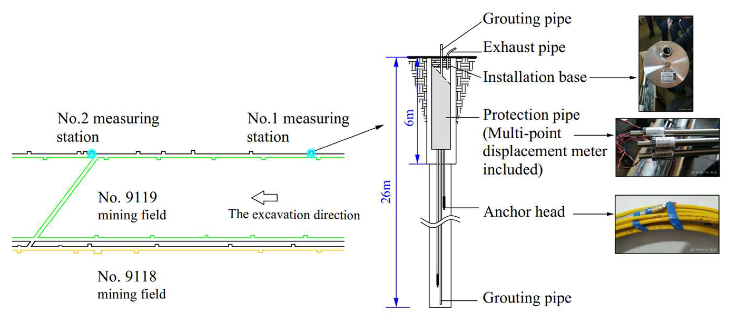
5.4. Verification Using the Field Monitoring
6. Conclusions
- (1)
- The stress evolution of the working face passing through the abandoned roadway can be characterised by the types of saddle, oblique table, and solitary peak. The critical width of the abandoned roadway where the main roof is bound to advanced break was calculated to be 5.4 m. With the width of the abandoned roadway determined, the suspended length of the main roof was the key factor in determining whether the main roof will advance break.
- (2)
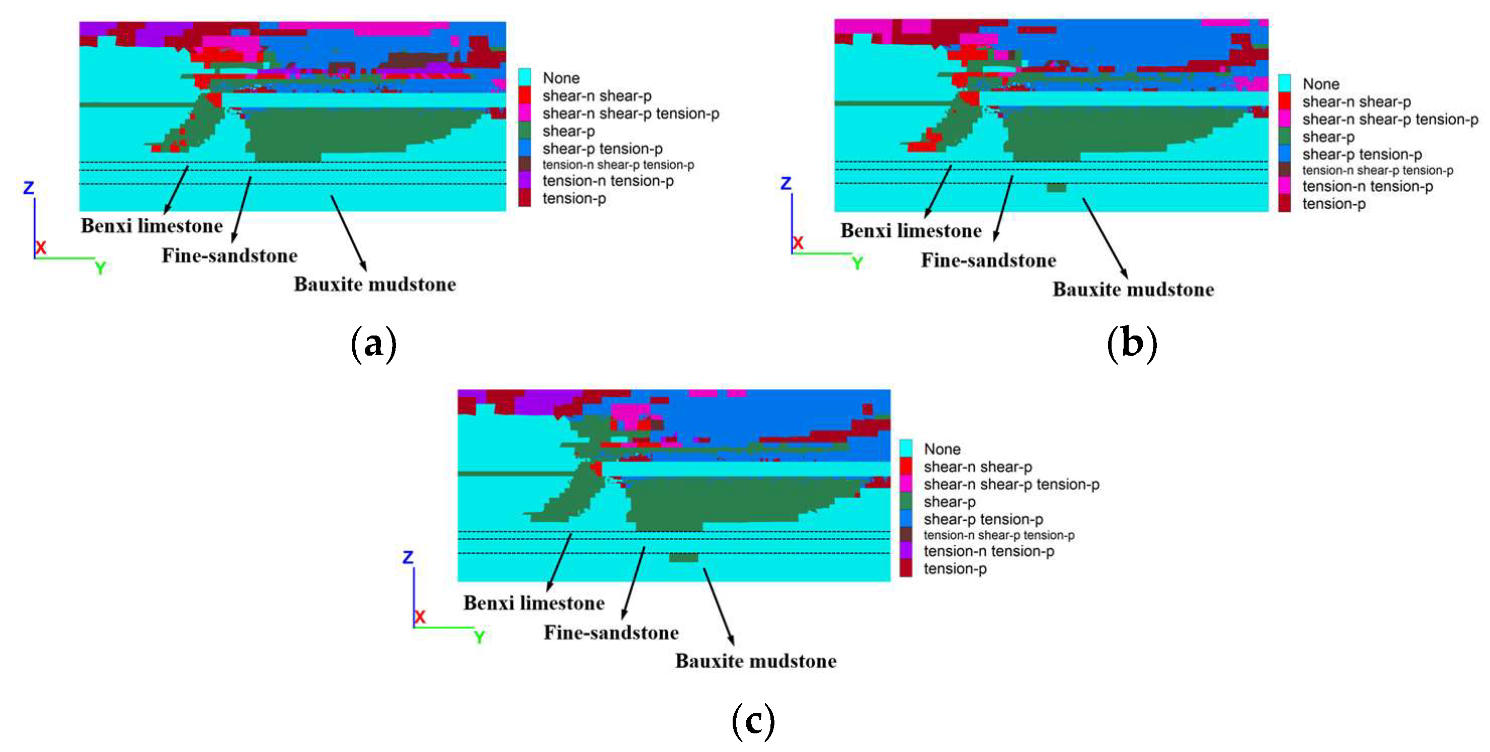
- Using elastomeric expressions to approximate fallen gravel, a Flac3D simulation method was proposed to simulate the stress evolution laws and the effect of different weighting steps. The error between the depths of the plastic zone obtained using this simulation method and the field monitoring data was within 15%.
- (3)
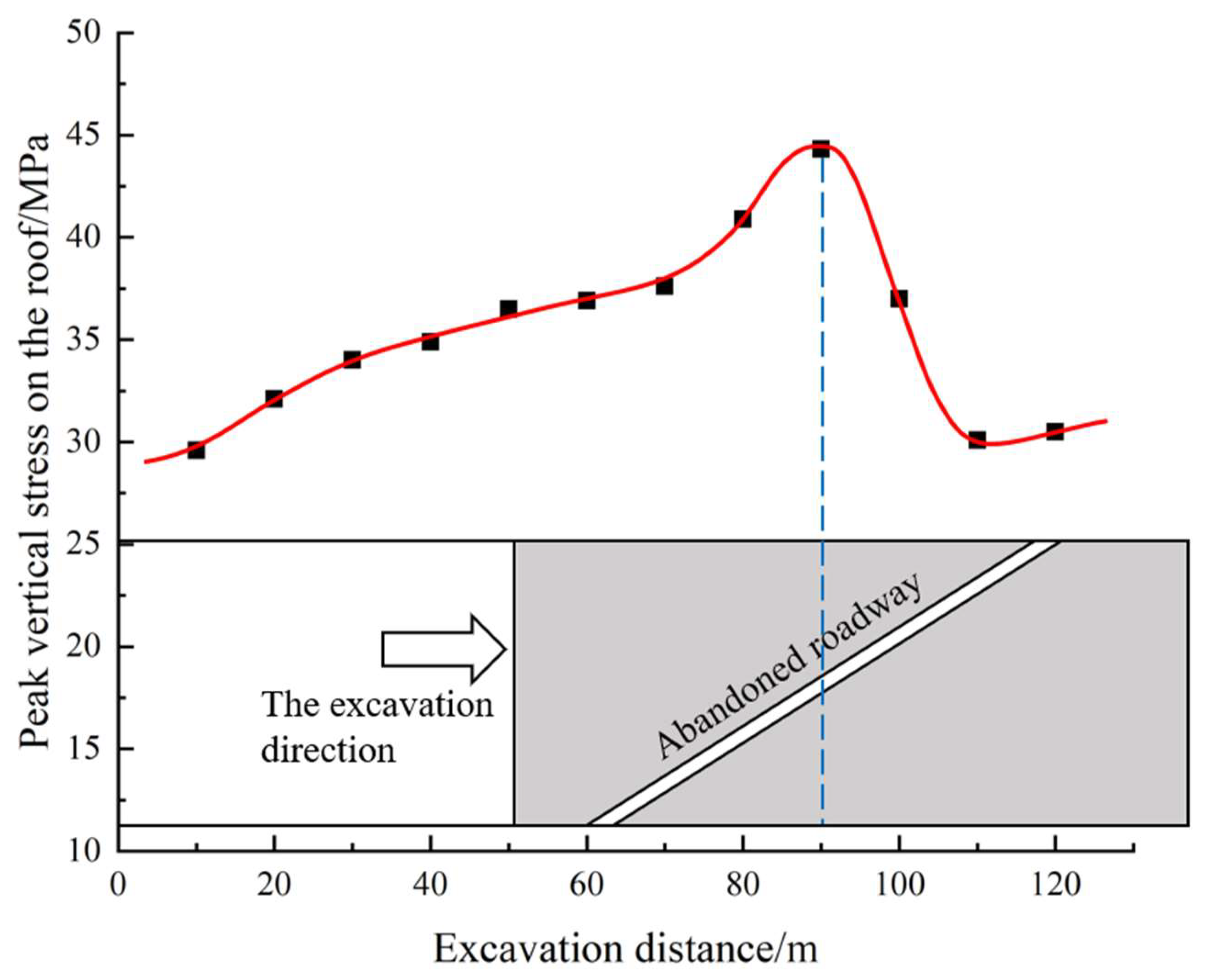
- The peak stress on the roof increased slowly when the working face was farther away from the abandoned roadway and then increased sharply when the working face began to expose the abandoned roadway. The maximum stress occurred at the working face through a semi-abandoned roadway, where the maximum stress reached 44.3 MPa. Subsequently, the area of the triangular coal pillar decreased, so the triangular coal pillar could no longer support the roof. The coal wall behind the abandoned roadway carried most of the front abutment stress, which caused the peak stress to slope downward.
- (4)
- The use of hydraulic fracturing technology to produce active roof release, with the aid of floor grouting reinforcement and support for abandoned roadways, was proposed as a holistic management technique. The damage depths of the floor strata from the field monitoring were 15 and 20 m, respectively, which showed that the measurements enabled the No. 9119 working face at Dongpang Mine to safely pass through the forward abandoned roadway and provided a significant reference for similar projects.
Author Contributions
Funding
Institutional Review Board Statement
Informed Consent Statement
Data Availability Statement
Acknowledgements
Conflicts of Interest
References
- Shi, L. Summary of Research on Mechanism of Water-inrush from Seam Floor. J. Shandong Univ. Sci. Technol. 2009, 28, 17–23. (In Chinese) [Google Scholar]
- Fan, J.; Liu, W.; Jiang, D.; Chen, J.; Tiedeu, W.N.; Chen, J.; Deaman, J.J.K. Thermodynamic and applicability analysis of a hybrid CAES system using abandoned coal mine in China. Energy 2018, 157, 31–44. [Google Scholar] [CrossRef]
- Liu, C.; Gong, P.; Wang, K.; Zhang, X.; Liu, Y. Roof stability for repeated mining workface passing through abandoned parallel gateway. J. China Coal Soc. 2015, 40, 314–322. (In Chinese) [Google Scholar]
- Liu, C.; Yang, Z.; Gong, P.; Wang, K.; Zhang, J.; Li, Y.; Zhang, X. Mechanism and control technology of supports crushing induced by main roof’s breaking ahead of workface when crossing abandoned roadway. J. China Coal Soc. 2017, 42, 1932–1940. [Google Scholar]
- Bai, Q.; Tu, S.; Zhang, C.; Zhu, D. Discrete element modeling of progressive failure in a wide coal roadway from water-rich roofs. Int. J. Coal Geol. 2016, 167, 215–229. [Google Scholar] [CrossRef]
- Chen, J.; Liu, P.; Liu, L.; Zeng, B.; Zhao, H.; Zhang, C.; Zhang, J. Anchorage performance of a modified cable anchor subjected to different joint opening conditions. Constr. Build. Mater. 2022, 336, 127558. [Google Scholar] [CrossRef]
- Chen, J.; Zeng, B.; Liu, L.; Tao, K.; Zhao, H.; Zhang, C.; Zhang, J.; Li, D. Investigating the anchorage performance of full-grouted anchor bolts with a modified numerical simulation method. Eng. Fail. Anal. 2022, 141, 106640. [Google Scholar] [CrossRef]
- Bai, J.; Shen, W.; Guo, G.; Wang, X.; Yu, Y. Roof Deformation, Failure Characteristics, and Preventive Techniques of Gob-Side Entry Driving Heading Adjacent to the Advancing Working Face. Rock Mech. Rock Eng. 2015, 48, 2447–2458. [Google Scholar] [CrossRef]
- Coggan, J.; Gao, F.; Stead, D.; Elmo, D. Numerical modelling of the effects of weak immediate roof lithology on coal mine roadway stability. Int. J. Coal Geol. 2012, 90–91, 100–109. [Google Scholar] [CrossRef]
- Cheng, Y.M.; Wang, J.A.; Xie, G.X.; Wei, W.B. Three-dimensional analysis of coal barrier pillars in tailgate area adjacent to the fully mechanized top caving mining face. Int. J. Rock Mech. Min. Sci. 2010, 47, 1372–1383. [Google Scholar] [CrossRef]
- Jiang, L.; Zhang, P.; Chen, L.; Hao, Z.; Sainoki, A.; Mitri, H.S.; Wang, Q. Numerical Approach for Goaf-Side Entry Layout and Yield Pillar Design in Fractured Ground Conditions. Rock Mech. Rock Eng. 2017, 50, 3049–3071. [Google Scholar] [CrossRef]
- Yu, H.; Niu, Z.; Kong, L.; Hao, C.; Cao, P. Mechanism and technology study of collaborative support with long and short bolts in large-deformation roadways. Int. J. Min. Sci. Technol. 2015, 25, 587–593. [Google Scholar] [CrossRef]
- Yuan, X.; Yang, S.S. Interaction principle of rock-bolt structure and Rib control in large deformation roadways. Arch. Min. Sci. 2021, 66, 227–248. [Google Scholar]
- Jing, L. A review of techniques, advances and outstanding issues in numerical modelling for rock mechanics and rock engineering. Int. J. Rock Mech. Min. Sci. 2003, 40, 283–353. [Google Scholar] [CrossRef]
- Ma, S.; Nemcik, J.; Aziz, N. Simulation of fully grouted rockbolts in underground roadways using FLAC2D. Can. Geotech. J. 2014, 51, 911–920. [Google Scholar] [CrossRef]
- Liu, X.; Tan, Y.; Ning, J.; Tian, C.; Wang, J. The height of water-conducting fractured zones in longwall mining of shallow coal seams. Geotech. Geol. Eng. 2015, 33, 693–700. [Google Scholar] [CrossRef]
- Jiang, Z.; Wang, F.; Miao, K.; Cao, Q. Surrounding Rock Control Technology When the Longwall Face Crosses Abandoned Roadways: A Case Study. Geofluids 2021, 2021, 7867460. [Google Scholar] [CrossRef]
- Liu, Z.; Ye, H.; Yang, L.; Wang, S.; Zhang, J.; Zhang, B.; Li, Z. Study on Control Technology for Working Faces Passing through Long-Span Abandoned Roadways. Geofluids 2020, 2020, 8822595. [Google Scholar] [CrossRef]
- Zhang, X.; Gong, P.; Wang, K.; Li, J.; Jiang, Y. Characteristic and Mechanism of Roof Fracture Ahead of the Face in an LTCC Panel When Passing an Abandoned Roadway: A Case Study from the Shenghua Coal Mine, China. Rock Mech. Rock Eng. 2019, 52, 2775–2788. [Google Scholar] [CrossRef]
- Bai, J.; Hou, C. Research on principle of roof stability of abandoned workings and supporting technology. J. China Coal Soc. 2005, 30, 8–11. (In Chinese) [Google Scholar]
- Pan, W.; Deng, C.; Yang, Y.; Zhang, K.; Gao, S. Pressure Law of Roof and Supporting Technology of Roadway When Working Face Passing through Abandoned Roadway. Shock Vib. 2022, 2022, 7565629. [Google Scholar] [CrossRef]
- Luo, B.; Sun, Y.; Xu, Z.; Chen, G.; Zhang, L.; Lu, W.; Zhao, X.; Yuan, H. Damage Characteristics and Mechanism of the 2017 Groundwater Inrush Accident That Occurred at Dongyu Coalmine in Taiyuan, Shanxi, China. Water 2021, 13, 368. [Google Scholar] [CrossRef]
- Yasitli, N.E.; Unver, B. 3D numerical modeling of longwall mining with top-coal caving. Int. J. Rock Mech. Min. Sci. 2005, 42, 219–235. [Google Scholar] [CrossRef]
- Wang, Y.; Xiong, Z.; Zhao, G. Three-dimensional stress evolution and comprehensive treatment technology for super-long working face over large section. Coal Geol. Explor. 2020, 48, 8. (In Chinese) [Google Scholar]
- Ju, J.; Xu, J.; Zhu, W. Longwall chock sudden closure incident below coal pillar of adjacent upper mined coal seam under shallow cover in the Shendong coalfield. Int. J. Rock Mech. Min. Sci. 2015, 77, 192–201. [Google Scholar] [CrossRef]
- Esterhuizen, G.S.; Gearhart, D.F.; Tulu, I.B. Analysis of monitored ground support and rock mass response in a longwall tailgate entry. Int. J. Min. Sci. Technol. 2018, 28, 43–51. [Google Scholar] [CrossRef] [PubMed]
- Pan, W.D.; Zhang, S.P.; Liu, Y. Safe and Efficient Coal Mining Below the Goaf: A Case Study. Energies 2020, 13, 864. [Google Scholar] [CrossRef] [Green Version]
- Sun, Y.; Li, G.; Zhang, J.; Sun, J.; Huang, J.; Taherdangkoo, R. New Insights of Grouting in Coal Mass: From Small-Scale Experiments to Microstructures. Sustainability 2021, 13, 9513. [Google Scholar] [CrossRef]
- Sun, Y.; Li, G.; Zhang, J.; Huang, J. Rockburst intensity evaluation by a novel systematic and evolved approach: Machine learning booster and application. Bull. Eng. Geol. Environ. 2021, 80, 8385–8395. [Google Scholar] [CrossRef]
- Sun, Y.; Bi, R.; Sun, J.; Sun, J.; Taherdangkoo, R.; Huang, J.; Li, G. Stability of roadway along hard roof goaf by stress relief technique in deep mines: A theoretical, numerical and field study. Geomech. Geophys. Geo-Energy Geo-Resour. 2022, 8, 45. [Google Scholar] [CrossRef]
- Bieniawski, Z.T. The effect of specimen size on compressive strength of coal. In International Journal of Rock Mechanics and Mining Sciences\& Geomechanics Abstracts; Elsevier: Amsterdam, The Netherlands, 1968; Volume 5, pp. 325–335, IN5, 327–326, IN10, 335. [Google Scholar]
- Xie, H.; Zhou, H.; Wang, J.; Li, L.; Kwasniewski, M.A. Application of flac to predict ground surface displacements due to coal extraction and its comparative analysis. Chin. J. Rock Mech. Eng. 1999, 18, 397. (In Chinese) [Google Scholar]
- Li, C.; Zhang, Y. Relationship between deep depth and thin base rock roof pressurized and floor failure depth. Coal Sci. Technol. 2016, 44, 74–79. (In Chinese) [Google Scholar]
- Kasim, M.; Shakoor, A. An investigation of the relationship between uniaxial compressive strength and degradation for selected rock types. Eng. Geol. 1996, 44, 213–227. [Google Scholar] [CrossRef]
- Parise, M.; Lollino, P. A preliminary analysis of failure mechanisms in karst and man-made underground caves in Southern Italy. Geomorphology 2011, 134, 132–143. [Google Scholar] [CrossRef]


| Rock Formation | Thickness (m) | Bulk Modulus (GPa) | Shear Modulus (GPa) | Cohesion (MPa) | Internal Friction Angle (°) | Tensile Strength (MPa) | Density (kg/m3) |
|---|---|---|---|---|---|---|---|
| Siltstone | 6 | 13.7 | 9.4 | 6.0 | 35 | 1.5 | 2400 |
| Fine-sandstone | 11 | 17.9 | 11.8 | 4.9 | 36 | 2.5 | 2500 |
| Daqing limestone | 5 | 25.6 | 19.2 | 9.5 | 40 | 4.9 | 2700 |
| No. 8 Coal | 2 | 4.8 | 1.6 | 0.3 | 28 | 0.5 | 1400 |
| Siltstone | 6 | 12.8 | 8.1 | 3.8 | 32 | 1.0 | 2400 |
| No. 9 Coal | 6 | 4.8 | 1.6 | 0.3 | 28 | 0.5 | 1400 |
| Carbon mudstone | 3 | 11.1 | 5.4 | 2.6 | 29 | 0.8 | 2500 |
| Mudstone | 6 | 9.8 | 5.1 | 2.7 | 30 | 0.5 | 2500 |
| Medium grained sandstone | 14 | 8.9 | 6.1 | 3.6 | 29 | 1.8 | 2500 |
| Benxi limestone | 3 | 12.6 | 9.1 | 5.9 | 36 | 3.6 | 2800 |
| Fine-sandstone | 6 | 25.8 | 13.3 | 5.2 | 36 | 2.0 | 2400 |
| Bauxite mudstone | 12 | 15.7 | 6.0 | 1.7 | 28 | 0.5 | 2500 |
| Distance from the Working Face (m) | Bulking Coefficient | Elastic Modulus (MPa) | Poisson Ratio | Bulk Modulus (MPa) | Shear Modulus (MPa) | Density (kg/m3) |
|---|---|---|---|---|---|---|
| <40 | 1.5 | 26.6 | 0.06 | 10.1 | 12.5 | 1650 |
| >40 | 1.3 | 37.4 | 0.08 | 14.8 | 17.3 | 1700 |
| NO. 9118 mining field | 1.2 | 189.0 | 0.25 | 126.0 | 75.6 | 2400 |
Publisher’s Note: MDPI stays neutral with regard to jurisdictional claims in published maps and institutional affiliations. |
© 2022 by the authors. Licensee MDPI, Basel, Switzerland. This article is an open access article distributed under the terms and conditions of the Creative Commons Attribution (CC BY) license (https://creativecommons.org/licenses/by/4.0/).
Share and Cite
Shi, S.; Miao, Y.; Wu, H.; Xu, Z.; Liu, C. The Stress Evolution of Adjacent Working Faces Passing through an Abandoned Roadway and the Damage Depth of the Floor. Energies 2022, 15, 5824. https://doi.org/10.3390/en15165824
Shi S, Miao Y, Wu H, Xu Z, Liu C. The Stress Evolution of Adjacent Working Faces Passing through an Abandoned Roadway and the Damage Depth of the Floor. Energies. 2022; 15(16):5824. https://doi.org/10.3390/en15165824
Chicago/Turabian StyleShi, Song, Yichen Miao, Haikuan Wu, Zhipeng Xu, and Changwu Liu. 2022. "The Stress Evolution of Adjacent Working Faces Passing through an Abandoned Roadway and the Damage Depth of the Floor" Energies 15, no. 16: 5824. https://doi.org/10.3390/en15165824
APA StyleShi, S., Miao, Y., Wu, H., Xu, Z., & Liu, C. (2022). The Stress Evolution of Adjacent Working Faces Passing through an Abandoned Roadway and the Damage Depth of the Floor. Energies, 15(16), 5824. https://doi.org/10.3390/en15165824