1. Introduction
The intensive industrial development of a given region requires the construction of many facilities. In particular, these are production, warehouse, and commercial halls with office and social buildings, as well as the necessary accompanying infrastructure. The construction of new industrial facilities requires large areas suitable for this type of development. Obviously, most areas with favourable location and ground conditions have already been developed, hence the need to implement this type of investment in less favourable areas [
1]. This results in specific implementation difficulties; in particular, there is a need to properly improve and prepare the subsoil so that buildings and other objects that make up the entire investment can be safely constructed [
2].
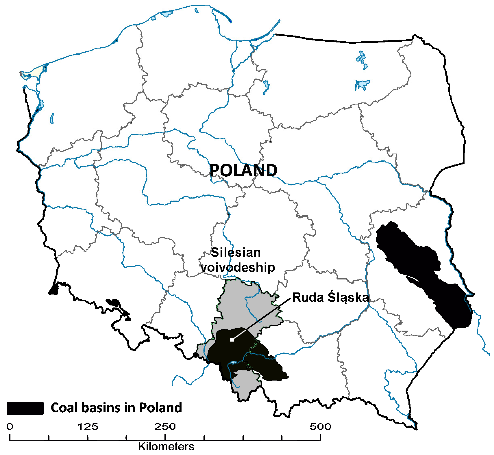
In Upper Silesia (
Figure 1), there are many areas where mining waste was deposited (
Figure 2). A unique feature of the landscape created due to mine activity is the high dumps that cover large areas [
3]. Currently, efforts are being made to revitalise this type of area, and the construction of industrial facilities there is a perfect solution from the point of view of sustainable development [
3,
4]. Areas previously treated as wastelands become areas of economic activity that greatly influence the development of a given region [
5,
6,
7]. It is no wonder then that these sites, after their reclamation, become special economic zones, which constitute a crucial role in resources for cities and regions on which their income depends [
8].
The dumps created due to post-mining waste storage are most often composed of materials that, after being properly compacted, can constitute a good ground on which construction objects can be safely found. This is due to their granulometric and mineralogical composition. Very often, post-mining waste is used to fill local depressions of land, which are the result of various types of open-cast mining (sands, aggregates, clay mines for ceramics, etc.) or deformation of the terrain resulting from deep mining. The problem that the building structure designer must solve is a very changeable state of compaction of the materials that make up the dumps or the filling of cavities. That changeability makes it impossible to estimate parameters characterising the resulting subsoil, which are indispensable to design the foundation correctly. The dumps’ material is defined as non-construction embankments, formerly also known as uncontrolled embankments. Hence, there is a need to use effective methods of soil improvement that allow one to obtain a homogeneous and adequately firm subsoil that will safely take the pressures transmitted through the foundations and the surface structures of industrial floor roads and parking lots.
Although most post-mining dumps, if properly treated, can have very good strength and deformation properties, chemical contamination is a frequent problem [
9,
10]. It is common for dumps to contain heavy chemical elements that can threaten humans. Groundwater contamination is also often observed. In this case, it is necessary to remediate the harmful substances. Of course, it should be remembered that the requirements for harmfulness to the environment for industrial areas are less restrictive than for sites intended for residential development or recreational areas [
7].
Yet another problem in post-mining land reclamation is the problem of self-ignition. Due to the presence of coal in the form of various granules and other substances (e.g., pyrite), there is a risk of spontaneous combustion [
11]. For this to occur, favourable material of dumps, embankments, or fillings of ground cavities must have access to oxygen (e.g., contained in the air). Then endogenous fires occur, which pose a considerable threat to the safety of people in the vicinity. In the case of investing in such areas, it can cause huge material losses.
The conditions mentioned above emphasize the need for proper ground recognition in the case of industrial investments in such areas. In addition to typical in situ tests used on subsoil consisting of native soil, such as drilling, sounding, and laboratory testing of the collected samples, there is a need to carry out specialised tests. Examples include thermal tests, chemical tests of soil and water, analysis of the harmful effects on steel or reinforced concrete structures embedded in the ground, as well as other tests based on which it will be possible to determine potential impacts on the future object. In terms of the strength and deformation properties of the soil medium, such specialised tests can be large-scale test loads [
12], which can give a realistic picture of the characteristics of the soil medium, based on which it will be possible to predict the behaviour of an object located on soils characterised by high heterogeneity.
Investment in development of post-mining areas will require the use of appropriate soil improvement. It should be noted that a complete soil replacement is impossible, mainly due to the very high costs (vast volumes of soils, which would have to be removed and replaced with grounds of suitable properties and developed, such as construction embankments), as well as the enormous burden on the natural environment. Hence the need to use effective soil improvement methods that will allow the proper preparation of the subsoil under the foundations while leaving the soil at the place of its deposition.
The subject of the analysis is the post-mining area in Ruda Śląska located in the south of Poland (
Figure 1). According to the decision of local government authorities, the site is intended for industrial investments, which will include the construction of production, service and warehouse halls with accompanying road infrastructure and utilities. For many years, this area was where coal mining waste was stored. As part of the reclamation process, it is currently planned to make investments to restore the site to use, which will contribute to the region’s economic development.
2. Physical and Mechanical Characteristics of Post-Mining Waste Dumps
The materials stored in the dumps are essentially waste from the coal mining process. In terms of the geological structure, these materials are a mixture of coal shales, clays, sandstones, and mudstones and they contain large amounts of overgrowth [
13]. Often in the dump mass, there are large amounts of coal that have not been separated due to the limitations of the technologies previously used for processing the extracted raw material. Therefore, in the present shape of the heap, they form unburnt (black) or burnt (red) materials. The material created after burning is characterised by much better strength and deformation properties; however, the dumps consisting of this type of material have already been mostly dismantled. This was due to numerous investments (especially road investments), where the pile material was perfect for constructing road embankments and pavement structures [
14,
15]. Black slate is characterised by much worse mechanical properties and, moreover, is very sensitive to the influence of water and other atmospheric factors [
16].
The subject of the analysis presented in the article is a dump located in Ruda Śląska (Poland, Silesian Voivodeship). It arose in the place of the former mining excavation from which clay was obtained for the needs of a brickyard. The material used to fill the excavation is coal waste from mining and energy companies. The fire hazard in the area in question has been evidenced by the example of the neighbouring area, located approximately 500 m to the south, at Bukowa Street (
Figure 3). The conditions in this area are very similar. In the past, an excavation was created after clay exploitation (to the depth up to approximately 20 m), which was filled with mining waste from the Wawel Coal Mine. The sublevel dump established there from 1995 to the present day shows a thermal activity of variable intensity over time [
17]. The research carried out in 2020 showed that there were places within the dump where the temperature exceeded 290 °C at a depth of 1 m. The ad hoc measures taken during those years to eliminate fire did not produce the desired results, effectively blocking the possibility of investments in this area.
In the area under study, no visible symptoms characteristic of self-heating of the material collected were found, such as evaporation from the dump surface, characteristic smell, distinct vegetation anomalies among plants, etc. Within the exposed areas of the waste rock on the dump, there was no so-called red slate that would confirm past thermal activity.
In the area under scrutiny, where the maximum thickness of the deposited coal waste is 19 m, the Panatonni company is building two production and storage halls with accompanying infrastructure. A series of penetration tests (
Figure 4) were performed to identify the subsoil, including drilling, static and dynamic probing [
18,
19].
The anthropogenic formation massif in the area under study is mostly made up of post-mining waste in the form of slate and stones. A representative cross section of the dump is shown in
Figure 5. The most important parameters characterising the physical and mechanical properties of these materials are presented in
Table 1.
The values presented in the table above indicate a substantial differentiation, both in the physical and in the strength properties of the materials collected in mining heaps and dumps. This is the result of very large differences in the mineralogical and granulometric composition of the deposited material and a very variable state of compaction. It is visible in the results of dynamic sounding through the dump massif (
Figure 6). This situation is the result of an uncontrolled accumulation of waste from production processes because the purpose of depositing waste materials was only to collect them in a given place in such a way so as to accumulate the most significant possible volume of waste with the smallest possible area occupied by this dump. The projects of this type of waste storage facility mainly focus on the stability of slopes, so there is no risk of failure or catastrophe causing extensive damage and transformation of the area near the dumps. Indeed, no one had predicted that in the future, construction investments would be carried out on this type of land, which would be associated with the requirement regarding specific properties of the ground on which it would be possible to safely erect, e.g., industrial facilities. It should be noted that the biggest problem, which had a decisive impact on the selection of the optimal improvement method, was not so much the presence of weak soils but a very large heterogeneity of the dump mass. A significant problem in implementing construction investments in these areas is the variable topography, which is characterised by the presence of slopes with sometimes steep inclination. This necessitates the performing of an extensive range of earthworks, which raises some logistical issues and is also very time-consuming and expensive [
20].
When analyzing the properties of slate and stones that make up the masses of anthropogenic embankments, the possibility of the presence of both very coarse stones and rock crumbs and the content of fine particles (silt and clay) should be noted. The exact grain size distribution of the soils lying on the dump depends on many factors that can influence it. In particular, attention should be paid to the phenomenon of material sticking (crushing into fine fractions) to which black shale is mainly susceptible [
9,
22]. The particle size distribution greatly influences the filtration properties, which are described by the value of the Darcy permeability coefficient. In terms of mechanical properties, a reasonably high cohesion may be important, resulting from the phenomenon of wedging of large grains with sharp edges. This type of grain shape, combined with high compaction, can result in very high values of the angle of internal friction, which is the most important parameter characterising the bearing capacity of the subsoil.
The carbon content is also very varied, and especially in old dumps, it can even reach several dozen percent [
9]. This factor, in combination with the specific content of other elements and compounds (e.g., pyrite), with adequate air access, may cause serious problems related to the occurrence of endogenous fire and other processes that transform the massif of dumps [
23]. The above phenomena are extremely unfavourable and can lead to major breakdowns or construction disasters. The loss of matter as a result of material burning through causes the formation of gaps, hollows, and sinkholes (
Figure 7), which significantly deteriorates the bearing capacity of the soil.
In some areas, the composition of the dumps was found to contain ashes which are the products of the combustion processes of the materials forming the dumps. In the course of recognition of the ground conditions, the occurrence of areas where ashes constitute the majority of the volume of dumps was found; at the same time, there are places where the presence of these materials was not observed. The ashes on the said dump in Ruda Śląska, compared to the shale described above, are characterised by a much finer graining. This property is advantageous because of the sealing of the embankments and the limitation of air access, which reduces the risk of fire. However, a characteristic feature of ashes is their very low density. As a result, they have much poorer strength and deformation properties, and it is also much more challenging to compact such soils, the behaviour of which is similar to that of silty sands or silts. It is also visible, for example, in the results of CPT static soundings (
Figure 8), whereby in the places of ash deposition, a much smaller resistance can be noticed under the probe cone. On the other hand, ashes are characterised by greater homogeneity, making them more predictable in assessing the properties of the ground on which construction objects will be erected. In addition, ashes can be used for the classification of coarse-grained materials and aggregates, which can allow the acquisition of a subsoil with very good mechanical properties in the context of taking over the impacts transferred by foundations.
The materials collected in the dumps were successfully used primarily to construct embankments and lower layers of pavement structures. Sometimes, they were also used in hydrotechnical construction and general and industrial construction [
6,
24,
25,
26,
27,
28]. However, as part of the reclamation of post-mining areas, it is also necessary to develop methods for generating investments and establishing facilities in the areas of leveled dumps.
3. Threats Related to the Occurrence of Self-Ignition of Mining Waste
3.1. General Characteristics
The mining waste from hard coal mines contains significant amounts of combustible components. The applied mechanical processing, whose task is to separate the coal from the gangue, does not ensure complete effectiveness. In addition to gangue, coal waste contains a significant amount of carbonaceous material. Carbon in waste occurs in various forms, i.e., overgrowths, incrustations in other rocks, or portions left out in the enrichment process. It can also occur as a dispersed carbonaceous substance in rocks such as coal shales (sapropel and humus) and coal clays. The carbon content in the waste currently produced in mines is several per cent. However, the value in waste that went to dumps was up to 30% in the past.
Furthermore, coal waste contains pyrite, as mentioned above, whose share in waste deposited in the past in dumps reached even 8% [
9]. In contact with the oxygen in the air and water, these components react exothermically, causing the temperature to rise. Under favourable conditions (enough active substance and the possibility of heat accumulation), they lead to spontaneous ignition and thus endogenous fire. The coal self-heating phenomenon is complex, but it has been widely described in the literature in [
11,
23,
29,
30,
31,
32] and many others. The cause of the ignition of the coal waste dump may also be external causes related to the source of high temperature (exogenous fire). Usually, it results from human activity, e.g., as a result of lighting fires, burning grasses, poorly protected welding works, pouring hot power slags, etc. Exogenous fire can also rarely occur due to lightning strikes [
33].
Regardless of the reasons for dump fire, it causes many negative phenomena that affect the natural environment and neighbouring residential areas, such as:
- -
emission of toxic and greenhouse gases into the atmosphere;
- -
dust emission to the atmosphere;
- -
fragrance discomfort;
- -
contamination of soil and water;
- -
degradation of the ecosystem (fauna and flora);
- -
thermal transformations of waste;
- -
limitation of safety for people and animals (possibility of burns and poisoning);
- -
negative impact on the landscape;
- -
loss of valuable area.
The thermal state is critical for the possibility of construction on the embankments formed from coal waste. The thermal activity of the area makes it impossible to build objects there. Burning the combustible parts contained in the waste causes the loss of matter, thus creating voids. It affects the compaction and load-bearing capacity of the soil. As a result of fires, fissures, basins, and even sinkholes are formed on the surface of the embankment. The burnt waste material is heterogeneous—from loosened to solid and hard sinter. Fires occurring on the embankment slopes significantly reduce slope stability. In the case of steep slopes with a pitch of more than 30°, fire increases the risk of slope instability. The high temperature in the thermally active zones, even exceeding 700 °C, even at shallow depths of 1–2 m [
34], poses a threat to the safety of people and the existing structures. When thermal phenomena begin, preventive measures should be taken as soon as possible. Before planning and designing, the thermal condition should be assessed in the area where the coal waste is located. If the site does not show thermal activity, it is nevertheless advisable to apply fire prevention to reduce the risk of spontaneous combustion in the future.
3.2. Methodology of Thermal State Assessment
This research aimed to search for temperature anomalies on the surface of the area under study. Infrared measurements were taken along the slopes and on the flat surfaces of the construction site. The tests were carried out using a thermal imaging camera mounted onboard an unmanned aerial vehicle and a handheld camera. Thermovision made it possible to observe the temperature field on the entire surface of the area under scrutiny. The analysis of the temperature fields marked in infrared made it possible to assess the current thermal condition and select the locations of the measurement points as part of periodic monitoring.
The following equipment was used for the tests:
- -
DJI Matrice 210V2 unmanned aerial vehicle;
- -
DJI Zenmuse XT2 optical and thermal camera;
- -
Flir E6 thermal imaging camera;
- -
KESTREL 4500 multifunctional device (measurement of meteorological parameters).
3.3. Results and Discussion
The tests were carried out on 7 July 2021. Thermal imaging tests were carried out at dawn (4:20 a.m.–5:45 a.m.) to minimise the influence of solar radiation on the surface temperature. The following meteorological conditions prevailed at that time:
- -
air temperature: 20.0 °C;
- -
reflected temperature: 20.0 °C (assumed value);
- -
relative humidity: 65.5%;
- -
pressure: 994.5 hPa;
- -
no cloud cover;
- -
weak wind;
- -
no rain, also on the previous day.
Infrared research allowed us to obtain thermograms showing the temperature distribution of the terrain surface. Each thermogram was analysed. The results are presented in the tables in
Figure 12 and
Figure 13. Within the separated zone, the maximum, average, and minimum values were determined, and additionally at three selected points. For the presentation of the test results, only exemplary thermograms are provided. Visible images are also attached (
Figure 12 and
Figure 13). No visible external symptoms of self-heating of coal waste were observed within the area under study. The surface condition did not differ from the typical condition for such facilities at this time of year.
Infrared surface temperature measurements did not reveal any temperature anomalies indicative of thermal activity. Surface temperatures in the area under scrutiny were mainly lower than or close to the ambient temperature (20 °C). The maximum values of the surface temperature ranged from 14.8 °C to 23.6 °C. The area immediately adjacent to the south side of the area in question did not show elevated temperature values either.
3.4. Thermal Condition Monitoring
The lack of thermal phenomena in the area under study does not guarantee that they will not occur in the future. The example of the site mentioned above (on Bukowa Street) showed a risk of spontaneous combustion in this type of area.
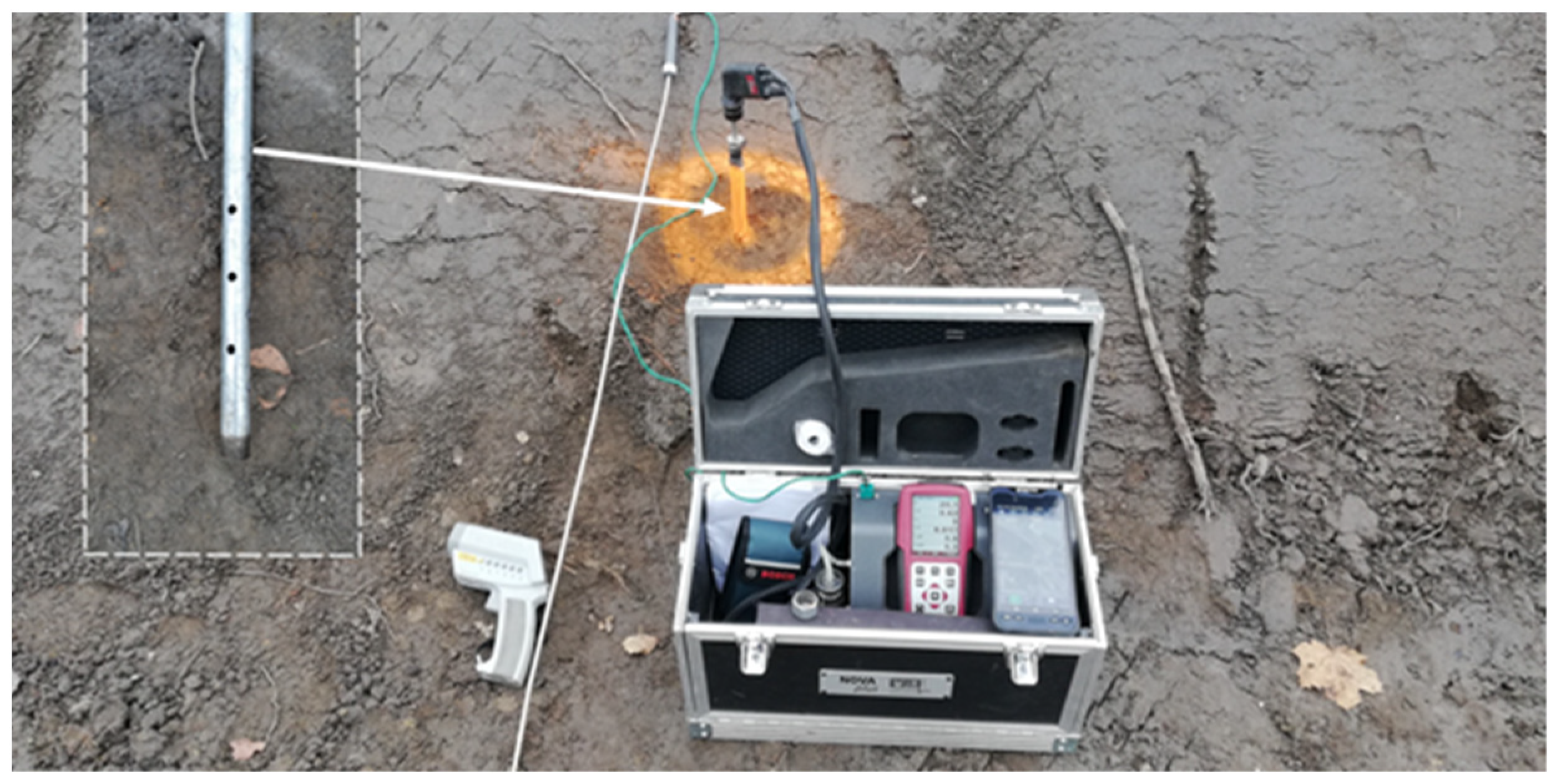
The introduction of monitoring made it possible to control the thermal condition during the construction and operation of the investment. The location of five points of periodic thermal and aerological control was proposed. The location of the points was related to the areas of large thicknesses of the coal waste embankment, where there are better conditions for self-heating because of the higher carbon content and the possibility of heat accumulation generated in the process of its oxidation. It was pointless to locate the points where there were thicker layers of waste from the power plant (fly ash or slag). Openings 1.0 m deep were made in which perforated steel pipes with a diameter of ½ inch were mounted. The surface temperature (t
p) of the embankment was measured in the vicinity of the points using a pyrometer. After the atmosphere stabilised inside the measuring tubes, the temperature (t
1m) of the coal waste that forms the embankment was measured. The concentration of essential gases (O
2, CO
2, CO, CH
4) was measured using the MRU-Nova+ gas analyser at a depth of 1.0 m. Based on the oxygen concentration found at the measurement site, the oxygen loss (∆O
2) was determined, taking onto account the oxygen concentration in the natural composition of atmospheric air (20.9% vol.). One of the monitoring points with measuring equipment is shown in
Figure 14.
The results of examining the embankment’s interior at the measurement points P1–P5 obtained during the first measurement session also did not indicate the presence of thermal phenomena. Temperature values at a depth of 1.0 m were within a narrow range from 8.4 to 10.7 °C. Gas concentrations were in the following ranges, respectively:
- -
oxygen O2 from 11.5 to 20.9% vol.
- -
carbon dioxide CO2 from 0.04 to 0.65% vol.
- -
carbon monoxide CO from 0 to 2 ppm
- -
methane CH4 from 0 to 0.02% vol.
Thermally active zones on heaps can be characterised by different temperature values and gas concentrations depending on the development phase of coal self-heating [
30]. During self-heating, the temperature of the material may exceed 100 °C, and in fire conditions it may reach 1000 °C [
29]. The results of the measurements summarised in
Table 2, especially the reduced oxygen concentrations at points P4 and P5, indicate the occurring processes related, among other things, to the oxidation of the carbonaceous substance contained in the analysed embankment. However, no thermal anomalies were observed as part of this phenomenon. The temperature values of the embankment surface at the surveyed points were even and below the air temperature, which was 8 °C on the day of measurement. The temperature measured in the measuring tubes at a depth of 1 m was also characterised by low values. This indicates that the current carbon content in the rock mass is low, or the intensity of oxidation and the amount of heat released during the reaction is negligible.
4. Technologies for the Improvement of the Subsoil Built of Anthropogenic Materials
As described in detail in
Section 2, the problem that engineers must solve when investing in post-mining dumps is to ensure proper ground preparation for the foundations of structures or pavement structures. The improvement technologies used should, in particular, make it possible to obtain a subsoil with homogeneous strength and deformation properties. On the other hand, the small load-bearing capacity and stiffness of the subsoil should ensure the limit conditions of the ultimate and serviceability limit states of the object foundation, which guarantees an appropriate safety margin.
The subsoil for industrial buildings should guarantee the safe transmission of loads in the range of 200–300 kPa, which most often occur under the footings of the columns that make up the supporting structure of the facilities.
In case of an increased load or the presence of a weaker subsoil, the surface area of the foundation should be appropriately increased. In addition, the stiffness of the substrate is also significant. It is required that the settlements be no more than 5 cm, which means that it is necessary to obtain sufficiently high values of the stiffness modulus of the soils lying in the ground. However, much more important from the point of view of foundation displacement are the quite strict requirements for homogeneity of settlements (according to Eurocode 7 [
35], relative differences in the settlement should not exceed, depending on the object’s function, the value 1:150–1:500). High stiffness of the subsoil is also required when designing industrial floors in the ground. The structures of these floors are usually concrete structures with traditional reinforcement or more and more often dispersed reinforcement. When the subsoil is too soft or when the difference in stiffness between individual parts under the slab is too large, scratches or unfavourable deformations of the slab surface may occur, the use of which will be very difficult.
Considering the characteristics of the soils that build the ground and the requirements for the subsoil beneath the foundations, it can be concluded that the most effective and efficient soil improvement methods are technologies based on soil compaction. It is important that the depth of the improvement is large enough to allow the compaction of deeper soils. Often there is a need to compact the materials deposited on their bottom. Hence, there is a need to use high energies, due to which the gain range is sufficiently large. Using the known Menard formula, the depth of compaction caused by the drop of a heavy rammer can be estimated based on an empirical relationship [
36]:
where
k is the coefficient depending on the type of subsoil; for post-mining dumps, it can be assumed that
k = 0.5–1.0;
hz is the effective range of compaction improvement [m],
M is the mass of the dropped rammer [Mg], and
H is the height of discharges [m].
One of the most effective technologies for the improvement of this type of soil, which is characterised by a significant heterogeneity, is dynamic compaction. It consists of dropping rammers weighing up to 20 Mg (and more) from a height of 15–20 m [
36] (
Figure 15). Due to this, based on Formula (1), it is possible to improve the subsoil to a depth of more than 15 m. This method is perfect for improving the materials lying in coal waste dumps. In addition to increasing the degree of compaction, its greatest advantage is the possibility of obtaining a homogeneous subsoil, which is a crucial issue in the construction of industrial facilities in reclaimed areas. Depending on the thickness of the deposited anthropogenic soils and the requirements in terms of bearing capacity and stiffness of the subsoil, the weight of the rammer and the discharge height can be selected so that the applied improvement is optimal. A serious disadvantage of dynamic compaction is the generation of ground vibrations, which are harmful to nearby buildings or infrastructure elements [
37,
38].
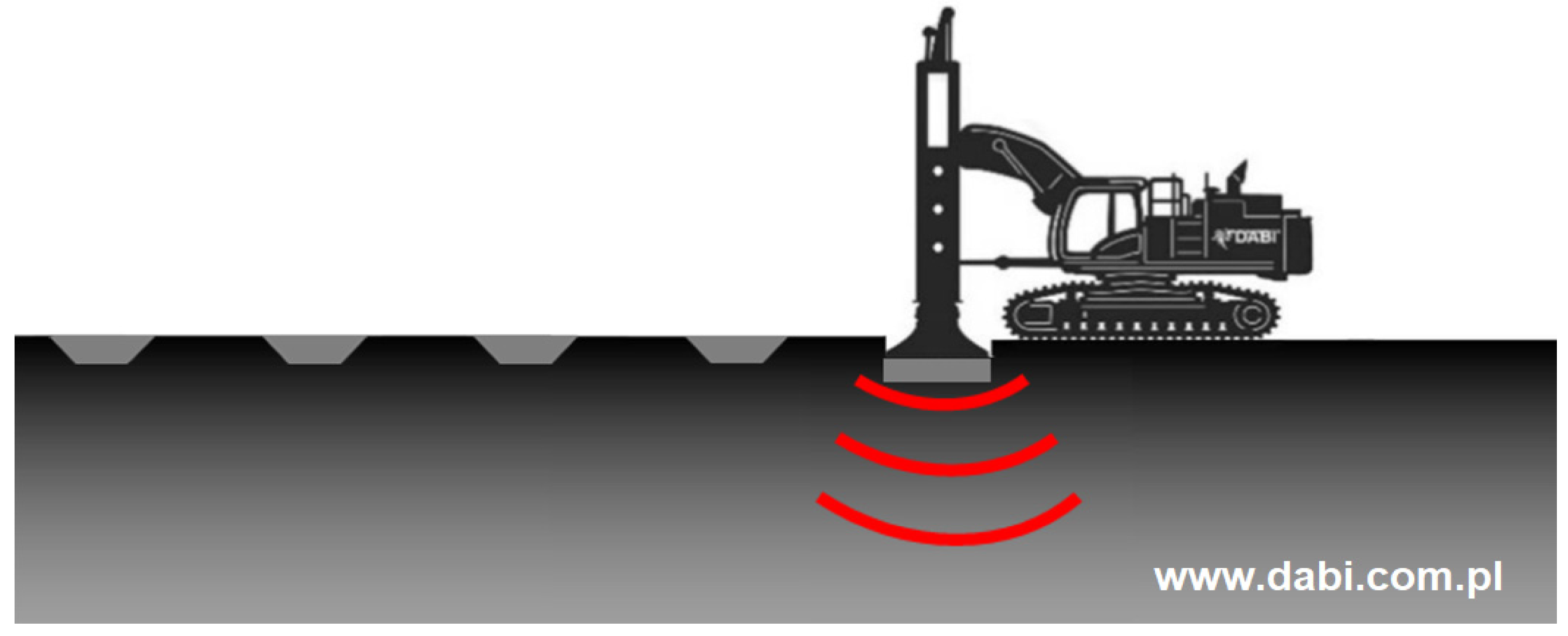
In the case of more minor soil (waste) thickness that requires compaction, RIC (Rapid Impact Compaction) technology can be used instead of the above method. This method uses the same principle of soil compaction due to the energy of the compactor falling onto the ground. The difference is the falling height of the rammer, which is approximately 1.2 m, and the method of its discharge. In the case of the RIC method, discharges are made using a rigid guide instead of the free fall used in the Menard compaction. Due to this, the rammer falling frequency is up to 20–40 beats per minute, which significantly accelerates the implementation of works. The mass of the dropped rammer in the RIC method is approximately 10 Mg, and the rammer itself falls not to the ground but to a rigid steel plate (
Figure 16). The RIC method allows for the effective compaction of the subsoil up to several meters below ground level [
39,
40], sufficient for most industrial investments. Moreover, the advantage of the RIC is the possibility of large control of the plate rush after each impact of the rammer, which will allow the evaluation of the effectiveness of compaction already at the stage of execution of the works. The lower discharge energy in the RIC method (compared to the classic Menard dynamic compaction method) often translates into a smaller range of the impact of vibrations generated by the drops [
41].
If there are layers or lenses of cohesive soils in the dump massif, it is possible to make driven stone columns (DR technology—dynamic replacement). In the case of cohesive soils, as a result of the discharges, a large-sized crater is struck, which is then filled in with stone material with thick crumbs (
Figure 17). Subsequent rammer discharges compact this material and create stiff stone columns that improve the weak soil. It should be noted that the use of stone columns in the case of post-mining dumps can be treated as a complementary technology (for dynamic compaction) without a detailed separation at the design stage. In the case when craters are so small that after the completion of the compaction, it is possible to level them with a bulldozer and compact the terrain surface with a heavy roller, we are referring to the classic technology of dynamic or impulse compaction. However, when the formed craters are too deep, each time they should be filled with appropriate aggregate.
The choice of technology for the execution of stone columns depends primarily on their desired lengths. Columns with the length of up to 3 m can be successfully made using the RIC impulse compaction method, whereas if it is necessary to form columns longer than 3 m, the DC heavy compaction method should be used. The depth of column formation is proportional to the applied energy and the thickness of the weak soil. The advantage of heavy compaction is the much greater energy of a single drop, due to which even columns with the length of 6 m can be formed.
However, the increase in energy translates into a greater propagation of vibrations, which may be a significant problem for the buildings in the vicinity. The creating of stone columns by the RIC impulse compaction method causes relatively much lower vibrations and several times faster work performance than the traditional DR method. However, a serious limitation of the RIC method is the ability to generate energy not exceeding 10 Mg·m, which means that the maximum range of the formed columns is approx. 3 m.
In addition to the methods described above, which enable the compaction of dumps consisting of post-mining products, there are also many other possibilities for the foundations of industrial facilities. The construction of gravel or cement-ground columns are an example. Among the latest technologies, jet-grouting or deep-soil mixing columns are worth considering, where they are obtained by mixing cement slurry with the soil existing in the subsoil. These methods use the excellent properties of the dump material as a component of the ground cement. Results of such treatment may be easily controlled [
42]. Sometimes, however, there may be a problem with the implementation of the columns, mainly when the dump mass includes thick rock crumbs, which make it difficult or sometimes impossible for the proper operation of the column equipment, and in extreme cases even cause its destruction. It is also possible to place the structures of the facilities on piles; however, this type of procedure is certainly not an optimal solution due to costs which can be avoided, as the soils forming the dumps have relatively favourable mechanical properties, provided proper compaction is ensured. Moreover, pile execution is very difficult due to the grain size distribution, and some pile forming technologies (such as driving) cannot be applied. New technologies concerning both reuse of coal dumps and control of the treatment are still under development. Deformation susceptibility test results of mixtures of coal mining waste and recycled tire rubber bound with the use of hydraulic binders can be found in [
43].
In the case of industrial floors, in which relatively low loads (compared to foundation feet) are transferred to the ground, it is necessary to obtain very stiff ground, which guarantees proper static work of the slab. For this reason, geomattresses are often used, consisting of a layer of sharp-edged aggregate mechanically stabilised with geogrids. In the case of fine-grained soils (e.g., ashes) or cohesive soils in the upper part of the subsoil, stabilisation with hydraulic binders can be used instead of geomattresses [
44]. This stabilisation consists of mixing the top layer of the soils with a thickness of approx. 40 cm with a binder using a recycler, which will make it possible to obtain a very stiff layer that improves the subsoil under the floor slab.
5. Construction of the Panattoni Industrial Halls in Ruda Śląska
An example of a successful industrial investment in former post-mining dumps is the construction of two Panattoni warehouse, service, and production halls in Ruda Śląska at 1 Maja Avenue and Gurtler Street (
Figure 18). The usable area of the halls is 46,125 m
2 and 24,530 m
2. The general contractor for the construction works was Kajima Poland Ltd., Warszawa, Poland. The structure of the halls consisted of columns fixed on the spread footing, which were joint supports of the steel truss structure of the roof. As part of the ground preparation under the foundations, the contractor performed RIC impulse compaction in the area where the dump mass was dominated by lumpy waste resulting from coal exploitation. It constituted almost the entire area under the smaller hall and most of the area for future roads and parking lots. However, in places where ash was deposited on the surface of the ground after macro-leveling to the designed level of the construction work, stabilisation with cement was used to improve the ground. Due to significant differences in the ground level resulting from the shape of the post-mining dumps, macro-leveling of the area to the ordinate of impulse compaction works was necessary (
Figure 19).
Impulse compaction was carried out on an area of approx. 42,000 m
2. Rammer drops were made at points arranged in a grid of equilateral triangles with a side length of 3.0 m. Basically, for an effective ground improvement, it turned out to be sufficient to make two machine work passes per point, although locally in places with greater loosening of the ground, three or even four machine passes at a given point were necessary. This resulted in a total number of compaction points of approx. 9000. The machine moved from point to point according to the designed grid of points (
Figure 20). All the performed points were tracked in the GPS system, due to which the operator’s work was carried out with high accuracy. It was particularly important when performing subsequent passes of the device at a given point. In addition, the RIC impulse compaction machine was equipped with an automatic data recording system that recorded the most important work parameters on an ongoing basis, i.e., the point number with coordinates, execution time, number of strokes per point, and single and total drive of the steel compacting foot.
All works that imposed severe dynamic impact on the neighbourhood were controlled by means of dynamic monitoring of ground-transmitted vibrations. The equipment used for these measurements was a standard MINIMATE 4 PRO kit that makes it possible to control 3D vibrations and noise in the course of geotechnical works.
The measurement works were carried out in the presence of the contractor’s representative, who, due to the continuous nature of the tests, was kept informed about the results of the measurements and, if necessary, could possibly modify the impact energy of the impulse compactor on an ongoing basis. The research was conducted in three stages. The first stage on 27 May 2021 included a test measurement to determine the safe operating zone of the RIC device from the foundations, medium voltage cables and stabilization of the under-floor layers and gabions. The changes in the vibration velocity levels with the distance and proximity of the RIC device to the sensor embedded on the ground surface were investigated (
Figure 20).
Limitations of maximum vibration velocity (PPV) accompanying concrete setting were established on the basis of [
45] and in
Table 3, composed on the basis of [
46]. It must be noted that concrete composites at their early stages are “vibration resistant” but in the period of young concrete (3–12 h), one must be cautious when performing work related to large vibrations in the close vicinity.
The worst time for concrete to be exposed to vibrations is between 3 and 24 h. Looking at the attached
Table 3, it can be seen that in the key hours 3–12 from concreting, the maximum permissible vibrations (PPV) are approx. 35 mm/s. Later, for the period of 12–24 h from concreting, it may be up to 50 mm/s. The vibrations were measured on the ground surface (
Figure 20) for the distance of the machine every 2.5 m further from 5 m. During the analysis of the measurements, it was found that the resultant vibration velocities dropped from over 70 mm/s at a distance of 5 m to approx. 20 mm/s at a distance of 12.5 m. For concrete and spread foundation footings, a distance of 12.5 m was allowed. Due to the large area of stabilization performed at one time and large differences in vibrations (changes with distance), it was decided to maintain a protection zone of 20 m.
Measurement 2 was performed on 10 June 2021 and its purpose was to assess the impact of vibrations on the stabilization performed for gabions of works carried out in the immediate vicinity. The diagram of the measurements is shown in the picture on
Figure 21, where the distances to the objects on the other side of the road are also marked. Vibration limits were established on the basis of recommendations given in [
47,
48].
The third measurement of vibrations focused on the assessment of the nuisance of the work carried out on the functioning of office and commercial facilities in the vicinity of the construction site. Measurement work, which were performed due to the reported nuisance regarding mechanical vibrations and noise, was carried out on 25 June 2021 at the premises of the following companies: Bellator and Novum Stone Expert.
The work was carried out at the closest location of the RIC device to the buildings in question and for the standard characteristics of the RIC device (height of the hammer drop, frequency of dynamic pulses). The minimum distances were respectively: 90 m for Bellator offices and almost 120 m for Novum Stone Expert facilities. The location of the machine during the measurements is shown in
Figure 22.
With regard to the monitoring carried out in stages 2 and 3, due to their remoteness, the levels of the recorded vibrations did not exceed the values considered safe for buildings, both for the Bellator facility and for Novum Stone Expert. The vibrations measured on the buildings were well below the safety criteria defined in standard regulations for residential buildings and even for monuments. However, due to the inconvenience for the personnel (vibrations and noise), it was agreed that the ground strengthening work at the shortest distance from the buildings would be carried out outside their working hours.
Another important issue related to rapid impulse compaction of coal dumps such as in
Figure 23 is the effectiveness measured in terms of increased stiffness of foundation.
The effectiveness of the improvement was evaluated on the basis of trial load tests applied to the subsoil by a rigid steel plate with a diameter of approximately 1.13 m and an area of 1.0 m
2 (
Figure 24). As part of the tests, the path of primary loading, unloading, and reloading was carried out. The maximum load under the plate used in the trials was approximately 350 kPa. The results obtained are the primary stiffness modules (E
1) and secondary stiffness modules (E
2) [
46]. Before the beginning of the work, a compaction test was carried out on several experimental plots located in different parts of the improved area. The test results are presented in
Table 4. It can be seen that dynamic compaction allows for more than twice the increase in the stiffness of the subsoil (locally even five times), which significantly translates into an increase in the mechanical properties of the subsoil, including its load-bearing capacity.
The designer of the hall structure assumed the need to obtain the value of the E2 module not lower than 40 MPa under the footings and 30 MPa for the industrial floor structure. Simultaneously, it is required to obtain the value of the deformation index I0 (the ratio of E2 to E1) not higher than 3.0, which translates into the minimum values of the E1 modulus equal to 13.3 MPa and 10 MPa, respectively. Considering the results obtained from the experimental plots, it could be concluded that dynamic compaction would be an appropriately effective method for improvement that would allow for the safe implementation of the planned investment.
The trials carried out as part of the acceptance tests of work related to improving the subsoil using the impulse compaction method confirmed the correctness of the carried out work [
46]. Fifteen tests were carried out. The mean value of the primary stiffness modules was 46 MPa (range of obtained results: 33.4–53.3 MPa) and the standard deviation was 14 MPa. In the case of secondary stiffness modulus, the mean value was 88 MPa (range (56.7–96.3 MPa), and the standard deviation was 24 MPa. The increase in the value of stiffness moduli E
1 and E
2 (up to 500%, approx. 250%) proves a very high efficiency of the applied method of soil improvement. It should be noted that the results obtained are much greater than the requirements set by the designer. It is worth noting the relatively low (for geotechnical work) value of standard deviations, which amounts to approx. 30%. This shows the high homogeneity of the subsoil after impulse compaction, which, compared to the very variable properties of the dump materials, shows the effectiveness of the subsoil improvement method that was used. Simultaneously, it contributes to increasing the number of possible actions for the reclamation of degraded areas. The requirement for safe work performance is monitoring, carried out both in the construction stage and during subsequent exploitation [
49,
50].
6. Conclusions
Based on the analysed example, it can be concluded that it is possible to implement industrial investments in post-mining areas where coal waste was stored in dumps [
51]. Thanks to this, degraded areas can be reclaimed, and additionally, investment areas can be obtained that contribute to the region’s development. The safe carrying out of construction work requires the development of an appropriate project, within which it is necessary to perform the proper recognition of the subsoil, and design a selection of effective technologies for soil improvement together with acceptance tests. It is necessary to properly supervise the construction work carried out and monitor the behaviour of the facility—both during construction work and the subsequent use of the construction objects.
The method of soil improvement using the impulse compaction technology presented in the article turned out to be both effective in terms of increasing parameters characterising mechanical features (load-bearing capacity and stiffness of the soil) and the possibility of obtaining a homogeneous subsoil. The stiffness modulus, which is a measure of the subsoil stiffness, was more than doubled. The variability of these modulus values did not exceed 30%, despite very large differences in the mineral and particle size composition of the material constituting the dump and its compaction state. This proves the very high effectiveness of the applied improvement method, which is often optimal for subsoil characterised by a very high heterogeneity of strength and deformation properties of the soil lying in the ground.
The design of subsoil improvement by impulse compaction is usually based on empirical data and the designer’s own experience. Due to a very large variety of properties of non-construction embankments, it is not possible to model the behaviour of soils during their strengthening.
The degree of land coverage by buildings, soil compaction within the entire construction site, and the implementation of cement-stabilized layers along the existing slopes effectively limited the access of air to the interior of the embankment, reducing the risk of self-ignition.
The results of the first measurement session as part of the thermal state monitoring, including the reduced oxygen concentrations at points P4 and P5 (oxygen loss ∆O2 amounted to 9.4 and 2.4 vol.%, respectively), indicate processes that still occur related, for example, to the oxidation of the carbonaceous substance contained in the embankments. However, the conditions in the area under study are not favourable to heat accumulation. The values of the concentrations of the remaining gases (CO2, CO, and CH4) and the temperature of the material that forms the embankment confirmed the lack of thermal activity. Thermal condition monitoring should be carried out over a longer period. Subsequent measurement sessions will be conducted in the following quarters. If a stable and safe thermal state is maintained, the period between measurement sessions can be extended to six months, and an annual inspection will still be sufficient.


 ,
, 


