Article

The Characteristics of the After-Combustion in a Commercial CFBC Boiler Using the Solid Waste Fuel

1
Greenhouse Gas Laboratory, Korea Institute of Energy Research (KIER), 152 Gajeong-ro, Yuseong-gu, Daejeon 34129, Korea
2
Graduate School of Energy Science and Technology, Chungnam National University, 99 Daehak-ro, Yuseong-gu, Daejeon 34134, Korea
*
Authors to whom correspondence should be addressed.
Energies 2022, 15(15), 5507; https://doi.org/10.3390/en15155507
Submission received: 23 June 2022 / Revised: 26 July 2022 / Accepted: 26 July 2022 / Published: 29 July 2022

Abstract

:
A CFBC (Circulating Fluidized Bed Combustor) boiler for combusted SRF (Solid Refused Fuel) is designed for solid waste combustion and power generation. The boiler consumes about 200 tons/day of SRF and generates 60 ton/h of steam or 10 MWe in electricity. The boiler is designed to burn pelletized waste fuel made of municipal solid waste collected from a town with a population of 400,000. Heat and mass balance calculations over the combustor and at each boiler section were performed and compared between the designed and measured data to analyze the boiler’s performance. After-combustion, the most significant phenomenon in low-density waste-derived fuel combustion in a CFBC boiler was monitored. The heat and mass balance were the most appropriate tools to analyze the boiler performance. The flow rate of spray water at the de-superheater was a reliable indicator to quantify the after-combustion. The design modification of the boiler unit for after-combustion control in the existing boiler was based on the quantification of spray water. The load distribution of the de-superheater decreases from 1.76% to 0.87% in 89% MCR before the installation of the evaporator and 82* % MCR load distribution of each boiler part after installation. The result was effective for the control of after-combustion in the existing boiler.

1. Background

The energy conversion of solid waste is one of the biggest issues in modern metropolitan life and government administration. Instead of using simple incineration or landfills, converting waste to solid fuel and combusting it in a designated combustor is acknowledged as an improved concept for both safety and energy saving considerations [1,2,3]. The Korean government has also made significant efforts in municipal waste utilization, especially thermal energy conversion [4]. So far, the regulations regarding manufacturing waste-derived fuel and emissions as a result of combustion have been well prepared. Several promotions regarding SRF (Solid Refused Fuel) manufacturing and its thermal utilization have been launched [5]. CFBC of waste-derived fuel showed higher combustion and boiler efficiency than other technologies [6,7,8]. A steam 60 ton/h CFBC combusting pelletized SRF was designed by the authors to demonstrate the energy utilization of municipal solid waste [9]. The boiler was constructed using parameters from previous results of lab and pilot scale studies [9,10,11].
The operational characteristics of SRF combustion in conventional boilers share most parameters yet are different in several significant points from the boilers combusting conventional solid fuel. First, Figure 1 shows the density of sloid fuels; the fuel manufactured from SRF is lighter in density, and it contains more volatile components than conventional coal. Its ignition and combustion start faster than coal, but it flows in the combustor region with the flue gas, resulting in the after-combustion phenomenon in which the combustion reaction continues.
Until 2019, solid waste fuel combustion in power generation was mainly focused on the study of the co-combustion of coal/SRF. Authors have studied the co-combustion of coal and SRF. The most important factor that influences this process is the composition of alternative fuels. Using the SRF instead of coal in the co-combustion process helps to preserve natural resources, limiting the use of fossil fuels and reducing the impact on the environment through lower CO2 emissions. However, SRF combustion is the main part of small-scale commercial combustion, and it shows different combustion characteristics from co-combustion. Therefore, the problem of after-combustion due to the characteristics of SRF has begun and related research is needed [12]. When SRF is combusted in a CFBC, the density of the circulating material inside the combustor has a great influence on solving the after-combustion generation. The combustion characteristics and heat transfer of SRF fuel in CFBC are affected by the fuel and circulating material. For this purpose, the study of CFD (Computational Fluid Dynamics) simulation according to the density and diameter of circulating materials in a fluidized bed reactor is proceeding. It is reported that the number of heat transfer coefficients increases when the density of the circulating material increases in the fluidized bed reactor [13]. SRF has less ash content than coal fuel, which is characterized by low solid density in the fluidized bed reactor. For this reason, the low heat transfer coefficient should be applied compared to coal [14,15].
In a CFBC boiler, the cyclone region including the furnace is called the combustor, and the combustion reaction generated between the convection pass from the cyclone exit is called the after-combustion. Second, it contains a higher level of mineral salts, K/NaCl, as they have low melting temperatures and easily stick to superheater tubes in the convection pass, forming hard deposits or fouling [16,17]. When the combustion zone is extended to the heat recovery zone, such as the convection pass, potential damage by these compounds to the boiler tube material is increased [16]. The waste fuel combustion boiler must provide high combustion and boiler efficiency, yet it should not damage the boiler material. Thus, the basic design and operation philosophy is that combustion should not extend to the combustor outside. However, in cases where the design is fixed or the fuel property varies, it is difficult to control this by adjusting the operation parameters only [18]. For performance enhancement and upgrading, a quantified understanding of boiler performance is necessary, and modifying the design according to the data is essential [19].
This study introduces the monitoring and analysis results of a 60 ton/h CFBC, which was built by domestic design and engineering in Korea [9,10,11]. The purpose of the work was to set up a reliable approach to boiler performance measurement. To do this, heat and mass balance equations were set up at each boiler to analyze their performances individually. This was applied to the quantitative analysis of after-combustion, which is prevailing in solid waste fuel combustion in CFBC. The results were compared with the measured operation data such as the flue gas temperature, boiler load, and thermal capacity of each boiler unit. The engineering parameters obtained through the heat and mass balance were applied to the design of the modification unit of the existing boiler. The result was compared with the previous operating conditions to prove the improvement of the boiler performance.

2. Experimental

2.1. Dimension and Condition of Boiler
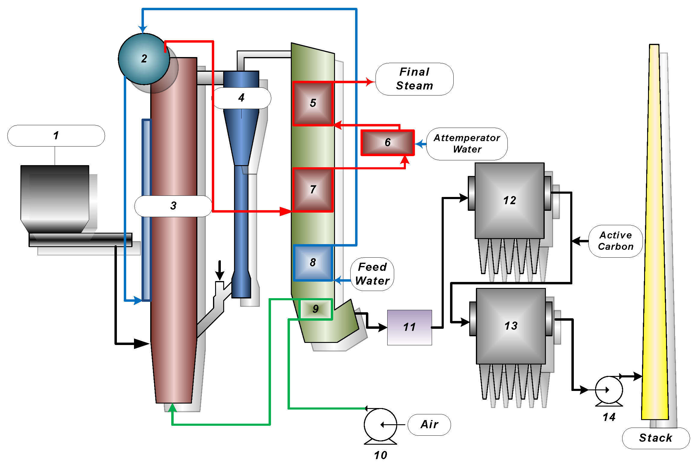
This CFBC boiler with a 60 ton/h steam flow and a concept similar to the conventional CFBC coal boiler is composed of a combustor chamber, a single cyclone, a convection pass, and two bag filters [10]. Figure 2 shows a diagram of the commercial CFBC boiler system. The combustor is a tall vertical square column with wall dimensions of 4 m × 4 m × 24 m (width × depth × height) and is surrounded by vertical evaporator tube walls. The nominal capacity of this boiler is 60 steam ton/h or 10 MWe in electricity. The design specifications of the boiler are listed in Table 1. A predetermined amount of a fluidizing material (sand) is filled in the bottom of the combustor as the initial bed content. The boiler is heated up to operating temperature by auxiliary fuel during startup. The preheated combustion air by an air-gas heater is provided through the distributor on the floor of the combustor. The fuel is fed to the lower part of the combustor over the sand bed. The start-up and operation procedures are the same as in other CFBC boilers [11].
There are three boiler units: the economizer, the evaporator, and the superheater. In order to cool overheated steam and precisely control the steam temperature, the superheater is divided into two sets of tube bundles, namely superheater 1 (S/H 1) and superheater 2 (S/H 2), and a de-superheater that controls the steam temperature by injecting water is designed to be in between them. An evaporator is located at a water wall tube panel surrounding the combustor. The superheaters and economizer units are all located in the convection pass. The air-gas heater is also located in the lower part of the convection pass, which is downstream of the flue gas. Since heat recovered in the air heater only increases the heat content of the combustion air and the added heat goes to the combustor flame side, the air heater is not a part of the boiler but of the combustor unit.
The combustor side flow circuit is shown below:
Fuel from fuel feeder → Combustor → Cyclone → Convection pass → Air heater → SDR (semi-dry reactor for SOx and HCl absorption) → Bag filter 1 → Bag filter 2 → Stack.
The water and steam circuit are shown below:
Water from BFWP (boiler feed water pump) → Economizer → Steam drum → Down-comer → Water wall evaporator → Drum → Wall superheater → S/H 1 → De-superheater → S/H 2 → Final steam exit.

2.2. Boiler Design

The SRF fuel used for this boiler is shown in Table 2. This 60 ton/h CFBC boiler was designed to burn only fuel derived from municipal waste. The properties of the test fuel are similar to the design fuel. The meaningful differences between the low test fuel and high test fuel were the heating value, water, and ash content. This waste-derived fuel was a pelletized type, but the bulk density was lower than that of the designed fuel by over 40%, indicating that a larger amount of light-density fluff is contained.
The enthalpy of the final steam and feed water were 3335 and 601 kJ/kg, respectively. Thus, the thermal output of the boiler was 45.6 MWth in the following manner.
T h e r m a l   o u t p u t = H s t e a m H w a t e r × F e e d   m a s s
The combustion efficiency of the boiler can be calculated from carbon loss through ash. The carbon content of bottom ash was 0.05–0.06% and that of fly ash was 0.3–0.67%. The combustion efficiency was calculated by heat loss based on unburned carbon in ash. The total carbon loss from bottom ash and fly ash was 16.9/100 × (0.2 × 0.06 + 0.8 × 0.67) = 0.09%. Thus, combustion efficiency was 99.9% and is considered to be complete. The after-combustion, i.e., the extended combustion zone to the cyclone and convection pass after the combustor exit, was consistently monitored, and the phenomena were displayed as the temperature increased after the combustor exit [20,21]. Figure 3 presents that, compared with the measured and calculated temperature distribution in accordance with boiler load alongside the gas flow. The temperature profile showed the highest temperature at the convection pass inlet (S/H 2 up), indicating that a significant part of the after-combustion occurred after the combustor exit. The extent of the temperature difference was not proportional to the boiler load and thus did not relate to it, which was considered to be affected by the operation mode or fuel density, and the main discrepancy is due to heterogeneity of combustion in the combustor section. The reading of the thermo-sensor is also influenced by location, such as the steam tube and steam wall, providing false information for thermal analysis.

3. Results and Discussion

3.1. The Effect of Air Heater on Flue Gas Temperature

The main purpose of adopting the air heater in the combustion system was to provide extra heat into the combustor and thus increase the combustor temperature. A higher temperature in the combustion environment provides a better combustion and heat transfer but yields less unburned residue. However, increased air temperature over the boiler design temperature can cause an elevated combustor exit temperature, which can lead to a corrosive environment in the boiler tubes. This is common when waste-derived fuel is burned, especially when the fuel contains a high concentration of Na and K [9,22,23,24]. The flue gas temperature at the economizer downstream controls the inlet combustion air temperature. Since heat transfer is determined by the flue gas flow rate and the in and out temperatures of the flue gas,
Q f l u e , A = m a i r C p ,   a i r T o u t ,   a i r T i n ,   a i r
where Q f l u e ,   A is the heat exchange of flue gas over air heater, m a i r is the mole flow rate of air, C p ,   a i r is the heat capacity of air, T i n ,   a i r is the inlet temperature at the air heater, and T o u t ,   a i r is the outlet temperature at the air heater.
From the designer’s point of view, control of the combustor exit temperature is essential because if it is higher than the design range, it may damage the boiler material, including the steam tubes, whereas if it is lower, the combustion may not be complete inside the furnace, which would yield more CO and carbonaceous residue. The general design condition of combustor exit temperature is known to be between 800 and 900 °C [20,25].
Figure 4 presents the effect of the economizer downstream temperature on the air temperature at the air heater exit and the flue gas temperature at the combustor exit. The data was calculated by assuming a fixed heat input into the combustor by fixed fuel and the flow rate of primary air and also the fixed heat extraction rate water wall. The results of the measured and calculated temperature were similar within the margin of error. The air temperature at the air heater exit increases linearly according to the flue gas temperature because C p ,   a i r is almost constant in this temperature range. Furthermore, the combustor exit temperature varies linearly with the inlet air temperature because the combustion air provides additional heat into the combustor. The air temperature at the outlet of the air heater is easy to predict, but due to the heterogeneity of solid fuel combustion, it is difficult to predict the value with precision.

3.2. Non-Homogeneity in Combustor

Predicting the average combustor temperature by monitoring the temperature sensor is impractical due to the heterogeneity of the combustion inside the combustor. The combustor exit temperature shows neither reliable precision nor a trend with the calculated temperature. Considering that the combustion inside the combustor is not uniform because the particle density inside the combustor varies vertically as well as horizontally, the local temperature is different corner by corner. When the temperature at the exit was compared with the cyclone exit temperature, there was an increased temperature at the cyclone exit. This indicates that part of the unburned fuel inside the combustor section was entrained out to the cyclone exit, and the combustion continued near the inlet section of S/H 2.
Even though the heat and mass balance calculation of the temperature did not coincide with the measured temperature, it provided conceptual data on the heat distribution over the boiler section as well as a better understanding of the boiler performance over various boiler loads. The flue gas temperature at the combustor exit is calculated as follows when there is no after-combustion:
Q f u e l + Q a i r Q B A = m w H s a t H E C 0 + m m i x · T r e f T c o m b C p m i x d T
where Q f u e l is the heat input to the combustor by fuel combustion, Q a i r is the heat input to the combustor by heated air through air heater, Q B A is the heat loss by bottom ash discharge, m w is the mass flow rate of feed water, H s a t is the enthalpy of saturated steam at drum pressure, H E C 0 is the enthalpy of feed water at economizer outlet, m m i x is the mass flow rate of flue gas and fly ash mixture, C p m i x is the heat capacity of the flue gas and fly ash mixture, T c o m b is the temperature of flue gas at the combustor exit or superheater upstream, and T r e f is the reference temperature. All other values are known, so the combustor exit temperature, T c o m b , can be calculated from Equation (3).
Table 3 shows the boiler operation data with a variation of the load. The boiler performance was compared with various load conditions. The calculation was made upon stable operation between 55 and 109% boiler load. The emission was controlled by the Selective Non-Catalytic Reduction (SNCR) and the Semi-Dry Reactor (SDR). The value given is not related to the combustion condition.
The heat transfer coefficient is explained as being mainly an addition of convective heat transfer and radiative heat transfer [25]
h c = h c o n v + h r
h c ,   h c o n v ,   and   h r are the combustor overall, the convective, and the radiative heat transfer coefficient, respectively.
The radiative heat transfer coefficient was calculated by following equations [26].
h r = σ T b 4 T w 4 1 / e b + 1 / e s 1 T b T w
where h r is the radiative heat transfer coefficient, σ is the Stefan–Boltzman constant (5.67 × 10⁻⁸ W/m2·K4), T b is the temperature of combustor, T w is the temperature of water wall tube, and e b and e s are the emissivity of the combustor and the surface of the water wall tube, respectively.
The dispersed phase heat transfer coefficient was calculated as follows: [24].
h d = K g d p C p C g ρ d i s ρ p 0.3 u t 2 g d p 0.21 P r
where h d is the dispersed phase heat transfer coefficient, K g is the thermal conductivity of gas, d p is the diameter of particle inside combustor, C g and C p are the heat capacity of gas and particle, ρ d i s and ρ p are the density of dispersed phase and particle, u t is the terminal velocity of particle, g is the gravitational acceleration (9.8 m/s2), and P r is Prandtl number.
The measured heat transfer coefficient of the combustor wall tube was calculated as follows:
Q E V A = h E V A A E V A T b T w
where h E V A is the evaporator heat load, that is, the overall heat transfer coefficient of evaporator, and A E V A is the heat transfer area of the evaporator. Since the overall freeboard density of the combustor inside where the water wall is installed is 4.6–33.4 kg/m3 at a 100% load, the bed density is relatively low. The major heat transfer to the wall tube inside of the combustor is that of radiation; thus, the effect of the convective heat transfer, which was influenced by the average density of the free board, was low [27].

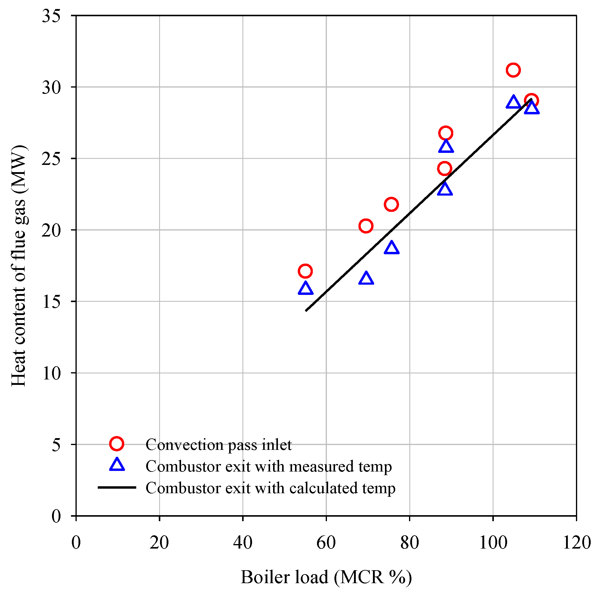
3.3. After-Combustion in Convection Pass

The superheater dries up and heats up the saturated steam coming out of the drum up to the designed temperature. The design purpose of the de-superheater is to consume excess heat, which is a deviation from the design margin in the convection pass, and to control the final steam temperature precisely. The combustor has only the evaporator wall, the convection pass consisting of S/H 2, S/H 1, and the economizer. If the after-combustion proceeds at the combustor exit, the flue gas would carry excess heat far more than the design; thus, a large number of de-superheaters is required between the S/H 1 and S/H 2 to remove this extra heat. The amount of spray water at the de-superheater added to the super heater, which increases the quantity of the final steam, is a quantitative indicator of after-combustion. With the same boiler heat capacity, the quantity of the combustor evaporation m w without after-combustion is decreased to m w with after-combustion.
If the measured temperature at the convection pass inlet temperature is reliable, the heat content when after-combustion occurred can be calculated with the measured temperature using Equation (3). The equations for the superheater section are as follows:
Q S H = m m i x · T r e f T c o n C p m i x d T
Q S H = m w H S H H s a t + m d e s H S H H w + m m i x · T r e f T E C O C p m i x d T
where Q S H is the heat input from the flue gas and fly ash mixture to the superheater, T c o n is the measured convection pass inlet temperature, H S H is the enthalpy of superheated steam, H w is the enthalpy of the boiler feed water, m w is the mass flow rate of the feed water with after-combustion, and m w = m w + m d e s , and m d e s is the spray water rate at the de-superheater.
Figure 5 presents the comparison of the flue gas heat content at the combustor exit and convection pass inlet. The amount of heat can be calculated with thermodynamic calculations from Equation (8) using the measured and calculated temperatures, respectively. If the heat calculated using convection pass inlet temperature represents the actual flue gas conditions, the heat introduced to the super heater should be proportional to the measured temperature. However, the measured temperature does not represent the flue gas temperature at the location because at the combustor exit, at the cyclone, and even at the inlet of the convection pass, the combustion is not homogeneous due to the after-combustion, and the thermocouple only represents the conditions where it is installed.
Figure 6 presents the comparison of the calculated and measured spray water flow rate at the de-super heater. The heat content difference of the flue gas (10) is the difference between the heat content of the flue gas calculated by the measured inlet temperature of SH 2 and theoretical temperature calculated by Equations (8) and (3).
Δ Q = m m i x · T r e f T c o n C p m i x d T m m i x · T r e f T c o m b C p m i x d T     m d e s H S H H w
While the calculated spray water at de-superheater proportionally increased with the heat content difference of the flue gas, the measured spray water flow rate had no correlation with it. This deviation explains the measured temperature at the super heater inlet, and the heat content calculated by this temperature did not represent reliable thermodynamic conditions of flue gas. The measured spray water flow rate, however, provided more credulous information on the flue gas conditions and the extent of after-combustion. The amount of spray water presents the content of the after-combustion as in the Equation (11).
Q S H = m w + m d e s H S H H s a t + m d e s H s a t H E C O + m d e s H E C 0 H w + m m i x · T r e f T E C O C p m i x d T
The heat load of the de-superheater can be divided into three parts: economizing, evaporation, and superheating. Since economizing and superheating should occur in the convection pass even without after-combustion, the amount of heat generated from after-combustion is close to the amount of heat of the evaporation portion of the spray water at the de-superheater ( m d e s H s a t H E C O ) .

3.4. Improvement of Boiler Performance

In order to control the after-combustion, a wing wall evaporator (45 m2) in the upper combustor and a second evaporator (15 m2) in the convection pass inlet are installed in addition to the original combustor wall evaporator (330 m2). A total of 14% of the evaporator area is increased, and 4% of the area of the second evaporator is added from the initial design to absorb extra heat generated by after-combustion. Considering the same heat transfer coefficient among the water wall, wing wall, and second evaporator, the heat absorption of all three evaporator surfaces should increase by 18% absorption capability after the installation. The quantity of the after-combustion heat was as much as the spray water evaporation, m d e s H s a t H E C O , which had to be recovered in the superheater instead of in the evaporator. Figure 7 presents the heat content of each boiler unit with different boiler loads. Table 4 summarizes the heat content of the flue gas out of the combustor section and the heat content of the de-superheater.
The evaporation portion of the de-superheater to evaporator heat content was 6.6~10% (1.5~1.9 MWth) in between 76 and 109% load before boiler modification. After the modification, it reduced to ~4% (~0.9 MWth) in between 76 and 82% load. By adding two sets of evaporators (the wing wall and the second evaporator), the heat recovery ratio in the evaporator was increased from 55~59% before the modification to 58% after the modification. The after-combustion still occurred even after the wing wall and the second evaporator installation, but the spray water heat extraction reduced from 3.2 to 1.4 MWth. Around 1.8 MWth of excess heat was extracted by the additional evaporator before the flue gas entered S/H 2 at 76% load. The heat extraction capability of the second evaporator measured by using the overall heat transfer coefficient of the water wall was 0.5 and 0.7 MWth at 82 and 76% load, respectively. The second evaporator could control the S/H 2 upstream temperature below 800 °C; thus, it was more effective to control the after-combustion. The installation of the larger wing wall was relatively ineffective since it could only extract the remaining evaporator portion of spray water of around 0.9 MWth at 76% load. Also, the ineffective wing wall was monitored. When the combustor exit temperature was lower than 800 °C, carbon monoxide emission increased.

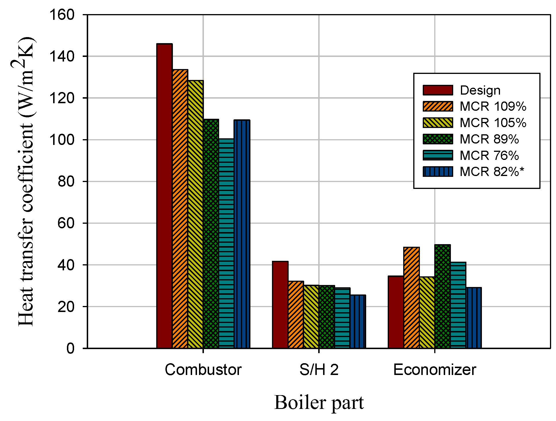
3.5. Heat Transfer Coefficient

The last boiler part in the 60 ton/h CFBC flue gas stream is the economizer, which recovers heat from low temperature flue gas and heats up feed water to a near boiling temperature. The temperature of the flue gas at the economizer inlet ( T E C O ) is calculated by the following equations.
Q E C O = m m i x · C p m i x T E C O T r e f
Q E C O = m w H E C O H w + m m i x · T r e f T A H C p m i x d T
where Q E C O is the heat input from flue gas to economizer and T E C O is the flue gas temperature at the economizer upstream.
Figure 8 is the comparison of the measured and calculated economizer inlet flue gas temperature according to the boiler load. Since the flue gas at the economizer inlet is more homogeneous, and no additional combustion occurs after S/H 1, the measured temperature is closer to the calculated value. The economizer inlet temperature is increased with the increasing boiler load due to the increasing heat requirement.
Figure 9 presents the measured heat transfer coefficient of the boiler units in the convection pass. The heat transfer in the convection pass is calculated as follows:
Q B = m w H E C O H w = h B   A B Δ T l
where Q B is the heat load of boiler unit in convection pass, h B is the overall heat transfer coefficient, A B is the heat transfer area, and Δ T l is the logarithmic mean temperature difference between the tube and the gas side inlet and outlet.
The heat transfer coefficient of S/H 2 had a lower value than that of the economizer. Since superheater tubes are likely to be contaminated by molten fly ash and sand particles at temperatures around 850 °C, the heat transfer was hindered by these hard deposits [28,29]. However, the economizer surface was exposed to a relatively low temperature of 500 °C where fly ash had already solidified. Consequently, the fly ash stuck less to the tube surface, and the tube surface was cleaner. The gas side heat transfer was less hindered than that of the super heater, and the overall heat transfer coefficient of the economizer will present that of the bare tube [30].

4. Conclusions

The operation data of a CFBC boiler, which was designed for waste-derived fuel combustion, with a capacity of a 60 ton/h steam rate was analyzed and conclusions were drawn as follows:
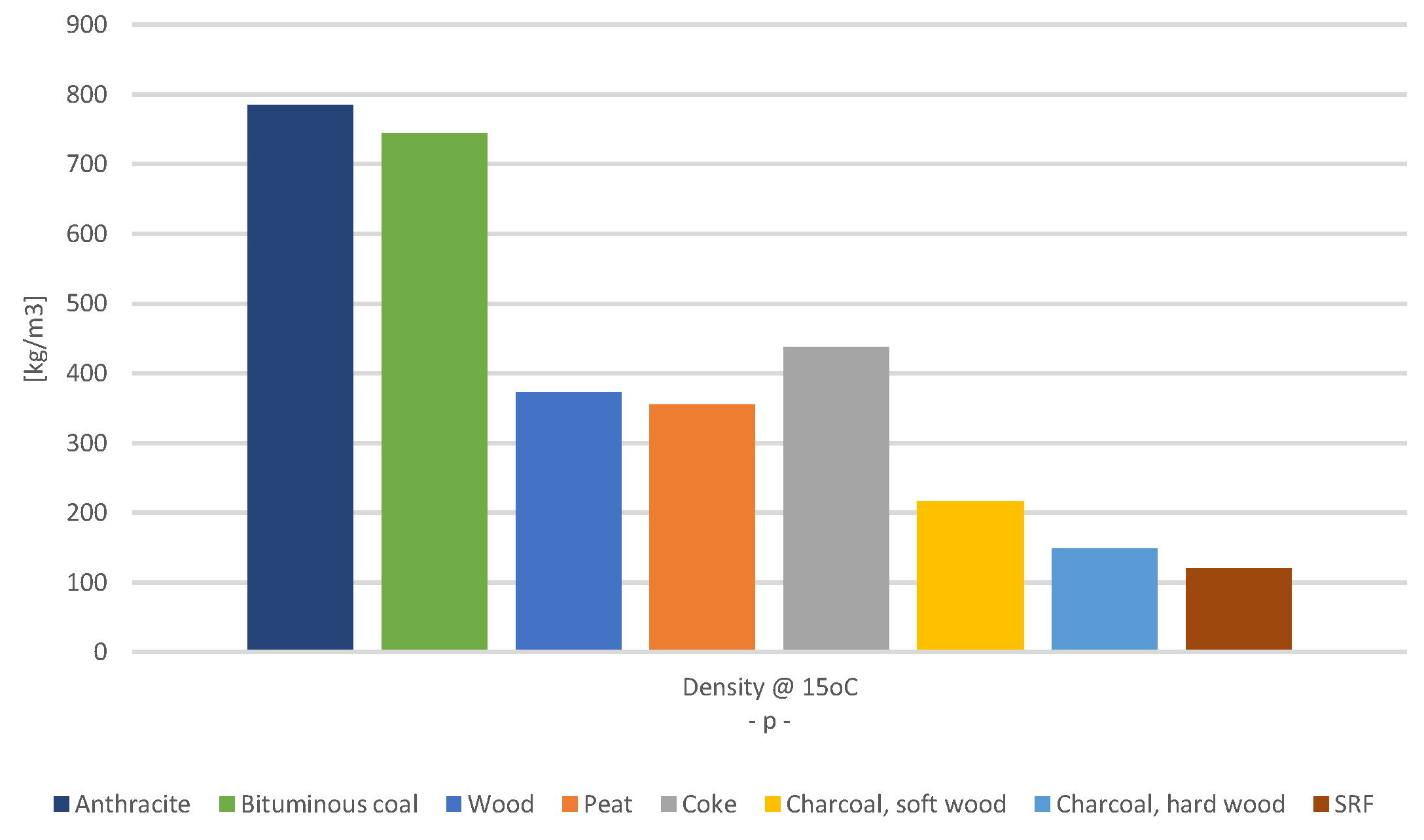
  • After-combustion occurred because of the light density of the fuel. The measured higher temperature at the combustor exit and the convection pass inlet could not represent its thermodynamic conditions due to non-homogeneous combustion characteristics. Thermodynamic calculation provided more consistent heat information on the variation of operation conditions. Inside of the convection pass, where combustion is completed and gas conditions are more homogeneous, the measured temperature and calculated temperature coincided well.
  • The load distribution of the de-superheater decreases from 1.76% to 0.87% in 89% MCR before installation of the evaporator and 82* % MCR load distribution of each boiler part after installation. The change of the heat transfer area according to the installation of the evaporator directly affects the amount of spray water in the de-superheater. Through this, the improvement of the heating area for the prevention of after-combustion through the quantitative analysis of spray water seems reasonable.
  • The installation of the additional heat transfer unit in the convection pass inlet (second evaporator) based on the spray water at the de-superheater amount and the heat balance calculation controlled the S/H 2 upstream temperature below 800 °C; thus, it was more effective to control after-combustion. The installation of the larger wingwall was relatively ineffective since it could only extract the remaining evaporator portion of spray water of around 0.9 MWth at 76% load.
  • This suggests that it is appropriate to establish an after-combustion and a heat transfer area caused by the physical characteristics of the SRF fuel used. In addition, the quantitative change of the spray water supplied from the de-superheater can be used as a major calculation data to calculate the heat transfer area according to the load of the boiler. In the power generation equipment of all fuels in which the after-combustion generated, the problem resolution is possible in all facilities in which the de-superheater is installed and operating in the same method.

Author Contributions

Data curation, Y.C. and D.-H.B.; Writing—original draft, J.-S.S.; Writing—review & editing, D.S. and C.-H.C. All authors have read and agreed to the published version of the manuscript.

Funding

This work was supported by the National Research Council of Science & Technology (NST) grant by the Korea government (MSIP) (No. CRC-15-07-KIER).

Institutional Review Board Statement

Not applicable.

Informed Consent Statement

Not applicable.

Data Availability Statement

Not applicable.

Conflicts of Interest

The authors declare no conflict of interest.

Nomenclature

A B heat transfer area[m2]
A E V A heat transfer area of evaporator[m]
C p ,   a i r heat capacity of air[kJ/(kmol   ·   K)]
C g heat capacity of gas[kJ/(kmol   ·   K)]
C p heat capacity of particle[kJ/(kmol   ·   K)]
C p m i x heat capacity of flue gas and fly ash mixture[kJ/(kmol   ·   K)]
d p diameter of particle inside combustor[m]
e b emissivity of combustor[-]
e s emissivity of surface of water wall tube[-]
g gravitational acceleration[m/s2]
H E C 0 enthalpy of feed water at economizer outlet[kJ/kg]
H S H enthalpy of superheated steam[kJ/kg]
H s a t enthalpy of saturated steam at drum pressure[kJ/kg]
H w enthalpy of boiler feed water[kJ/kg]
h c combustor overall heat transfer coefficient[W/(m2 · K)]
h c o n v convective heat transfer coefficient[W/(m2 · K)]
h d dispersed phase heat transfer coefficient[W/(m2 · K)]
h r radiative heat transfer coefficient[W/(m2 · K)]
K g thermal conductivity of gas[W/(m2 · K)]
m w mass flow rate of feed water with after-combustion[kg/s]
m d e s mass flow rate of spray water at de-superheater [kg/s]
m a i r mole flow rate of air[kg · mol/s]
m m i x mass flow rate of flue gas and fly ash mixture[kg/s]
m w mass flow rate of feed water[kg/s]
P r Prandtl number[-]
Q a i r heat input to the combustor by heated air through air heater[kW]
Q a i r , A heat gain of air through air heater[kW]
Q B heat load of boiler unit in convection pass[W]
Q B A heat loss by bottom ash discharge[kW]
Q E C O heat input from flue gas to economizer[kW]
Q E V A evaporator heat load[W]
Q f u e l heat input to the combustor by fuel combustion[kW]
Q f l u e , A heat input from flue gas and fly ash mixture to super heater[kW]
Q S H heat input from flue gas and fly ash mixture to super heater[kW]
T b temperature of combustor[K]
T c o m b temperature of flue gas at combustor exit or super heater upstream[K]
T E C O flue gas temperature at economizer upstream[K]
T i n ,   a i r inlet temperature at air heater[K]
T o u t ,   a i r outlet temperature at air heater[K]
T r e f reference temperature[K]
T w temperature of water wall tube[K]
T c o n measured convection pas inlet temperature[K]
h E V A overall heat transfer coefficient of evaporator[W/(m2 · K)]
h B overall heat transfer coefficient[W/(m2 · K)]
u t terminal velocity of particle[m/s]
ρ d i s density of particle[kg/m3]
ρ p density of particle[kg/m3]
σ Stefan-Boltzman constant, 5.67 × 10⁻⁸[W/(m2 · K4)]
Δ T l logarithmic mean temperature difference between the tube and the gas side inlet and outlet  [K]

References

  1. Ferrer, E.; Aho, M.; Silvennoinen, J.; Nurminen, R.-V. Fluidized bed combustion of refuse-derived fuel in presence of protective coal ash. Fuel Process. Technol. 2005, 87, 33–44. [Google Scholar] [CrossRef]
  2. Narukawa, K.; Goto, H.; Chen, Y.; Yamazaki, R.; Moi, S.; Fujima, Y.; Hirama, T.; Hosoda, H. Japanese RDF-Fired Power Generation System and Fundamental Research on RDF Combustion; American Society of Mechanical Engineers: New York, NY, USA, 1997. [Google Scholar]
  3. Ryu, C.; Shin, D. Combined heat and power from municipal solid waste: Current status and issues in South Korea. Energies 2012, 6, 45–57. [Google Scholar] [CrossRef] [Green Version]
  4. Korea Ministry of Environment. Amendment of the Enforcement Decree of the Waste Control Act, ME Decree; Korea Ministry of Environment: Sejong City, Korea, 2007.
  5. Korea Ministry of Environment. Amendment of the Enforcement Decree of the Clean Air Conservation Act, ME Act; Korea Ministry of Environment: Sejong City, Korea, 2007.
  6. Basu, P. Combustion of coal in circulating fluidized-bed boilers: A review. Chem. Eng. Sci. 1999, 54, 5547–5557. [Google Scholar] [CrossRef]
  7. Dong, H.; Jiang, X.; Lv, G.; Chi, Y.; Yan, J. Co-combustion of tannery sludge in a commercial circulating fluidized bed boiler. Waste Manag. 2015, 46, 227–233. [Google Scholar] [CrossRef]
  8. Okasha, F.; Zaater, G.; El-Emam, S.; Awad, M.; Zeidan, E. Co-combustion of biomass and gaseous fuel in a novel configuration of fluidized bed: Thermal characteristics. Energy Convers. Manag. 2014, 84, 488–496. [Google Scholar] [CrossRef]
  9. Shun, D.; Bae, D.-H.; Park, J.; Lee, S.-Y. Development of commercial CFBC boiler for refuse derived fuel. In Proceedings of the 27th Annual International Pittsburgh Coal Conference, Istanbul, Turkey, 11–14 October 2010; p. 2174. [Google Scholar]
  10. Shun, D.; Bae, D.-H.; Jo, S.-H.; Lee, S.-Y. Combustion Study of 1MWe Circulating Fluidized Boiler for RDF. Korean Chem. Eng. Res. 2012, 50, 837–842. [Google Scholar] [CrossRef]
  11. Shun, D.; Bae, D.-H.; Jo, S.-H.; Lee, S.-Y. Design of commercial scale of CFBC boiler for waste and biomass. In Proceedings of the International Conference on Advanced Technology & Sustainable Development, Ho Chi Minh City, Vietnam, 27–28 November 2016; p. 436. [Google Scholar]
  12. Ściubidlo, A.; Majchrzak-Kucęba, I.; Niedzielska, M. Comparison of fly ash from co-combustion of coal/solid recovered fuel (SRF) and coal/refuse derived fuel (RDF). J. Phys. Conf. Ser. 2019, 1398, 012015. [Google Scholar] [CrossRef]
  13. Wanchan, W.; Khongprom, P.; Limtrakul, S. Study of wall-to-bed heat transfer in circulating fluidized bed riser based on CFD simulation. Chem. Eng. Res. Des. 2020, 156, 442–455. [Google Scholar] [CrossRef]
  14. Abdelmotalib, H.M.; Youssef, M.A.; Hassan, A.A.; Youn, S.B.; Im, I.-T. Heat transfer process in gas–solid fluidized bed combustors: A review. Int. J. Heat Mass Transf. 2015, 89, 567–575. [Google Scholar] [CrossRef]
  15. Basu, P.; Nag, P.K. Heat transfer to walls of a circulating fluidized-bed furnace. Chem. Eng. Sci. 1996, 51, 1–26. [Google Scholar] [CrossRef]
  16. Kawahara, Y. Application of high temperature corrosion-resistant materials and coatings under severe corrosive environment in waste-to-energy boilers. J. Therm. Spray Technol. 2007, 16, 202–213. [Google Scholar] [CrossRef]
  17. Daouk, E.; Sani, R.; Minh, D.P.; Nzihou, A. Thermo-conversion of Solid Recovered Fuels under inert and oxidative atmospheres: Gas composition and chlorine distribution. Fuel 2018, 225, 54–61. [Google Scholar] [CrossRef] [Green Version]
  18. Varol, M.; Symonds, R.; Anthony, E.J.; Lu, D.; Jia, L.; Tan, Y. Emissions from co-firing lignite and biomass in an oxy-fired CFBC. Fuel Process. Technol. 2018, 173, 126–133. [Google Scholar] [CrossRef] [Green Version]
  19. Madanayake, B.N.; Gan, S.; Eastwick, C.; Ng, H.K. Biomass as an energy source in coal co-firing and its feasibility enhancement via pre-treatment techniques. Fuel Process. Technol. 2017, 159, 287–305. [Google Scholar] [CrossRef]
  20. Hernandez-Atonal, F.D.; Ryu, C.; Sharifi, V.N.; Swithenbank, J. Combustion of refuse-derived fuel in a fluidized bed. Chem. Eng. Sci. 2007, 62, 627–635. [Google Scholar] [CrossRef]
  21. Omer, A.; Weng, M. Effect of primary air maldistribution due to nozzle wear on CFBC performance. Fuel Process. Technol. 2018, 173, 191–196. [Google Scholar] [CrossRef]
  22. Lee, S.H.; Themelis, N.J.; Castaidi, M.J. High-temperature corrosion in waste-to-energy boilers. J. Therm. Spray Technol. 2007, 16, 104–110. [Google Scholar] [CrossRef] [Green Version]
  23. Sorell, G. The role of chlorine in high temperature corrosion in waste-to-energy plants. Mater. High Temp. 1997, 14, 207–220. [Google Scholar] [CrossRef]
  24. Park, J.H.; Lee, D.-H.; Han, K.-H.; Shin, J.-S.; Bae, D.-H.; Shim, T.-E.; Lee, J.H.; Shun, D. Effect of chemical additives on hard deposit formation and ash composition in a commercial circulating fluidized bed boiler firing Korean solid recycled fuel. Fuel 2019, 236, 792–802. [Google Scholar] [CrossRef]
  25. Basu, P. Circulating Fluidized Bed Boilers: Design, Operation and Maintenance; Elsevier: Amsterdam, The Netherlands, 2015. [Google Scholar]
  26. Basu, P. Combustion and Gasification in Fluidized Beds; CRC Press: Boca Raton, FL, USA, 2006. [Google Scholar]
  27. Wen, C.-Y.; Miller, E. Heat transfer in solids-gas transport lines. Ind. Eng. Chem. 1961, 53, 51–53. [Google Scholar] [CrossRef]
  28. Singh, S. Pre-determination of the Fouling and Cleanliness Factor of the Heat Exchanger. Int. J. Eng. Res. Appl. 2012, 2, 1177–1179. [Google Scholar]
  29. Zbogar, A.; Frandsen, F.J.; Jensen, P.A.; Glarborg, P. Heat transfer in ash deposits: A modelling tool-box. Prog. Energy Combust. Sci. 2005, 31, 371–421. [Google Scholar] [CrossRef]
  30. Walter, A.; Hofmann, R. How can the heat transfer correlations for finned-tubes influence the numerical simulation of the dynamic behavior of a heat recovery steam generator. Appl. Therm. Eng. 2011, 31, 405–417. [Google Scholar] [CrossRef] [Green Version]
Figure 1. Density of soild fuels.
Energies 15 05507 g001
Figure 2. Process diagram of 60 ton/h CFBC boiler. (1) Fuel surge bin, (2) Drum, (3) Combustor, (4) Cyclone, (5) S/H(superheater) 2, (6) de-superheater, (7) S/H(superheater) 1, (8) Economizer, (9) Air pre-heater, (10) P.A. Fan, (11) SDR (Semi-Dry Reactor; HCl and SOx absorption), (12) Bag filter 1, (13) Bag filter 2, (14) I.D. Fan.
Energies 15 05507 g002
Figure 3. Measured and calculated temperature difference at boiler locations.
Energies 15 05507 g003
Figure 4. Effect of the economizer downstream temperature on the air temperature at the air heater exit and the flue gas temperature at the combustor exit.
Energies 15 05507 g004
Figure 5. Flue gas heat content at the combustor exit and convection pass inlet based on both the measured and calculated temperatures.
Energies 15 05507 g005
Figure 6. A comparison of the calculated spray water flow rate by convection pass inlet temperature and measured flow rate of spray water at de-superheater.
Energies 15 05507 g006
Figure 7. Relative boiler partition by boiler load (* After additional evaporator installation).
Energies 15 05507 g007
Figure 8. Measured and calculated flue gas temperature at the economizer inlet.
Energies 15 05507 g008
Figure 9. Heat transfer coefficient of boiler parts. (* After additional evaporator installation).
Energies 15 05507 g009
Table 1. Design specifications.
SpecificationsUnitValue
Net electricity outputMWe5.5–14.5
Maximum steam rateton/h60
Final steam temperature°C450
Final steam pressureAta45
Feed water temperature°C143
Boiler load variation% MCR55–109
Fuel flow rangeton/h5.4–10.6
Table 2. Properties of the design and test fuels.
ParameterDesign FuelTest Fuel LowTest Fuel High
Carbon, wt%43.541.444.6
Hydrogen, wt%5.85.86.3
Nitrogen, wt%0.71.01.0
Sulfur, wt%0.20.20.2
Oxygen, wt%24.221.324.2
Chloride, wt%1.41.01.1
Water, wt%7.012.48.9
Ash, wt%17.216.913.7
Bulk density, kg/m3700400400
High Heating Value, analysis, kJ/kg18,74418,99020,781
Table 3. Operation data of 60 ton/h CFBC combustion.
% Load10910588765582 *76 *
Steam rate (kg/h)65,60062,90053,00045,40033,00048,00045,600
Measured combustor exit temperature (°C)905913894831760785800
Calculated combustor exit temperature (°C)882889864861668816801
Convection pass inlet temperature (°C)921978947953815894881
2nd evaporator down temperature (°C)-----805757
Heat transfer coefficient of wall, measured (W/m2-K)1341281101008910999
Radiative heat transfer coefficient, calculated (W/m2-K)12913112511195101104
Convective heat transfer coefficient, calculated (W/m2-K)37373735343434
Average density in freeboard (kg/m3)33.424.28.610.44.67.86.4
SO2 emission (ppm)1.62.01.32.83.40.10.1
NOx emission (ppm)35.434.442.20.81.643.535.7
O2 (%)4.65.54.75.39.17.47.7
HCl (ppm)6.67.76.79.618.93.55.0
(* After additional evaporator installation).
Table 4. Heat content of flue gas and boiler units according to boiler location (using measured temperature).
Heat Content [MW]\% Load10910588765582 *76 *
Total boiler output49.847.840.434.724.937.334.7
Evaporator28.327.623.019.014.721.520.2
Flue gas at combustor exit28.428.822.718.716.522.621.5
Flue gas at 2nd evaporator down-----26.223.9
Flue gas at convection pass inlet29.031.224.321.817.123.320.2
Spray water heat rate2.72.62.53.21.01.61.4
Spray water evaporation portion1.61.61.51.90.60.90.9
(* After additional evaporator installation).
Publisher’s Note: MDPI stays neutral with regard to jurisdictional claims in published maps and institutional affiliations.

