Article

Kinematic and Dynamic Simulation Analysis of Modified Conventional Beam Pumping Unit

1
Mechanical Science and Engineering Institute, Northeast Petroleum University, Daqing 163318, China
2
School of Petroleum Engineering, Northeast Petroleum University, Daqing 163318, China
3
Oil Production Engineering Research Institute, Daqing Oilfield Co., Ltd., Daqing 163453, China
*
Author to whom correspondence should be addressed.
Energies 2022, 15(15), 5496; https://doi.org/10.3390/en15155496
Submission received: 8 May 2022 / Revised: 23 July 2022 / Accepted: 27 July 2022 / Published: 29 July 2022
(This article belongs to the Special Issue Advances in Petroleum Exploration and Production)

Abstract

:
The large net torque fluctuations in the reducer output shafts of conventional beam pumping units and the existence of negative torque are the decisive factors that lead to their low efficiency and high energy consumption. This study developed a positive torque modulation scheme for conventional beam pumping units, which was based on the principle of the follow-up secondary balance of the connecting rod. The CYJ10-4.2-53HF conventional beam pumping unit was selected as the research object. The kinematic and dynamic simulation analysis of the modified pumping unit was carried out using ADAMS software. The results showed that secondary balance torque curves could realize the function of “peak cutting and valley filling” for the curves after the primary balance and that the modified pumping unit could achieve a full-cycle positive value for the reducer output shaft and verify the feasibility of our modulation scheme. A secondary balance offset angle of 315° was the best choice as the amplitude of the torque curve clearly increased and the phase remained basically the same when the radius of the mass center of the secondary balance increased. Therefore, when the offset angle value of the secondary balance weight was determined, the radius of the mass center could be changed by adjusting the position of the secondary balance weight to achieve the balance adjustment.

1. Introduction

At present, oil production using sucker rod pumps is the main and most widespread method for the operation of oil wells [1,2]. Currently, various sucker rod pumping units are applied in the operation of oil wells. Among of the existing mechanical methods oil production, the most common is the use of beam pumping units [2,3,4]. Beam pumping units have a history of more than 150 years of application in over 900,000 oil wells worldwide. Beam pumping units have the advantages of simple structures, reliability and durability [5] and are still one of the main oil recovery methods for oil production in oil fields. There are more than 200,000 oil wells in China, with beam pumping units employed in 80% of them [6,7].
However, the torque in reducer output shafts is superposed on the polished rod torque and the counterweight torque [8]. Since polished rod loads vary greatly in up-down strokes and act on reducer output shafts through a four-link mechanism, they lead to the inherent fluctuation characteristics of polished rod torque, which varies greatly in up-down strokes and is mainly positive during the up stroke and negative during the down stroke [4,9,10]. Counterweight torque is a standard cosine curve, so counterweight torque is difficult to balance effectively with polished rod torque for full cycles and reducer output shaft torque fluctuates greatly and causes negative torque in beam pumping units. Reducer output shaft torque is transmitted by motors through V-belts and gearboxes to ensure the normal operation of pumping units, so the fluctuation characteristics of reducer output shaft torque directly determine the installed power of motors and the efficiency of the systems [9,11]. Large fluctuations and high peaks in reducer output shaft torque result in high installed power and low system efficiency. Negative torque causes motor power generation, the reverse impact of gears, reductions in the life cycles of motors and gearboxes and the formation of inefficient areas in motors, so effectively balancing and reducing reducer output shaft torque and eliminating negative torque is key to energy saving in beam pumping units.
To solve these problems, many scholars and pumping unit manufacturing companies have developed a variety of new energy-saving pumping units [12,13,14,15,16,17,18]. Although these possess certain energy-saving effects, most of the new pumping units still do not solve the problem of negative torque in the reducer output shaft and have the disadvantages of poor reliability and difficult maintenance, which has restricted their development. On the other hand, beam pumping units account for more than 80% of the total number of pumping units, so it would be impossible to replace them all in a short time due to resource utilization and economic costs. Therefore, reasonable schemes need to be developed to carry out the low-cost transformation of conventional beam pumping units and modulate negative torque in the reducer output shaft into positive torque [19].
In this study, the CYJ10-4.2-53HF conventional beam pumping unit was chosen as the research object and a positive torque modulation scheme was developed, which was based on the fixed-axis secondary balance principle. The energy-saving mechanism of the modified beam pumping unit was verified via kinematic and dynamic analysis using ADAMS. The laws of the key parameters that affect the impact of secondary balance on torque curves was simulated and the key parameters were optimized.

2. Modulation Principle and Method

2.1. Modulation Principle

Based on the principle of fixed-axis secondary balance [20], torque modulation was carried out for the CYJ10-4.2-53HF conventional beam pumping unit. As shown in Figure 1, after the primary balance, negative torque appeared near 0° and 180° and peaks appeared near 90° and 270°. Within a pumping cycle, the torque presented two peaks and two valleys after the primary balance. According to the net torque characteristics after the primary balance, a secondary balance device was installed in the pumping unit. The secondary balance rotation speed was twice that of the primary balance, which was achieved using a secondary speed increasing mechanism. Within a pumping cycle, the torque that was formed by the secondary balance in the reducer output shaft had two peaks and two valleys and the peaks of the secondary balance torque corresponded to the valleys of the torque after the primary balance and vice versa. After superposition, the original negative torque became positive, the peak values became smaller and the whole torque curve became gentler. The installed power of the pumping unit motor after the secondary balance was remarkably smaller and the energy-saving effects were obvious [19].

2.2. Modulation Method

The positive torque modulation method and the structure of conventional beam pumping units that are based on the principle of fixed-axis secondary balance are shown in Figure 2 and Figure 3, respectively. The modified pumping unit included secondary balance system on the basis of the original balance system. The secondary balance system mainly included a speed increasing gearbox and a secondary counterweight. The original connecting rod was replaced by a connecting rod frame, which connected the beam to the speed increasing gearbox. The input shaft of the speed increasing gearbox was equipped with a large gear and the output shaft was equipped with a small gear. The transmission ratio of the large gear to the small gear was 1:2. The input shaft of the speed increasing gearbox was fixed with a large crank and the output shaft was connected to the secondary counterweight [19].

2.3. Working Process and Balance Analysis

When the pumping unit was working, the motion of the original connecting rod was replaced by the speed increasing gearbox and the connecting rod frame because they were fixed together. The secondary counterweight was fixed to the output shaft of the speed increasing gearbox, so the secondary counterweight not only followed the spatial plane movement of the speed increasing gearbox and the connecting rod frame, but also rotated around the output shaft of the speed increasing gearbox. Therefore, this positive torque modulation method could be called a follow-up secondary balance of the connecting rod. The gravity and inertia forces of the secondary counterweight added a dynamic counterweight to the primary balance crank to play the role of primary balance. Therefore, it could be seen that the secondary balance that was based on the follow-up of the connecting rod not only played the role of secondary balance, but also the role of primary balance, which was conducive to reducing the weight of the primary balance and saving steel [19].

3. Simulation Modeling

The influence of the quality parameters and structural parameters of each part of the pumping unit on the dynamic properties of the transformed beam pumping unit was fully considered. Firstly, the modified CYJ10-4.2-53HF pumping unit simulation prototype was established using SolidWorks; then, the model was imported into ADAMS software to calculate and systematically analyze the time response laws of the key parameters that affected secondary balance.

3.1. Conditional Assumptions

When using ADAMS software for analysis, the following assumptions could be made, according to the actual structural and bearing characteristics of the pumping unit and considering the main factors that affected the mechanical properties of the pumping unit [21]:
(1)
The influence of the micro-stress deformation of each component was neglected and the unit was regarded as a purely rigid body;
(2)
The rotating bearing was simplified to be treated by the rotating pair in ADAMS and the friction between the bearing and the shaft and the dissipation of the friction energy were ignored;
(3)
The gear transmission was simplified to be treated by the gear pair in ADAMS and the energy dissipation during the gear transmission process was ignored;
(4)
The shapes of the fixed parts (such as the base, beam support, reducer base and reducer shell), were simplified as they had no impact on the dynamic performance of the pumping unit;
(5)
The influence of the motor load on speed change was ignored and the crank of the pumping unit was regarded as having a uniform angular speed rotation.

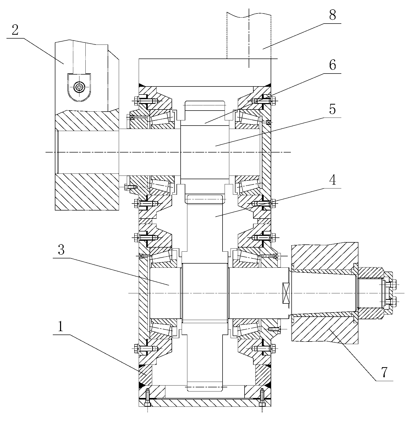
3.2. Virtual Prototype

According to the basic dimensions of each moving part of the CYJ10-4.2-53HF pumping unit, as shown in Table 1, the full-scale model that was built in SolidWorks is shown in Figure 4. The model was then saved in Parasolid format and imported into ADAMS.

3.3. Properties of the Modified Parts

Modifying the attributes of each part mainly included editing the part names and qualities in ADAMS. The model qualities were mainly based on the actual quality settings of the CYJ10-4.2-53HF pumping unit. The qualities of the main components that affected the mechanical properties of the modified pumping unit are listed in Table 2.

3.4. Constraints

The constraints were realized by applying various kinematic pairs. The constraints between the various parts of the modified beam pumping unit mainly involved fixed pairs, rotating pairs, gear pairs and driving constraints. The specific settings are listed in Table 3.

3.5. Boundary Conditions

The rotation drive constraint was applied to the output shaft of the reducer so that the crank rotated at a uniform speed. The stroke frequency of the pumping unit was set at 6 times/min, i.e., the rotation angular speed of the rotation drive constraint was 36°/s and the time that was required for a full pumping cycle was 10 s. The gravity, inertia and vibration forces and other factors that affected the suspension point load of the pumping unit were fully considered. The suspension point load variation curve of real conditions in a pumping cycle was applied to the simulated suspension point, as shown in Figure 5.

4. Analysis of Simulation Results

In order to ensure the accuracy of our simulation results, the number of simulation steps was set to 500. The time history change curves of various required parameters were extracted in the postprocessing of the simulations and the simulation results were analyzed. The virtual simulation model in ADAMS is shown in Figure 6.

4.1. Kinematic Simulation

Figure 7 shows the displacement, velocity and acceleration curves of the suspension point of the beam pumping unit. As can be seen from Figure 8, the rotation process of the small crank was non-uniform in angular velocity as the maximum absolute value of the angular velocity was at the bottom of dead center and the average value of the angular velocity was −72°/s, which was twice the angular velocity of the large crank. This was to ensure the periodicity and the repeatable superposition of the motion.
As can be seen from Figure 9, the angular velocity of the beam was negative most of the time and was only positive for a fraction of the time because the crank rotation angle of the up stroke was more than 180° and the crank rotation angle of the down stroke was less than 180°. The maximum angular velocity of the up and down strokes was nearly 1/2 of a stroke of the suspension point, while the maximum angular acceleration was near the upper and lower boundaries of dead center.

4.2. Dynamic Simulation

4.2.1. Analysis of the Torque Superposition Process

Ignoring the influence of the motion inertia of the four-bar linkage, only the crank torque curve that was applied by the suspension point load was considered. The primary balance and secondary balance masses were set to zero and the suspension point load was applied according to the load curve that was shown in Figure 5. After the simulations, the torque curve of the reducer output shaft was obtained, as shown in Figure 10. Due to the structure of the four-bar linkage, the action time of the up stroke was more than 5 s under the action of the suspension point load (which was more than 180°) while the action time ofn the down stroke was less than 5 s (which was less than 180°).
The suspension point load, secondary balance weight and four-bar linkage weight were all set to zero to consider the reducer output shaft torque curve that was formed under the action of the primary balance alone. The reducer output shaft torque curve after simulation is shown in Figure 11. As can be seen from Figure 11, the torque curve followed an approximate sinusoidal variation law under the action of the primary balance, which was negative during the up stroke and positive during the down stroke.
The secondary balance mass was set to zero so as to only consider the reducer output shaft curve that was formed under the action of the suspension point load and the primary balance. As can be seen from the curve in Figure 12, there was still negative torque at the upper and lower boundaries of dead center after the primary balance.
As can be seen from Figure 13, the torque variation law that affected the large gear and the pinion was completely consistent and was similar to the sinusoidal law. There were two peaks and valleys, which were formed in a cycle. Because the reference diameter of the large gear was twice that of the pinion, the torque amplitude of the large gear was also twice that of the pinion and the curve was completely symmetrical along the abscissa at 4.5 s.
As can be seen from Figure 14, the torque of the secondary balance weight that acted on the output shaft of the reducer was very different from that of the large gear shaft of the speed increasing gearbox. The torque amplitude of the reducer output shaft was greater than that of the large gear shaft because the torque in the large gear shaft was only from the rotation of the secondary balance weight, while the torque in the reducer output shaft was superposed by two parts: the rotation of the secondary balance weight and the primary balance, which was generated by its own weight and motion inertia force along with the spatial plane motion of the connecting rod. It could also be concluded that the secondary balance weight not only played the role of secondary balance in the positive torque modulation scheme of the follow-up secondary balance of the connecting rod, but also that of the primary balance. Compared to fixed-axis secondary balance, this positive torque modulation scheme was conducive to reducing the mass of the primary balance weight and saving steel.
The torque superposition process in the output shaft of the reducer is shown in Figure 15. The torque from the output shaft of the reducer still had negative torque after the primary balance; however, the net torque completely changed to a positive value after the secondary balance and the peak torque decreased. The torque superposition process achieved the effect of “peak cutting and valley filling” for the original torque curve, which once again verified the feasibility of this positive torque modulation scheme.

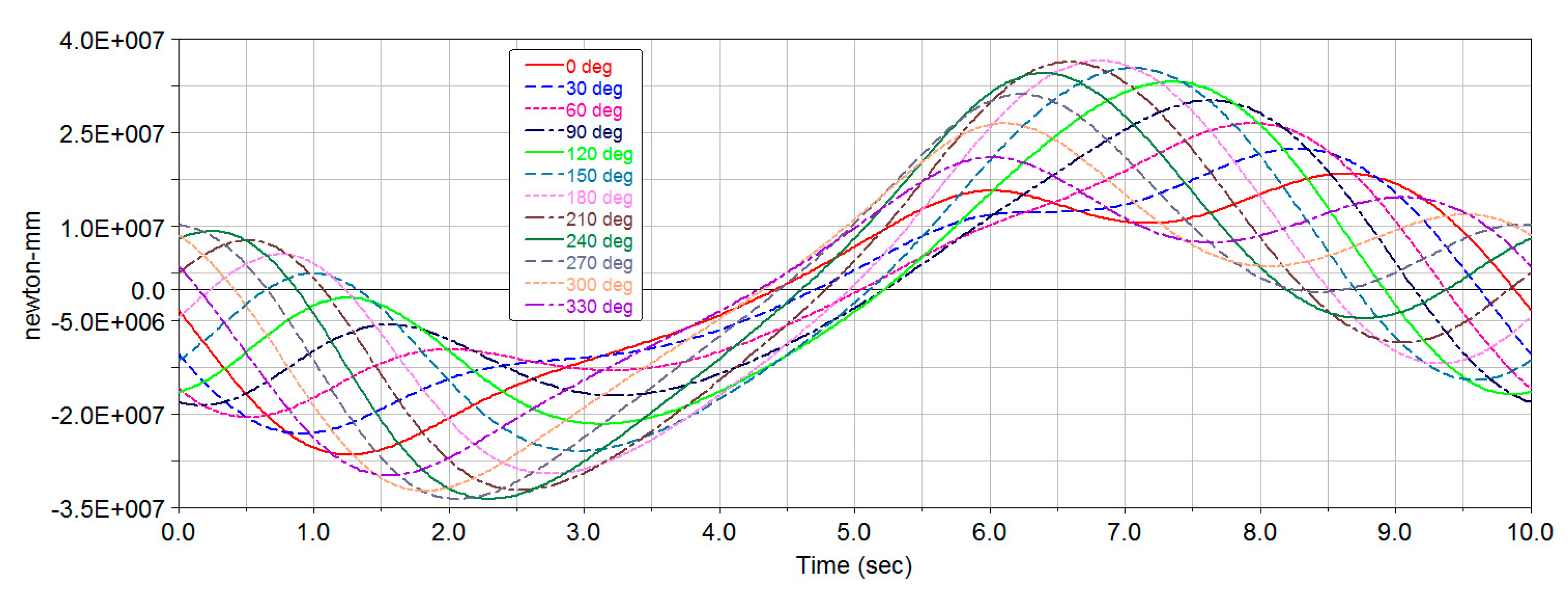
4.2.2. Influencing Factor Analysis of the Secondary Balance

At the initial moment, the coordinates of the rotation axis of the secondary crank were (−119.6559262832, 3363.7915871441, −1771.9753325099), the distance between the mass center of the secondary crank and the rotation axis was 377.55 mm and the coordinates of the mass center of the secondary balance at 12 o’clock were (−119.6559262832, 4012.3454134886, −1771.9753325099). According to the coordinate transformation law:
x = x 1 y = y 1 + a cos θ z = z 1 a sin θ
where:
  • x, y, z are the mass center coordinates of the secondary balance crank after rotation (mm);
  • x1, y1, z1 are the coordinates of the center of the secondary balance rotation (mm);
  • θ is the rotation angle of the crank centroid (°);
  • a is the radius of the crank centroid (mm).
We rotated the secondary crank counterclockwise by 30°, 60°, 90°, 180°, 210°, 240°, 270°, 300°, 330° and 360° to obtain the mass center coordinates of the secondary balance crank, as shown in Table 4.
We set the suspension point load and the mass of the primary balance weight to zero and the secondary balance mass to 1200 kg. Therefore, the output shaft torque of the reducer was only caused by the secondary balance weight. Figure 16 shows the output shaft torque curves of the reducer with different secondary balance offset angles. As can be seen from Figure 16, the use of different offset angles had a great impact on the fluctuation forms of the torque curves, which not only caused changes in the curve phases, but also led to differences in the curve amplitudes. The curves that were composed of two peaks and valleys were basically negative during the up stroke and positive during the down stroke. The minimum and maximum values of the curves were generated near the middle of the up and down strokes, respectively. According to the characteristics of the torque curve of the reducer output shaft after the primary balance, the offset angle that corresponded to a curve with a positive value at the beginning and end of the crank rotation cycle was selected as the reference value for the reasonable offset angle of the secondary balance. Three curves with offset angles of 270°, 300° and 315° were then selected as the secondary balance torque curves.
Only the torque curve of the reducer output shaft under the influence of the secondary balance was considered. We set the suspension point load and the mass of the primary balance weight to zero to change the mass of the secondary balance. The torque curve of the reducer output shaft is shown in Figure 17. As can be seen from Figure 17, the changes in the secondary balance mass only changed the torque amplitude and had no effect on the phase.
The variation law of the reducer output shaft torque under the action of the secondary balance weight, which was influenced by different stroke frequencies, is shown in Figure 18. The stroke frequencies that were applied to the virtual prototype were 6 times/min, 8 times/min and 10 times/min. As can be seen from Figure 18, the variation law of the reducer output shaft torque curve under the different stroke frequencies was basically unchanged. As the stroke frequency increased, the amplitude increased and the minimum value decreased slowly, while the maximum value increased significantly and the positive torque value at the bottom of dead center decreased when the abscissa was zero. Therefore, it could be concluded that the greater the stroke frequency, the more unfavorable the secondary balance effect.
The initial centroid coordinates of the secondary balance when the offset angle was 300° and the centroid radius was 377.55 mm, 500 mm and 750 mm are shown in Table 5.
The torque curves of the reducer output shaft with an offset angle of 300° and different centroid radii of the secondary balance crank are shown in Figure 19. When the radius of the center of the mass increased, the amplitude of the torque curve increased obviously and the change in centroid radius had little effect on the phase of the curve. Therefore, when the offset angle value of the secondary balance weight was determined, the centroid radius could be changed by adjusting the position of the secondary balance weight to achieve balance adjustment.

4.2.3. Determination of a Reasonable Offset Angle

Among the factors that affected the secondary balance, the torque curve of the secondary balance that acted on the reducer output shaft had to be determined once the offset angle of the secondary balance was determined. The mass and centroid radius of the secondary balance could be ignored because they only affected the amplitude of the secondary balance and had little influence on the phase of the secondary balance that acted on the torque of the reducer output shaft. The torque amplitude that was required by the secondary balance was related to the suspension point load of the actual pumping unit. Therefore, only the offset angle of the secondary balance, which was independent from the actual conditions, was determined here.
The applied suspension point load was consistent with the above suspension point load. We set the mass of the primary balance crank and the balance weight as shown in Table 2. We set the total mass of the secondary balance crank and the balance weight as 1200 kg and we set the secondary balance offset angle as 285°, 300°, 315° and 330° for the simulation tests. The secondary balance centroid coordinates when the offset angle was 300° and 330° are shown in Table 5. The centroid coordinates when the offset angle was 285° and 315° were, respectively:
  • (−119.6559262832, 3731.5087176225, −1407.2900367944)
  • (−119.6559262832, 3900.7597523817, −1505.0071672729)
The torque curves of the reducer output shaft for the different secondary balance offset angles are shown in Figure 20. The curves were prone to have negative values near the bottom of dead center and the abscissa at 3 s corresponded to a rotation angle of 108°. As can be seen from Table 6, the torque values were all positive when the secondary balance offset angle was 300° or 315° and were all negative values when the offset angle was 285° or 330°. Because the minimum value of the torque at 315° was greater than that at 300° while the maximum value, average value and root mean square value at 315° were less than those at 300°, the secondary balance offset angle of 315° was the best choice.

5. Conclusions

Based on the principle of secondary balance, a basic scheme for the positive torque modulation of a conventional beam pumping unit with the follow-up secondary balance of the connecting rod was developed. A modified mechanical structure for the connecting rod and a speed increasing gearbox were designed. The modified pumping unit could realize full-cycle positive torque, reduce the installed power and produce good energy-saving effects. It provided a feasible solution to the need for energy-saving traditional beam pumping units. This study analyzed the kinematics and dynamics of the modified pumping unit and the influence of key parameter laws on the effects of secondary balance using ADAMS, which revealed the mechanisms of the positive torque modulation. Our main conclusions were as follows:
(1)
The small crank rotated with a non-uniform angular velocity, but its average angular velocity was approximately twice that of the large crank so as to ensure the repeatability and superposition of the motion cycle;
(2)
Secondary balance not only played the role of secondary balance in balancing negative torque, but also the role of the primary balance. Different secondary balance offset angles not only caused changes in the curve phase, but also led to changes in the curve amplitude. The best choice for the secondary balance offset angle was 315°. The secondary balance torque curve could realize the “peak cutting and valley filling” for the curve after the primary balance, which achieved full-cycle positive values for the reducer output shaft net torque and verified the feasibility of this modulation scheme;
(3)
When the radius of the secondary balance mass center increased, the amplitude of the torque curve increased obviously and the phase remained basically the same. Therefore, when the offset angle of the secondary balance weight was determined, the radius of the mass center could be changed by adjusting the position of the secondary balance weight to achieve balance adjustment.

Author Contributions

Conceptualization, J.X.; methodology, J.X.; software, J.X.; validation, J.X., S.M. and W.L.; formal analysis, J.X.; investigation, J.X. and S.M.; resources, J.X.; data curation, J.X.; writing—original draft preparation, J.X.; writing—review and editing, J.X. and S.M.; visualization, J.X.; supervision, W.L.; project administration, J.X.; funding acquisition, J.X. All authors have read and agreed to the published version of the manuscript.

Funding

This research was funded by the Northeastern Petroleum University Youth Fund (grant number: xm122135), the Northeastern Petroleum University Research Start-up Fund (grant number: rc201733) and the Northeast Petroleum University Guided Innovation Fund from the Heilongjiang Provincial University Basic Research Business Fund (grant number: 2020YDL-08).

Data Availability Statement

Not applicable.

Conflicts of Interest

The authors declare no conflict of interest.

References

  1. Han, Y.; Li, K.; Ge, F.W.; Wang, Y.A.; Xu, W.S. Online fault diagnosis for sucker rod pumping well by optimized density peak clustering. ISA Trans. 2022, 120, 222–234. [Google Scholar] [CrossRef]
  2. Ahmedov, B.; Hajiyev, A.; Mustafayev, V. Estimation of the equality of the beamless sucker-rod oil pumping unit by the value of the consumption current. Nafta-Gaz 2021, 77, 571–578. [Google Scholar] [CrossRef]
  3. Ahmedov, B. Assessment of dynamic efforts taking into account of inertial and vibrating loads in deaxial pumping units. J. Pet. Explor. Prod. Technol. 2020, 10, 1401–1409. [Google Scholar] [CrossRef] [Green Version]
  4. Ye, Z.W.; Liu, Z.Y.; Cheng, C.; Tan, L.; Feng, K. Efficient evaluation model of beam pumping unit based on principal component regression analysis. Sci. Prog. 2020, 103, 003685041989576. [Google Scholar] [CrossRef] [PubMed]
  5. Feng, Z.M.; Tan, J.J.; Li, Q.; Fang, X. A review of beam pumping energy-saving technologies. J. Pet. Explor. Prod. Technol. 2018, 8, 299–311. [Google Scholar] [CrossRef] [Green Version]
  6. Feng, Z.M.; Guo, C.H.; Zhang, D.S.; Cui, W.; Tan, C.D.; Xu, X.F.; Zhang, Y. Variable speed drive optimization model and analysis of comprehensive performance of beam pumping unit. J. Petrol. Sci. Eng. 2020, 191, 107155. [Google Scholar] [CrossRef]
  7. Zhang, C.Y.; Wang, L.; Li, H. Experiments and Simulation on a Late-Model Wind-Motor Hybrid Pumping Unit. Energies 2020, 13, 994. [Google Scholar] [CrossRef] [Green Version]
  8. Gibbs, S.G. Computing Gearbox Torque and Motor Loading for Beam Pumping Units with Consideration of Inertia Effects. J. Petrol. Technol. 1975, 27, 1153–1159. [Google Scholar] [CrossRef]
  9. Takacs, G.; Kis, L. A new model to find optimum counterbalancing of sucker-rod pumping units including a rigorous procedure for gearbox torque calculations. J. Petrol. Sci. Eng. 2021, 205, 108792. [Google Scholar] [CrossRef]
  10. Badoiu, D.; Toma, G. Research Concerning the Predictive Evaluation of the Motor Moment at the Crankshaft of the Conventional Sucker Rod Pumping Units. Rev. Chim.-Bucharest 2019, 70, 378–381. [Google Scholar] [CrossRef]
  11. Takacs, G. A critical analysis of power conditions in sucker-rod pumping systems. J. Petrol. Sci. Eng. 2022, 210, 110061. [Google Scholar] [CrossRef]
  12. Zhang, C.; Wang, L.; Li, H. Optimization method based on process control of a new-type hydraulic-motor hybrid beam pumping unit. Measurement 2020, 158, 107716. [Google Scholar] [CrossRef]
  13. Bello, O.; Dolberg, E.P.; Teodoriu, C.; Karami, H.; Devegowdva, D. Transformation of academic teaching and research: Development of a highly automated experimental sucker rod pumping unit. J. Petrol. Sci. Eng. 2020, 190, 107087. [Google Scholar] [CrossRef]
  14. Yu, Y.Q.; Chang, Z.Y.; Qi, Y.G.; Xue, X.; Zhao, J.N. Study of a new hydraulic pumping unit based on the offshore platform. Energy Sci. Eng. 2016, 4, 352–360. [Google Scholar] [CrossRef] [Green Version]
  15. Li, Z.H.; Song, J.C.; Huang, Y.J.; Li, Y.G.; Chen, J.W. Design and analysis for a new energy-saving hydraulic pumping unit. Part C J. Mech. Eng. Sci. 2018, 232, 2119–2131. [Google Scholar] [CrossRef]
  16. Yi, L.; Leinonen, T. Kinematic and dynamic simulation of a dual-beam pumping unit for increasing stroke and reducing force. J. Energy Resour. Technol. 2004, 126, 320–325. [Google Scholar] [CrossRef]
  17. Yang, H.K.; Wang, J.P.; Liu, H. Energy-saving mechanism research on beam-pumping unit driven by hydraulics. PLoS ONE 2021, 16, e0249044. [Google Scholar] [CrossRef] [PubMed]
  18. Kazak, A.S. New Type Oil-Field Deep-Well Pumping Units. Neft. Khozyaistvo 1989, 2, 62–63. [Google Scholar]
  19. Xu, J.C.; Meng, S.Y.; Li, W.; Wang, Y. Positive Torque Modulation Method and Key Technology of Conventional Beam Pumping Unit. Energies 2022, 15, 3141. [Google Scholar] [CrossRef]
  20. Feng, Z.M.; Ding, H.H.; Jiang, M.Z. New Secondary Balancing Method Saves Energy for Crank-Balanced Rod-Pumping Application. SPE Prod. Oper. 2015, 30, 141–145. [Google Scholar]
  21. Liu, Y.; Wu, H.; Liu, H. The Kinematic Analysis and Parametric Design of Beam Pumping Unit Based on ADAMS. In Proceedings of the 2011 Second International Conference on Digital Manufacturing & Automation, Zhangjiajie, China, 5–7 August 2011; pp. 1296–1300. [Google Scholar] [CrossRef]
Figure 1. The principle of positive torque modulation according to fixed-axis secondary balance.
Energies 15 05496 g001
Figure 2. A structure diagram of a positive torque beam pumping unit: 1, substructure; 2, manual brake; 3, motor; 4, belt; 5, pulley; 6, reducer substructure; 7, reducer; 8, primary counterbalance; 9, speed increasing gearbox; 10, secondary balance weight; 11, linkage frame; 12, beam balance weight; 13, beam; 14, support; 15, horsehead; 16, wire rope; 17, polished rod eye.
Energies 15 05496 g002
Figure 3. A structure diagram of a speed increasing gearbox: 1, gearbox; 2, secondary balance crank; 3, input shaft; 4, large gear; 5, output shaft; 6, small gear; 7, large crank; 8, connecting rod frame.
Energies 15 05496 g003
Figure 4. The virtual prototype of the CYJ10-4.2-53HF unit in SolidWorks.
Energies 15 05496 g004
Figure 5. The suspension point load variation curve.
Energies 15 05496 g005
Figure 6. The virtual simulation prototype in ADAMS.
Energies 15 05496 g006
Figure 7. The displacement, velocity and acceleration curves of the suspension point.
Energies 15 05496 g007
Figure 8. The angular velocity and angular acceleration of the small crank.
Energies 15 05496 g008
Figure 9. The angular velocity and angular acceleration of the beam.
Energies 15 05496 g009
Figure 10. The torque curve of the reducer output shaft, which was applied by the suspension point load.
Energies 15 05496 g010
Figure 11. The torque curve of the reducer output shaft, which was applied by the primary balance weight.
Energies 15 05496 g011
Figure 12. The reducer output shaft torque with no secondary balance weight.
Energies 15 05496 g012
Figure 13. The torque in the small and large gear shafts of the speed increasing gearbox, which were influenced by the secondary balance weight.
Energies 15 05496 g013
Figure 14. The contrast between the torque curve of the reducer output shaft and that of the large gear shaft of the speed increasing gearbox under the action of the secondary balance weight.
Energies 15 05496 g014
Figure 15. The superposed torque curve of the output shaft of the reducer.
Energies 15 05496 g015
Figure 16. The torque curves of the reducer output shaft with different secondary balance offset angles under the action of the secondary counterweight.
Energies 15 05496 g016
Figure 17. The function analysis of the reducer output shaft torque, which was influenced by the different secondary balance masses.
Energies 15 05496 g017
Figure 18. The contrast between the reducer output torque curves with different stroke frequencies, which were influenced by the secondary balance weight.
Energies 15 05496 g018
Figure 19. The torque curves of the reducer output shaft with an offset angle of 300° and different centroid radii of the secondary balance crank (mm).
Energies 15 05496 g019
Figure 20. The reducer shaft torque curves for the different secondary balance offset angles.
Energies 15 05496 g020
Table 1. The basic size of the CYJ10-4.2-53HF unit (mm).
Pumping Unit ComponentCYJ10-4.2-53HF
Forearm Length A4210
Back Arm Length C2625
Connecting Rod Length P3980
Height of Support Center H6450
Height of Reducer Center G2600
H–G3850
Horizontal Distance I3350
Crank Rotation Radius r1205/1055/895
Overall Dimensions10659 × 2188 × 8677
Table 2. The mass of the main components of the modified CYJ10-4.2-53HF pumping unit.
Part NameQuantityMass (kg)Part NameQuantityMass (kg)
SingleTotalSingleTotal
Beam11759.21759.2Tail Bearing Seat1192.7192.7
Horsehead1363.1363.1Secondary Balance Crank2160.3320.6
Primary Balance Crank214292858Secondary Balance Weight43071228
Large Counterweight213902780Speed Increasing Gearbox2301.6603.2
Small Counterweight211162232Large Gear257.6115.2
Composite Balance Weight1458458Small Gear219.839.6
Crossbeam1237.4237.4Large Gear Shaft of Speed Increasing Gearbox239.879.6
Connecting Rod252104Small Gear Shaft of Speed Increasing Gearbox23366
Table 3. The motion constraints of the modified CYJ10-4.2-53HF pumping unit.
Constraint TypeConstrained Parts
Fixed PairBase and ground
Support and base
Reducer and base
The output shaft of the reducer and the large crank
The large crank and the input shaft of the speed increasing gearbox
The small crank and the output shaft of the speed increasing gearbox
The connecting rod frame and the speed increasing gearbox
Rotating PairBeam and support
The reducer and the output shaft of the reducer
The input shaft of the speed increasing gearbox and the speed increasing gearbox
The output shaft of the speed increasing gearbox and the speed increasing gearbox
Gear PairThe large gear and the pinion of the speed increasing gearbox
Driving ConstraintThe output shaft of the reducer
Table 4. The mass center coordinates of the secondary balance crank at different initial positions (mm).
Offset Anglexyz
−119.65592628324012.3454134886−1771.9753325099
30°−119.65592628323960.7594783429−1957.7503325099
60°−119.65592628323822.5415871441−2098.9432237087
90°−119.65592628323633.7915871441−2149.5253325099
120°−119.65592628323445.0165871441−2098.9432237087
150°−119.65592628323306.8236959452−1957.7503325099
180°−119.65592628323256.2415871441−1771.9753325099
210°−119.65592628323306.8236959452−1583.2003325099
240°−119.65592628323445.0165871441−1445.0074413110
270°−119.65592628323633.7915871441−1394.4253325099
300°−119.65592628323822.5415871441−1445.0074413110
330°−119.65592628323960.7594783429−1583.2003325099
Table 5. The initial centroid coordinates of the secondary balance crank with different centroid radii when the offset angle was 300° (mm).
Centroid Radii (mm)xyz
377.55−119.65592628323822.5415871441−1445.0074413110
500−119.65592628324012.3454134886−1771.9753325099
750−119.65592628324008.7915871441−1122.4562796715
Table 6. A comparison of the reducer output shaft torque values for the different secondary balance offset angles.
Secondary Balance Offset AngleMinimum ValueMaximum ValueAverage ValueRoot Mean Square Value
285°−6.87747,19917,98022,636
300°1753.645,09417,97821,955
315°2396.542,86917,97421,499
330°−275.7440,66717,97021,168
Publisher’s Note: MDPI stays neutral with regard to jurisdictional claims in published maps and institutional affiliations.

