1. Introduction
Over 70% of the hydrocarbon resources of the Arctic region come from gas and gas condensate fields. The process of testing wells on the Arctic shelf is complicated by the short summer, inaccessibility, and environmental vulnerability of the region. Therefore, well testing should be carried out in a short time and, if possible, with a lightweight set of equipment without compromising the quality of the data obtained and the safety of operations. One of the most important tasks in well testing in gas condensate fields (GCF) is the selection of representative samples, the molecular composition of which would correspond to the initial formation fluid [
1]. Representative samples and laboratory PVT studies are necessary for building a correct thermodynamic development model, designing production wells, selecting surface equipment, forecasting production, and planning well interventions. Reservoir fluid samples should be taken as early as possible—when testing exploration wells, in any case—before the field development begins. As long as the formation pressure has not dropped below the dew point, one can expect to obtain the initial molecular composition of the formation gas. In practice, the selection of representative samples in the gas condensate field is a serious technological problem.
2. The Problem of Taking Representative Samples for GCF
The phase equilibrium of near-critical fluids, which include gas condensate and volatile oil, is especially sensitive to changes in thermodynamic conditions and molecular composition. The main problem of taking high-quality samples in the process of testing gas condensate wells is due to the fact that even a small drawdown on the formation formed during pumping out of the well can lead to the building-up of a two-phase mixture at the bottom of the well and in the near-wellbore zone of the formation (
Figure 1). Therefore, in the usual ways—using bottomhole samplers or cable formation tester—it is impossible to take a quality sample. The ratio of the gas and liquid phases in the selected samples will be uncertain, which leads to erroneous values of the condensate gas ratio (CGR) and molecular composition in laboratory studies. When sampling by autonomous downhole samplers, the composition of the collected fluid is not actually controlled. Sampling with an open hole formation tester (for example, MDT = Modular Dynamic Formation Tester, Schlumberger), although it is carried out with real-time pressure control and an indication of the “liquid-gas” composition, however, the quality of the samples suffers, firstly, from—due to formation fluid contamination with drilling fluid filtrate, and secondly, due to rapid decompression at the sampling point, especially in low permeability reservoirs.
Difficulties also arise with surface sampling methods. Sampling techniques using a 3-phase test separator, as well as non-separation methods of sampling from a multiphase flow, have a number of serious drawbacks. At the surface, the pressure and temperature are significantly lower than the reservoir ones, and the product flow is a gas-liquid mixture. As the main sampling technology in gas fields, the industry-standard recommends simultaneous sampling of gas and liquid phases through a test separator [
2] with the aim of subsequent physical recombination of samples for PVT laboratory study. The simultaneous sampling of the gas and liquid phases is a key condition for the representativeness of the recombined sample. However, the traditional method of sampling through a test separator has a number of disadvantages:
- −
Contamination of the separator with liquids from previous tests (perfect cleaning of the separator is almost impossible). Accordingly, the contamination of samples in the separator with heavy components (resins, bitumen) is inevitable and, as a result, the distortion of the results of subsequent measurements.
- −
Poor sensitivity and high error of the separator measuring devices during flow measurements.
- −
Averaging the composition of the fluid over a long-time interval due to the large vessel capacity and inertia of the separator.
- −
Errors caused by physical recombination of gas and condensate samples under laboratory conditions, especially for low CGR fluid.
- −
Seasonal restrictions on the use of the separator in cold climates (jamming of ball valves at −20 °C and below).
3. Non-Separation Sampling
Various researchers have attempted to develop a surface device for an isokinetic sampling of wellhead samples [
3,
4,
5,
6,
7]. For example, at gas condensate fields in Western Siberia, a method is used to select a portion of the pre-compressed test flow through a device with a capillary and a diffuser [
6]. In this case, the equality of the linear velocities of the main and selected flows is assumed, which ensures isokinetic selection. This method assumes that a representative sample of the mixture, characterizing the entire flow, can be obtained by sequential sampling at several different points in the cross-section of the gas condensate mixture flow. The main difficulty of this approach lies in the lack of data on the structure of the flow and its parameters (dispersed, film, annular, mixed, slug, and other flow regimes) and the pulsating nature of the fluid outflow from the well.
In recent years, multiphase flow-through type flowmeters manufactured by a number of leading service companies have been increasingly used in surface testing. The advantages of multiphase flowmeters compared to test separators are obvious: there are high measurement accuracy and information content, large dynamic range, instantaneous measurement of the current parameters of a multiphase fluid, compactness, mobility, and relative cost-effectiveness. All these benefits make them an attractive alternative to a test separator. The main disadvantage of in-line flowmeters is that these devices do not separate the fluid, and therefore it is problematic to take representative samples. Therefore, of particular interest in well testing is the search for a method for taking representative samples directly from the flow line of a multiphase flow meter. To build a correct PVT model and calculate phases in various modes, data on physical & chemical properties are required. In real field conditions, it should be taken into account that the velocities of the phases (liquid and gas) in the pipe are different, and some instability of the thermodynamic regime during well operation may also occur. In this case, the nature of the flow and the ratio of the volume fractions of the phases can continuously change. Attempts to collect representative samples of a mixture from a two-phase flow are somehow connected with phase segregation and minimization of errors due to relative phase slippage [
7,
8]. In practice, this task is difficult to accomplish. Projects to create devices for non-separation isokinetic sampling on the surface from in-line multiphase flow meters turned out to be too expensive and time-consuming [
8]. It turned out that the more complex the system for sampling, the more difficult it is to maintain the identity of thermodynamic conditions at all nodes of the system, and the more sources of error arise.
Perhaps the only working device for sampling from multiphase unseparated flows today is the PhaseSampler attachment on a multiphase flow meter, designed for separate sampling of a part of the liquid and gaseous phases of the mixture using a special manifold with an optical fluid phase indicator [
7]. This device, part of the Schlumberger PhaseTester Vx flowmeter, was originally designed to monitor condensate and gas properties in the flowmeter metering line and was not considered a means of collecting representative reservoir samples. From the point of view of an application for these purposes, it has a number of restrictive drawbacks: non-simultaneous sampling of gas and liquid; instability of thermodynamic conditions during the transition of the fluid from the flow line to the sampler; low quality of phase segregation, depending on the skill of the operator and the condition of the optical sensor; the need for physical recombination of the reservoir sample from gas and unstable condensate samples for PVT studies, which leads to additional operational errors and costs.
Thus, there is practically an impossibility to take reservoir samples of the initial gas condensate fluid in a single-phase (gaseous) state. Attempts to take representative samples from a two-phase fluid are associated with phase separation and minimization of errors due to relative phase slip, which in practice is a costly and difficult task.
4. The MIKS Method—An Approach to Solving the Problem of Collecting Representative Samples
When testing gas condensate wells, the objective of improving the quality of reservoir fluid sampling from the near-critical area using a surface device that does not require fluid separation under conditions of a continuously changing flow regime seems to be especially tempting and relevant. At the same time, it is also important to reduce time and material costs, to be able to quickly take a large number of samples suitable for PVT analysis, and to improve the accuracy of measurements by multiphase flow meters. These tasks are solved in the sampling method described below.
The works [
9,
10,
11] describe an alternative method for testing gas condensate wells in various modes, based not on phase separation, but, on the contrary, on the emulsification of a multi-phase flow to particles with a size of about 1-10 μm. This method can be abbreviated as MIKS (Multiphase IsoKinetic Sampling). MIKS eliminates the problem of particle slippage in a homogeneous flow and enables high-quality sampling directly from the flowmeter metering line. With the improvement and simplification of the sampling process, the entire surface testing facility becomes more compact and lightweight, which is especially important for offshore well testing. At the surface, only a few basic pieces of test equipment will be required (
Figure 2): (1) test choke manifold; (2) flow-through type multiphase flow meter, for example, PhaseTester Vx (Schlumberger); (3) a bypass manifold with an efficient gas-liquid emulsifier; (4) a sufficient number of high-pressure sampling bottles, type CSB or SSB (Schlumberger) or similar, and a heating jacket to go with them. Therefore, it will be possible to abandon most of the bulky surface (deck) equipment from the traditional surface testing layout.
5. MIKS: Sequence of Operations
- (1)
Before the start of sampling from the measuring line of the multiphase flowmeter, the well is brought into the mode corresponding to the inflow of formation fluid with the maximum CGR. The composition of the mixture in this mode will be the best close to the composition of the original reservoir fluid. The optimal mode is selected using a choke manifold, which has the ability to smoothly adjust the flow rate of the mixture, and a multi-phase flow meter, which interactively controls the flow rate of the phases, the CGR value, as well as the pressure and temperature of the mixture.
- (2)
After stabilization of the regime, the flow of the gas-liquid mixture is transferred to the bypass with a mixer-emulsifier installed on it, on which the liquid phase is effectively atomized into particles 1–10 μm in size with the formation of a homogeneous emulsion (mist) flow characterized by an isokinetic flow of the gas and liquid phases. Prior to sampling, it is important to stabilize the flow at the selected choke and set the pressure and temperature in the sampler to match the thermodynamic conditions of the mixture flow. The pre-adjustment of the temperature of the sampling bottle can be conducted with a thermostatic heating jacket, and the pressure in the sampler is build-up by a hand pump and adjusted by the buffer fluid bleeding valve. When emulsifying the entire flow before passing it through the flowmeter, there is no need to take into account the inhomogeneity of the flow regimes. The same fluid flows through the measuring section of the flowmeter as it flows from the reservoir into the well. It is assumed that the problem of homogenizing the mixture flow in a pipe under pressure up to 35 MPa can be successfully solved using a cavitation-type emulsifier [
12].
- (3)
Sampling under pressure is carried out in conditions of thermodynamic equilibrium in the system “metering flow line—sampler”, which ultimately ensures the best quality of samples of formation fluid from the gas condensate reservoir for the purpose of conducting PVT studies. After that, pressure samples can be collected into a sample bottle, the thermodynamic conditions of which are set in accordance with the flow line conditions. For physical recombination of samples, conditioning for several days is sufficient to return the sample to a monophasic gaseous state. The efficiency of formation and recombination of reservoir samples allows conducting research in the field laboratory directly at the drilling rig and obtaining a full PVT report even before the completion of drilling and conservation of the well. An additional economic effect is achieved by reducing the cost of transporting and samples storage. The set of deck testing equipment becomes much more compact and lighter, and drilling time costs are reduced, which is especially important for well testing on the Arctic shelf.
The sampling technology implies the presence of an efficient mixer (emulsifier) installed after the choke manifold on the bypass line before the multiphase flow meter (
Figure 2). At cavitation emulsifier, the entire liquid phase in the line will be broken into particles ranging in size from 1 to 10 microns assuming a sufficient flow rate of the mixture is achieved. Emulsifiers of this type are widely used in the medical, food, and chemical industries. The emulsion or “emulsion mist” flow, like any other emulsion flow, will be isokinetic, and the sample taken will give an average composition of the formation’s production under optimal production conditions. The sampling port is an L-shaped stainless steel tube located inside the bypass line, the inlet port which is smoothly opened by an external valve. The port should be placed after the emulsifier at a distance equal to five times the inner diameter of the pipe, where the emulsion flow is as homogeneous as possible and the process of coagulation of liquid particles has not yet begun [
13]. Metastable states and heterophasic fluctuations of vapor near the saturation point were studied in the fundamental work of Ya.I. Frenkel [
14]. In particular, it has been shown that the smaller the particle size of the atomized liquid, the longer the metastable state of the emulsion is retained.
Multiphase flowmeters are a successful modern alternative to 3-phase test separators. Their only drawback—the problematic issue of representative sampling—can be eliminated using the proposed approach. The MIKS technology will ideally work with any flow-through type multiphase flow meters such as Alpha-VS/R (Weatherford), PhaseTester Vx (Schlumberger), and others as these meters do not require fluid separation. Measurements aimed at determining the molecular composition and density of the mixture are made in these measuring devices at the atomic level, and the accuracy of measurements in a homogeneous mixture only increases. Thus, the described approach not only solves the problem of sampling with in-line flow meters, but also significantly reduces the cost of drilling time, and the amount of bulky equipment and maintenance personnel when testing gas condensate wells.
6. Optimization of Condensate Production Mode
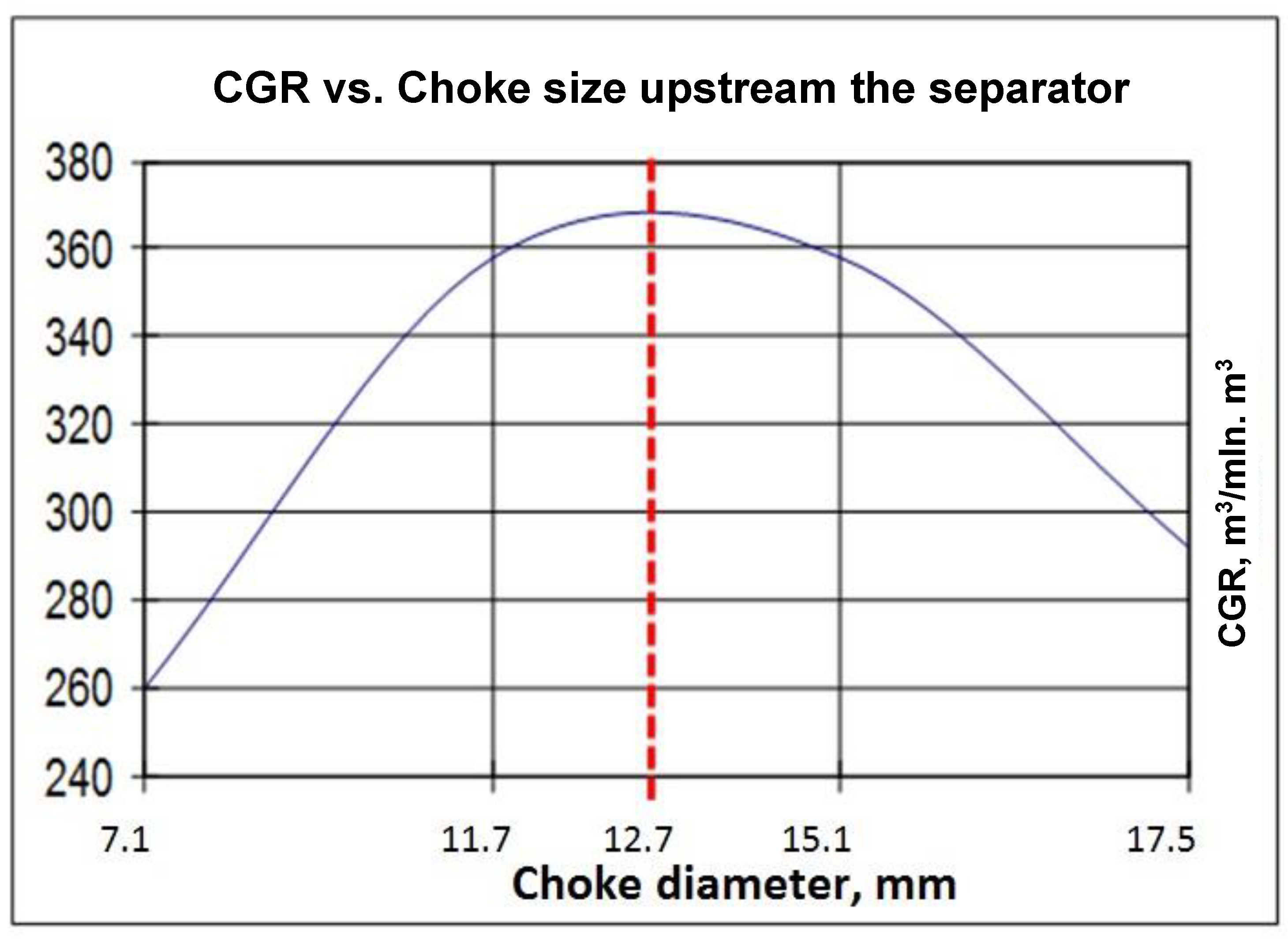
The reservoir fluid at the gas condensate field is initially in a single-phase gaseous state, provided that the reservoir pressure is above the dew point. The original reservoir gas composition (before phase segregation has started) contains a maximum of heavy molecules. Therefore, it is very important to carry out sampling and gas condensate studies before the initiation of the field development, until the reservoir pressure has decreased. The experience of testing gas condensate wells in various modes shows that at low flow rates (when the well operates on a smaller choke), the reservoir energy is not enough to carry the liquid phase to the surface. At a high flow rate, the CGR value also decreases due to the turbulent regime in the bottom hole zone and the peculiarities of the gas-hydrodynamics of the formation. The effective gas permeability due to the slip effect in the pores of the collector is higher than for liquid [
15]. The value of effective gas permeability k
g is related to the pore pressure, and formally this relationship is expressed as:
where b is the Klinkenberg constant (slippage factor); p
a is the average pressure in determining the gas permeability; k
l is the effective liquid phase permeability. Gas slippage effect increases as rock permeability coefficient and reservoir differential pressure decrease [
16]. At the maximum output of heavy condensate fractions to the surface, the component composition of the mixture will be closest to the initial composition of the formation fluid. It has been experimentally shown that for each well it is possible to find an optimal flow regime, where the CGR value will be maximum (
Figure 3). This regime is optimal from the point of view of field development and for increasing condensate recovery factors.
Permanent monitoring of reservoir parameters P, T, Q(g,c,w) provides the ability to comply with the required production regime, in which the extraction of heavy fractions will be maximum. Otherwise, the heavy, and most valuable, hydrocarbon fractions will remain in the reservoir as hard to recover. In addition to direct economic losses from under-produced condensate, this will lead to a premature decline in well productivity. The phenomenon of liquid loss (condensate) due to a drop of reservoir pressure below the dew point is known as retrograde condensation. As a result, the pore space of the reservoir is filled with a relatively slow-moving condensate fraction, and a condensate bank is formed that prevents the migration of formation fluids from remote areas of the formation to the wellbore. As the depression cone expands, the two-phase state area occupies an ever-larger annular space and actually creates a remote “skin effect”. There are several methods, which may help to overcome the condensate banking effect in well. Some approaches include the injection of solvents and chemicals to alter formation wettability to minimize condensate blockage [
17,
18,
19]. A recent study [
19] showed that developing a flowback system based on the formation of physical properties differentiation to control water phase invasion, and changing wettability or injecting thermochemical fluid to control condensate blocking are feasible methods to relieve liquid phase blockage damage in tight condensate reservoirs. Other methods include acid injection [
17], fracturing treatments [
20], and drilling horizontal wells to enlarge drainage areas. These methods will lower the rate of pressure drop and permit the production of a single-phase gas. The most effective techniques for combatting the condensate bank are hydraulic fracturing and pumping the formation with dry gas [
17,
21] and chemical treatment with methanol [
22] or novel developed surfactants [
17,
18].
Obviously, in order to increase condensate recovery, the combination of several different technologies will have a synergistic effect. In this regard, production optimization by controlling CGR with multiphase flow meters is a great addition to any problem-solving approach.
7. Application Prospects
The process of physical recombination of MIKS samples is simple. The usual conditioning of samples in the laboratory on an automatic rocking device at a pressure above the reservoir pressure and a temperature equal to or higher than the reservoir temperature for several days is sufficient for the sample to return to a monophasic gas state and be suitable for research in a PVT cell. Since the sample was taken in the flow mode with the maximum CGR value, the molecular-fractional composition of this emulsion will be close to the composition of the formation fluid. The same fluid that enters the well from the formation actually passes through the metering line, but in a homogenized form. In this case, the fractional composition of the gas-liquid mixture, temperature, pressure, and flow are continuously monitored on the flow meter. The efficiency of obtaining reservoir samples and the process of their physical recombination makes it possible to conduct PVT studies directly on the drilling platform or in a mobile field laboratory and obtain a complete PVT report even before the completion of drilling and conservation of the well. An additional economic effect is achieved by reducing the cost of transporting and storage of samples.
When testing exploration and appraisal wells on the Arctic shelf, the issue of minimizing the dimensions and weight of deck equipment and reducing the time of work is especially acute. The traditional set of deck test equipment, including a steam heat exchanger, a test separator, storage tanks for separated oil (or condensate), transfer pumps, burners, and piping, is too bulky and expensive to maintain, requires considerable time and a large team (10–12 people) for preparatory work—rig-up of piping, pressure testing and functional testing of all modules. Actually, there may simply not be enough time to test a well (reservoir) due to the short Arctic summer.
8. Primary Production Treatment
Another important problem, especially relevant for the macro-region of Eastern Siberia, is—how to involve small and remote oil and gas fields into profitable production in the regions? There may be practically no infrastructure, but there is high potential for the development of the mining industry and other types of industries. The problem can be solved by developing a network of modular complexes for the production of fuels and lubricants, operating in a closed cycle system directly at the fields [
23]. The production chain includes the extraction of hydrocarbon raw materials, preparation and purification of products with their subsequent use in modular thermo-catalytic cracking units for the production of arctic types of fuels and lubricants, as well as environmentally friendly utilization of gas and produced water.
An important link in this chain is the early produced oil treatment systems—EPF (Early Production Facility) that allow producing companies to recoup the initial investment in the development of a field at an early stage, when the feasibility of large investments in the creation of a full-scale infrastructure has not yet been proven. They include high-performance heat exchangers, separators, gas, and oil purification systems from hydrogen sulfide and sulfur, oil desalination and dehydration modules, compressors, pumps, storage tanks for products, and treatment or utilization of associated gas. The technological scheme of the primary well production treatment unit in the basic configuration is functionally similar to the surface complex for well testing (
Figure 4). To solve the problem of environmentally friendly testing, systems with gas recirculation (Asset Capturing System, Weatherford, Houston, TX, USA), without burning gas into the atmosphere, are world widely used.
In addition to the main units shown in the diagram, the facility should include all necessary auxiliary systems, in particular, control and emergency shutdown (ESD), fire and gas control, chemical injection, power generation, compressed air for pneumatic tools, and control devices. The method of shipment of finished products from the EPF treatment plants is determined by the customer (pipeline, tankers, trucks). The performance of EPF complexes may vary significantly depending on the scale of production and range from 300 to 20,000 m3/day for liquid (oil + water), and from 0.2 to 10 million m3/day for gas. At the outlet of the primary oil treatment system, the quality of hydrocarbons is usually high enough for direct loading into the thermal cracking system (mass fraction of formation water is not more than 0.5%). To remove dissolved salts from oil, followed by washing and drying, it can be supplemented, if necessary, with electric desalters and dehydrators.
9. Waste-Free Production of Fuel and Lubricants in the Oil & Gas Fields
Nowadays, the problem of reducing the emission of carbon dioxide and other greenhouse gases is especially relevant. One of the main ways to reduce the carbon footprint is to use waste-free (or low-waste) technologies. The concept of the closed loop production cycle is an emerging megatrend in the world economy that can contribute to climate change mitigation, according to experts from the OPEC Secretariat. The use of modular complexes for practically waste-free production according to a closed cycle scheme in order to obtain fuels and lubricants directly at oil & gas fields fits perfectly into the framework of this new global environmental and economic paradigm. This approach will not only involve remote “unprofitable” hydrocarbon deposits in production, but also reduce emissions of harmful gases and, as a result, a cross-border energy taxes. The involvement of “non-industrial” reserves in profitable production would solve a number of key problems that impede the systematic development of vast unexplored territories rich in various ore and non-metallic minerals and other natural resources. The innovative technological solutions described in [
23,
24] could become the basis for the successful implementation of federal programs for the development of remote regions.
The production mini-complex for the production of fuels and lubricants includes the following components of the technological chain (
Figure 5): (1) a system for monitoring production wells and separating products (oil-water-gas mixture) → (2) additional oil treatment (if necessary) → (3) desulphurization of oil and associated gas (if necessary), → (4) production of a wide range of fuels and lubricants at modular catalytic cracking units, → (5) use or environmentally friendly disposal of waste—associated gas and produced water (
Figure 5). All elements of this chain are represented by relatively compact modular blocks that can be delivered to the field by winter road or by a cargo helicopter and are designed for year-round autonomous operation in harsh conditions.
The optimal volume of oil production for the full load of one modular mini-system for the production of fuel and lubricants (step No. 4,
Figure 5) is 15–20 thousand tons of oil per year (or up to 50 tons of oil per day). As a result of deep processing of the locally produced raw materials, in this case, up to 16 tons/day of winter diesel fuel with a pour point below −35 °C, a cold filter plugging point (CFPP) below −25 °C, or up to 10 tons/day—Arctic diesel fuel (with a pour point below −55°C, CFPP below −45 °C), as well as Euro-3 gasoline, oil, and bitumen. A brief description of the necessary equipment for the extraction and primary treatment of oil and gas is presented below, and the technological schemes for the mini-production of fuels and lubricants (development by LLC NPO Energomashautomatika
https://www.npoema.ru, accessed on 1 April 2017 with partners), using oil, condensate or gas as raw materials are given respectively in papers [
23,
24]. To ensure year-round operation of equipment at a small field, a small installation with one set of catalytic thermal cracking, consuming up to 150 tons of raw materials (oil) per day, with a capacity of up to 50 tons of winter diesel fuel per day, will be sufficient.
10. Disposal of Produced Water
The problem of environmentally friendly disposal of produced water is usually solved by re-injection into the reservoir through injection wells. Injection, as a rule, is carried out according to the scheme of edge flooding in order to maintain reservoir pressure and uniform displacement of oil from the reservoir. At the outlet of the primary oil treatment system (after separation and purification), the quality of the raw material, as a rule, is good enough for direct loading into the catalytic thermal cracking system. The mass fraction of formation water at the separator outlet does not exceed 0.5%. In some cases, preliminary desulfurization (desulfurization) of products may also be required.
11. Desulfurization
To purify gas and oil from hydrogen sulfide and mercaptans, a native technology based on catalytic processes has been developed, which makes it possible to improve product quality and key environmental indicators while reducing costs relative to world leaders in desulphurization technologies [
25]. This process eliminates the use of classic Claus and MEROX processes and has been proven in the oilfields. The catalytic desulfurization method provides a multiple reduction in the number of technological stages, material consumption of equipment, and unit costs at very high-quality indicators. The technology is based on the process of catalytic oxidation of hydrogen sulfide and mercaptans to sulfur and disulfides, respectively:
Using this method of catalytic purification, it is possible to convert hydrogen sulfide and mercaptans into a compact and convenient form for transportation in one or two stages. Crude oil mixed with hydrogen sulfide enters the tank for purge with purified gas, which absorbs hydrogen sulfide. The purified oil is sent for processing, and the gas goes to the unit for catalytic purification and utilization of hydrogen sulfide, where, after the oxidation of H
2S, pure sulfur is obtained at the output. The purified gas is used repeatedly in the cyclic oil refining process [
23].
12. Utilization of Associated Petroleum Gas
For the utilization of associated petroleum gas (APG), gas turbine (GTPP) and gas piston (GPPP) power plants are widely used. However, the presence of heavy hydrocarbons in the composition of associated gas adversely affects their operation, which leads to a decrease in nominal productivity and overhaul run. The use of microturbine power plants will allow more efficient use of associated petroleum gas as a fuel. An example of the successful use of modern high-tech Russian-made systems for gas separation can be research & production company Grasys
https://www.grasys.com/products/gas/hydrocarbon/fuel, accessed on 1 April 2020, which manufactures equipment for the purification of associated gas from water, sulfur compounds, and heavy hydrocarbon fractions, preparation, and processing of natural and associated gases based on a polymer membrane of their own design CarboPEEK™ [
26].
If there is no possibility of selling dry stripped gas to a third-party consumer, and the need for heat and electricity in the field is small, the only economically viable solution in modern conditions is to inject gas into the reservoir in order to intensify oil (condensate) production. In the development of gas condensate fields, in order to maintain reservoir pressure and combat the condensate bank in the reservoir, the cycling process (CP) is used—the re-injection of dried gas into the productive horizon. In this case, the gas produced in this field is normally used after the extraction of high-boiling hydrocarbons (C5+) from it. The cycling process is used when it is possible to preserve the gas reserves of a given field for a certain period of time. The predicted recovery factor of condensate from the reservoir at full CP reaches 70–80%. Partial CP is also used, where the ratio of volumes (reduced to reservoir conditions) of injected and withdrawn gases is 60–85%. The condensate recovery factor may reach 60–70% [
27].
If there is a processing mini-plant at the field, part of the dried gas is used to support the process of thermal catalytic cracking. Partially, gas can be used to generate electricity at gas incinerators and power plants. In recent years, certain success has been achieved in the development of methods for processing lean mixtures. In this regard, it should be noted the creation of volumetric burners based on pressed wire material (PWM), developed and manufactured by REAM-RTI (Russia)
https://ream-rti.ru, accessed on 1 April 2016. Such devices make it possible to increase the efficiency of associated gas utilization while significantly reducing the amount of toxic emissions. On the other hand, the use of PWM, according to preliminary results, makes it possible to carry out the process of obtaining synthesis gas from methane in a relatively small-sized application. This creates real prerequisites for the implementation of the Fischer-Tropsch process in a container design, suitable for use directly in the field.
Synthesis gas (a mixture of CO and H
2) has been used for about 100 years to produce synthetic fuels and lubricants, including methanol. Methanol injection is one of the most effective ways to restore the permeability of a gas condensate reservoir by cleaning the pore space of the reservoir from condensate [
22]. Thus, the cost of operations to increase oil and condensate recovery of the formation can be significantly reduced due to the synthesis and use of methanol directly in the field. Infrared gas burners are more economical than flare gas burners, since they reduce gas consumption by 30–50% at the same power. They are also more environmentally friendly, as they reduce the toxicity of exhaust gases by 10% or more. Infrared gas burners with a PWM matrix differ from ceramic matrices in impact resistance, mechanical strength, and elasticity. The PWM structure is an interweaving of specifically oriented wire spirals, which, as a result of successive cold pressing in special molds, form an open-pore system permeable in all directions, providing the required mechanical, physical, and hydrodynamic parameters [
24]. The use of new types of materials in catalysis made it possible to proceed with the development of new designs of reaction devices (small volume reactors). The design of the reaction device with the use of high-performance catalytic systems leads to a significant reduction in the material and energy consumption of production, a decrease in the negative impact on the environment, and a decrease in the risk of man-made disasters.
Thus, there are several ways of environmentally friendly utilization of associated gases, which enable termination of their flaring. This makes it possible to stop atmospheric pollution and rationally use the additional volume of hydrocarbon resources.
13. Conclusions
The proposed reservoir fluid sampling method—MIKS (Multiphase IsoKinetic Sampling)—is easy to implement, cost-effective, and allows solving the problem of obtaining representative reservoir samples of near-critical fluids—gas condensate and volatile oil. It can serve as an alternative to downhole and separator sampling. The compactness, information content, and performance of the system opens up new opportunities in offshore well testing, in particular, on the Arctic shelf.
The combined use of MIKS technologies and multiphase flow metering is a way to solve another major problem in the development of gas condensate fields—overcoming the condensate bank that forms around production wells. The idea of optimizing gas condensate production is to maintain the well operation mode with the maximum gas-condensate ratio, which requires constant multi-phase monitoring of well production using multi-phase flow meters. To overcome the formed condensate bank, it is advisable to use methods to increase condensate recovery—hydraulic fracturing to destroy the condensate barrier, followed by a cycling process—purging the formation with dried gas and/or injection of methanol into the formation. Methanol can be obtained from synthesis gas as a by-product in the utilization of associated gas also at the field. The specified set of measures will allow for reviving the GC wells that are losing productivity, as well as extending the period of high productivity of new wells.
A waste-free technology for obtaining winter types of fuels and lubricants at small and remote fields using modular installations for product preparation and thermal catalytic processing of raw materials is a cost-effective solution for involving “unprofitable” hydrocarbon deposits in the production and providing remote areas with local energy resources. This approach will contribute to the economic development of remote regions due to the steady expansion of the road network, the development of infrastructure, and energy-consuming industries—mining, metallurgy, etc.


