
Review on Integrated On-Board Charger-Traction Systems: V2G Topologies, Control Approaches, Standards and Power Density State-of-the-Art for Electric Vehicle

 ,
,  ,
, 
 , and
, and 
Abstract
:1. Introduction
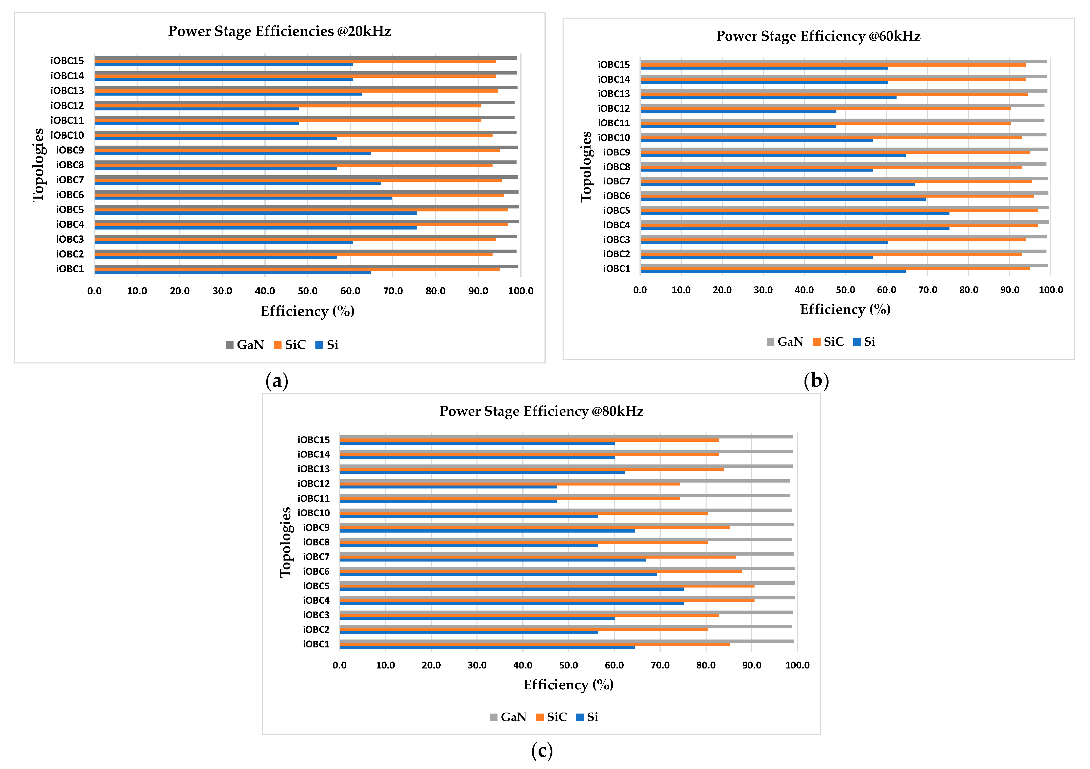
- Detailed analysis of the recently developed bidirectional iOBC topologies including advantages, disadvantages, available features, and efficiencies with different switch technologies.
- Comparative investigation of charging and driving mode control strategies used in iOBCs including overshoot and dynamic response.
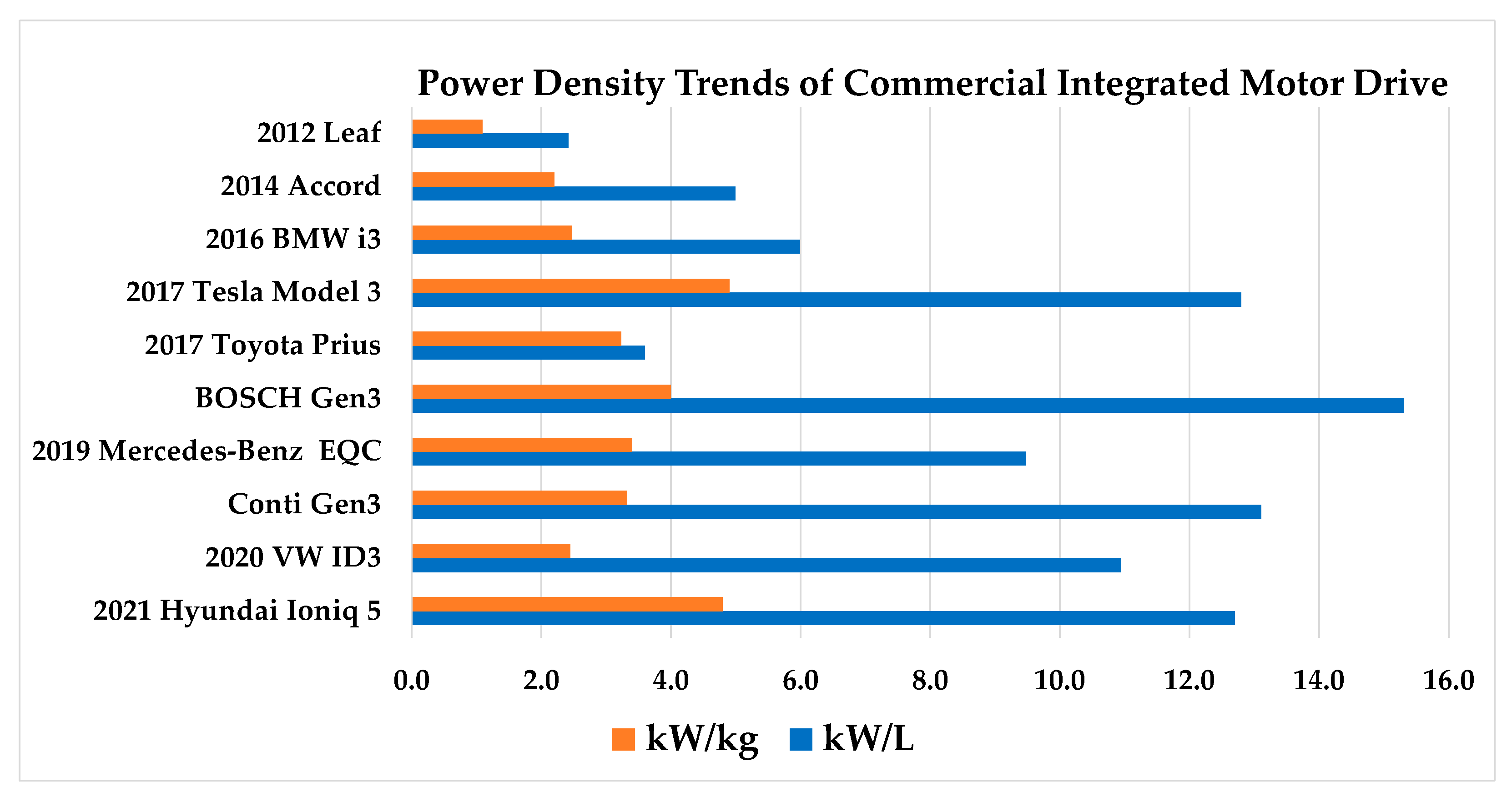
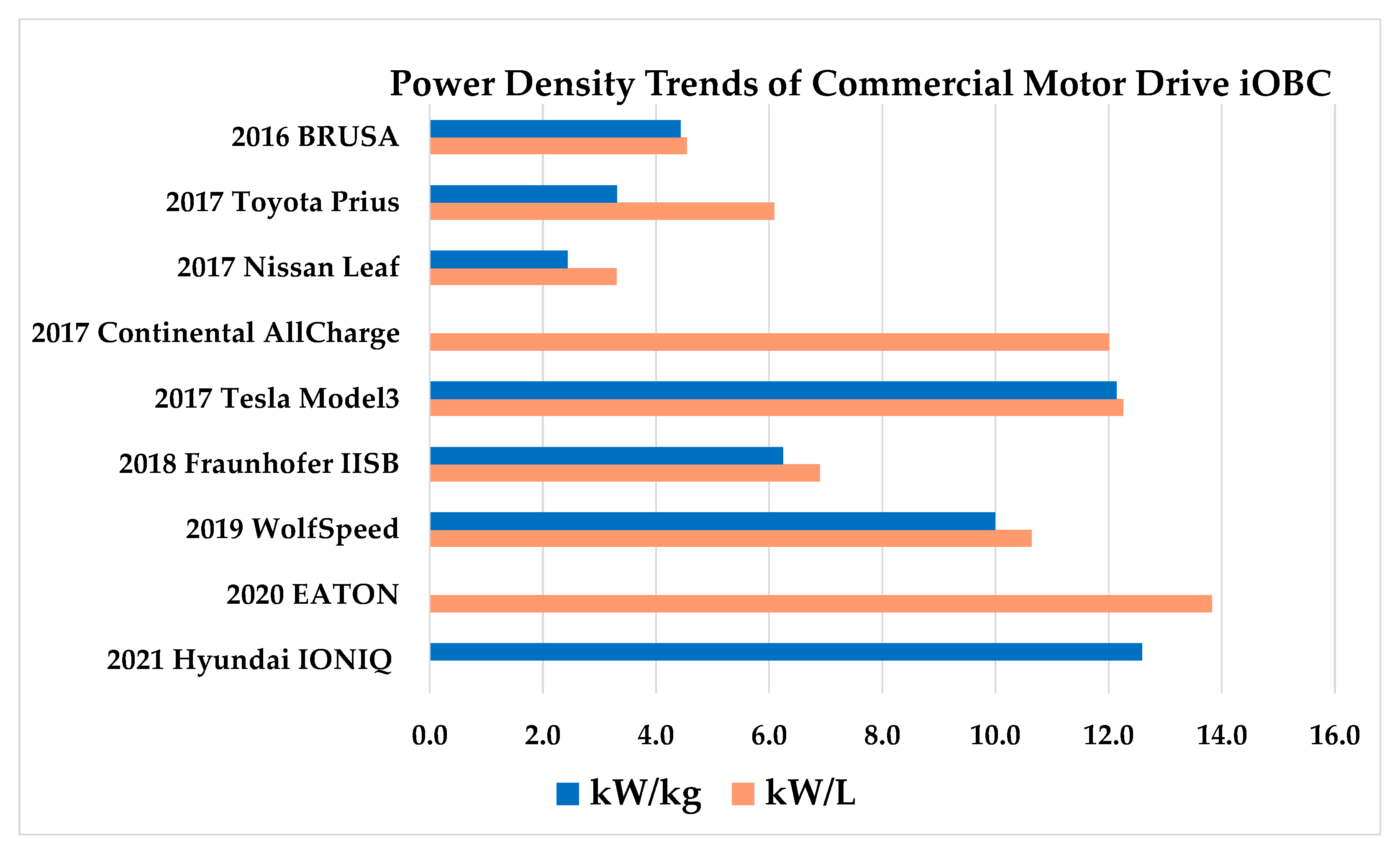
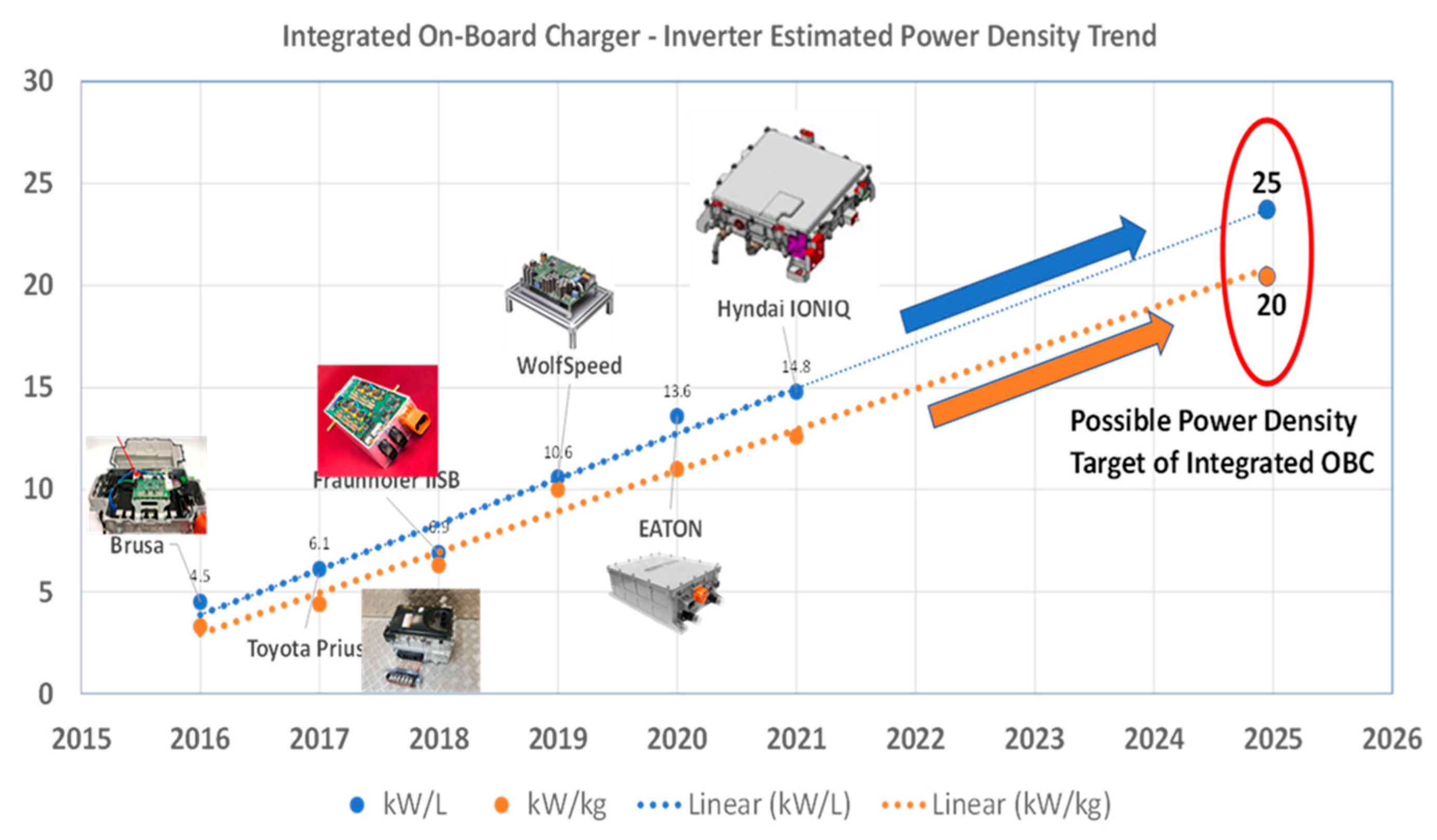
- Summary of the requirements and estimated power density trends of commercial integrated charging solutions.

| Region | Year | EV Model | Ref. | Motor Power (kW) | Battery Capacity (kWh) | Charging Time | Max. OBC Rating (kW) |
|---|---|---|---|---|---|---|---|
| Europe | 2021 | Hyundai IONIQ 5 | [20] | 160 | 73 | 6 h 9 min | 11 |
| 2021 | BMW X3 | [21] | 125 | 43 | 3 h 15 min | 11 | |
| 2021 | Nissan Leaf | [22] | 110 | 40 | 3 h 22 min | 11 | |
| 2021 | VW ID4 Pro S | [23] | 150 | 82 | 7 h 30 min | 11 | |
| 2021 | Audi e-Tron | [24,25] | 230 | 71.2 | 7 h 07 min | 11 | |
| 2020 | Renault Zoe R135 | [26] | 100 | 54.66 | 2 h 22 min | 43 | |
| 2021 | Mercedes Benz EQA | [27] | 140 | 66.5 | 5 h 45 min | 11 | |
| US | 2021 | Tesla Model Y | [28,29] | 201 | 75 | 7 h 30 min | 11/22 |
| 2021 | Chevy Bolt | [30] | 150 | 66 | 10 h | 6.6 | |
| 2021 | Porsche Taycan Turbo S | [31,32] | 190 | 93.4 | 10 h 30 min | 11 | |
| China/ Japan | 2017 | BAIC EC180 | [33] | 30 | 22 | 2 h 14 min | 11 |
| 2020 | Chery eQ | [34] | 30 | 32 | 3 h 14 min | 11 | |
| 2019 | JACK iEV7 S/E | [35] | 50 | 24 | 2 h 26 min | 11 | |
| 2017 | JMC E200 | [36] | 30 | 17.3 | 1 h 45 min | 11 |
| Charging Level | Voltage Level | Max Power (kW) | Charging Time | China | Europe | Japan | North America |
|---|---|---|---|---|---|---|---|
| Level 1 | 120 VAC | 3.7 | 10–15 h | Private Outlet (Not Specific for EVSE) | SAE J1772 T1 | ||
| Level 2 | 220 VAC | 3.7–22 | 3.5–7 h | GB/T 20234 AC | IEC 62196 T2 | SAE J1772 T1 | SAE J1772 T1 |
| Level 3 | 480 VAC (US)/400 VAC (EU) | 22–43.5 | 10–30 min | GB/T 20234 AC | IEC 62196 T2 | SAE J3068 | |
| 200–600 DC | <200 | 10–30 min | GB/T 20234 DC | CCS Combo 2 | CHAdeMO | CCS Combo 1 | |
| <150 | 10–30 min | Tesla and CHAdeMO | |||||
| XFC | >800 VDC | >400 | H2 Gas refueling | CCS/CHAdeMO | |||
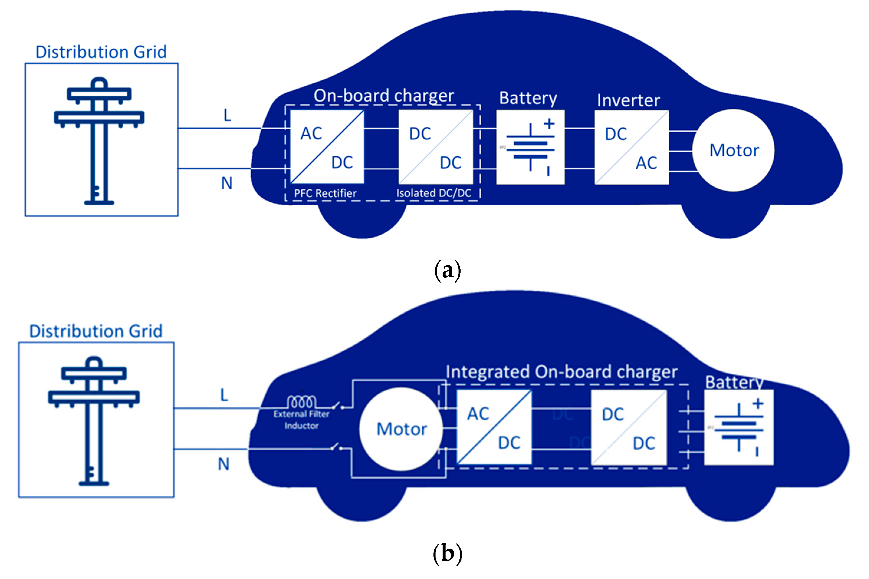
2. On-Board Charger Integration Methods
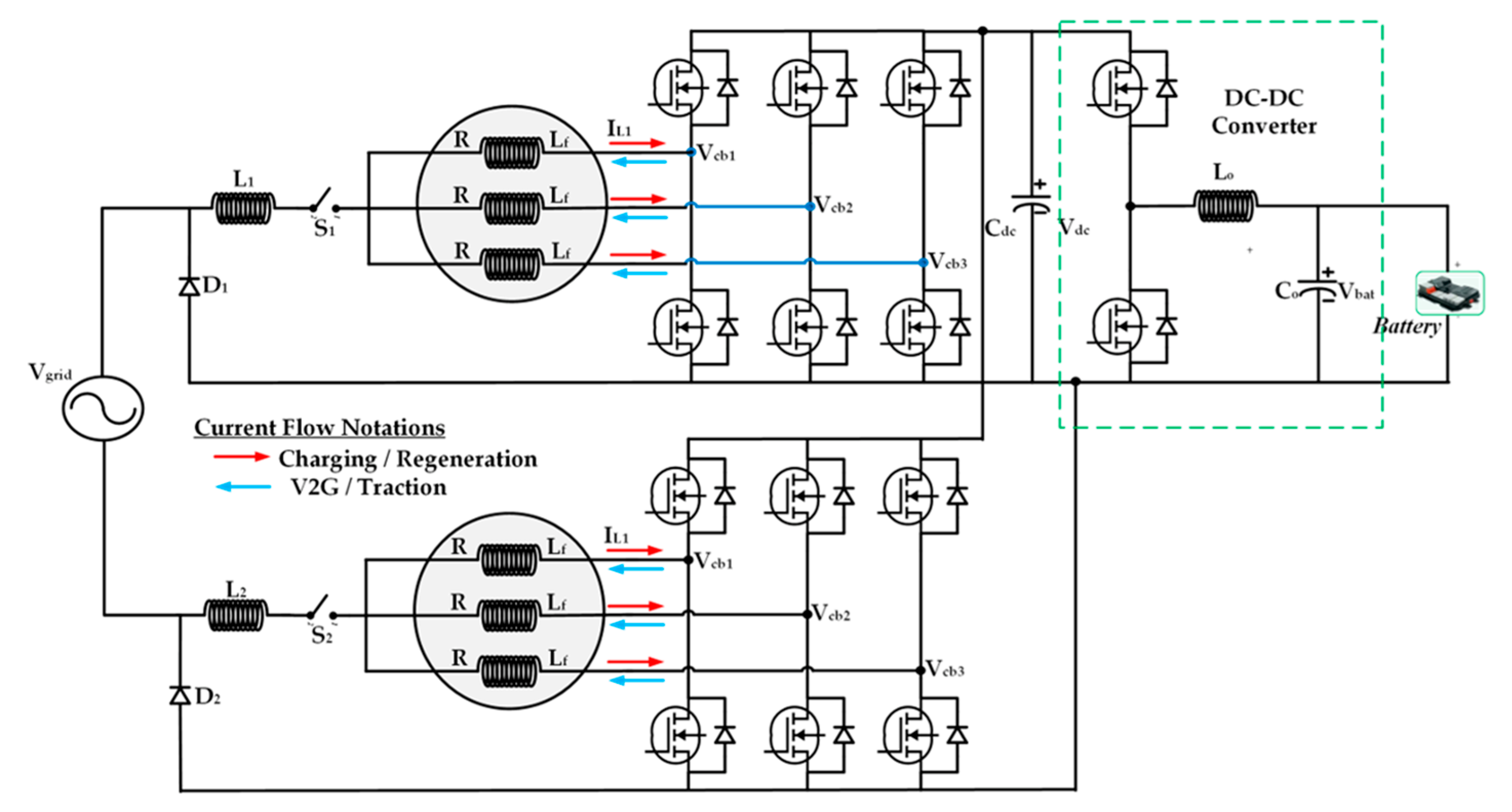
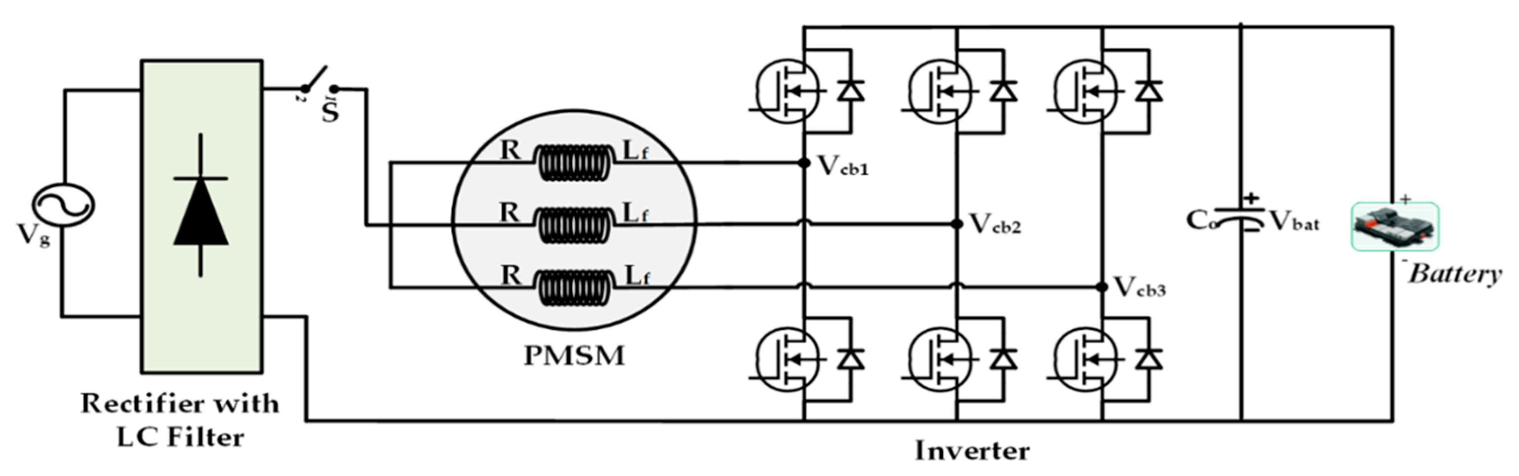
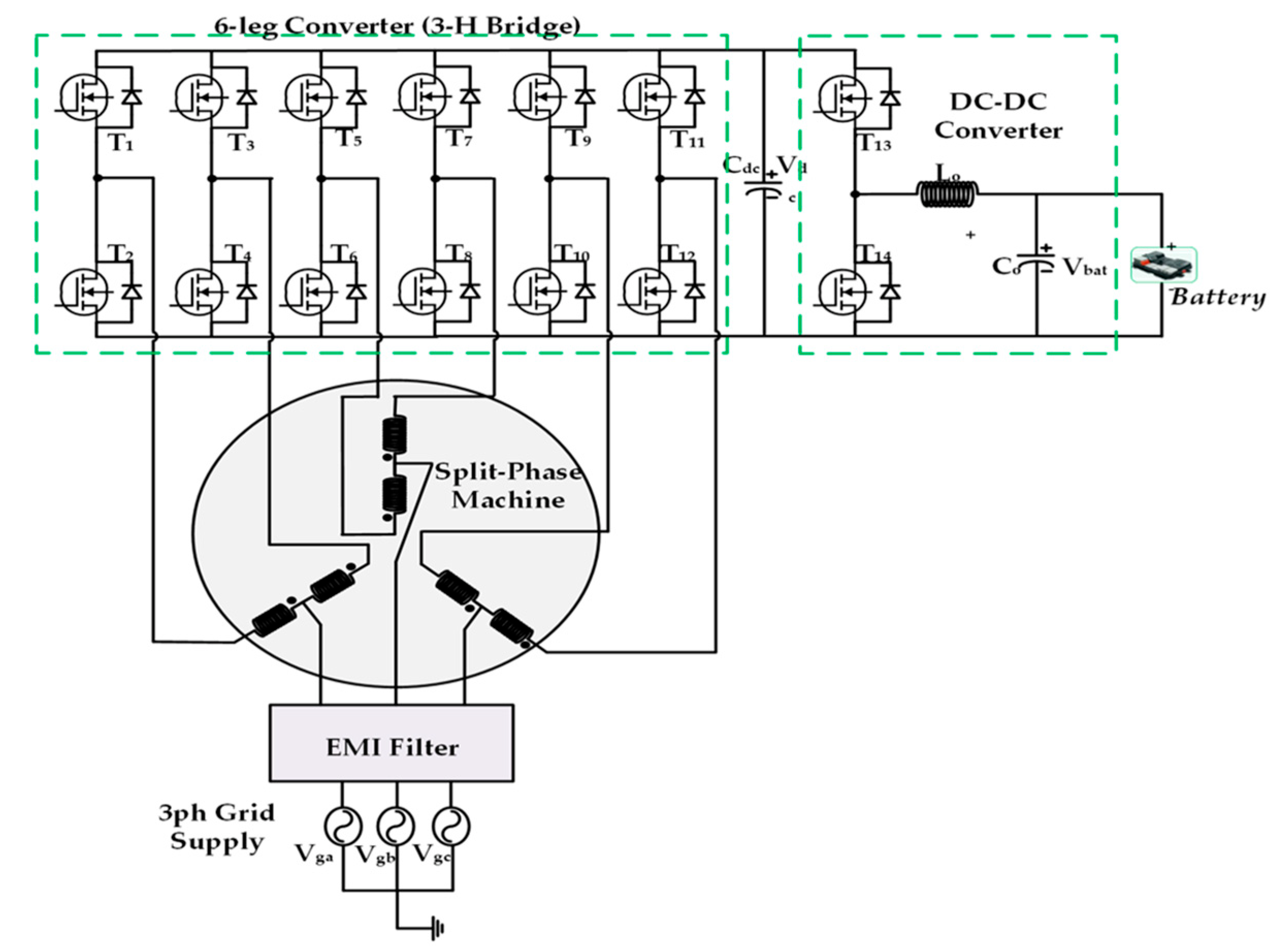
3. Integrated On-Board Charger (iOBC) Topologies
4. Control Techniques for iOBC
4.1. Charging Mode Controls forAC/DC Converter
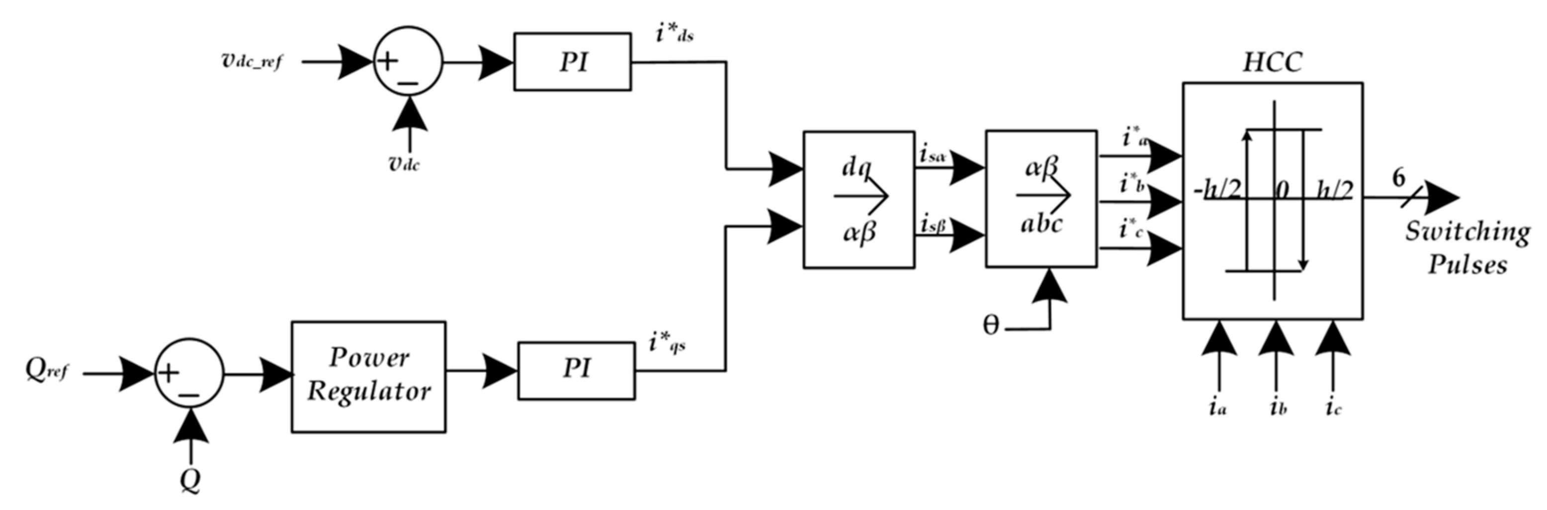
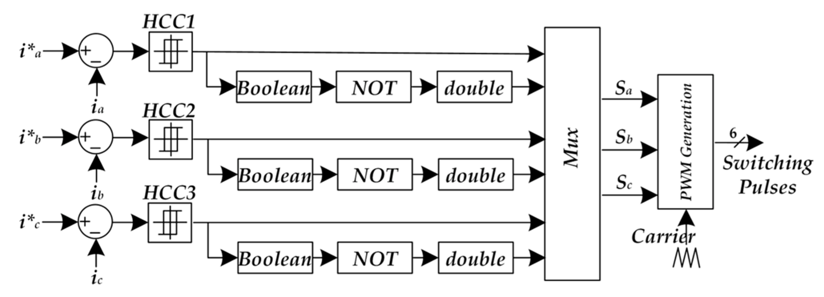
4.1.1. Hysteresis Current Control (HCC)
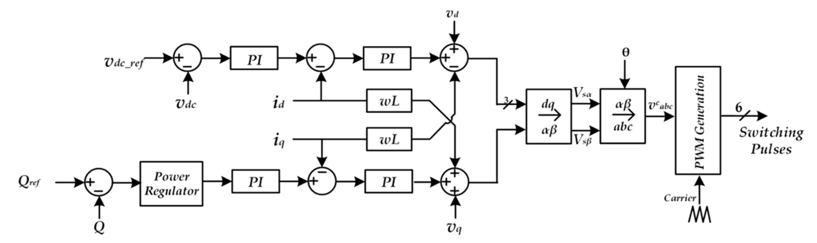
4.1.2. Proportional-Integral (PI) Based Dual Loop Control
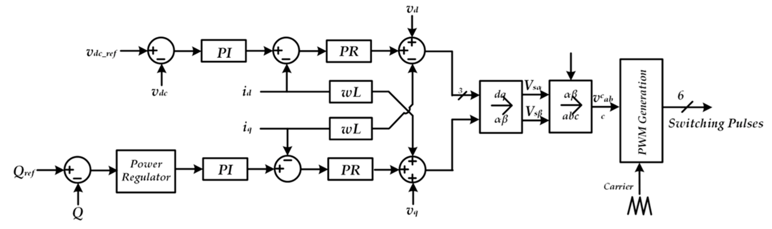
4.1.3. Proportional-Resonant (PR) Based Dual Loop Control
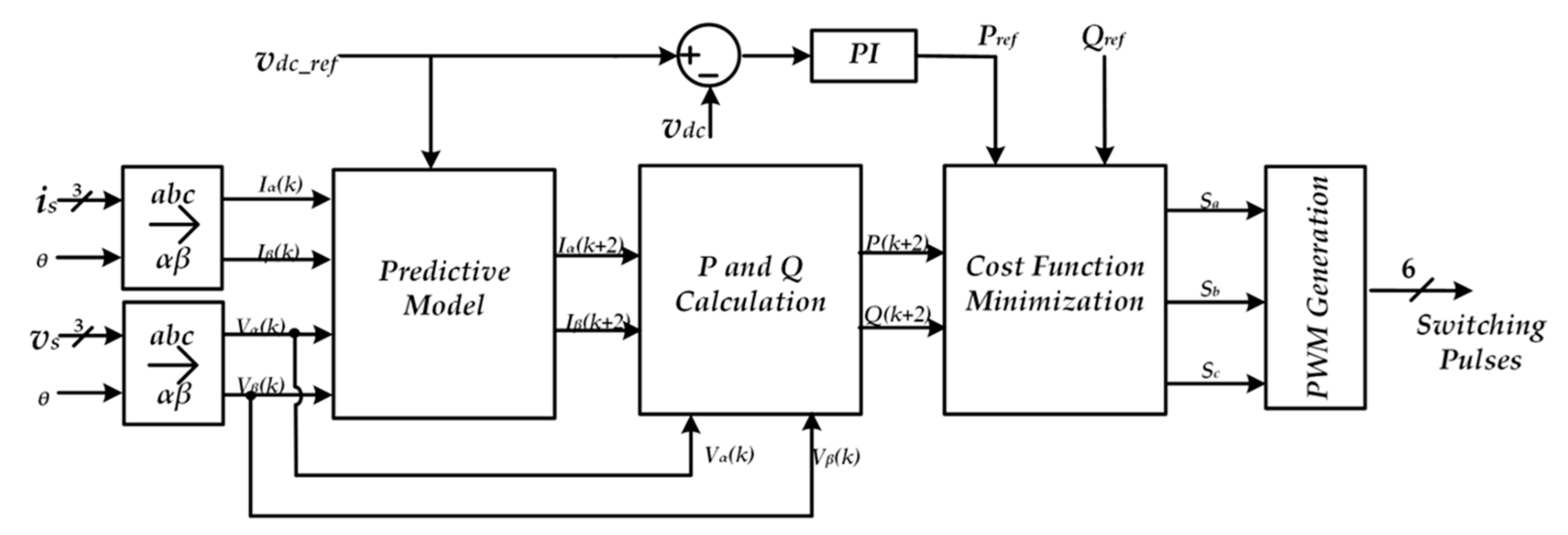
4.1.4. Model Predictive Control (MPC)
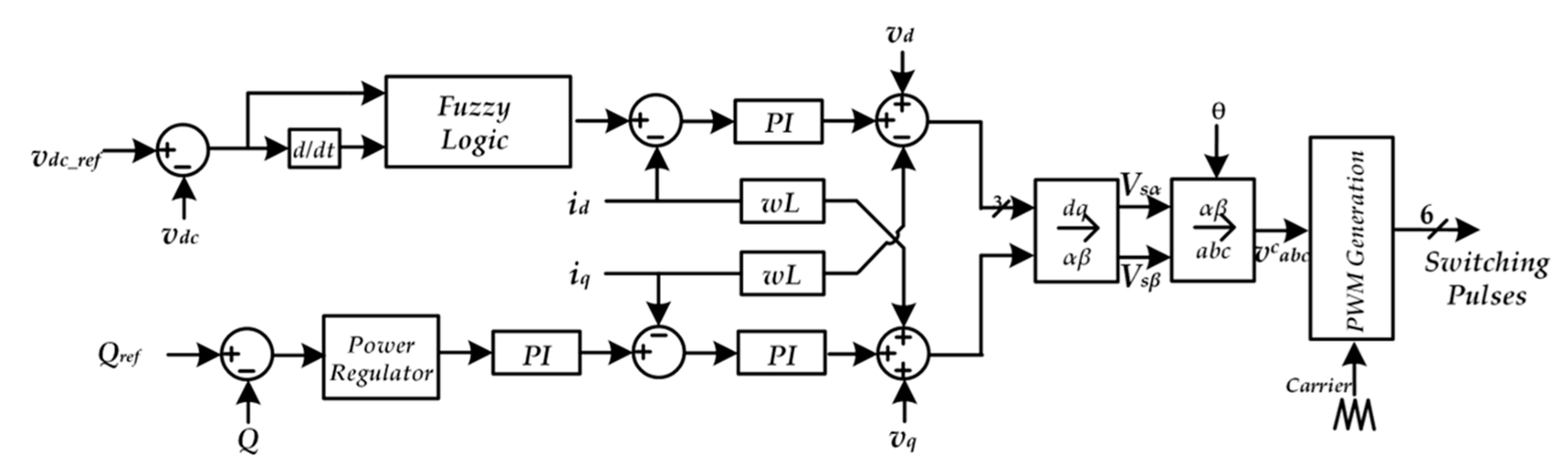
4.1.5. Fuzzy Based PI Control
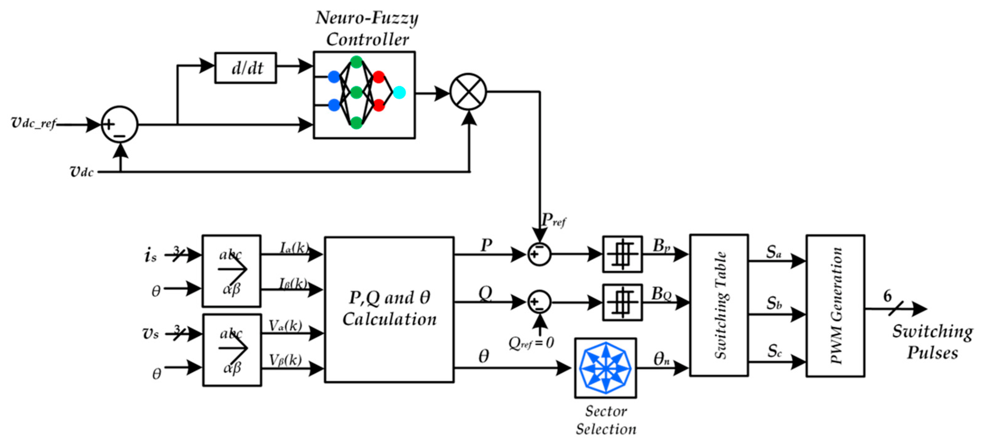
4.1.6. Neuro-Fuzzy Control
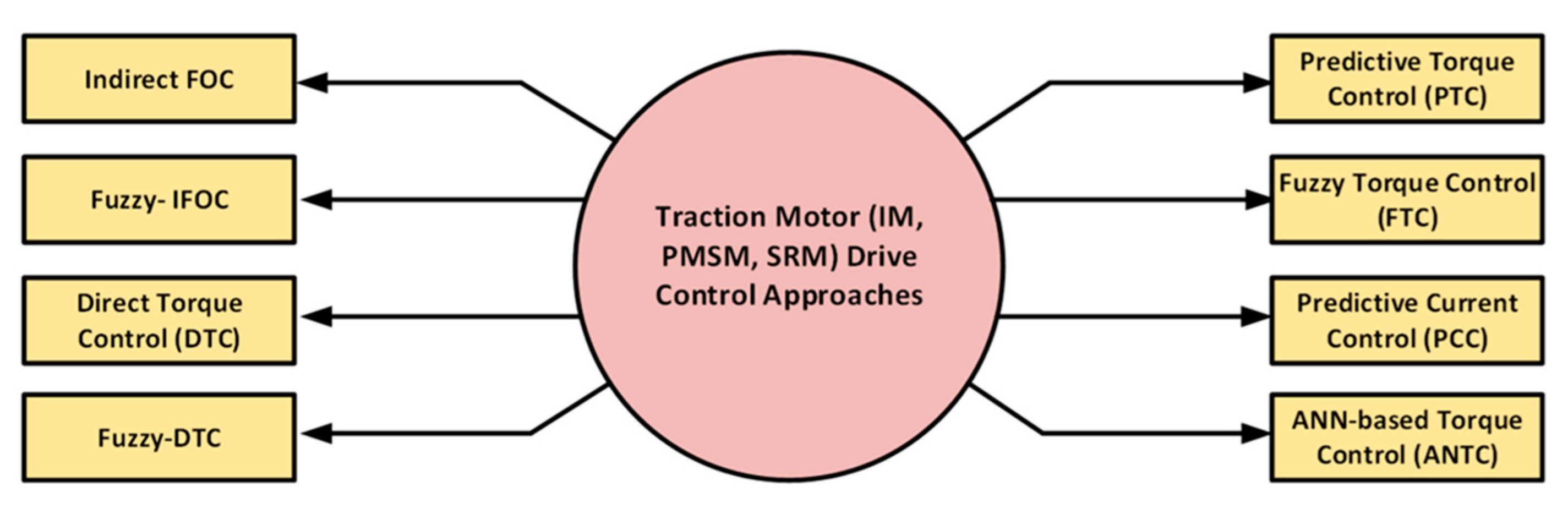
4.2. Driving Mode Control for DC/AC Inverter
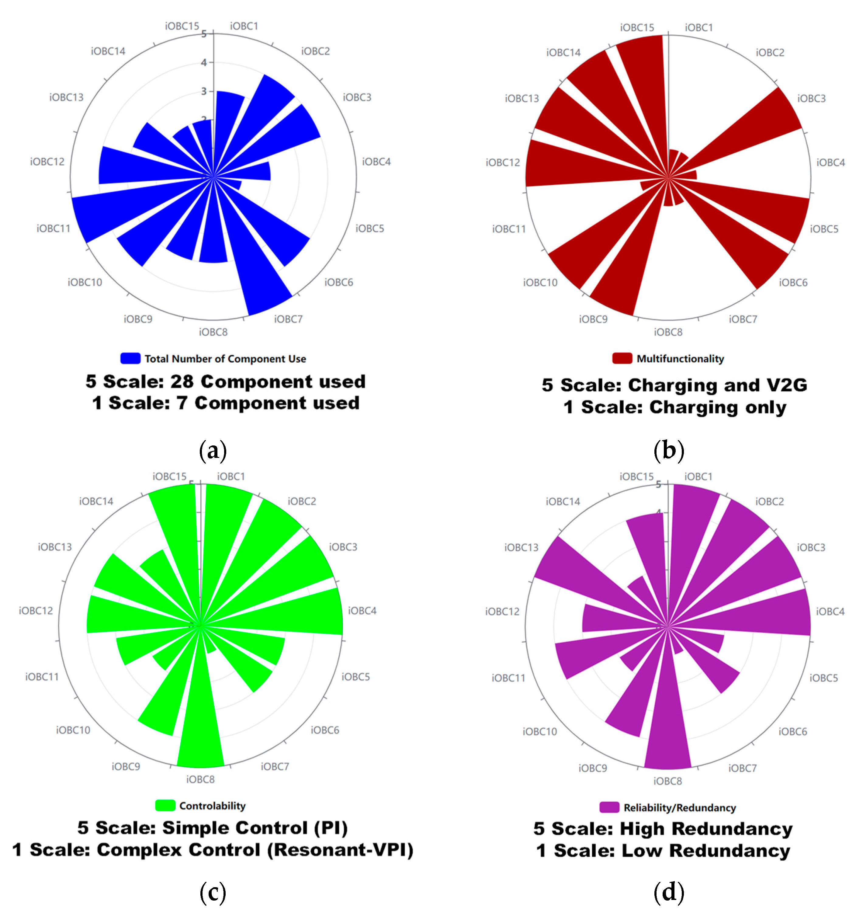
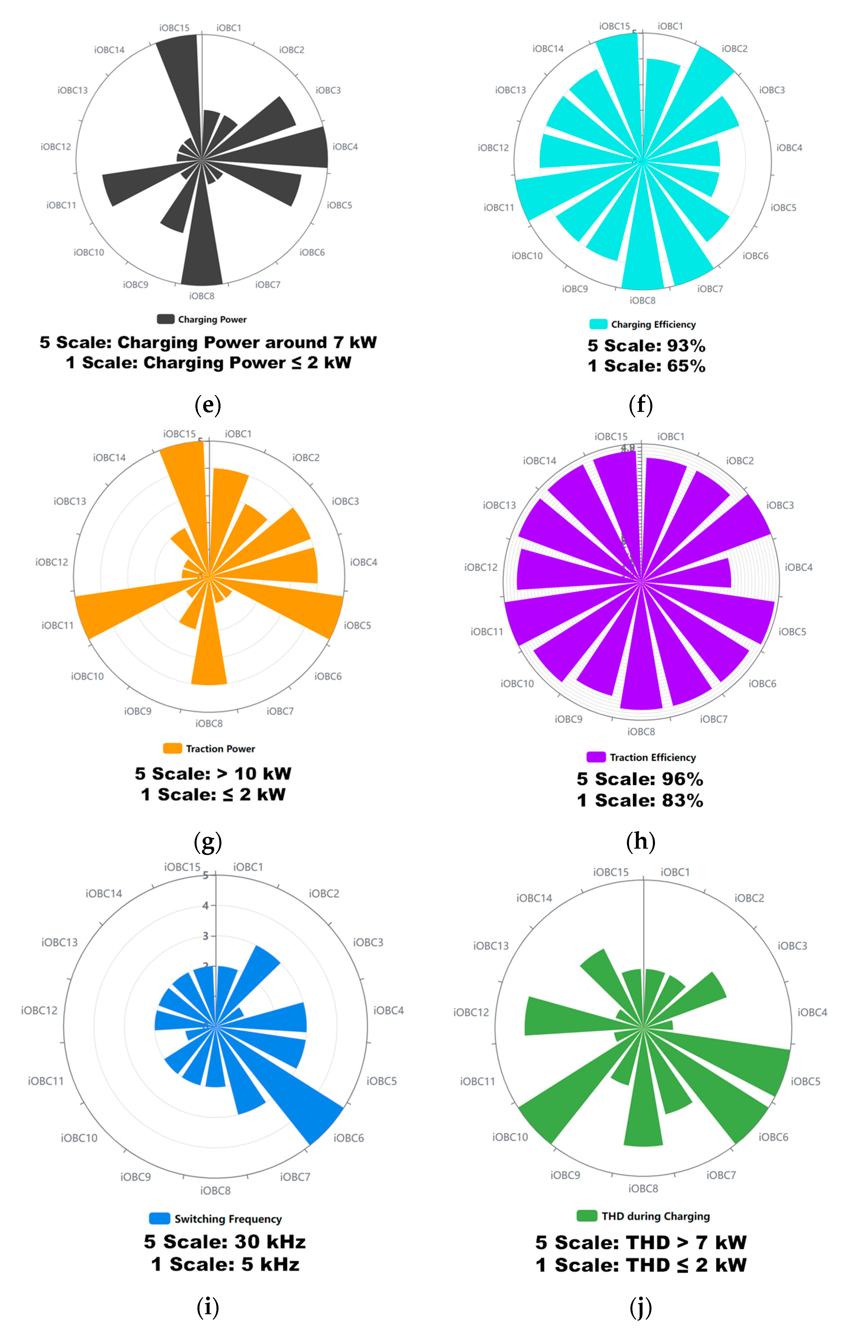
5. Comparative Analysis and Discussions
6. Electric Vehicle Charging Standards
7. Integrated On-Board Charger Power Density SoTA
8. Economic and Environmental Impact of iOBC
- The implementation of iOBC solution will strengthen the competitiveness of EU companies, particularly the OEMs which can benefit from the commercialization of developments.
- The car manufacturers will be able to increase their turnover due to sales of innovative products, subsequently enhancing their positioning in the EV worldwide market by using innovative iOBC solutions.
- The component level OEMs will be able to sell new services related to their testing business, also enhancing their infrastructure and labs for unique positioning of novel bidirectional testing activities.
- This increase in competitiveness will be translated into maintaining jobs and expertise in Europe.
- Impact of modular, flexible and bi-directional iOBC systems in increasing EVs adoption
- ✓
- Improved charging procedures without increasing battery size/price
- ✓
- Improved user-friendliness and contribution to meeting end-user expectations
- ✓
- Reduce costs on infrastructure side
- ✓
- Generate new opportunities for the user
- ✓
- Impact on time to market and accelerated adoption
- Proven scalability and functionality with different vehicle brands and different vehicle segments presented in the state-of-the-art review of iOBC topologies for BEV and PHEV powertrains, including control.
9. Conclusions
Funding
Institutional Review Board Statement
Informed Consent Statement
Data Availability Statement
Acknowledgments
Conflicts of Interest
Abbreviations
| AFE | Active Front-End |
| ANN | Artificial Neural Network |
| ANNTC | Artificial Neural Network based Torque Control |
| BEV | Battery Electric Vehicle |
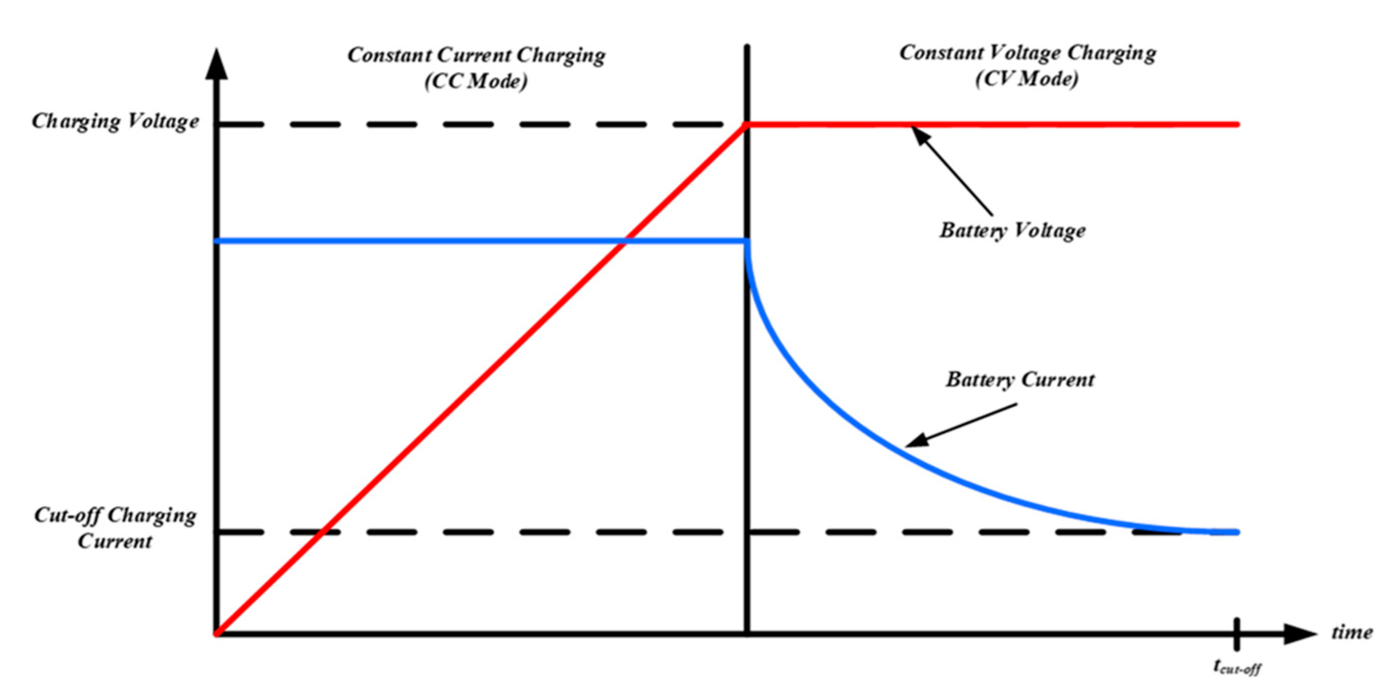
| CC | Constant Current |
| CM | Common Mode |
| CV | Constant Voltage |
| DSC | Digital Signal Controller |
| DTC | Direct Torque Control |
| EMI | Electromagnetic Interference |
| EV | Electric Vehicle |
| FL | Fuzzy Logic |
| FTC | Fuzzy based Torque Control |
| G2V | Grid-to-Vehicle |
| GaN | Galium Nitride |
| GB/T | Guojia Biaozhun/Tuijian (China) |
| HCC | Hyteresis Current Control |
| ICE | Internal Combustion Engine |
| IEC | International Electromechanical Commission |
| IEEE | Institute of Electrical and Electronic Engineers |
| IFOC | Indirect Field Oriented Control |
| IM | Induction Machine |
| iOBC | Integrated On-board Charger |
| ISO | International Organization of Standardization |
| JEVS | Japan Electric Vehicle Standard |
| MPC | Model Predictive Control |
| NFPA | National Fire Protection Association |
| OEM | Original Equipment Manufacturer |
| OEWM | Open-End Winding Machine |
| PCC | Predictive Current Control |
| PEV | Plug-in Electric Vehicle |
| PI | Proportional Integral |
| OEM | Original Equipment Manufacturer |
| OEWM | Open-End Winding Machine |
| PCC | Predictive Current Control |
| PEV | Plug-in Electric Vehicle |
| PI | Proportional Integral |
| PLL | Phase Locked Loop |
| PMSM | Permanent Magnet Synchronous Machine |
| PR | Proportional Resonant |
| PTC | Predictive Torque Control |
| SAE | Society of Automotive Engineers |
| SiC | Silicon Carbide |
| SRM | Synchronous Reluctance Machine |
| T1FLC | Type 1 Fuzzy Logic Control |
| T2FLC | Type 2 Fuzzy Logic Control |
| T2NFC | Type 2 Neural Fuzzy Control |
| THD | Total Harmonic Distortion |
| UL | Underwriters Laboratories Inc |
| V2D | Vehicle-to-Device |
| V2G | Vehicle-to-Grid |
| V2H | Vehicle-to-Home |
| V2V | Vehicle-to-Vehicle |
| VDE | Verband Deutscher Elektrotechniker (Germany) |
References
- Element Energy Limited. Electric Cars: Calculating the Total Cost of Ownership for Consumers; Element Energy Limited: Cambridge, UK, 2021; p. 44. [Google Scholar]
- Habib, S.; Khan, M.M.; Abbas, F.; Sang, L.; Shahid, M.U.; Tang, H. A Comprehensive Study of Implemented International Standards, Technical Challenges, Impacts and Prospects for Electric Vehicles. IEEE Access 2018, 6, 13866–13890. [Google Scholar] [CrossRef]
- Ahmad, A.; Alam, M.S.; Chabaan, R. A Comprehensive Review of Wireless Charging Technologies for Electric Vehicles. IEEE Trans. Transp. Electrif. 2017, 4, 38–63. [Google Scholar] [CrossRef]
- Trends and Developments in Electric Vehicle Markets—Global EV Outlook 2021—Analysis—IEA. Available online: https://www.iea.org/reports/global-ev-outlook-2021/trends-and-developments-in-electric-vehicle-markets (accessed on 25 September 2021).
- Chakraborty, S.; Vu, H.N.; Hasan, M.M.; Tran, D.D.; El Baghdadi, M.; Hegazy, O. DC-DC converter topologies for electric vehicles, plug-in hybrid electric vehicles and fast charging stations: State of the art and future trends. Energies 2019, 12, 1569. [Google Scholar] [CrossRef] [Green Version]
- Schmenger, J.; Endres, S.; Zeltner, S.; März, M. A 22 kW on-board charger for automotive applications based on a modular design. In Proceedings of the 2014 IEEE Conference on Energy Conversion (CENCON), Johor Bahru, Malaysia, 13–14 October 2014; pp. 1–6. [Google Scholar] [CrossRef]
- Yang, G.; Lindseth, R.; Sorsdahl, T. Design of High Efficiency High Power Density 10.5 kW Three Phase On-board-charger for Electric/hybrid Vehicles. In Proceedings of the PCIM Europe 2016; International Exhibition and Conference for Power Electronics, Intelligent Motion, Renewable Energy and Energy Management, Nuremberg, Germany, 10–12 May 2016; pp. 10–12. [Google Scholar]
- Semsar, S.; Soong, T.; Lehn, P.W. On-Board Single-Phase Integrated Electric Vehicle Charger with V2G Functionality. IEEE Trans. Power Electron. 2020, 35, 12072–12084. [Google Scholar] [CrossRef]
- Tran, V.T.; Rabiul Islam, M.; Muttaqi, K.M.; Sutanto, D. A Novel Universal Magnetic Power Plug to Facilitate V2V/V2G/G2V/V2H Connectivity for Future Grid Infrastructure. In Proceedings of the Conference Record of the IEEE Industry Applications Society Annual Meeting (IAS), Detroit, MI, USA, 10–16 October 2020. [Google Scholar] [CrossRef]
- Yilmaz, M.; Krein, P.T. Review of Battery Charger Topologies, Charging Power Levels, and Infrastructure for Plug-In Electric and Hybrid Vehicles. IEEE Trans. Power Electron. 2013, 28, 2151–2169. [Google Scholar] [CrossRef]
- Gao, J.; Jiang, D.; Sun, W.; Zhang, Y. Zero torque three phase integrated on-board charger by multi-elements motor torque cancellation. In Proceedings of the 2019 IEEE Energy Conversion Congress and Exposition (ECCE), Baltimore, MD, USA, 29 September–3 October 2019; pp. 563–568. [Google Scholar] [CrossRef]
- Trends in Electric Vehicle Design. Available online: https://www.mckinsey.com/industries/automotive-and-assembly/our-insights/trends-in-electric-vehicle-design (accessed on 25 September 2021).
- Pfund, T.; Gramann, M.; Fritz, M. Efficiency Unlocking with Integrated Power Electronics. Auto Tech. Rev. 2014, 3, 38–43. [Google Scholar] [CrossRef]
- e-Powertrain|NISSAN|Technology. Available online: https://www.nissan-global.com/EN/TECHNOLOGY/OVERVIEW/e_powertrain.html (accessed on 25 September 2021).
- Powertrain Integration for Electric Vehicles—Power Electronics News. Available online: https://www.powerelectronicsnews.com/powertrain-integration-for-electric-vehicles/ (accessed on 25 September 2021).
- Metwly, M.Y.; Abdel-Majeed, M.S.; Abdel-Khalik, A.S.; Hamdy, R.A.; Hamad, M.S.; Ahmed, S. A Review of Integrated On-Board EV Battery Chargers: Advanced Topologies, Recent Developments and Optimal Selection of FSCW Slot/Pole Combination. IEEE Access 2020, 8, 85216–85242. [Google Scholar] [CrossRef]
- Singh, A.K.; Pathak, M.K. A Comprehensive Review of Integrated Charger for on-Board Battery Charging Applications of Electric Vehicles. In Proceedings of the 2018 IEEE 8th Power India International Conference (PIICON), Kurukshetra, India, 10–12 December 2018; Volume 2, pp. 1–6. [Google Scholar] [CrossRef]
- Subotic, I.; Levi, E. A review of single-phase on-board integrated battery charging topologies for electric vehicles. In Proceedings of the 2015 IEEE Workshop on Electrical Machines Design, Control and Diagnosis (WEMDCD), Turin, Italy, 26–27 March 2015; pp. 136–145. [Google Scholar] [CrossRef]
- Sousa, T.J.C.; Pedrosa, D.; Monteiro, V.; Afonso, J.L. A Review on Integrated Battery Chargers for Electric Vehicles. Energies 2022, 15, 2756. [Google Scholar] [CrossRef]
- Hyundai reveals IONIQ 5 EV for North America—Green Car Congress. Available online: https://www.greencarcongress.com/2021/05/20210525-ioniq5.html (accessed on 26 September 2021).
- B. M. W. M. Information. Specifications. BMW X3. X3 xDrive30e; BMW: Munich, Germany, 2019; pp. 1–2. [Google Scholar]
- 2021 Nissan Leaf S Hatchback Features and Specs. Available online: https://www.caranddriver.com/nissan/leaf/specs/2021/nissan_leaf_nissan-leaf_2021 (accessed on 26 September 2021).
- 2021 Volkswagen ID 4 Pro S review: A Good EV Let Down by the Details. Available online: https://www.cnet.com/roadshow/reviews/2021-volkswagen-id-4-pro-s-rwd-review/ (accessed on 26 September 2021).
- 2021 Audi e-tron Sportback 50 Quattro Technical Specs, Dimensions. Available online: https://www.ultimatespecs.com/car-specs/Audi/119216/2021-Audi-e-tron-Sportback-50-quattro.html (accessed on 26 September 2021).
- Audi Offering 22-kW Charging On 2021 E-Trons. Available online: https://www.forbes.com/sites/sebastianblanco/2020/11/28/audi-offering-22-kw-charging-on-2021-e-trons/?sh=5f71b4305c73 (accessed on 26 September 2021).
- 2020 Renault Zoe R135—Specifications. Available online: https://www.evspecifications.com/en/model/d323ad (accessed on 26 September 2021).
- Mercedes-EQA-2021-Review|LeasePlan. Available online: https://www.leaseplan.com/en-be/get-inspired/car-review/mercedes-eqa-2021-review/ (accessed on 27 September 2021).
- Tesla Model Y Long Range Dual Motor Price and Specifications—EV Database. Available online: https://ev-database.org/car/1182/Tesla-Model-Y-Long-Range-Dual-Motor (accessed on 27 September 2021).
- 2021 Tesla Model Y: Photos, Specs & Generations—Forbes Wheels. Available online: https://www.forbes.com/wheels/cars/tesla/model-y/ (accessed on 27 September 2021).
- Chevrolet Bolt EV—2021. Available online: https://media.chevrolet.com/media/us/en/chevrolet/vehicles/bolt-ev/2021.tab1.html (accessed on 27 September 2021).
- 2021 Porsche Taycan Turbo S Specifications—The Car Guide. Available online: https://www.guideautoweb.com/en/makes/porsche/taycan/2021/specifications/turbo-s/ (accessed on 27 September 2021).
- The Charging Process: Quick, Comfortable, Intelligent and Universal. Available online: https://newsroom.porsche.com/en/products/taycan/charging-18558.html (accessed on 27 September 2021).
- BAIC EC180 EV|Specs|Range|Price|Battery|Pictures|WattEV2Buy. Available online: https://wattev2buy.com/electric-vehicles/baic/baic-ec180-ev/ (accessed on 27 September 2021).
- Chery eQ1 EV|Specs|Range|Battery|Charge Time|Price|WattEV2Buy. Available online: https://wattev2buy.com/electric-vehicles/chery-auto/chery-eq1-ev-electric-car/ (accessed on 27 September 2021).
- JAC iEV7L EV|Specs|Range|Price|Review|Compare|WattEV2Buy. Available online: https://wattev2buy.com/electric-vehicles/jac-motors-electric-vehicles/jac-iev7/ (accessed on 27 September 2021).
- JMC E200S EV|Specs|Range|Battery|Charge Time|Price|WattEV2Buy. Available online: https://wattev2buy.com/electric-vehicles/jiangling-motor-corporation-jmc-ev/jmc-e200s-ev-specs-sales-news-pictures-range/ (accessed on 27 September 2021).
- Khalid, M.R.; Khan, I.A.; Hameed, S.; Asghar, M.S.J.; Ro, J.S. A Comprehensive Review on Structural Topologies, Power Levels, Energy Storage Systems, and Standards for Electric Vehicle Charging Stations and Their Impacts on Grid. IEEE Access 2021, 9, 128069–128094. [Google Scholar] [CrossRef]
- Nguyen, H.V.; Lee, D.C.; Blaabjerg, F. A Novel SiC-Based Multifunctional Onboard Battery Charger for Plug-In Electric Vehicles. IEEE Trans. Power Electron. 2021, 36, 5635–5646. [Google Scholar] [CrossRef]
- Nguyen, H.V.; To, D.D.; Lee, D.C. Onboard Battery Chargers for Plug-in Electric Vehicles with Dual Functional Circuit for Low-Voltage Battery Charging and Active Power Decoupling. IEEE Access 2018, 6, 70212–70222. [Google Scholar] [CrossRef]
- Su, G.J.; Tang, L. An integrated onboard charger and accessory power converter using WBG devices. In Proceedings of the 2015 IEEE Energy Conversion Congress and Exposition (ECCE), Montreal, QC, Canada, 20–24 September 2015; pp. 6306–6313. [Google Scholar] [CrossRef]
- Kim, Y.S.; Oh, C.Y.; Sung, W.Y.; Lee, B.K. Topology and Control Scheme of OBC-LDC Integrated Power Unit for Electric Vehicles. IEEE Trans. Power Electron. 2017, 32, 1731–1743. [Google Scholar] [CrossRef]
- Kwon, M.; Choi, S. An Electrolytic Capacitorless Bidirectional EV Charger for V2G and V2H Applications. IEEE Trans. Power Electron. 2017, 32, 6792–6799. [Google Scholar] [CrossRef]
- Pinto, J.G.; Monteiro, V.; Gonçalves, H.; Afonso, J.L. Onboard reconfigurable battery charger for electric vehicles with traction-to-auxiliary mode. IEEE Trans. Veh. Technol. 2014, 63, 1104–1116. [Google Scholar] [CrossRef] [Green Version]
- Nam, V.-H.; Tinh, D.-V.; Choi, W. A Novel Hybrid LDC Converter Topology for the Integrated On-Board Charger of Electric Vehicles. Energies 2021, 14, 3603. [Google Scholar] [CrossRef]
- Winning the Chinese Electric Car Market|McKinsey. Available online: https://www.mckinsey.com/industries/automotive-and-assembly/our-insights/winning-the-chinese-bev-market-how-leading-international-oems-compete (accessed on 18 February 2022).
- Chiang, G.T.; Shuji, T.; Takahide, S.; Kitamura, Y.; Fukada, M.; Handa, Y. Proposal of integrated circuit structure with boost motor drive and on-board charging for a 48V battery system. In Proceedings of the 2019 21st European Conference on Power Electronics and Applications (EPE’19 ECCE Europe), Genova, Italy, 3–5 September 2019; pp. 1–10. [Google Scholar] [CrossRef]
- Singh, S.A.; Carli, G.; Azeez, N.A.; Williamson, S.S. Modeling, Design, Control, and Implementation of a Modified Z-Source Integrated PV/Grid/EV DC Charger/Inverter. IEEE Trans. Ind. Electron. 2018, 65, 5213–5220. [Google Scholar] [CrossRef]
- Li, W.; Yuan, Z.; Lai, B.; Zhang, Q. A control method of three-phase Z-source integrated charger with motor windings. In Proceedings of the 2018 13th IEEE Conference on Industrial Electronics and Applications (ICIEA), Wuhan, China, 31 May–2 June 2018; pp. 1721–1726. [Google Scholar] [CrossRef]
- Na, T.; Yuan, X.; Tang, J.; Zhang, Q. A review of on-board integrated charger for electric vehicles and a new solution. In Proceedings of the 2019 IEEE 10th International Symposium on Power Electronics for Distributed Generation Systems (PEDG), Xi’an, China, 3–6 June 2019; Volume 4, pp. 693–699. [Google Scholar] [CrossRef]
- Pan, L.; Zhang, C. An integrated multifunctional bidirectional AC/DC and DC/DC converter for electric vehicles applications. Energies 2016, 9, 493. [Google Scholar] [CrossRef] [Green Version]
- Su, G.J.; Tang, L. Current source inverter based traction drive for EV battery charging applications. In Proceedings of the 011 IEEE vehicle power and propulsion conference, Chicago, IL, USA, 6–9 September 2011; pp. 1–6. [Google Scholar] [CrossRef]
- Rodrigues, M.C.B.P.; Souza, I.D.N.; Ferreira, A.A.; Barbosa, P.G.; Braga, H.A.C. Simultaneous active power filter and G2V (or V2G) operation of EV on-board power electronics. In Proceedings of the IECON 2013-39th Annual Conference of the IEEE Industrial Electronics Society, Vienna, Austria, 10–13 November 2013; pp. 4684–4689. [Google Scholar] [CrossRef]
- Foti, S.; Testa, A.; Scimone, T.; De Caro, S.; Scelba, G.; Tornello, L.D. An integrated battery charger for EV applications based on an open end winding multilevel converter configuration. In Proceedings of the 2019 21st European Conference on Power Electronics and Applications (EPE’19 ECCE Europe), Genova, Italy, 3–5 September 2019; pp. 1–8. [Google Scholar] [CrossRef]
- Vitesco Technologies—High Voltage Box. Available online: https://www.vitesco-technologies.com/en-us/products/high-voltage-box (accessed on 18 February 2022).
- 11KW OBC+3KW DC/DC Converter Bidirectional—Industrial Battery Charger Manufacturer. Available online: https://www.aodicharger.com/11kw-obc-bidrectional-charging.html (accessed on 18 February 2022).
- Charger-Inverter, a Specific Solution for Electric Vehicles|Valeo. Available online: https://www.valeo.com/en/charger-inverter/ (accessed on 18 February 2022).
- Graf, F.; Brüll, M.; Deinhard, S. AllChargeTM–A user-centric solution for traction and charging. In Proceedings of the Der Antrieb von Morgen 2018; Springer Vieweg: Wiesbaden, Germany, 2018; pp. 33–49. [Google Scholar] [CrossRef]
- Hegazy, O.; van Mierlo, J.; Lataire, P. Control and analysis of an integrated bidirectional DC/AC AND DC/DC converters for plug-in hybrid electric vehicle applications. J. Power Electron. 2011, 11, 408–417. [Google Scholar] [CrossRef] [Green Version]
- Song, H.S.; Yoo, I.P.; Jang, K.Y.; Shin, S.; Joo, J.H. System for Recharging Plug-in Electric Vehicle and Control Method for the Same. U.S. Patent US 8441229 B2, 2 May 2013. [Google Scholar]
- Sarrazin, B. Optimisation d’une Chaîne de Traction pour Véhicule Électrique. Energie Électrique; ⟨NNT: 2012GRENT117⟩. ⟨tel-00808946v2⟩; Université de Grenoble: Saint-Martin-d’Hères, France, 2012; (In Français). [Google Scholar]
- Gupta, J.; Maurya, R.; Arya, S.R. Improved Power Quality On-Board Integrated Charger with Reduced Switching Stress. IEEE Trans. Power Electron. 2020, 35, 10810–10820. [Google Scholar] [CrossRef]
- Woo, D.G.; Joo, D.M.; Lee, B.K. On the Feasibility of Integrated Battery Charger Utilizing Traction Motor and Inverter in Plug-In Hybrid Electric Vehicles. IEEE Trans. Power Electron. 2015, 30, 7270–7281. [Google Scholar] [CrossRef]
- Tang, L.; Su, G.J. Control scheme optimization for a low-cost, digitally-controlled charger for plug-in hybrid electric vehicles. In Proceedings of the 2009 IEEE Energy Conversion Congress and Exposition, San Jose, CA, USA, 20–24 September 2009; pp. 3604–3610. [Google Scholar] [CrossRef]
- Subotic, I.; Jones, M.; Levi, E. A fast on-board integrated battery charger for four-motor EVs. In Proceedings of the 2014 International Conference on Electrical Machines (ICEM), Berlin, Germany, 2–5 September 2014; pp. 2066–2072. [Google Scholar] [CrossRef] [Green Version]
- Sul, S.K.; Lee, S.J. An Integral Battery Charger for Four-Wheel Drive Electric Vehicle. IEEE Trans. Ind. Appl. 1995, 31, 1096–1099. [Google Scholar] [CrossRef]
- Khan, M.A.; Husain, I.; Sozer, Y. Integrated electric motor drive and power electronics for bidirectional power flow between electric vehicle and DC or AC grid. In Proceedings of the IEEE Energy Conversion Congress and Exposition, ECCE, Raleigh, NC, USA, 15–20 September 2012; pp. 3403–3410. [Google Scholar] [CrossRef]
- Tuan, V.T.; Phattanasak, M.; Kreuawan, S. Integrated charger-inverter for high-performance electric motorcycles. World Electr. Veh. J. 2021, 12, 19. [Google Scholar] [CrossRef]
- Khayam Huseini, S.R.; Farjah, E.; Tashakor, N.; Ghanbari, T. Development of an integrated Switched-Reluctance Motor drive with battery charging capability for electric vehicle propulsion system. In Proceedings of the 6th Power Electronics, Drive Systems & Technologies Conference (PEDSTC2015), Tehran, Iran, 3–4 February 2015; pp. 579–584. [Google Scholar] [CrossRef]
- Hu, K.W.; Yi, P.H.; Liaw, C.M. An EV SRM Drive Powered by Battery/Supercapacitor with G2V and V2H/V2G Capabilities. IEEE Trans. Ind. Electron. 2015, 62, 4714–4727. [Google Scholar] [CrossRef]
- Shi, C.; Tang, Y.; Khaligh, A. A Three-Phase Integrated Onboard Charger for Plug-In Electric Vehicles. IEEE Trans. Power Electron. 2018, 33, 4716–4725. [Google Scholar] [CrossRef]
- De Sousa, L.; Silvestre, B.; Bouchez, B. A combined multiphase electric drive and fast battery charger for electric vehicles: Topology and electric propulsion efficency analysis. In Proceedings of the 2010 IEEE Vehicle Power and Propulsion Conference, Lille, France, 1–3 September 2010. [Google Scholar] [CrossRef]
- Sandulescu, A.P.; Meinguet, F.; Kestelyn, X.; Semail, E.; Bruyere, A. Flux-weakening operation of open-end winding drive integrating a cost-effective high-power charger. IET Electr. Syst. Transp. 2013, 3, 10–21. [Google Scholar] [CrossRef] [Green Version]
- Lacroix, S.; Laboure, E.; Hilairet, M. An integrated fast battery charger for electric vehicle. In Proceedings of the 2010 IEEE Vehicle Power and Propulsion Conference, Lille, France, 1–3 September 2010; pp. 1–6. [Google Scholar] [CrossRef]
- Haghbin, S.; Carlson, O. Integrated motor drive and non-isolated battery charger based on the split-phase PM motors for plug-in vehicles. J. Eng. 2014, 2014, 275–283. [Google Scholar] [CrossRef]
- Bruyère, A.; De Sousa, L.; Bouchez, B.; Sandulescu, P.; Kestelyn, X.; Semail, E. A multiphase traction/fast-battery-charger drive for electric or plug-in hybrid vehicles: Solutions for control in traction mode. In Proceedings of the 2010 IEEE Vehicle Power and Propulsion Conference, Lille, France, 1–3 September 2010; pp. 1–7. [Google Scholar] [CrossRef] [Green Version]
- Bruell, M.; Brockerhoff, P.; Pfeilschifter, F.; Feustel, H.P.; Hackmann, W. Bidirectional charge- and traction-system. World Electr. Veh. J. 2016, 8, 237–248. [Google Scholar] [CrossRef] [Green Version]
- Sharma, S.; Aware, M.V.; Bhowate, A. Integrated Battery Charger for EV by Using Three-Phase Induction Motor Stator Windings as Filter. IEEE Trans. Transp. Electrif. 2020, 6, 83–94. [Google Scholar] [CrossRef]
- Chon, C.; Duck, K.; Jung, H.; Tae, H.; Noh, S.H. Multi-Input Charging System and Method Using Motor Driving System 2020. Available online: https://www.freepatentsonline.com/y2020/0361323.html (accessed on 1 October 2021).
- Scelba, G.; Scarcella, G.; Foti, S.; De Caro, S.; Testa, A. Self-sensing control of open-end winding PMSMS fed by an asymmetrical hybrid multilevel inverter. In Proceedings of the 2017 IEEE International Symposium on Sensorless Control for Electrical Drives (SLED), Catania, Italy, 18–19 September 2017; pp. 165–172. [Google Scholar] [CrossRef]
- Hoevenaars, E.; Illg, T.; Hiller, M. Novel integrated charger concept using an induction machine as transformer at standstill. In Proceedings of the 2020 IEEE Vehicle Power and Propulsion Conference (VPPC), Gijon, Spain, 18 November–16 December 2020. [Google Scholar] [CrossRef]
- Asymmetrical, T.I.; Pmsm, S. Common-Mode Voltage Elimination for Dual. IEEE Trans. Power Electron. 2020, 35, 3828–3840. [Google Scholar]
- Han, X.; Jiang, D.; Zou, T.; Qu, R.; Yang, K. Two-Segment Three-Phase PMSM Drive with Carrier Phase-Shift PWM for Torque Ripple and Vibration Reduction. IEEE Trans. Power Electron. 2018, 34, 588–599. [Google Scholar] [CrossRef]
- Raherimihaja, H.J.; Zhang, F.; Na, T.; Zhang, Q. An integrated charger using segmented windings of interior permanent magnet motor based on 3 phase with 9 windings. In Proceedings of the 2018 13th IEEE Conference on Industrial Electronics and Applications (ICIEA), Wuhan, China, 31 May–2 June 2018; pp. 565–570. [Google Scholar] [CrossRef]
- Szenasy, I.; Varga, Z. Features of segment winded PMSM for a low voltage supply system. In Proceedings of the 2017 3rd International Conference on Control, Automation and Robotics (ICCAR), Nagoya, Japan, 24–26 April 2017; pp. 523–528. [Google Scholar] [CrossRef]
- Abdel-Khalik, A.S.; Ahmed, S.; Massoud, A.M. A Nine-Phase Six-Terminal Concentrated Single-Layer Winding Layout for High-Power Medium-Voltage Induction Machines. IEEE Trans. Ind. Electron. 2017, 64, 1796–1806. [Google Scholar] [CrossRef]
- Bodo, N.; Levi, E.; Subotic, I.; Espina, J.; Empringham, L.; Johnson, C.M. Efficiency Evaluation of Fully Integrated On-Board EV Battery Chargers With Nine-Phase Machines. IEEE Trans. Energy Convers. 2017, 32, 257–266. [Google Scholar] [CrossRef]
- Diab, M.S.; Elserougi, A.A.; Abdel-Khalik, A.S.; Massoud, A.M.; Ahmed, S. A Nine-Switch-Converter-Based Integrated Motor Drive and Battery Charger System for EVs Using Symmetrical Six-Phase Machines. IEEE Trans. Ind. Electron. 2016, 63, 5326–5335. [Google Scholar] [CrossRef]
- Subotic, I.; Bodo, N.; Levi, E. An EV Drive-Train With Integrated Fast Charging Capability. IEEE Trans. Power Electron. 2016, 31, 1461–1471. [Google Scholar] [CrossRef] [Green Version]
- Subotic, I.; Levi, E.; Jones, M.; Graovac, D. Multiphase integrated on-board battery chargers for electrical vehicles. In Proceedings of the 2013 15th European Conference on Power Electronics and Applications (EPE), Lille, France, 2–6 September 2013; pp. 1–10. [Google Scholar] [CrossRef]
- Tong, M.; Cheng, M.; Wang, S.; Hua, W. An On-Board Two-Stage Integrated Fast Battery Charger for EVs Based on a Five-Phase Hybrid-Excitation Flux-Switching Machine. IEEE Trans. Ind. Electron. 2021, 68, 1780–1790. [Google Scholar] [CrossRef]
- Subotic, I.; Bodo, N.; Levi, E.; Jones, M.; Levi, V. Isolated chargers for EVs incorporating six-phase machines. IEEE Trans. Ind. Electron. 2016, 63, 653–664. [Google Scholar] [CrossRef] [Green Version]
- Haghbin, S.; Lundmark, S.; Alaküla, M.; Carlson, O. An isolated high-power integrated charger in electrified-vehicle applications. IEEE Trans. Veh. Technol. 2011, 60, 4115–4126. [Google Scholar] [CrossRef]
- Abdel-Khalik, A.S.; Massoud, A.; Ahmed, S. Interior permanent magnet motor-based isolated on-board integrated battery charger for electric vehicles. IET Electr. Power Appl. 2018, 12, 124–134. [Google Scholar] [CrossRef]
- Pescetto, P.; Pellegrino, G. Integrated Isolated OBC for EVs with 6-phase Traction Motor Drives. In Proceedings of the 2020 IEEE Energy Conversion Congress and Exposition (ECCE), Detroit, MI, USA, 11–15 October 2020; pp. 4112–4117. [Google Scholar] [CrossRef]
- De Klerk, M.L.; Saha, A.K. A Comprehensive Review of Advanced Traction Motor Control Techniques Suitable for Electric Vehicle Applications. IEEE Access 2021, 9, 125080–125108. [Google Scholar] [CrossRef]
- Cai, W.; Wu, X.; Zhou, M.; Liang, Y.; Wang, Y. Review and Development of Electric Motor Systems and Electric Powertrains for New Energy Vehicles. Automot. Innov. 2021, 4, 3–22. [Google Scholar] [CrossRef]
- Huang, S.J.; Huang, B.G.; Pai, F.S. Fast charge strategy based on the characterization and evaluation of LiFePO4 batteries. IEEE Trans. Power Electron. 2013, 28, 1555–1562. [Google Scholar] [CrossRef]
- Chen, L.R. Design of duty-varied voltage pulse charger for improving Li-ion battery-charging response. IEEE Trans. Ind. Electron. 2009, 56, 480–487. [Google Scholar] [CrossRef]
- Adiga, P.S.; Kumar, H.; Iyer, S.R.; Arjun, M.; Dsouza, R.C.; Venkatesaperumal, B. A PFC Hysteresis Current Controller for Totem-pole Bridgeless Bi-directional EV charger. In Proceedings of the 2022 IEEE International Conference on Power Electronics, Smart Grid, and Renewable Energy (PESGRE), Trivandrum, India, 2–5 January 2022; pp. 31–34. [Google Scholar] [CrossRef]
- Bak, Y.; Kang, H.S. Control methods for performance improvement of an integrated on-board battery charger in hybrid electric vehicles. Electronics 2021, 10, 2506. [Google Scholar] [CrossRef]
- Pan, L.; Zhang, C. Performance Enhancement of Battery Charger for Electric Vehicles Using Resonant Controllers. Energy Procedia 2017, 105, 3990–3996. [Google Scholar] [CrossRef]
- Hegazy, O.; El Baghdadi, M.; Van Mierlo, J.; Lataire, P. Modeling and analysis of different control techniques of conductive battery chargers for electric vehicles applications. Int. J. Comput. Math. Electr. Electron. Eng. 2015, 34, 151–172. [Google Scholar] [CrossRef]
- Kouro, S.; Cortés, P.; Vargas, R.; Ammann, U.; Rodríguez, J. Model predictive control—A simple and powerful Method to control power converters. IEEE Trans. Ind. Electron. 2009, 56, 1826–1838. [Google Scholar] [CrossRef]
- Jun, E.S.; Kwak, S.; Kim, T. Performance comparison of model predictive control methods for active front end rectifiers. IEEE Access 2018, 6, 77272–77288. [Google Scholar] [CrossRef]
- Rodriguez, J.; Kazmierkowski, M.P.; Espinoza, J.R.; Zanchetta, P.; Abu-Rub, H.; Young, H.A.; Rojas, C.A. State of the art of finite control set model predictive control in power electronics. IEEE Trans. Ind. Inform. 2013, 9, 1003–1016. [Google Scholar] [CrossRef]
- Zhao, R.; Chang, Z.; Yuan, P.; Yang, L.; Li, Z. A novel fuzzy logic and anti-windup PI controller for three-phase grid connected inverter. In Proceedings of the 2009 2nd International Conference on Power Electronics and Intelligent Transportation System (PEITS), Melaka, Malaysia, 28–29 November 2016; Volume 1, pp. 442–446. [Google Scholar] [CrossRef]
- Ahmed, K.Y.; Yahaya, N.Z.; Asirvadam, V.S.; Ramani, K.; Ibrahim, O. Comparison of fuzzy logic control and PI control for a three-level rectifier based on voltage oriented control. In Proceedings of the 2016 IEEE International Conference on Power and Energy (PECon), Shenzhen, China, 19–20 December 2009; pp. 127–132. [Google Scholar] [CrossRef]
- Zeb, K.; Islam, S.U.; Din, W.U.; Khan, I.; Ishfaq, M.; Busarello, T.D.C.; Ahmad, I.; Kim, H.J. Design of fuzzy-PI and fuzzy-sliding mode controllers for single-phase two-stages grid- connected transformerless photovoltaic inverter. Electronics 2019, 8, 520. [Google Scholar] [CrossRef] [Green Version]
- Azli, N.A.; Wong, S.N. Development of a DSP-based fuzzy PI controller for an online optimal PWM control scheme for a multilevel inverter. In Proceedings of the 2005 International Conference on Power Electronics and Drives Systems, Kuala Lumpur, Malaysia, 28 November–1 December 2005; Volume 2, pp. 1457–1461. [Google Scholar] [CrossRef] [Green Version]
- Kumar, M.; Singh, B.; Singh, B.P. Fuzzy Pre-compensated PI Controller for PMBLDC Motor Drive. In Proceedings of the 2006 International Conference on Power Electronic, Drives and Energy Systems, Delhi, India, 12–15 December 2006; pp. 1–5. [Google Scholar] [CrossRef]
- Zheng, Z.; Tao, H.J. Research of three-phase PWM rectifier based on PI control with auto-tuning scaling factors. In Proceedings of the 2006 6th World Congress on Intelligent Control and Automation, Dalian, China, 21–23 June 2006; Volume 1, pp. 3844–3847. [Google Scholar] [CrossRef]
- Liu, G.; Li, L. Quantification factor self-tuning fuzzy PID controller research for a permanent magnet synchronous motor feeding system. In Proceedings of the 2012 24th Chinese Control and Decision Conference (CCDC), Taiyuan, China, 23–25 May 2012; pp. 2510–2514. [Google Scholar] [CrossRef]
- Liu, W.; Liu, L.; Cartes, D.A.; Wang, X. Neural network based controller design for three-phase PWM AC/DC voltage source converters. In Proceedings of the 2008 IEEE International Joint Conference on Neural Networks (IEEE World Congress on Computational Intelligence), Hong Kong, China, 1–8 June 2008; pp. 3421–3427. [Google Scholar] [CrossRef]
- Li, S.; Fairbank, M.; Johnson, C.; Wunsch, D.C.; Alonso, E.; Proao, J.L. Artificial neural networks for control of a grid-Connected rectifier/inverter under disturbance, dynamic and power converter switching conditions. IEEE Trans. Neural Netw. Learn. Syst. 2014, 25, 738–750. [Google Scholar] [CrossRef] [Green Version]
- Cecati, C.; Dell’Aquila, A.; Lecci, A.; Liserre, M. Implementation issues of a fuzzy-logic-based three-phase active rectifier employing only voltage sensors. IEEE Trans. Ind. Electron. 2005, 52, 378–385. [Google Scholar] [CrossRef]
- Cetin, O.; Kurnaz, S.; Kaynak, O. Fuzzy logic based approach to design of autonomous landing system for unmanned aerial vehicles. J. Intell. Robot. Syst. Theory Appl. 2011, 61, 239–250. [Google Scholar] [CrossRef]
- Gunes, M.; Dogru, N. Fuzzy control of brushless excitation system for steam turbogenerators. IEEE Trans. Energy Convers. 2010, 25, 844–852. [Google Scholar] [CrossRef]
- Acikgoz, H.; Kumar, A.; Beiranvand, H.; Sekkeli, M. Hardware implementation of type-2 neuro-fuzzy controller-based direct power control for three-phase active front-end rectifiers. Int. Trans. Electr. Energy Syst. 2019, 29, e12066. [Google Scholar] [CrossRef]
- Abiyev, R.H.; Kaynak, O. Type 2 fuzzy neural structure for identification and control of time-varying plants. IEEE Trans. Ind. Electron. 2010, 57, 4147–4159. [Google Scholar] [CrossRef]
- Coteli, R.; Acikgoz, H.; Ucar, F.; Dandil, B. Design and implementation of Type-2 fuzzy neural system controller for PWM rectifiers. Int. J. Hydrog. Energy 2017, 42, 20759–20771. [Google Scholar] [CrossRef]
- Emadi, A.; Williamson, S.S.; Khaligh, A. Power electronics intensive solutions for advanced electric, hybrid electric, and fuel cell vehicular power systems. IEEE Trans. Power Electron. 2006, 21, 567–577. [Google Scholar] [CrossRef]
- Maggetto, G.; Van Mierlo, J. Electric and electric hybrid vehicle technology: A survey. In Proceedings of the IEE Seminar on Electric, Hybrid and Fuel Cell Vehicle, Durham, UK, 11 April 2000; pp. 1–11. [Google Scholar] [CrossRef]
- Zeraoulia, M.; Benbouzid, M.E.H.; Diallo, D. Electric motor drive selection issues for HEV propulsion systems: A comparative study. IEEE Trans. Veh. Technol. 2006, 55, 1756–1764. [Google Scholar] [CrossRef] [Green Version]
- Chan, C.C.; Bouscayrol, A.; Chen, K. Electric, hybrid, and fuel-cell vehicles: Architectures and modeling. IEEE Trans. Veh. Technol. 2010, 59, 589–598. [Google Scholar] [CrossRef]
- Hegazy, O.; Lataire, P. Modeling and Analysis of Different Control Techniques of Electric Motor for Electric Vehicle Powertrains. EPE J. 2015, 25, 36–46. [Google Scholar] [CrossRef]
- Amin, A.M.A.; El Korfally, M.I.; Sayed, A.A.; Hegazy, O.T.M. Efficiency optimization of two-asymmetrical-winding induction motor based on swarm intelligence. IEEE Trans. Energy Convers. 2009, 24, 12–20. [Google Scholar] [CrossRef]
- Hegazy, O.; Barrero, R.; Van Mierlo, J.; Lataire, P.; Omar, N.; Coosemans, T. An Advanced Power Electronics Interface for Electric Vehicles Applications. IEEE Trans. Power Electron. 2013, 28, 5508–5521. [Google Scholar] [CrossRef]
- Sergaki, E.S.; Essounbouli, N.; Kalaitzakis, K.C.; Stavrakakis, G.S. Fuzzy logic control for motor flux reduction during steady states and for flux recovery in transient states of indirect-FOC AC drives. In Proceedings of the The XIX International Conference on Electrical Machines-ICEM 2010, Rome, Italy, 6–8 September 2010. [Google Scholar] [CrossRef]
- Zeb, K.; Ali, Z.; Saleem, K.; Uddin, W.; Javed, M.A.; Christofides, N. Indirect field-oriented control of induction motor drive based on adaptive fuzzy logic controller. Electr. Eng. 2017, 99, 803–815. [Google Scholar] [CrossRef]
- El Badsi, B.; Bouzidi, B.; Masmoudi, A. Bus-clamping-based DTC: An attempt to reduce harmonic distortion and switching losses. IEEE Trans. Ind. Electron. 2013, 60, 873–884. [Google Scholar] [CrossRef]
- Karamanakos, P.; Stolze, P.; Kennel, R.M.; Manias, S.; Du Toit Mouton, H. Variable Switching Point Predictive Torque Control of Induction Machines. IEEE J. Emerg. Sel. Top. Power Electron. 2014, 2, 285–295. [Google Scholar] [CrossRef]
- Buja, G.S.; Kazmierkowski, M.P. Direct torque control of PWM inverter-fed AC motors—A survey. IEEE Trans. Ind. Electron. 2004, 51, 744–757. [Google Scholar] [CrossRef]
- Belhaouchet, N.; Hamla, H.; Rahmani, L. A modified direct torque control for induction motor drives. Rev. Roum. Sci. Tech. Ser. Electrotech. Energy 2018, 63, 38–45. [Google Scholar]
- Li, H. Fuzzy DTC for induction motor with optimized command stator flux. In Proceedings of the 2010 8th World Congress on Intelligent Control and Automation, Jinan, China, 7–9 July 2010; pp. 4958–4961. [Google Scholar] [CrossRef]
- Muddineni, V.P.; Sandepudi, S.R.; Bonala, A.K. Predictive torque control of induction motor drive with simplified weighting factor selection. In Proceedings of the 2016 IEEE International Conference on Power Electronics, Drives and Energy Systems (PEDES), Trivandrum, India, 14–17 December 2016; pp. 1–6. [Google Scholar] [CrossRef]
- Wang, F.; Mei, X.; Rodriguez, J.; Kennel, R. Model predictive control for electrical drive systems-an overview. CES Trans. Electr. Mach. Syst. 2020, 1, 219–230. [Google Scholar] [CrossRef]
- Wróbel, K.; Serkies, P.; Szabat, K. Continuous and Finite Set Model Predictive Control of Induction Motor Drive. In Proceedings of the IECON 2019-45th Annual Conference of the IEEE Industrial Electronics Society, Lisbon, Portugal, 14–17 October 2019; pp. 963–968. [Google Scholar] [CrossRef]
- Zhang, Y.; Xia, B.; Yang, H.; Rodriguez, J. Overview of model predictive control for induction motor drives. Chin. J. Electr. Eng. 2016, 2, 62–76. [Google Scholar] [CrossRef]
- Uddin, M.; Mekhilef, S.; Nakaoka, M.; Rivera, M. Model predictive control of induction motor with delay time compensation: An experimental assessment. In Proceedings of the 2015 IEEE Applied Power Electronics Conference and Exposition (APEC), Charlotte, NC, USA, 15–19 March 2015; pp. 543–548. [Google Scholar] [CrossRef]
- Jadhav, M.S.V.; Kirankumar, M.J.; Chaudhari, D.B.N. ANN based Intelligent Control of Induction Motor drive with Space Vector Modulated DTC. In Proceedings of the International Conference on Power Electronics, Drives and Energy Systems, Bengaluru, India, 16–19 December 2012. [Google Scholar] [CrossRef]
- Falvo, M.C.; Sbordone, D.; Bayram, I.S.; Devetsikiotis, M. EV charging stations and modes: International standards. In Proceedings of the 2014 International Symposium on Power Electronics, Electrical Drives, Automation and Motion, Ischia, Italy, 18–20 June 2014; pp. 1134–1139. [Google Scholar] [CrossRef]
- Foley, A.M. State-of-the-Art in Electric Vehicle Charging Infrastructure. In Proceedings of the 2010 IEEE Vehicle Power and Propulsion Conference, Lille, France, 1–3 September 2010. [Google Scholar]
- Lu, M.H.; Jen, M.U. Safety design of electric vehicle charging equipment. World Electr. Veh. J. 2012, 5, 1017–1024. [Google Scholar] [CrossRef] [Green Version]
- IEC 60990:2016 RLV; Methods of Measurement of Touch Current and Protective Conductor Current. Edition 3. Intenational Electrotechnical Commission (IEC): Geneva, Switzerland, 2016. Available online: https://webstore.iec.ch/publication/24974 (accessed on 25 March 2022).
- Zhang, Y.; Chen, C.; Perdikakis, W.; Cong, Y.; Li, X.; Elshaer, M.; Abdullah, Y.; Wang, J.; Zou, K.; Xu, Z. Leakage current mitigation of non-isolated integrated chargers for electric vehicles. In Proceedings of the 2019 IEEE Energy Conversion Congress and Exposition (ECCE), Baltimore, MD, USA, 29 September–3 October 2019; pp. 1195–1201. [Google Scholar] [CrossRef]
- ISO 20200:2004; International Standard. 61010-1 © Iec2001. ISO: Geneva, Switzerland, 2003.
- Sharma, A.; Sharma, S. Review of power electronics in vehicle-to-grid systems. J. Energy Storage 2019, 21, 337–361. [Google Scholar] [CrossRef]
- Anwar, M.; Alam, M.K.; Gleason, S.E.; Setting, J. Traction power inverter design for EV and HEV applications at general motors: A review. In Proceedings of the 2019 IEEE Energy Conversion Congress and Exposition (ECCE), Baltimore, MD, USA, 29 September–3 October 2019; pp. 6346–6351. [Google Scholar] [CrossRef]
- Reimers, J.; Dorn-Gomba, L.; Mak, C.; Emadi, A. Automotive Traction Inverters: Current Status and Future Trends. IEEE Trans. Veh. Technol. 2019, 68, 3337–3350. [Google Scholar] [CrossRef]
- Husain, I.; Ozpineci, B.; Islam, M.S.; Gurpinar, E.; Su, G.J.; Yu, W.; Chowdhury, S.; Xue, L.; Rahman, D.; Sahu, R. Electric Drive Technology Trends, Challenges, and Opportunities for Future Electric Vehicles. Proc. IEEE 2021, 109, 1039–1059. [Google Scholar] [CrossRef]
- Chowdhury, S.; Gurpinar, E.; Su, G.J.; Raminosoa, T.; Burress, T.A.; Ozpineci, B. Enabling Technologies for Compact Integrated Electric Drives for Automotive Traction Applications. In Proceedings of the 2019 IEEE Transportation Electrification Conference and Expo (ITEC), Detroit, MI, USA, 19–21 June 2019. [Google Scholar] [CrossRef]
- Popescu, M.; Goss, J.; Staton, D.A.; Hawkins, D.; Chong, Y.C.; Boglietti, A. Electrical Vehicles—Practical Solutions for Power Traction Motor Systems. IEEE Trans. Ind. Appl. 2018, 54, 2751–2762. [Google Scholar] [CrossRef] [Green Version]
- Feurtado, M.; McPherson, B.; Martin, D.; McNutt, T.; Schupbach, M.; Curbow, W.A.; Hayes, J.; Sparkman, B. 143_300kWINV.pdf. PCIM Europe 2019; International Exhibition and Conference for Power Electronics, Intelligent Motion, Renewable Energy and Energy Management. Available online: https://ieeexplore.ieee.org/abstract/document/8767734/authors#authors (accessed on 30 March 2022).


| Ref. | Integration Type | OBC Power | Inverter/DCDC Power | Shared Components | Switch Tech. | Advantages | Disadvantages |
|---|---|---|---|---|---|---|---|
| [54] | OBC-DCDC | 22 kW | 3.7 kW |
| SiC |
|
|
| [55] | OBC-DCDC | 11 kW | 3 kW |
| Si |
|
|
| [56] | OBC-INV | 3.3 kW | - |
| SiC |
|
|
| [57] | OBC-INV | 43 kW | 120 kW |
| SiC |
|
|
| Features | HCC Control | PI-Control | PR-Control | Fuzzy Control | ANN Control | MPC |
|---|---|---|---|---|---|---|
| Reference | [102] | [102] | [102] | [106,107,108,109,110,111,112] | [113,114,115,116,117,118,119,120] | [103,104,105] |
| Control Operation | Linear | Linear | Linear | Artificial Intelligence | Artificial Intelligence | Non-Linear |
| Complexity | Medium | Medium | Medium | Less | High | High |
| Math. Modeling | Required | Required | Required | Not Required | Not Required | Required |
| Sensitivity | Low | High | High | Low | Low | High |
| Dynamic Response | Poor | Average | Average | Excellent | Excellent | Very Good |
| Overshoot | Very Large | Large | Small | Negligible | Negligible | Negligible |
| Applicability | Lower Order | Lower Order | Lower Order | All-types of System | All-types of System | All-types of System |
| Features | IFOC | Fuzzy IFOC | DTC | FTC | PTC | PCC | ANNTC |
|---|---|---|---|---|---|---|---|
| References | [125,126,127] | [128,129] | [130,131,132,133] | [134] | [135] | [136,137,138,139] | [140] |
| Settling Time (ms) | 200 | 50 | 250 | 250 | 250 | 400 | 40 |
| Overshoot (%) | 7 | No Overshoot | 6 | 9 | 9 | 13 | 3 |
| Torque Response Time (ms) | 200 | 50 | 250 | 250 | 250 | 400 | 40 |
| EM Torque Ripple (%) | 4 | 25 | 5 | 11 | 14 | 7 | 20 |
| THD (%) of Flux | 0.24 | 0.28 | 0.7 | 0.96 | 0.97 | 0.31 | - |
| THD (%) of Current | 0.56 | 1.16 | 7.35 | 7.21 | 9.34 | 1.56 | - |
| Low Speed Performance | Excellent | Excellent | Poor | Poor | Poor | Poor | Good |
| Parameter Sensitivity | Rr and Lr | Rr and Lr | Rs | Rs | All Motor Parameters | All Motor Parameters | Rs |
| Reference | Advantages | Disadvantages | Components |
|---|---|---|---|
| [61] |
|
|
|
| [62] |
|
|
|
| [64] |
|
|
|
| [66] |
|
|
|
| [67] |
|
|
|
| [68] |
|
|
|
| [68] |
|
|
|
| [73] |
|
|
|
| [87] |
|
|
|
| [88] |
|
|
|
| Topology | No of Machine Phase | Type of Supply | No of HBM Inv | Hardware Config. Needed | Charging with Zero Torque | Traction Power | Charging to Traction Power Ratio | V2G Feature | Torque Ripple Issue |
|---|---|---|---|---|---|---|---|---|---|
| [61] | 3 | 1ph | 5 | No | Yes | >8 kW | 25% | No | Yes |
| [62] | 3 | 1ph | 6 | No | Yes | >3.3 kW | 100% | Yes | No |
| [64] | 3 | 1ph | 12 | No | Yes | >7 kW | 100% | Yes | No |
| [66] | 3 | 1ph/3ph | 3 | Yes | Yes | >15 kW | 30% | Yes | No |
| [67] | 3 | 1ph | 3 | Yes | Yes | >6 kW | 50% | No | No |
| [68] | 3 | 1ph | 3 | Yes | Yes | >5 kW | 100% | No | Yes |
| [70] | 3 | 3ph | 6 | No | Yes | >6.6 kW | 50% | No | No |
| [71] | 3 | 1ph/3ph | 6 | No | Yes | >30 kW | 75% | Yes | Yes |
| [83] | 3ph-9Seg | 3ph | 9 | No | Yes | >5.5 kW | 100% | Yes | No |
| [82] | 3ph-6Seg | 3ph | 6 | No | Yes | >6.6 kW | 100% | No | No |
| [68] | 3 | 1ph/3ph | 3 | Yes | Yes | >22 kW | 100% | Yes | No |
| [73] | 9 | 1ph/3ph | 9 | Yes | Yes | - | - | Yes | Yes |
| [87] | 6 | 1ph/3ph | 6 | Yes | Yes | >3.3 kW | 100% | Yes | No |
| [88] | 5 | 1ph/3ph | 5 | Yes | Yes | >4 kW | 60% | Yes | Yes |
| Standard Code | Descriptions | Standard Authority |
|---|---|---|
| General EV Charging and Maintenance Standards [37,141] | ||
| J1772 | EV conductive charging connector standard (Type1). The SAE J1772-2017 standard defines four levels of charging: AC Level 1, AC Level 2, DC Level 1, and DC Level 2 | SAE 1 |
| J1773 | EV inductive coupled charging standard for AC Level 1, 2 and 3. This type of inductively coupled charging is generally intended for transferring power at frequencies significantly higher than power line frequencies. | SAE 1 |
| J2293 | Energy transfer requirements from power utility to EV through the EVSE. This document defines, either directly or by reference, all characteristics of the total EV Energy Transfer System (EV-ETS) necessary to insure the functional interoperability of an EV and EVSE of the same physical system architecture. | SAE 1 |
| NEC 625/626 | Electric vehicle charging and supply equipment system requirements | NFPA 4 |
| NFPA 70E | Safety standards for employees who work on or near exposed energized electrical conductors or circuit parts | NFPA 4 |
| NFPA 70B | Recommended practice for electrical equipment maintenance | NFPA 4 |
| IEEE 2030.1.1 | This standard specifies the design interface of electric vehicles and direct current (dc) quick chargers that promote interoperability and rapid charging of electric vehicle. A communication method used for transmitting control signals between an electric vehicle and a quick charger in the CHAdeMO system. (ISO 11898-2) | IEEE 3 |
| IEEE P1809 | Sustainable electric vehicle guide. | IEEE 3 |
| IEC TC 69 | EVs infrastructure safety, electrical installation, electric shock protection | IEC 2 |
| G101-109 | Fast charging station operation and communication standards. | JEVS 7 |
| Power Quality Standards [141,142] | ||
| J2894 | The intent of this document is to develop a recommended practice for PEV chargers, whether on-board or off-board the vehicle, that will enable equipment manufacturers, vehicle manufacturers, electric utilities, and others to make reasonable design decisions regarding power quality. According to this document, the power quality requirements for Plug-In Vehicle chargers are shown <10%). | SAE 1 |
| IEEE 519-2014 | This defines the voltage and current harmonics distortion criteria for the design of electrical systems (THD < 8%). The standard adopts the 10/12 cycles gapless harmonic subgroup measurement from the IEC 61000-4-7. Aggregations of 150/180 cycles (~3 s) and 10 min are required for the statistical assessments. | IEEE 3 |
| IEC-1000-3-6 | According to this standard, the current limits are more case and system dependent, which is supposed to result in fewer restrictions to customers. However, the calculation of current limits relies on many assumptions; these assumptions could defeat the good intentions of the ZEC standard. The EMC requirements for power supplied in Europe. (THD < 8% in low and medium voltage) | IEC 2 |
| GB/T 14549 | Harmonics requirements for power supplied in China (THD < 5% for low voltage) | GB 8 |
| Charging Station Management Standards [141] | ||
| NFPA 70 | Safety management for electric vehicle charging station | NFPA 4 |
| IEC TC 21 | Recommendation for EV energy storage system management | IEC 2 |
| EVSE Communication Standards [141,146] | ||
| J2836/J2847/J2931 | This document applies to the off-board DC charger for conductive charging, which supplies DC current to the Rechargable Energy Storage System (RESS) of the electric vehicle through a SAE J1772™ coupler. Communications will be on the SAE J1772 Pilot line for PLC communication. The details of PowerLine Communications (PLC) are found in SAE J2931/4. | SAE 1 |
| IEEE 1901 | Provide data rate while vehicles are charged overnight | IEEE 3 |
| IEEE P2690 | Charging network management, Vehicle Authorization | IEEE 3 |
| ISO 15118-1 | Road vehicles—Communication protocol between electric vehicle and grid—Part 1: Definitions and use-case | ISO 6 |
| ISO 15118-2 | Road vehicles—Communication protocol between electric vehicle and grid—Part 2: Sequence diagrams and communication layers. The purpose of ISO 15118-2:2014 is to detail the communication between an EV (BEV or a PHEV) and an EVSE. Aspects are specified to detect a vehicle in a communication network and enable an Internet Protocol (IP) based communication between EVCC and SECC. | ISO 6 |
| V2X Standards [141,143] | ||
| IEEE 1547 | Standards for interconnection between grid and distributed energy sources | IEEE 3 |
| IEEE P2030 | Interoperability of EV charging station and microgrid | IEEE 3 |
| UL 1741 | Standard for Inverters, Converters, Controllers and Interconnection System Equipment for use with Distributed Energy Resources | UL 5 |
| EV Charging Station Protection and Safety Standards [143,144,145] | ||
| UL 2594/2251, UL 2201/UL 2231 | Safety requirements for EV OBC system supplied by a branch circuit of up to 600 V for recharging the battery | UL 5 |
| UL 225a | Recommendation related to the rules of protection regarding couplers, plugs, and receptacles | UL 5 |
| ISO 6469 | Safety recommendation for personal protection and EV storage system | ISO 6 |
| IEC 60950 | Safety requirements of technology equipment’s for the voltage level lower than 600 V | IEC 2 |
| IEC TC 64 | EVs infrastructure safety, electrical installation, electric shock protection | IEC 2 |
| ISO 6469-1:2009 | Electrically propelled road vehicles—Safety specifications—Part 1: Onboard rechargeable energy storage system (RESS) | ISO 6 |
| ISO 6469-2:2009 | Electrically propelled road vehicles—Safety specifications—Part 2: Vehicle operational safety means and protection against failures | ISO 6 |
| ISO 6469-3:2009 | Electric road vehicles—Safety specifications Part 3: Protection of persons against electric hazards | ISO 6 |
| J2910 | This standard deals with the electrical safety of buses and test for hybrid electric trucks | SAE 1 |
| J2344 | Recommendation for EV safety rules | SAE 1 |
| J2464 | Electric and Hybrid Electric Vehicle Rechargeable Energy Storage System (RESS) Safety and Abuse Testing | SAE 1 |
| DIN V VDE 0510-11: | Safety requirements for secondary batteries and battery installations—Part 11: Safety requirements for secondary lithium batteries for hybrid vehicles a mobile application | VDE 9 |
Publisher’s Note: MDPI stays neutral with regard to jurisdictional claims in published maps and institutional affiliations. |
© 2022 by the authors. Licensee MDPI, Basel, Switzerland. This article is an open access article distributed under the terms and conditions of the Creative Commons Attribution (CC BY) license (https://creativecommons.org/licenses/by/4.0/).
Share and Cite
Jaman, S.; Chakraborty, S.; Tran, D.-D.; Geury, T.; El Baghdadi, M.; Hegazy, O. Review on Integrated On-Board Charger-Traction Systems: V2G Topologies, Control Approaches, Standards and Power Density State-of-the-Art for Electric Vehicle. Energies 2022, 15, 5376. https://doi.org/10.3390/en15155376
Jaman S, Chakraborty S, Tran D-D, Geury T, El Baghdadi M, Hegazy O. Review on Integrated On-Board Charger-Traction Systems: V2G Topologies, Control Approaches, Standards and Power Density State-of-the-Art for Electric Vehicle. Energies. 2022; 15(15):5376. https://doi.org/10.3390/en15155376
Chicago/Turabian StyleJaman, Shahid, Sajib Chakraborty, Dai-Duong Tran, Thomas Geury, Mohamed El Baghdadi, and Omar Hegazy. 2022. "Review on Integrated On-Board Charger-Traction Systems: V2G Topologies, Control Approaches, Standards and Power Density State-of-the-Art for Electric Vehicle" Energies 15, no. 15: 5376. https://doi.org/10.3390/en15155376
APA StyleJaman, S., Chakraborty, S., Tran, D.-D., Geury, T., El Baghdadi, M., & Hegazy, O. (2022). Review on Integrated On-Board Charger-Traction Systems: V2G Topologies, Control Approaches, Standards and Power Density State-of-the-Art for Electric Vehicle. Energies, 15(15), 5376. https://doi.org/10.3390/en15155376