
Design of LCC-P Constant Current Topology Parameters for AUV Wireless Power Transfer


Abstract
:1. Introduction
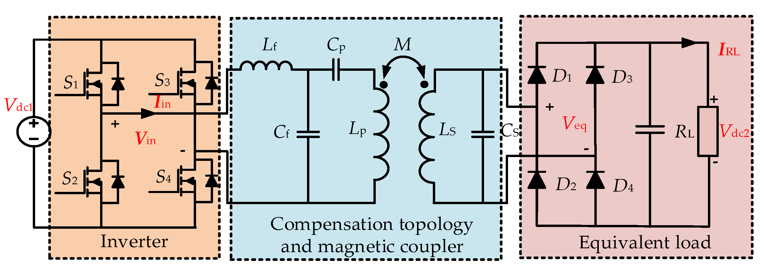
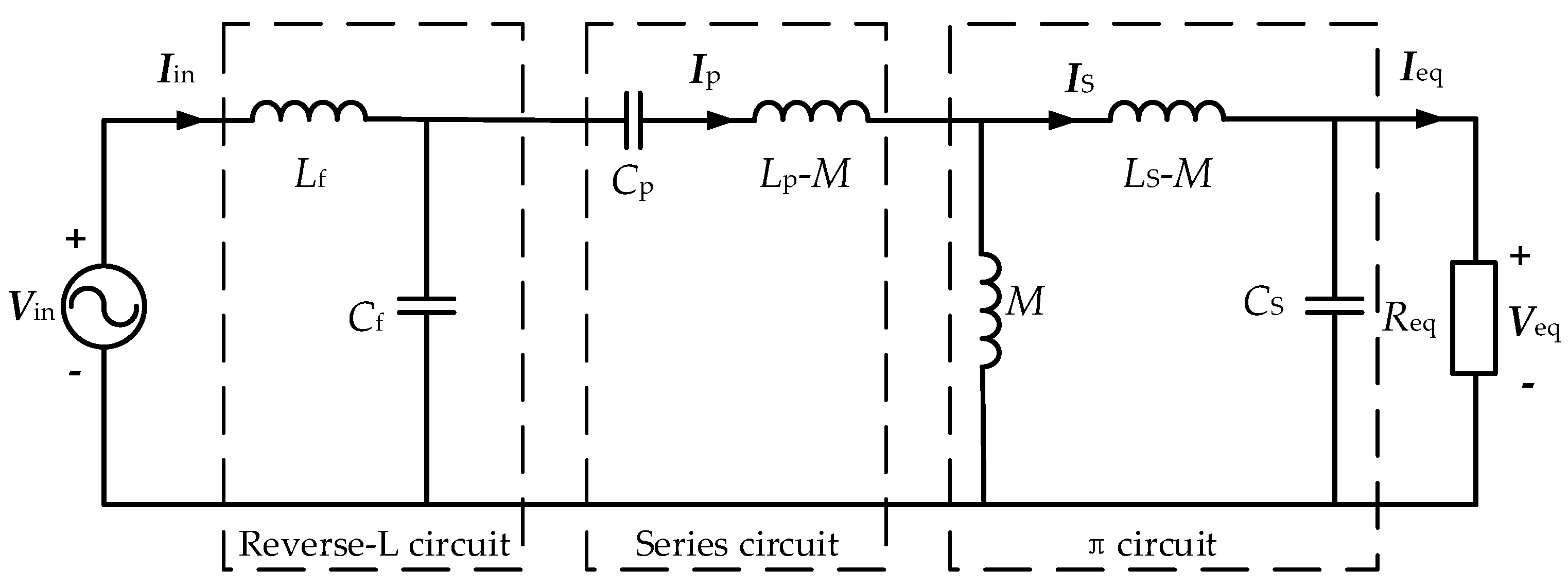
2. Circuit Analysis
3. Parameter Optimization
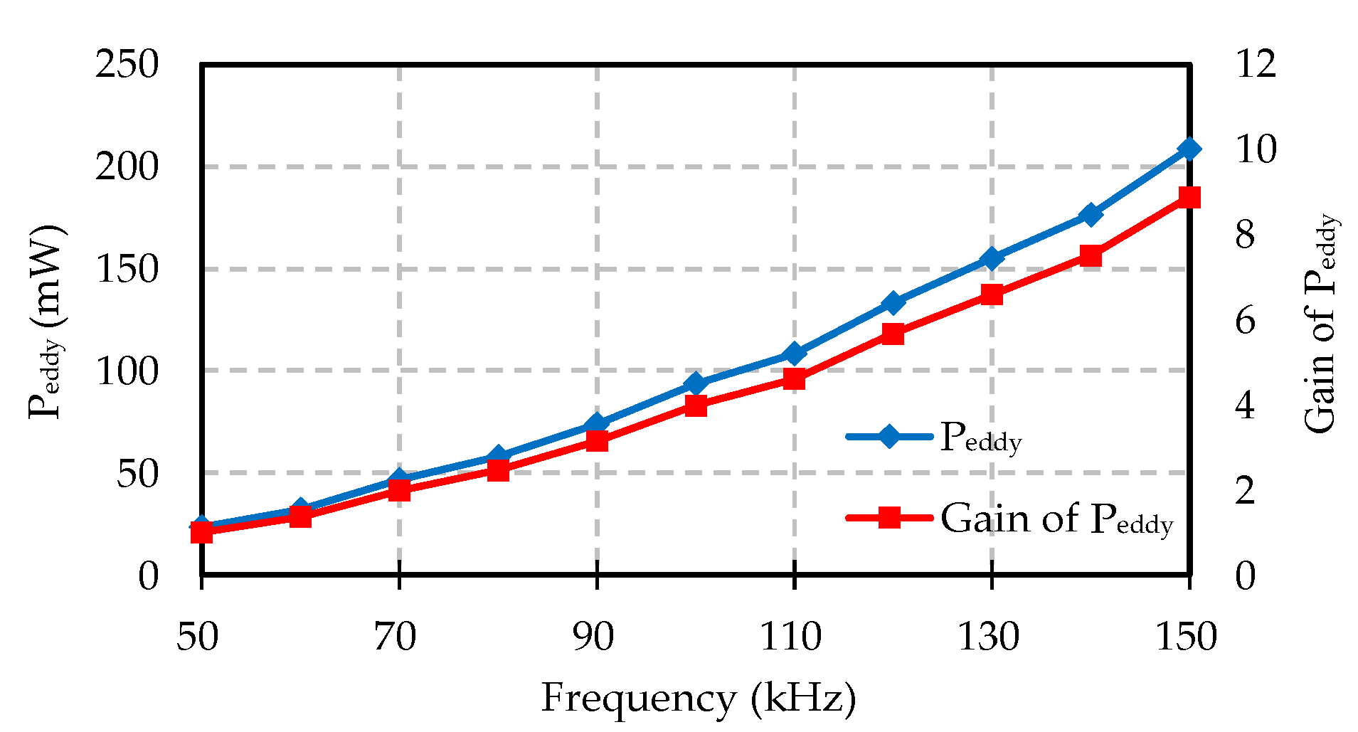
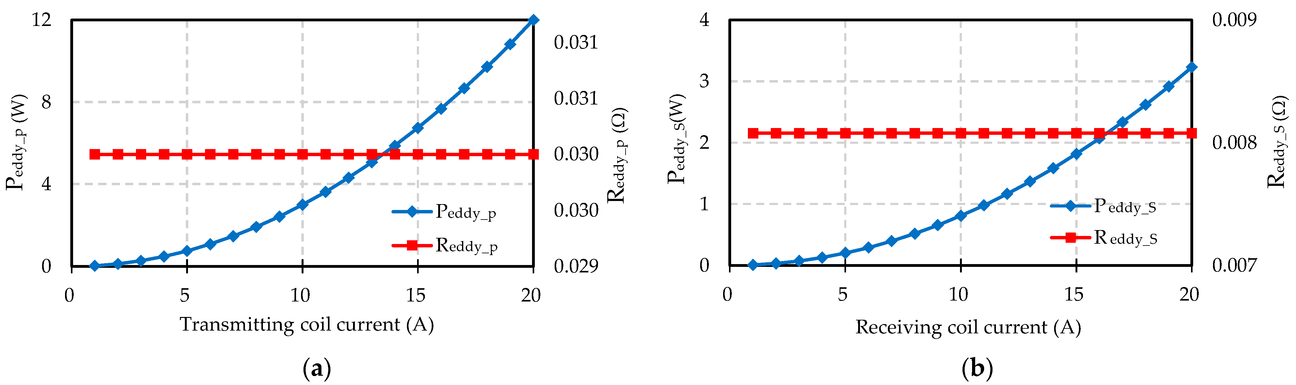
3.1. Eddy Current Loss Analysis
3.2. Objective Function Construction
3.3. Function Solving
3.4. Algorithm Validation
4. Experiments
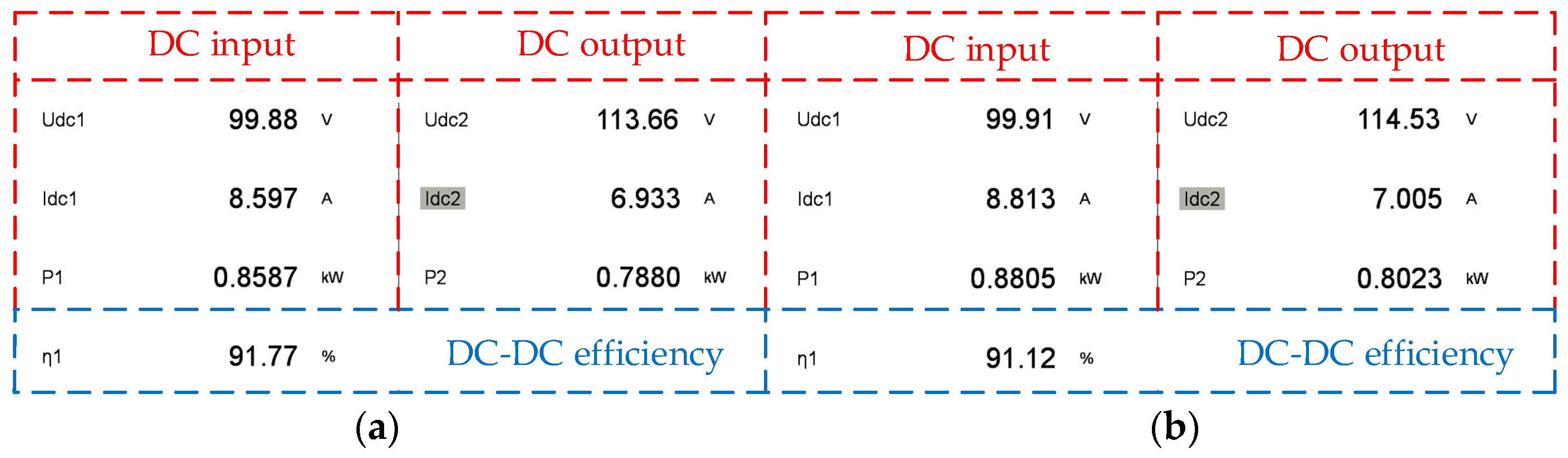
4.1. Seawater Effects
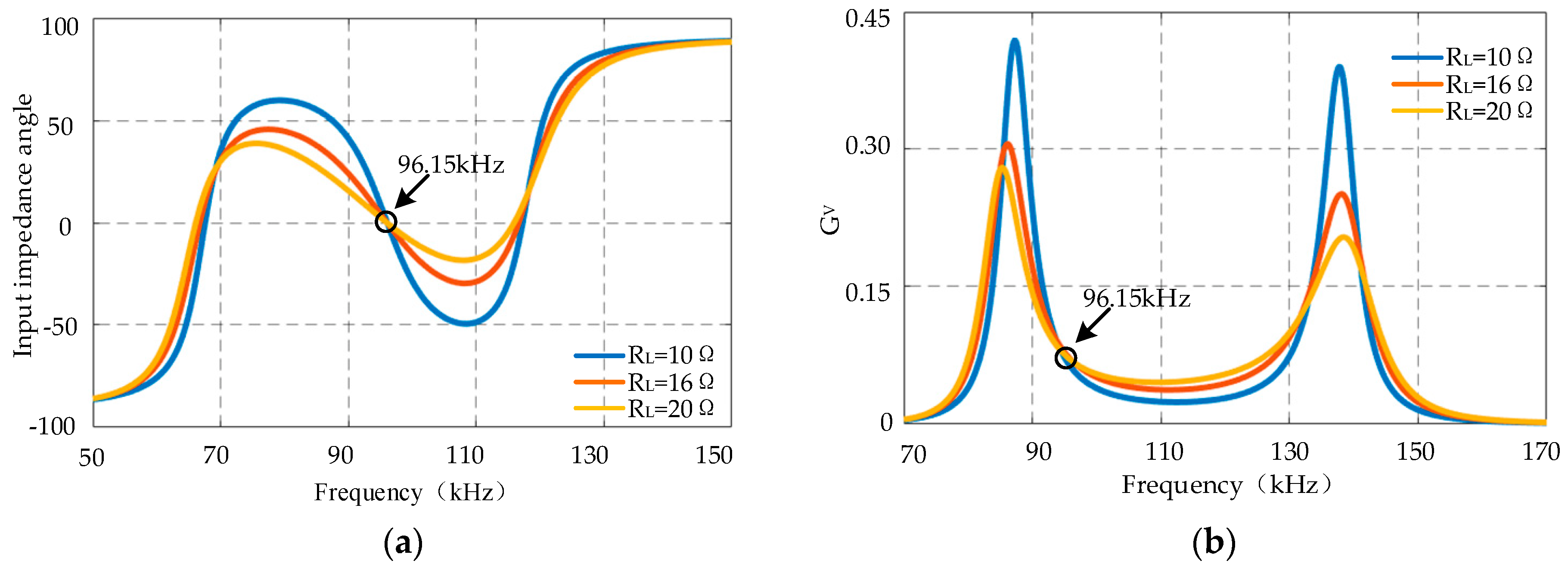
4.2. Analysis of System Output Characteristics
5. Conclusions
Author Contributions
Funding
Acknowledgments
Conflicts of Interest
References
- Zhang, Y.M.; Lu, T.; Zhao, Z.M.; He, F.B.; Chen, K.N.; Yuan, L.Q. Employing Load Coils for Multiple Loads of Resonant Wireless Power Transfer. IEEE Trans. Power Electron. 2015, 30, 6174–6181. [Google Scholar] [CrossRef]
- Zhou, J.; Li, D.; Chen, Y. Frequency Selection of an Inductive Contactless Power Transmission System for Ocean Observing. Ocean Eng. 2013, 60, 175–185. [Google Scholar] [CrossRef]
- Cheng, Z.; Lei, Y.; Song, K.; Zhu, C. Design and Loss Analysis of Loosely Coupled Transformer for an Underwater High-Power Inductive Power Transfer System. IEEE Trans. Magn. 2015, 51, 1–10. [Google Scholar]
- Momeneh, A.; Castilla, M.; Ghahderijani, M.M.; Miret, J.; Vicuna, L.G. Analysis, Design and Implementation of a Residential Inductive Contactless Energy Transfer System with Multiple Mobile Clamps. IET Power Electron. 2017, 10, 875–883. [Google Scholar] [CrossRef] [Green Version]
- Matsumoto, N.H.; Trescases, O. Wireless Electric Vehicle Charger with Electromagnetic Coil-based Position Correction Using Impedance and Resonant Frequency Detection. IEEE Trans. Power Electron. 2020, 35, 7873–7883. [Google Scholar]
- Kojiya, T.; Sato, F.; Matsuki, H.; Sato, T. Automatic Power Supply System to Underwater Vehicles Utilizing Non-contacting Technology. Proc. Oceans MTS/IEEE Techno-Ocean 2004, 4, 2341–2345. [Google Scholar]
- Cai, C.; Wu, S.; Zhang, Z. Development of a Fit-to-surface and Lightweight Magnetic Coupler for Autonomous Underwater Vehicle Wireless Charging Systems. IEEE Trans. Power Electron. 2021, 36, 9927–9940. [Google Scholar] [CrossRef]
- Yan, Z.; Zhang, Y.; Zhang, K. Underwater Wireless Power Transfer System with a Curly Coil Structure for AUVs. IET Power Electron. 2019, 12, 2559–2565. [Google Scholar] [CrossRef] [Green Version]
- Kan, T.; Mai, R.; Mercier, P.P.; Mi, C. A Three-phase Wireless Charging System for Lightweight Autonomous Underwater Vehicles. In Proceedings of the IEEE Applied Power Electronics Conference and Exposition (APEC), Tampa, FL, USA, 26–30 March 2017; pp. 1407–1411. [Google Scholar]
- Villa, J.L.; Sallan, J.; Osorio, J.F.S.; Llombart, A. High-Misalignment Tolerant Compensation Topology For ICPT Systems. IEEE Trans. Ind. Electron. 2012, 59, 945–951. [Google Scholar] [CrossRef]
- Zhang, W.; Mi, C.C. Compensation Topologies of High-Power Wireless Power Transfer Systems. IEEE Trans. Veh. Technol. 2016, 65, 4768–4778. [Google Scholar] [CrossRef]
- Yan, Z.; Zhang, Y.; Song, B. An LCC-P Compensated Wireless Power Transfer System with a Constant Current Output and Reduced Receiver Size. Energies 2019, 12, 172. [Google Scholar] [CrossRef] [Green Version]
- Valtchev, S.; Borges, B.; Brandisky, K.; Klaassens, J.B. Resonant Contactless Energy Transfer with Improved Efficiency. IEEE Trans. Power Electron. 2009, 24, 685–699. [Google Scholar] [CrossRef]
- Hou, J.; Chen, Q.; Wong, S.; Tse, C.K.; Ruan, X. Analysis and Control of Series/Series-Parallel Compensated Resonant Converter for Contactless Power Transfer. IEEE Trans. Emerg. Sel. Topics Power Electron. 2015, 3, 124–136. [Google Scholar]
- Thrimawithana, D.J.; Madawala, U.K. A Generalized Steady-State Model for Bidirectional IPT Systems. IEEE Trans. Power Electron. 2013, 28, 4681–4689. [Google Scholar] [CrossRef]
- Li, S.Q.; Li, W.H.; Deng, J.J.; Nguyen, T.D.; Mi, C.C. A Double-Sided LCC Compensation Network and Its Tuning Method for Wireless Power Transfer. IEEE Trans. Veh. Technol. 2015, 64, 2261–2273. [Google Scholar] [CrossRef]
- Qiao, K.; Sun, P.; Rong, E.; Sun, J.; Zhou, H.; Wu, X. Anti-misalignment and Lightweight Magnetic Coupler with H-shaped Receiver Structure for AUV Wireless Power Transfer. IET Power Electron. 2022, 1–15. [Google Scholar] [CrossRef]
- Lu, J.; Zhu, G.; Lin, D.; Zhang, Y.; Wang, H.; Mi, C.C. Realizing Constant Current and Constant Voltage Outputs and Input Zero Phase Angle of Wireless Power Transfer Systems with Minimum Component Counts. IEEE Trans. Intell. Transp. Syst. 2020, 22, 600–610. [Google Scholar] [CrossRef]
- Wang, D.; Cui, S.; Zhang, J.; Bie, Z.; Song, K.; Zhu, C. A novel arc-shaped lightweight magnetic coupler for AUV wireless power transfer. IEEE Trans. Ind. Appl. 2021, 58, 1315–1329. [Google Scholar] [CrossRef]
- Zhang, K.; Ma, Y.; Yan, Z.; Di, Z.; Song, B.; Hu, A.P. Eddy Current Loss and Detuning Effect of Seawater on Wireless Power Transfer. IEEE Trans. Emerg. Sel. Topics Power Electron. 2018, 8, 909–917. [Google Scholar] [CrossRef]
- Deng, Q.; Liu, J.; Czarkowski, D.; Kazimierczuk, M. Frequency-Dependent resistance of Litz-wire aquare solenoid coils and quality factor optimization for wireless power transfer. IEEE Trans. Ind. Electron. 2016, 63, 2825–2837. [Google Scholar] [CrossRef]
- Holland, J.H. Adaptation in Natural and Artificial Systems; University of Michigan Press: Ann Arbor, MI, USA, 1975. [Google Scholar]
- Yan, Z.; Zhang, Y.; Kan, T.; Lu, F.; Zhang, K.; Song, B.; Mi, C.C. Frequency Optimization of a Loosely Coupled Underwater Wireless Power Transfer System Considering Eddy Current Loss. IEEE Trans. Ind. Electron. 2019, 66, 3468–3476. [Google Scholar] [CrossRef]


| Media | Relative Permittivity | Conductivity (S/m) | Relative Permeability |
|---|---|---|---|
| air | 1.0006 | 0 | 1.000004 |
| freshwater | 81 | 0.01 | 0.999991 |
| seawater | 81 | 4 | 0.999991 |
| Parameter | Symbol | Value |
|---|---|---|
| Transconductance | GV | 0.067 |
| Resistance range | RL | 10–20 Ω |
| Resonant frequency | f0 | 96.15 kHz |
| Transmitter inductance | Lp | 49.84 μH |
| Transmitter-side series compensation capacitance | Cp | 88.23 nF |
| Receiver inductance | LS | 26.28 μH |
| Receiver-side parallel compensation capacitance | CS | 104.18 nF |
| Compensation inductance | Lf | 9 μH |
| Transmitter-side parallel compensation capacitance | Cf | 304.44 nF |
| Note | Symbol | Value (Air) | Value (Seawater) |
|---|---|---|---|
| Resonant frequency | f0 | 96.15 kHz | 96.15 kHz |
| DC input voltage | Vdc1 | 100 V | 100 V |
| Transmitter inductance | Lp | 49.84 μH | 49.26 μH |
| Transmitter resistance | Rp | 90 mΩ | 120 mΩ |
| Transmitter-side series compensation capacitance | Cp | 88.23 nF | 88.23 nF |
| Receiver inductance | LS | 26.28 μH | 26.39μH |
| Receiver resistance | RS | 35 mΩ | 43 mΩ |
| Receiver-side parallel compensation capacitance | CS | 104.18 nF | 104.18 nF |
| Compensation inductance | Lf | 9 μH | 9μH |
| Transmitter-side parallel compensation capacitance | Cf | 304.44 nF | 304.44 nF |
| Coupling coefficient | k | 0.438 | 0.443 |
| Resistance range | RL | 10–20 Ω | 10–20 Ω |
Publisher’s Note: MDPI stays neutral with regard to jurisdictional claims in published maps and institutional affiliations. |
© 2022 by the authors. Licensee MDPI, Basel, Switzerland. This article is an open access article distributed under the terms and conditions of the Creative Commons Attribution (CC BY) license (https://creativecommons.org/licenses/by/4.0/).
Share and Cite
Qiao, K.; Rong, E.; Sun, P.; Zhang, X.; Sun, J. Design of LCC-P Constant Current Topology Parameters for AUV Wireless Power Transfer. Energies 2022, 15, 5249. https://doi.org/10.3390/en15145249
Qiao K, Rong E, Sun P, Zhang X, Sun J. Design of LCC-P Constant Current Topology Parameters for AUV Wireless Power Transfer. Energies. 2022; 15(14):5249. https://doi.org/10.3390/en15145249
Chicago/Turabian StyleQiao, Kangheng, Enguo Rong, Pan Sun, Xiaochen Zhang, and Jun Sun. 2022. "Design of LCC-P Constant Current Topology Parameters for AUV Wireless Power Transfer" Energies 15, no. 14: 5249. https://doi.org/10.3390/en15145249
APA StyleQiao, K., Rong, E., Sun, P., Zhang, X., & Sun, J. (2022). Design of LCC-P Constant Current Topology Parameters for AUV Wireless Power Transfer. Energies, 15(14), 5249. https://doi.org/10.3390/en15145249