Article

Model Predictive Control of a Modular 7-Level Converter Based on SiC-MOSFET Devices—An Experimental Assessment †

Laboratory of Power and Control Systems (LSPyC), Facultad de Ingeniería, Universidad Nacional de Asunción, Luque 2060, Paraguay
*
Author to whom correspondence should be addressed.
This paper is an extended version of our paper published in the World Multiconference on Systemics, Cybernetics and Informatics, vol. 18, no. 5, pp. 57–61, 2020.
Energies 2022, 15(14), 5242; https://doi.org/10.3390/en15145242
Submission received: 30 May 2022 / Revised: 28 June 2022 / Accepted: 4 July 2022 / Published: 20 July 2022
(This article belongs to the Section F3: Power Electronics)

Abstract

:
Power converter technology has expanded into a wide range of low, medium, and high power applications due to the ability to manage electrical energy efficiently. In this regard, the modular multilevel converter has become a viable alternative to ensure an optimal harmonic profile with a sinusoidal voltage at the load side. Model predictive control (MPC) is a state-of-the-art technique that has been successfully used to control power electronic converters due to its ability to handle multiple control objectives. Nevertheless, in the classical MPC approach, the optimal vector is applied during the whole sampling period producing an output voltage. This solution causes an unbalanced switching frequency of the power semiconductor, which then causes unbalanced stress on the power devices. Modulation strategies have been combined with MPC to overcome these shortcomings. This paper introduces the experimental assessment of a 7-level converter combining a simple phase shift multicarrier pulse-width modulation approach with the MPC technique. A custom test-bed based on SiC-MOSFETs switches is used to validate the proposal.

1. Introduction

Power converter technologies play an increasingly important role in many applications mainly due to their ability to efficiently manage electrical energy [1]. In this regard, the high penetration of power electronic converters has been justified primarily because of the growth of the electricity generated by renewable energies such as solar and wind [2]. Since all power converters connected to the grid must fulfill the grid codes, power quality has recently become one of the main issues to solve [3,4]. A power quality problem can be seen as the divergence of magnitude and frequency from the ideal sinusoidal waveform [5,6]. This divergence typically impacts currents and voltage at the grid side; the load side has been proposed in several papers to address the power quality issues at the load side [7,8]. The dizzying advance of power converters has been enhanced by developing high-performance microprocessors capable of implementing complex nonlinear digital controllers. The field of power electronic semiconductors has recently developed new high-speed switching devices with tremendous low on-state loss. One of the most promising power electronic semiconductors is the SiC-MOSFET used in this paper. As a result, new power electronic converters can be smaller than the classical ones [9].
Conventional two-level voltage source converters (2L-VSCs) are still one of the most used converters for many applications, and, as all VSCs, they are considered the fundamental component in the conversion energy system. However, the reduced number of levels of 2L-VSCs cause loss problems and poor power quality due to their bad harmonic profile [10,11]. To solve this issue, the modular multilevel converter (MMC) has drawn the attention of both industry and academic sectors due to its capability to generate sinusoidal voltages and currents with a low content of harmonic distortions at the load side. Among these MMC topologies, the cascade H-Bridge (CHB) is a popular choice because of its modularity, which simplifies the extension for a higher number of levels of the MMC. Moreover, the MMC does not demand a vast number of flying capacitors or clamping diodes [12]. Consequently, the CHB-based MMC is currently a competitive choice in the new era of VSCs [13].
Commonly the CHB-based MMC uses IGBT as switching. Nevertheless, the SiC-MOSFET has been used as an alternative mainly because it can reach higher switching frequencies than IGBT devices [14,15]. Yet, it is not enough to incorporate faster switching to the MMC to improve the power quality [16,17]. Instead, it is essential to manage this problem with a suitable controller. In this regard, model predictive control (MPC) has been successfully used to control VSCs due to its ability to handle multiple control goals and constraints, straightforward implementation, and quick transient response [18,19]. However, the MPC scheme operates with variable frequency leading to a spread switching spectrum [20]. To eliminate the variable switching frequency behavior of the classical MPC, this article introduces a fixed switching frequency MPC (FSF-MPC) based on a phase shift multicarrier pulse-width modulation (PSM-PWM) approach [21,22] and the experimental assessment of the CHB-based MMC [23].
This article is divided as follows. Section 2 introduces the mathematical model of the CHB-based MMC topology. Then, in Section 3, the MMC’s predictive model is derived, and the proposed MPC strategy is presented. In Section 4, some figures of merits are used as a reference to analyze the obtained experimental results. Finally, the main conclusions of this work are given in the last section.

2. Proposed 7-Level MMC Topology

Figure 1 shows the proposed MMC scheme. Each MMC has four SiC-MOSFETs and is fed by an independent dc-link. To obtain the 7-level MMC, connecting in a series of three cells is necessary for each phase. S x y ϕ represent the firing signals, with being ϕ the phase a, b, or c, while x is the cell number in each phase and y the switching device in each cell ( y = 1, 2, 3, or 4). Some firing signal combinations are shown in Table 1 for phase “a”. The firing signals for phases b and c can be obtained likewise, taking into account the permitted combinations and avoiding short circuits [24,25].
Figure 2 depicts the proposed FSF-MPC control that uses the explicit MMC’s mathematical model to compute the predictive behavior of the control actions for every switching state. It is essential to highlight that the 7-level CHB-based MMC is tied to the load through an R L filter. Kirchhoff’s circuit laws can be used to obtain the system’s dynamic. The following equation is the state-space representation obtained using Kirchhoff’s rules on the AC side.
i c a t . i c b t . i c c t . = F i c a t i c b t i c c t + G v c a t v c b t v c c t ,
where
F = R f L f 0 0 0 R f L f 0 0 0 R f L f , G = 1 L f 0 0 0 1 L f 0 0 0 1 L f .
L f represents the inductive filter, which has a parasitic resistance ( R f ) that is connected between the point of common coupling (PCC) and the MMC’s output.

3. MMC Predictive Model

A forward-Euler discretization procedure has been used to reduce the computational burden of the FSF-MPC. Then, the predictive model can be obtained from (1), with the following equation as the MMC discrete-time model [26,27].
i ^ c a k + 1 i ^ c b k + 1 i ^ c c k + 1 = A i c a k i c b k i c c k + B v c a k v c b k v c c k ,
where
A = a 1 0 0 0 a 1 0 0 0 a 1 , B = T s L f 0 0 0 T s L f 0 0 0 T s L f ,
with a 1 = 1 R f T s L f and T s as the sampling time.

3.1. Current Reference Generation

The FSF-MPC technique requires the previous calculation of the reference currents to calculate the cost function in (8). Therefore, firstly, we must select the active and reactive power reference P L * and Q L * to be applied to the load side, considering that the voltage references v s c ϕ are the maximum voltages of the fundamental frequency at the output of the multilevel converter. Using the Clarke transformation matrix ( T ), the currents and voltages can be represented in static reference frame α β as:
v s c α v s c β = 2 3 1 1 2 1 2 0 3 2 3 2 1 2 1 2 1 2 T v s c a v s c b v s c c .
Then, the relationship between the active and reactive power, as a function of the current references in α β subspace can be represented by:
i c α * i c β * = 1 ( v s c α ) 2 + ( v s c β ) 2 v s c α v s c β v s c β v s c α P L * Q L * .
The phase current references used in the optimization process are:
i c a * i c b * i c c * = 2 3 1 1 2 1 2 0 3 2 3 2 1 2 1 2 1 2 1 T 1 i c α * i c β * 0 .

3.2. Cost Function and Optimization Process

The proposed fixed switching frequency controller is based on the MPC approach and makes explicit use of an optimization process to minimize a definite cost function, represented by (8). The cost function evaluates the current tracking error in each sampling period using the prediction model and considers all possible firing signal combinations.
g a = i c a * i ^ c a k + 1 2 , g b = i c b * i ^ c b k + 1 2 , g c = i c c * i ^ c c k + 1 2 .
Considering n c = 3 cells per phase connected in cascade, we need 2 n c = 6 firing signals to control the output voltages ( v c ϕ ). This produces sixty-four ( ε = 2 2 n c = 64 ) firing signals to be evaluated in the optimization process. After evaluating the cost function for all possible combinations of firing signals, the optimization algorithm selects the optimum vector S η , o p t ϕ for each firing signal of each cell and applies the optimal vector during a sampling period. The optimization process can be summariszed in the pseudocode represented in Algorithm 1.
Algorithm 1 Pseudocode of the optimization process applied to the FSF-MPC current controller
1. Initialize g o p t a : = , g o p t b : = , g o p t c : = , η : = 0
2. Compute the current references (7).
3. while  η ε  do
4.      S η ϕ S x y ϕ x & y = 1 , 2 , 3
5.      Calculate the prediction currents (3).
6.      Compute the cost function, (8).
7.      if  g a < g o p t a  then
8.         g o p t a g a , S o p t a S η a
9.    end if
10.     if  g b < g o p t b  then
11.         g o p t b g b , S o p t b S η b
12.     end if
13.     if  g c < g o p t c  then
14.         g o p t c g c , S o p t c S η c
15.     end if
16.     η : = η + 1
17. end while
18. Compute the modulation signals (9).
19. Get the turn-on times of the firing signals according to Figure 3.
20. Apply the firing signals.
Figure 3. The PSM-PWM scheme for the CHB-based MMC phase ϕ .
Energies 15 05242 g003

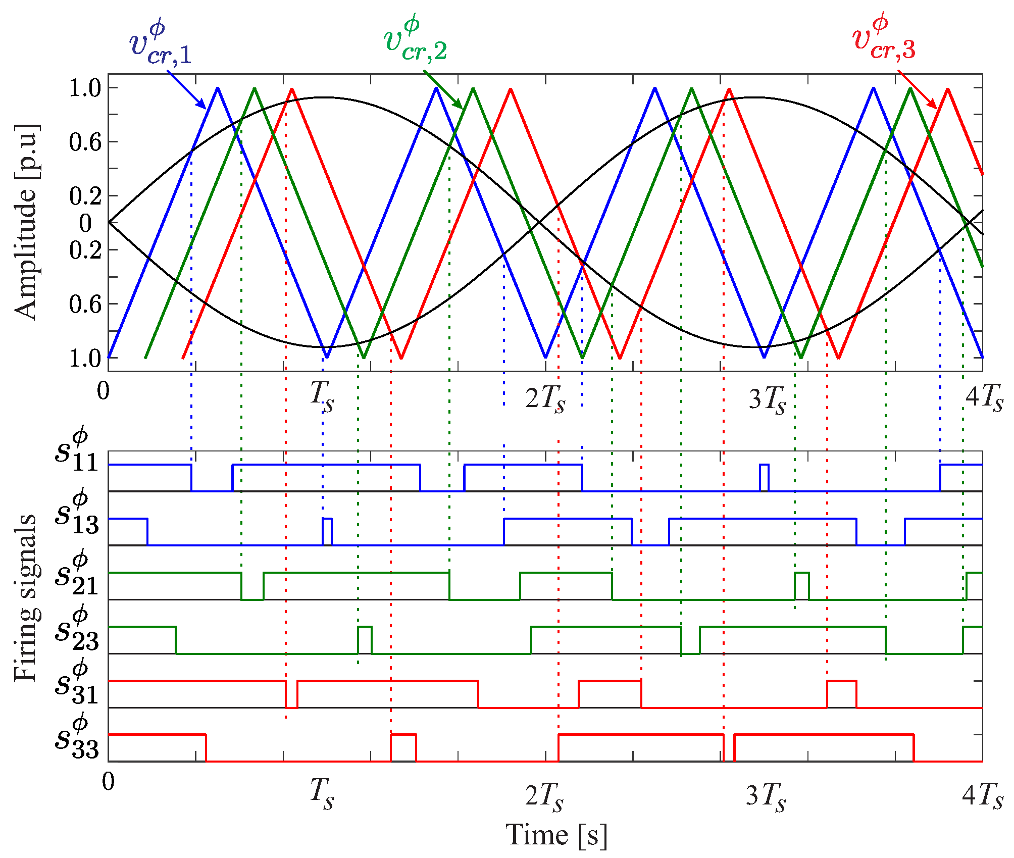
3.3. Proposed PSM-PWM Strategy

The classical model-based predictive control, after selecting the optimal vector S η , o p t ϕ , is applied during the whole sampling period producing a output voltage v c , η , o p t ϕ . This solution produces an unbalanced switching frequency, causing, in turn, unbalanced stress on the power devices.
The proposed controller uses a modulation stage based on a phase shift multicarrier pulse-width modulation approach. A triangular three phase-shifted carrier signal with the same frequency and magnitude are needed to obtain the turn-on times of the firing signals of each cell using the proposed PSM-PWM strategy. The two adjacent carrier signals are shifted by 180 /3. By comparing one specific carrier signal v c r , i ϕ with a pair of inverted sinusoidal modulation signals, we obtain the firing signals of s x 1 ϕ and s x 3 ϕ , as shown in Figure 3. Note that the carrier frequency and the sampling frequency are the same, and the modulation signals are associated with the optimal phase voltages and are normalized between −1 and 1, that is:
v c o n t ϕ = v c , η , o p t ϕ 3 v d c .

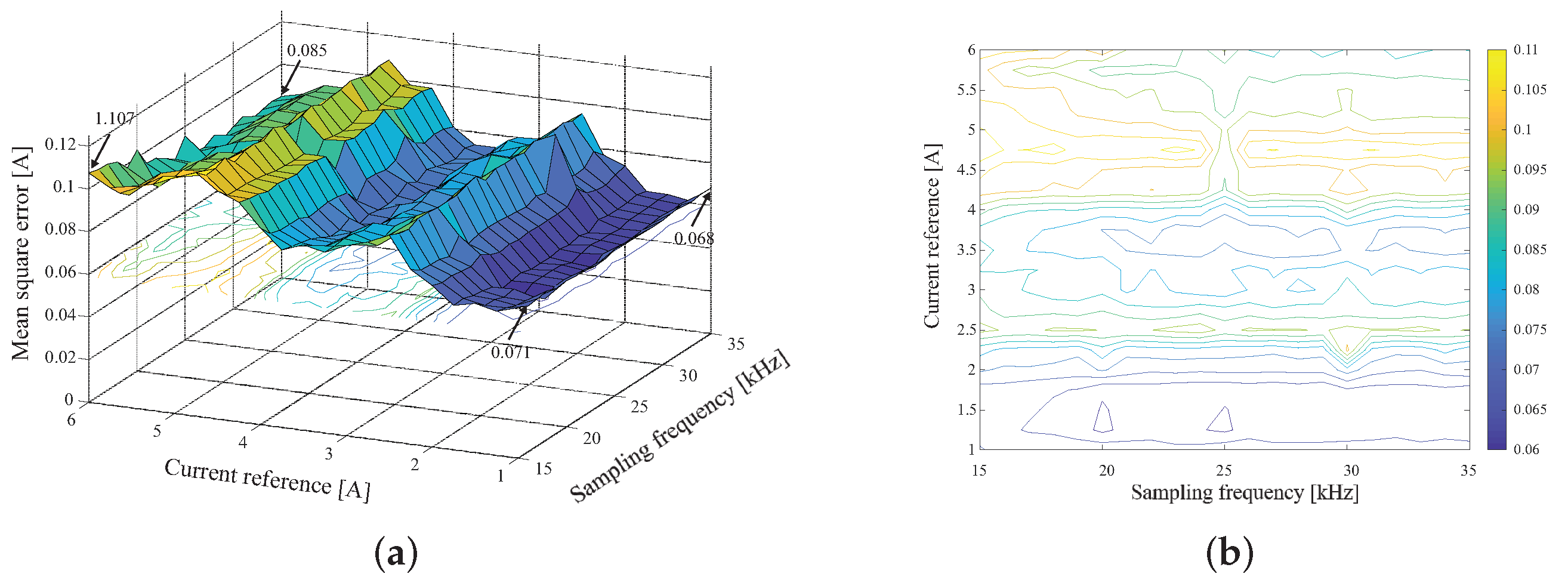
3.4. Theoretical Results

A parametric analysis was performed to evaluate the performance of the proposed controller. For that purpose, different sampling frequencies (from 15 kHz to 35 kHz in 1 kHz steps) and current amplitude references (from 1 A to 6 A in 0.5 A steps) were considered. The performance of the proposed controller was analyzed in steady-state operation, considering the mean square error phase current i c a tracking as a figure of merit. Figure 4a shows the parametric MSE evolution, where it is observed that at low reference current amplitudes, the mean square error levels remained practically invariant as a function of the sampling frequency variation (from 0.071 A for 15 kHZ to 0.068 A for 35 kHz). However, as the reference current became higher, the efficiency of the controller in terms of the lower root mean square error improved. For the particular case of i c a = 6 A, the MSE was reduced from 1.107 A (for 15 kHz) to 0.085 A (for 35 kHz of sampling frequency). Figure 4b summarizes in a level curve the different MSE values obtained in the parametric analysis.

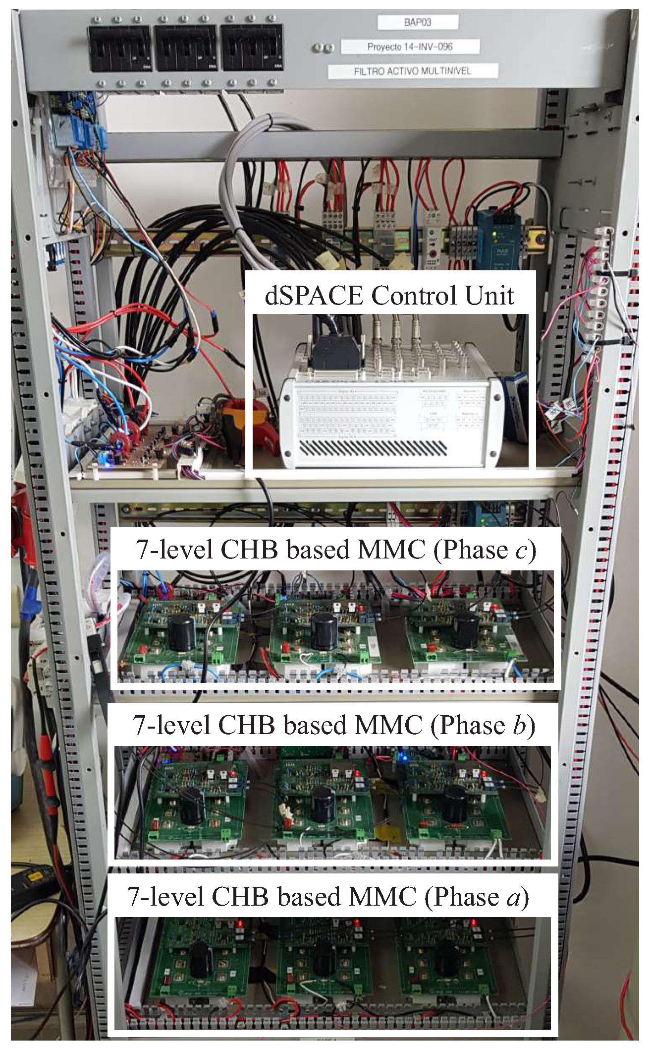
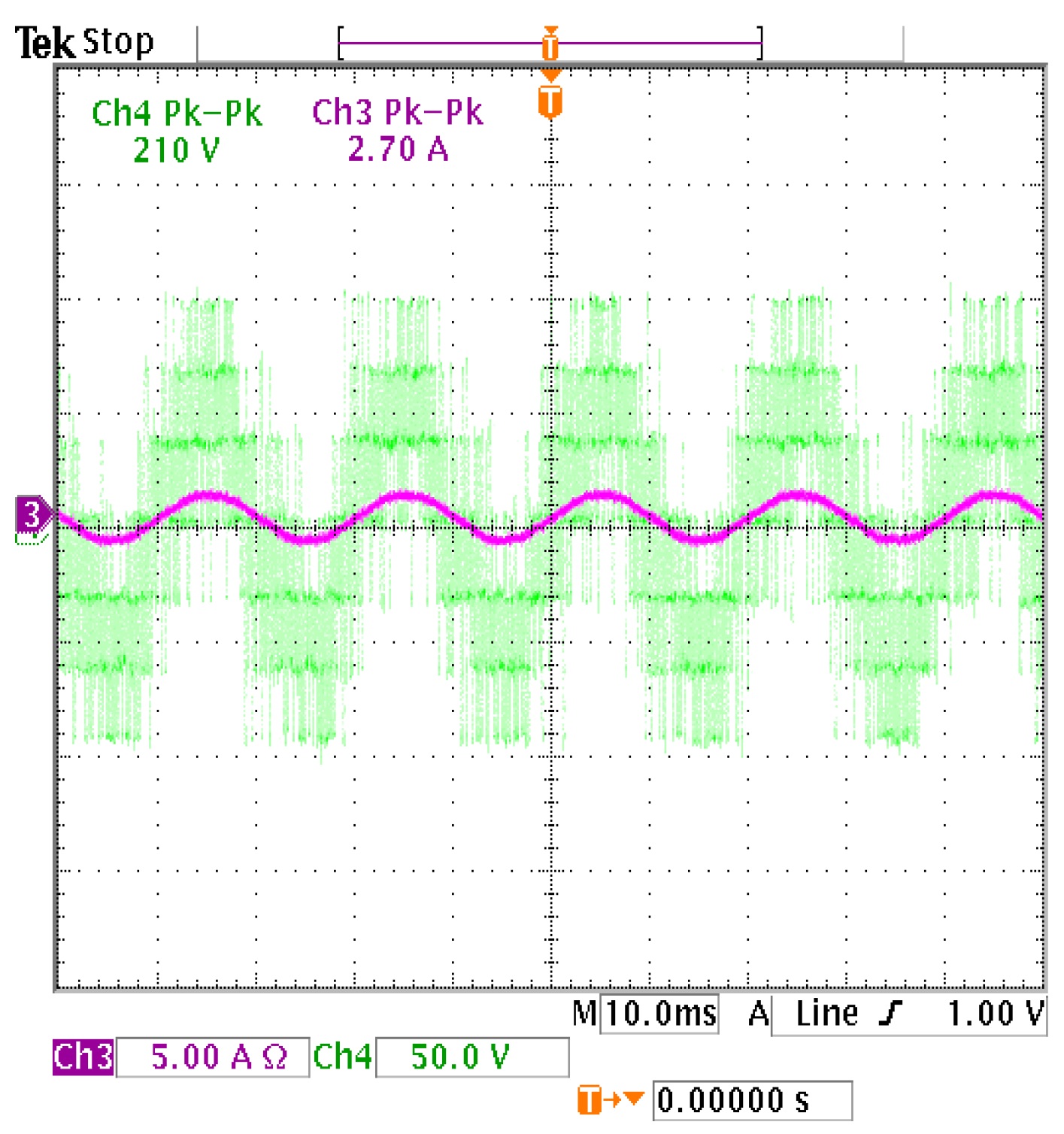
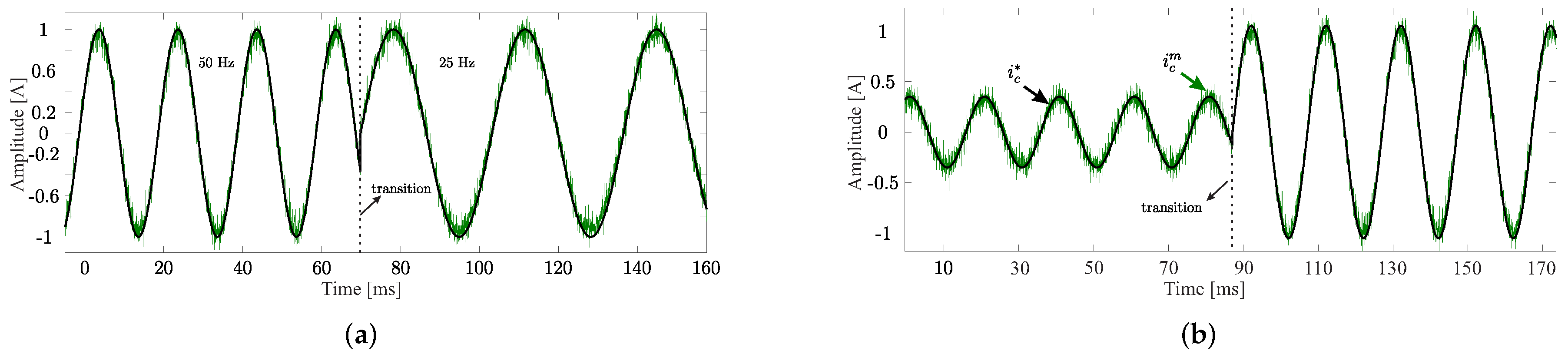
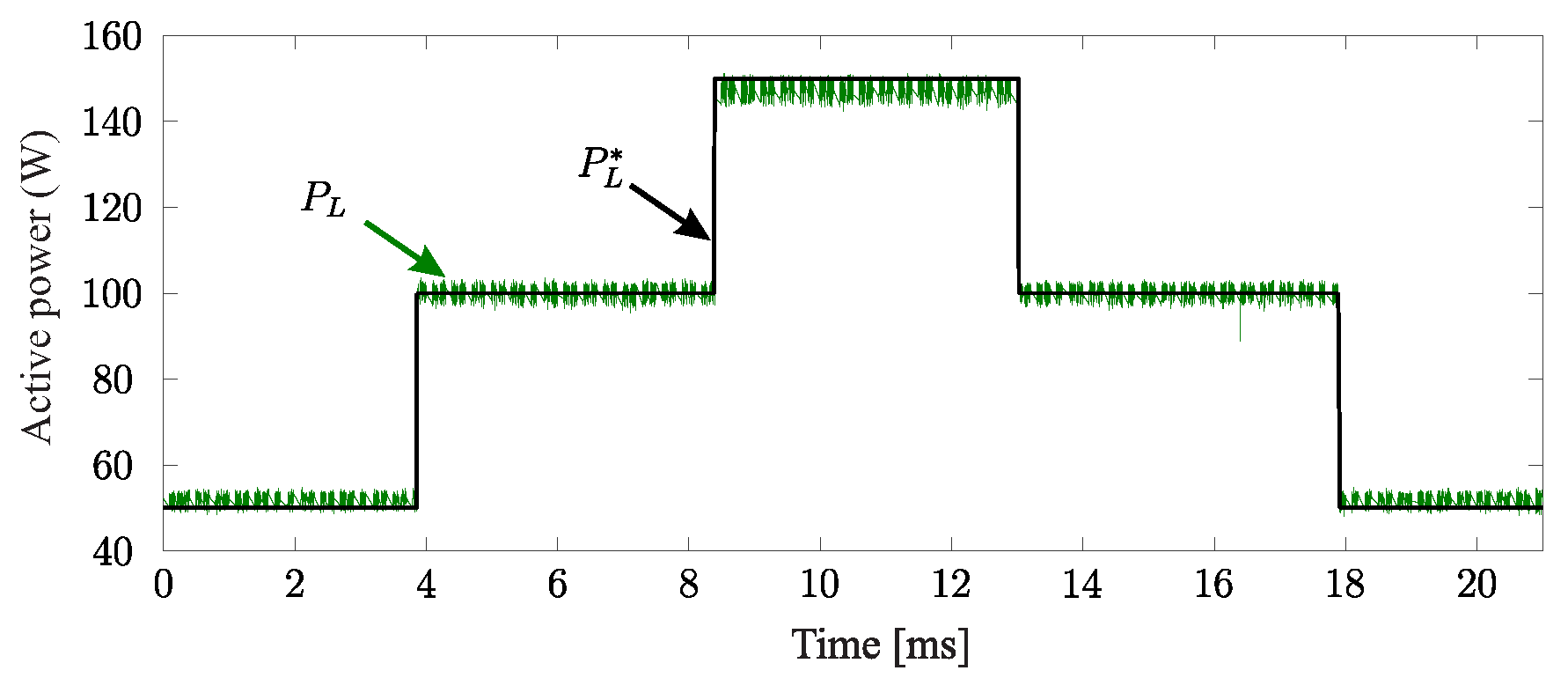
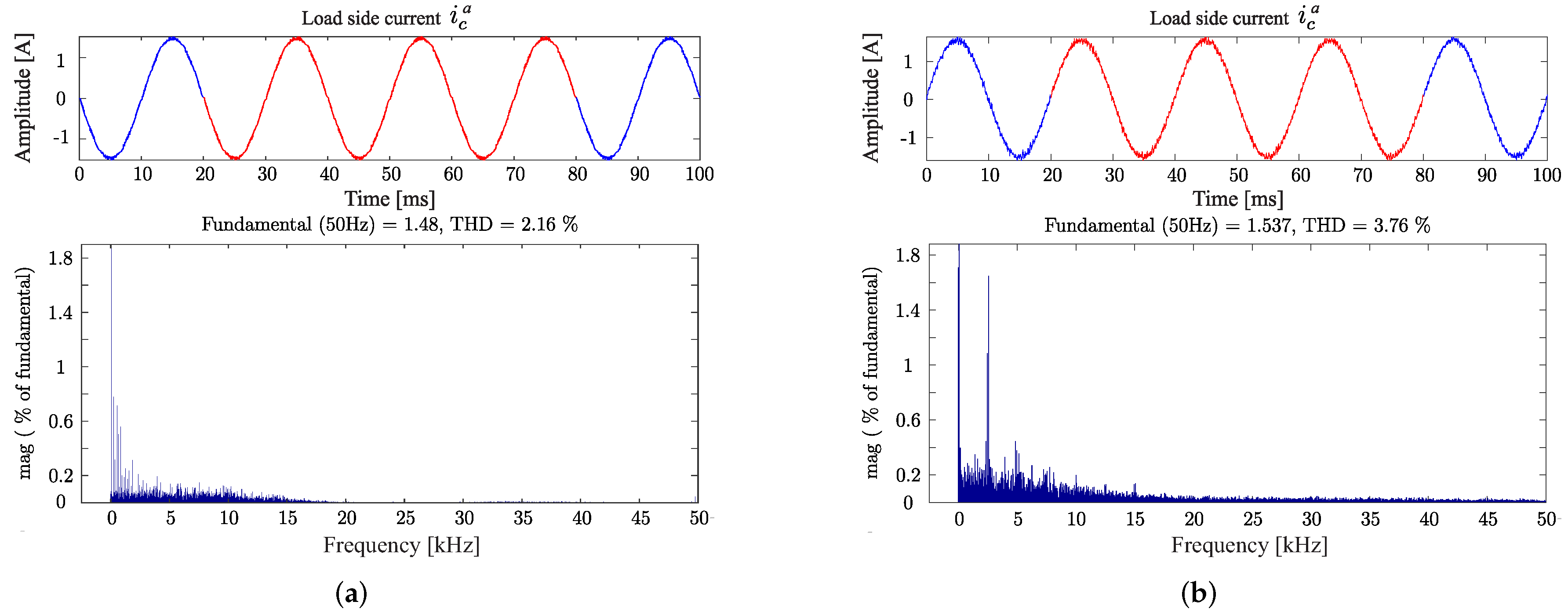
4. Experimental Assessment

The proposed 7-level CHB-based MMC was validated through experimental results obtained by using a custom test bench, as shown in Figure 5. This converter was implemented using three cells per phase arranged in a cascade scheme. Each cell integrated four SiC-MOSFET semiconductor devices and was fed with an independent dc-link voltage. The dc-link voltages were implemented using independent linear dc sources, which ensured the balance in the dc-link level voltages of the multilevel converter. The 7-level converter was controlled by a real-time platform based on dSPACE MicroLabBox programmed using a MATLAB/Simulink environment considering a T s = 25   μ s sampling time. The frequency at the grid side was 50 Hz, and the voltage was set to 310.2 V. The rest of the electrical parameters used for the controller were v dc = 33 V, R f = 0.09   Ω , L f = 3 mH, R L = 23.2   Ω , and L L = 55 mH. The active power and current tracking measurements were performed with analogue meters and were used as a figure of merit to validate the proposed control strategy.
Initially, the 7-level CHB-based MMC was analyzed in an open-loop configuration. Figure 6 shows the 7 levels of the output voltage ( v c a ) and the load current ( i L a ) evolution at the output of the multilevel converter. Then, the FSF-MPC controller was evaluated in a closed-loop to analyze the current control’s performance at the load side under transient conditions. Figure 7a shows the current tracking evolution when a reference amplitude changed from 0.5 A to 1 A. The result showed excellent and fast-tracking of its reference.
Then, the system’s dynamic response was verified by measuring the output response when having a variation in the frequency of reference current from 50 Hz to 25 Hz. It can be verified from Figure 7b that the current had the amplitude and frequency specified by the reference current, which shows the proper operation of the 7-level CHB-based MMC and the implemented current control. The mean square error (MSE) was around 0.08 A in both cases. Similar results were observed for phases b and c and are not been included for conciseness. On the other hand, the 7-level CHB-based MMC was evaluated from the point of view of active power control at the load side. In this test, a multi-step active power reference ( P L * ) was defined considering Q L * = 0 VAr. Figure 8 shows the results of the reactive power tracking. As shown, the active power applied to the load followed its reference. Finally, Figure 9a shows the simulation results of the load current total harmonic distortion (THD) profile. As observed from the results, the proposed controller provided low ripples as well as a good harmonics profile at the load current side (around 2.16%). The theoretical results are consistent with the harmonic profile obtained experimentally. According to Figure 9b, the experimental load side current THD was around 3.76 %. Note that an analytical comparison of the proposed control technique against other state-of-the-art methods will be not discussed in this paper and is beyond the scope of the article.

5. Conclusions

The paper described the implementation of a 7-level CHB-based MMC and implemented a model-based predictive control strategy. The feasibility and effectiveness of the overall system were investigated and validated through experimental results under steady-state and transient conditions. The controller used a phase shift multicarrier pulse-width modulation strategy. Among the advantages of the proposed FSF-MPC control strategy are: (a) the better harmonic profile of the load phase currents minimizing the total harmonic distortions at the load side; (b) good dynamics performance in terms of the MSE in the tracking reference currents. It can be noted that due to the simple nature of the implemented controller, it could be performed in any industrial application of a wide range of power.

Author Contributions

Conceptualization, R.G., J.P., A.R., L.C. and J.R.; methodology, R.G. and J.P. software, A.R. and L.C.; validation, R.G., J.P. and A.R.; formal analysis, R.G., J.P., A.R., L.C. and J.R.; investigation, R.G., J.P., A.R., L.C. and J.R.; resources, R.G., J.P., A.R., L.C., and J.R.; data curation, R.G., J.P., A.R., L.C. and J.R.; writing—original draft preparation, R.G. and J.P.; writing—review and editing, R.G., A.R. and J.R.; visualization, R.G. and J.P.; project administration, R.G. and J.R.; funding acquisition, R.G. and J.R. All authors have read and agreed to the published version of the manuscript.

Funding

This research was funded through the Consejo Nacional de Ciencia y Tecnología (CONACYT)-Paraguay, Grant Number POSG16-05 and Grant 14-INV-096.

Conflicts of Interest

The authors declare no conflict of interest.

Abbreviations

The following abbreviations have been employed in this work:
ACAlternating current
CHBCascade H-Bridge
FSFFixed switching frequency
IGBTIsolated Gate Bipolar Transistors
MMCModular multilevel converter
MOSFETMetal-Oxide-Semiconductor Field-Effect Transistor
MPCModel-based predictive control
PCCPoint of common coupling
PSM-PWMPhase shift multicarrier PWM
PWMPulse-width modulation
SiCSilicon Carbide
THDTotal harmonic distortion
VSCsVoltage source converters

Nomenclature

C dc dc-link capacitor
g a , g b , g c FSF-MPC cost functions
i L a , i L b , i L c Load phase currents
i c a , i c b , i c c Converter phase currents
i ^ c a ( k + 1 ) , i ^ c b ( k + 1 ) , i ^ c c ( k + 1 ) Converter phase current predictions
i c α , i c β MMC currents in the α β subspace
i c a * , i c b * , i c c * Converter phase current references
v c a , v c b , v c c Converter phase voltages
n c Number of cells
P c * Instantaneous active power reference
Q c * Instantaneous reactive power reference
Q L Instantaneous reactive load power
T Clarke’s transformation matrix
xCorresponding cell number
ySwitching device in each cell
T s Sampling time
v dc dc-link voltage
R f Filter resistance
L f Filter inductance
S η , o p t ϕ Optimum vector
v c , η , o p t ϕ Optimal voltage
v c r , x ϕ Carrier wave
v c o n t ϕ Modulation signals

References

  1. Murillo-Yarce, D.; Rivera, M.; Restrepo, C.; Rodríguez, R.; Wheeler, P.W.; Zanchetta, P.; Mirzaeva, G. Sequential Predictive Current Control of a VSI with Common-Mode Voltage Reduction. In Proceedings of the 10th International Conference on Power Electronics, Machines and Drives (PEMD), Virtual/Online, 15–17 December 2020. [Google Scholar]
  2. Milev, K.; Yaramasu, V.; Dekka, A.; Kouro, S. Predictive control of multichannel boost converter and VSI-based six-phase PMSG wind energy systems with fixed switching frequency. In Proceedings of the 11th Power Electronics, Drive Systems, and Technologies Conference (PEDSTC), Tehran, Iran, 4–6 February 2020; pp. 1–6. [Google Scholar]
  3. Abdelaziz, F.; Azzouz, Z.e.; Omari, A. Common mode voltage mitigation using a new modified model predictive control (mmpc) in a three phase voltage source inverter. In Proceedings of the 6th IEEE International Energy Conference (ENERGYCon), Tunis, Tunisia, 28 September–1 October 2020; pp. 93–97. [Google Scholar]
  4. Gil-González, W.; Escobar-Mejía, A.; Montoya-Giraldo, O. Model Predictive Direct Power Control Applied to Grid-Connected Voltage Source Inverters. In Proceedings of the 11th International Symposium on Power Electronics for Distributed Generation Systems (PEDG), Kiel, Germany, 26–29 June 2020; pp. 610–614. [Google Scholar]
  5. Xu, J.; Soeiro, T.B.; Gao, F.; Chen, L.; Tang, H.; Bauer, P.; Dragičević, T. Carrier-based modulated model predictive control strategy for three-phase two-level VSIs. Trans. Energy Convers. 2021, 36, 1673–1687. [Google Scholar] [CrossRef]
  6. Rojas, D.; Rivera, M.; Toledo, S.; Wheeler, P. Predictive control techniques applied to a 2L-VSI. In Proceedings of the IEEE CHILEAN Conference on Electrical, Electronics Engineering, Information and Communication Technologies (CHILECON), Virtual, 6–9 December 2021; pp. 1–6. [Google Scholar]
  7. Rojas, D.; Rivera, M.; Muñoz, J.; Wheeler, P. Cascaded predictive control for a three-phase VSI with different cost functions. In Proceedings of the IEEE CHILEAN Conference on Electrical, Electronics Engineering, Information and Communication Technologies (CHILECON), Virtual, 6–9 December 2021; pp. 1–6. [Google Scholar]
  8. Xu, J.; Gao, F.; Soeiro, T.B.; Chen, L.; Tarisciotti, L.; Tang, H.; Bauer, P. Model Predictive Control for the Reduction of DC-link Current Ripple in Two-level Three-phase Voltage Source Inverters. In Proceedings of the 22nd European Conference on Power Electronics and Applications (EPE’20 ECCE Europe), Virtual, 7–11 September 2020; p. P-1. [Google Scholar]
  9. Dabkara, M.; Gupta, Y.; Sharma, N.; Sharma, A. A Solar PV Standalone System with Predictive Current Controlled Voltage Source Inverter. In Proceedings of the 3rd International Conference on Emerging Technologies in Computer Engineering: Machine Learning and Internet of Things (ICETCE), Jaipur, India, 7–8 February 2020; pp. 1–6. [Google Scholar]
  10. Comparatore, L.; Renault, A.; Pacher, J.; Rodas, J.; Gregor, R. Finite Control Set Model Predictive Control Strategies for a Three-Phase Seven-level Cascade H-Bridge DSTATCOM. In Proceedings of the 7th International Conference on Renewable Energy Research and Applications (ICRERA), Istanbul, Turkey, 18–21 September 2018; pp. 779–784. [Google Scholar]
  11. Xu, Z.; Liu, Y.; Cao, B.; Liu, B.; Li, S. Research and Application of Compensation Characteristics of DSTATCOM under Unbalanced Load. In Proceedings of the 3rd Advanced Information Technology, Electronic and Automation Control Conference (IAEAC), Chongqing, China, 12–14 October 2018; pp. 806–810. [Google Scholar]
  12. Renault, A.; Rodas, J.; Comparatore, L.; Pacher, J.; Gregor, R. Modulated Predictive Current Control Technique for a Three-Phase Four-Wire Active Power Filter based on H-bridge Two-Level Converter. In Proceedings of the 53rd International Universities Power Engineering Conference (UPEC), Glasgow, UK, 4–7 September 2018; pp. 1–6. [Google Scholar]
  13. Kehl, Z.; Glasberger, T.; Peroutka, Z. Finite Control Set Model Predictive Control of Static Compensator. In Proceedings of the 28th International Symposium on Industrial Electronics (ISIE), Vancouver, BC, Canada, 12–14 June 2019; pp. 858–863. [Google Scholar]
  14. Renault, A.; Ayala, M.; Comparatore, L.; Pacher, J.; Gregor, R. Comparative Study of Predictive-Fixed Switching Techniques for a Cascaded H-Bridge Two level STATCOM. In Proceedings of the 53rd International Universities Power Engineering Conference (UPEC), Glasgow, UK, 4–7 September 2018; pp. 1–6. [Google Scholar]
  15. Pacher, J.; Rodas, J.; Gregor, R.; Rivera, M.; Renault, A.; Comparatore, L. Efficiency analysis of a modular H-bridge based on SiC MOSFET. Taylor Francis Trans. 2019, 7, 59–67. [Google Scholar] [CrossRef]
  16. Ipoum-Ngome, P.G.; Mon-Nzongo, D.L.; Flesch, R.C.C.; Song-Manguelle, J.; Wang, M.; Jin, T. Model-free predictive current control for multilevel voltage source inverters. Trans. Ind. Electron. 2020, 68, 9984–9997. [Google Scholar] [CrossRef]
  17. Vu, H.C.; Lee, H.H. Model-Predictive Current Control Scheme for Seven-Phase Voltage-Source Inverter With Reduced Common-Mode Voltage and Current Harmonics. IEEE J. Emerg. Sel. Top. Power Electron. 2020, 9, 3610–3621. [Google Scholar] [CrossRef]
  18. Rodriguez, J.; Garcia, C.; Mora, A.; Flores-Bahamonde, F.; Acuna, P.; Novak, M.; Zhang, Y.; Tarisciotti, L.; Davari, S.A.; Zhang, Z.; et al. Latest Advances of Model Predictive Control in Electrical Drives—Part I: Basic Concepts and Advanced Strategies. IEEE Trans. Power Electron. 2022, 37, 3927–3942. [Google Scholar] [CrossRef]
  19. Rodriguez, J.; Garcia, C.; Mora, A.; Davari, S.A.; Rodas, J.; Valencia, D.F.; Elmorshedy, M.; Wang, F.; Zuo, K.; Tarisciotti, L.; et al. Latest Advances of Model Predictive Control in Electrical Drives—Part II: Applications and Benchmarking With Classical Control Methods. IEEE Trans. Power Electron. 2022, 37, 5047–5061. [Google Scholar] [CrossRef]
  20. Milev, K.; Yaramasu, V.; Dekka, A.; Kouro, S.; Dragicevic, T.; Rodriguez, J. Modulated Model Predictive Torque and Power Control of Gearless PMSG Wind Turbines. In Proceedings of the 11th International Symposium on Power Electronics for Distributed Generation Systems (PEDG), Dubrovnik, Croatia, 28 September–1 October 2020; pp. 352–357. [Google Scholar] [CrossRef]
  21. Gregor, R.; Renault, A.; Comparatore, L.; Pacher, J.; Rodas, J.; Gregor, D. Finite-states model predictive control with increased prediction horizon for a 7-level cascade h-bridge multilevel STATCOM. In Proceedings of the World Multi-Conference on Systemics, Cybernetics and Informatics, Orlando, FL, USA, 5–8 July 2016; pp. 1–6. [Google Scholar]
  22. Comparatore, L.; Renault, A.; Pacher, J.; Gregor, R.; Rodas, J.; Rivera, M. Model based predictive control with switcher of redundant vectors for a cascade h-bridge multilevel statcom. In Proceedings of the IEEE ANDESCON, Arequipa, Peru, 19–21 October 2016; pp. 1–4. [Google Scholar]
  23. Guo, L.; Jin, N.; Gan, C.; Luo, K. Hybrid voltage vector preselection-based model predictive control for two-level voltage source inverters to reduce the common-mode voltage. IEEE Trans. Ind. Electron. 2019, 67, 4680–4691. [Google Scholar] [CrossRef]
  24. Renault, A.; Pacher, J.; Comparatore, L.; Ayala, M.; Rodas, J.; Gregor, R. MPC with Space Vector Phase-Shift PWM (SV-PSPWM) Technique with Harmonic Mitigation Strategy for Shunt Active Power Filters Based on H-Bridge Multilevel Converter. Front. Energy Res. 2022, 10, 779108. [Google Scholar] [CrossRef]
  25. Gregor, R.; Pacher, J.; Espinoza, A.; Renault, A.; Comparatore, L.; Ayala, M. Harmonics Compensation by Using a Multi-Modular H-Bridge-Based Multilevel Converter. Energies 2021, 14, 4698. [Google Scholar] [CrossRef]
  26. Renault, A.; Ayala, M.; Pacher, J.; Comparatore, L.; Gregor, R.; Toledo, S. Current control based on space vector modulation applied to three-phase H-Bridge STATCOM. In Proceedings of the IEEE International Conference on Industrial Technology (ICIT), Buenos Aires, Argentina, 26–28 February 2020; pp. 1066–1070. [Google Scholar]
  27. Gregor, R.; Pacher, J.; Renault, A.; Comparatore, L.; RODAS, J. Experimental Validation of the DSTATCOM Based on SiC-MOSFET Multilevel Converter for Reactive Power Compensation. J. Syst. Cybern. Inform. 2020, 18, 57–61. [Google Scholar]
Figure 1. Modular multilevel converter based on cascade H-Bridge.
Energies 15 05242 g001
Figure 2. Proposed FSF-MPC control scheme applied to the 7-level MMC.
Energies 15 05242 g002
Figure 4. Phase current ( i c a ) tracking analysis after the change inreference amplitude from 1 A to 6 A and sampling frequency from 15 kHz to 35 kHz. (a) Parametric i c a mean square error evolution. (b) Level curves of the parametric MSE analysis.
Energies 15 05242 g004
Figure 5. The 7-level CHB-based MMC experimental test bench including the dSPACE platform and the protection devices.
Energies 15 05242 g005
Figure 6. Voltage at the output of the 7-level CHB-based MMC (before the filter) and load current ( i L a ).
Energies 15 05242 g006
Figure 7. Phase current ( i c a ) tracking analysis under transient conditions. (a) Phase current ( i c a ) tracking analysis after the change in reference amplitude from 0.5 A to 1 A. (b) Phase current ( i c a ) tracking analysis after the change in reference frequency from 50 Hz to 25 Hz.
Energies 15 05242 g007
Figure 8. Multistep active power reference tracking analysis.
Energies 15 05242 g008
Figure 9. Load side phase current ( i c a ) THD analysis. (a) Simulation results. Load side current (upper) and THD measurements (lower). (b) Experimental results. Load side current (upper) and THD measurements (lower).
Energies 15 05242 g009
Table 1. Possible combinations of firing signals.
S η a
Cell 1 a Cell 2 a Cell 3 a η v c , η a
S 11 a S 13 a S 21 a S 23 a S 31 a S 33 a
00000010 · v d c a
0000012−1 · v d c a
00001031 · v d c a
........
01010021−2 · v d c a
01010122−3 · v d c a
........
101010433 · v d c a
........
101011442 · v d c a
........
Publisher’s Note: MDPI stays neutral with regard to jurisdictional claims in published maps and institutional affiliations.

