Article

Research and Successful Application of the Diverted Fracturing Technology of Spontaneously Selecting Geologic Sweet Spots in Thin Interbedded Formation in Baikouquan Field

1
CNPC Xinjiang Oilfield Company, Karamay 834000, China
2
Beijing Eternal Credit Energy Technology Co., Ltd., Beijing 100020, China
3
State Key Laboratory of Petroleum Resources and Prospecting, China University of Petroleum (Beijing), Beijing 102249, China
*
Author to whom correspondence should be addressed.
Energies 2022, 15(14), 5208; https://doi.org/10.3390/en15145208
Submission received: 4 June 2022 / Revised: 6 July 2022 / Accepted: 8 July 2022 / Published: 18 July 2022
(This article belongs to the Special Issue Advances in the Development of Unconventional Oil and Gas Resources)

Abstract

:
Baikouquan oil field is composed of multiple interbedded, thin, low-permeability layers, which are required to vertically fracture multiple layers and to create complex fractures for economic development. However, conventional fracture technologies create a single, simple fracture, having poor feasibility for this field. Therefore, we conducted research on fracturing technology by spontaneously selecting geologic sweet spots based on diversion. This technology can vertically fracture the thin layers one by one and horizontally divert the fracture to non-depleted areas. Firstly, a triaxial diverted fracturing experiment approach was setup, and then diverted fracturing experiments were carried out to verify the feasibility of diverted fracturing and to study the fracture geometry and the law of diversion. Next, experiments were carried out to evaluate the performance of the diversion agents. The valuated properties comprise the diversion pressure, stability time, and degradation based on which to optimize the selection of the diversion agents. Finally, the fracturing technology was applied to well b21004 of Baikouquan oil field, and post-frac performance was evaluated. The experimental results show that multiple and complex fractures are realized through temporary plugging. Diversion performance evaluation tests show that a 4 wt% concentration of 1–5 mm granules + 20/60 mesh powder and a 3 wt% concentration of 1–7 mm granules + 20/60 mesh powder + fiber can hold up enough pressure to force the fracture to divert. The field treating pressure curve shows that there is a 3–10 MPa pressure increase when there are pump diversion agents, which is a clear sign of fracture diversion. Plugging the fracture mouth gives a faster and a higher incremental pressure. Before this fracturing, the well had almost stopped oil production. After the stimulation, the initial oil production rate became 20 + t/d, which shows the effectiveness of this fracturing technology for Baikouquan oil field.

1. Introduction

As a reservoir reconstruction technology for low permeability and ultra-low permeability reservoirs, hydraulic fracturing is widely used in the development of conventional reservoirs, such as sandstone and carbonate rock, and unconventional reservoirs, such as shale gas and coalbed methane [1]. Due to the complexity of geological conditions, hydraulic fractures are also affected by many factors in the process of expansion. In this regard, scholars have carried out a large number of experimental studies. Warpinski conducted field excavation experiments and showed the significant influence of geological discontinuities, such as fractures, faults and bedding planes, on the shape of hydraulic fractures [2]. Yang judged through experiments that when the horizontal principal stress difference is small, the hydraulic fracture mainly expands randomly along the direction of natural fracture, with the increase of horizontal principal stress difference, hydraulic fractures will mainly expand in the direction of vertical minimum horizontal principal stress [3]. Tan conducted fracturing experiments on natural coal and rock based on the true triaxial fracturing device and the results show that with the increase of relative azimuth, the complexity of hydraulic fracture geometry, pumping pressure, and fracture extension pressure increased [4]. Li carried out fracturing experiments on natural glutenite samples and found that in rock samples dominated by small-size gravel, gravel has little effect on fracture propagation geometry, forming a single main fracture and flat fracture surface, while in the rock sample dominated by large-size gravel, the hydraulic fracture deflects along with the gravel interface and forms branch fractures, and the fracture surface is distorted [5].
Conventional fracturing often forms a single fracture, and the transformation effect is limited. Conventional fracturing often forms a single fracture, and the transformation effect is limited, while the fracturing for the unconventional reservoir is required to create complex fractures or reorient the fracture to an area with high oil saturation. When the reservoir has poor fracability or a large stress difference, it is difficult to form a complex fracture network. For multiple thin layers, tools are commonly not effective for layered fracturing. Diverted fracturing can achieve the requirements above [6,7,8]. In the recent ten years, with the development of low permeability and unconventional reservoirs, temporary plugging technology has developed rapidly [9,10,11]. At present, the temporary plugging and diverting technology has been applied in major oilfields and has achieved good transformation results [12,13,14,15,16,17,18]. However, the geological conditions of different oilfields are quite different, and the temporary plugging materials and construction schemes are different. Well b20104 is an oil well located in Baikouquan oilfield. It has the characteristics of a large reservoir span: many longitudinal small layers and strong reservoir heterogeneity. Whether it is suitable for temporary plugging to fracturing is not clear, and the amount of the diversion agent needs to be studied. Aiming at this problem, Baikouquan outcrop with similar physical properties is processed into rock samples, and the experimental research on temporary plugging and diverting fracturing in a vertical well is carried out to verify the feasibility of this operation in this block. Then, through the diversion agent evaluation experiment, the stability, degradation, and plugging performance of the diversion agent are evaluated, and the best combination of the diversion agent is selected. Based on the above experimental results, combined with the geological characteristics of the block, the fracture parameters, t parameters, and pump injection program were optimized through numerical simulation, and the amount of the diversion agent was calculated. Finally, a natural selection sweet spot process suitable for this area through temporary plugging and diverting fracturing was formed. The field application shows that the process can significantly improve the reconstruction degree and production effect of the target reservoir, and it can provide strong support for effective economic development.

2. Experimental Approach

The triaxial fracturing experiment and the diversion agent performance evaluation experiment were carried out, respectively, to explore the feasibility of realizing fracture diversion by injecting the diversion agent in the fracturing process and to specify the dosage of the diversion agent to be optimized in combination with actual construction needs.

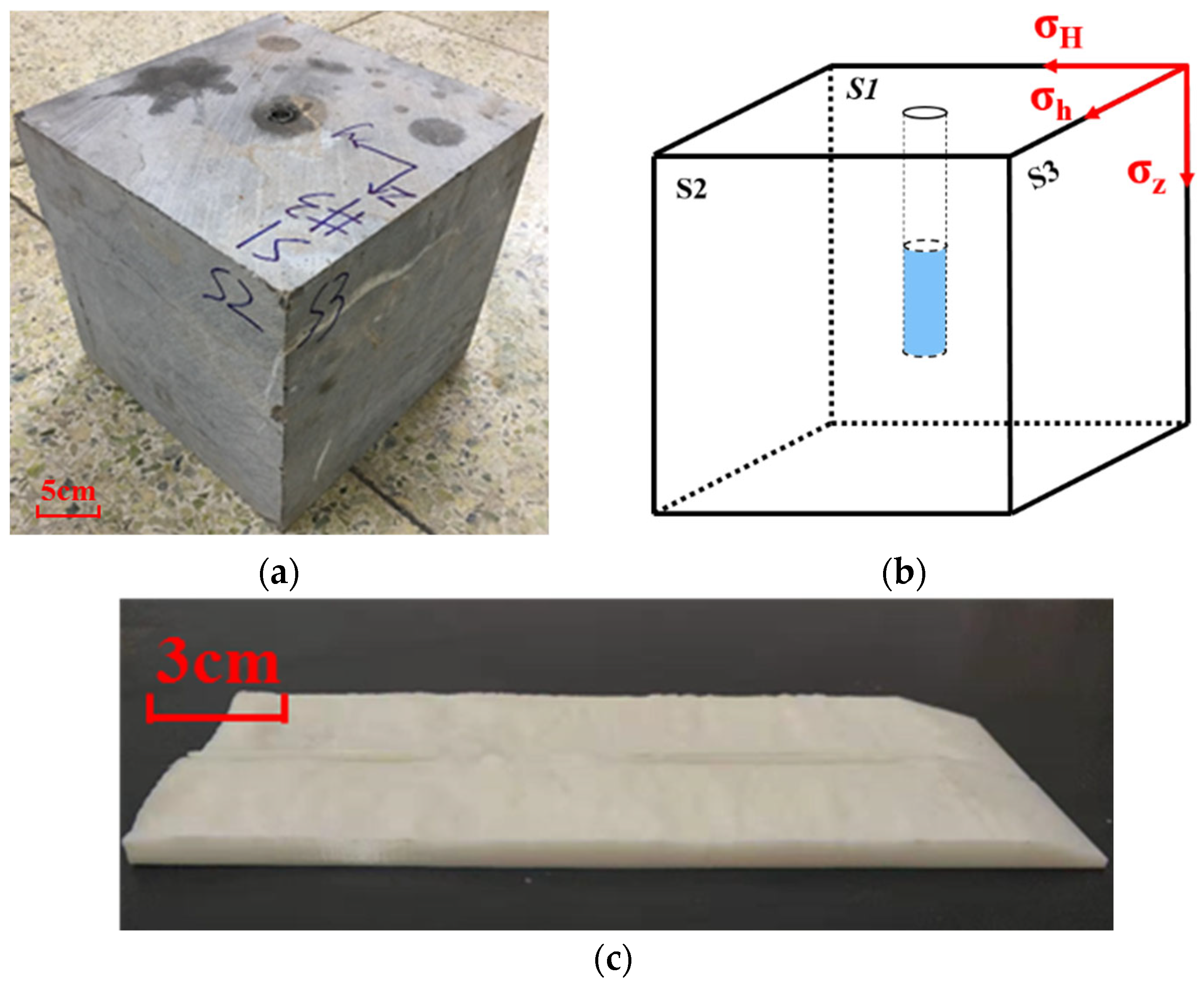
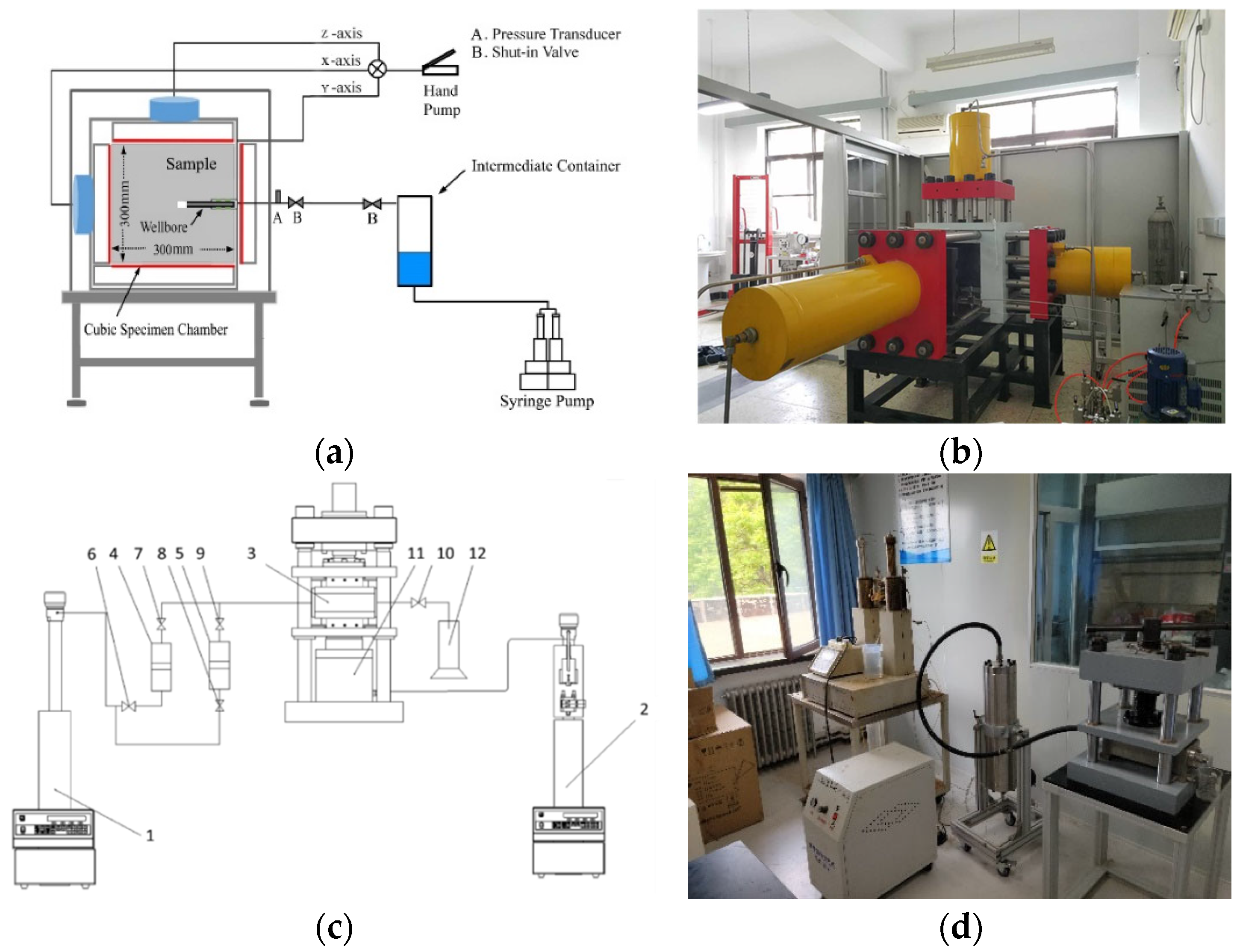
2.1. Experimental Setup

Triaxial fracturing equipment was applied for the temporary plugging and for diverting the fracturing experiment, as shown in Figure 1a,b. The equipment consisted of a hydraulic stress loading system, a cubic specimen chamber, a syringe pump, an intermediate container, and a data acquisition device. The hydraulic stress loading system was used for loading principal stress in three independent directions. According to the applied stress, the fracturing of the horizontal well and the vertical well can be simulated, respectively. According to the installation requirements, the wellbore direction of the sample was always along the x-axis direction. Therefore, when the vertical stress was applied in the x-axis direction, it was vertical well fracturing, and when the vertical stress was applied in the z-axis direction, it was horizontal well fracturing. For experiments in this study, in order to simulate the temporary plugging and diverting in vertical well fracturing, vertical stress was applied on the x-axis, while the minimum horizontal principal stress and the maximum horizontal principal stress were applied on the y-axis and the z-axis, respectively. The syringe pump with two independent liquid cylinders had a maximum injection rate of 300 mL/min, which was enough to pump the fracturing fluid with the diversion agent into the sample. The fracturing fluid is stored in an intermediate container made of Hastelloy. Although the diversion agent and the fracturing fluid used in this study were not corrosive, Hastelloy itself is more stable and can be competent for storage in other studies, such as acid fracturing. The data acquisition device included a pressure sensor with a measurement range of 0–60 MPa, which was used to monitor the bottom hole pressure. Then, the pressure data will be synchronized to the software in real-time for recording and monitoring. A safe pressure (e.g., 50 MPa) will be set before the experiment. If the pressure continues to rise after reaching the upper limit, the experiment will be stopped until there is no abnormality in the connection between equipment and pipeline, and then the sample will be replaced to repeat the experiment.
The experimental equipment used to evaluate the temporary plugging ability of the diversion agent is shown in Figure 1c,d. In addition to the injection pump, intermediate container, and data acquisition equipment, the equipment also had a rock plate holder and diversion chamber. The holder was used to install the rock plate used in the experiment and then placed in the diversion chamber. The diversion chamber was placed in the working space of the test bench. The size of the working space was adjusted by rotating the handle so as to pressurize and to stabilize the diversion chamber.

2.2. Specimen Preparation

The outcrops gathered from Baikouquan formation in Junggar Basin, China were cut into 300 × 300 × 300 mm3 cubes to study temporary plugging and diverting fracturing. A blind hole with a length of 200 mm and a diameter of 20 mm was drilled at the center of one of the planes to simulate the well. Then, a steel cylinder with a length of 100 mm and a diameter of 15 mm was fixed in the blind hole with glue and PTFE, which left a 100 mm openhole section at the bottom of the well, as shown in Figure 2a. For the convenience of description and analysis, the plane where the wellbore is located is marked as S1 and its opposite side is marked as S6. The vertical stress is to be applied on these two faces. The other four surfaces are marked as S2, S3, S4, and S5, respectively, where S2 and S5 are opposite and S3 and S4 are opposite. The minimum horizontal principal stress was applied on the S2 and S5 plane and the maximum horizontal principal stress was applied on the S3 and S4 plane. The final processed schematic specimen is shown in Figure 2b.
The above rock blocks can also be reused after fracturing. Select appropriate positions on both sides of the split fracture surface for cutting and processing into rock plates for temporary plugging performance evaluation experiment so as to realize the temporary plugging of the diversion agent in the actual rough fracture surface. However, it was difficult to avoid the wear of the fracture surface in each temporary plugging experiment. Therefore, in order to ensure the same experimental environment for each group, the surface of the real split rock plate was optically scanned, and then the scanning results were restored to the real object by 3D printing, and a rock plate with the size of 21 mm × 3.8 mm × 15 mm was made, as shown in Figure 2c. 15 mm refers to the total thickness of the two rock plates together. Since the surface of the rock plate was restored from the real fracture surface, the two rock plates can fit together perfectly. At the same time, in order to play the role of drainage, so that the diversion agent can smoothly enter the fracture without being stuck at the entrance, two wedge-shaped surfaces are cut out at the entrance section of the rock plate. The material used for 3D printing of the rock plate was abs-m30 plastic, with Young’s modulus of 27.7 GPa, a tensile strength of 33 MPa, and a bending strength of 64 MPa. The rock plate printed with this material can meet the experimental requirements and can be reused, while ensuring the restoration of the rough surface of the real split rock plate and making the results more comparable.
The two rock plates are, respectively, fixed in the two grooves of the holder. When they are spliced together, the rock plate can fully fit. At this time, the fracture width is 0. The width can be adjusted by placing shims with different thicknesses in the middle of the holder to meet the needs of different experiments. After the holder was spliced and fixed in the diversion chamber, the diversion chamber was put into the working space of the experimental desk, and the size of the working space was adjusted by rotating the handle to realize the pressurization and the stability of the diversion chamber.

2.3. Specimen Preparation

In the temporary plugging and diverting fracturing experiment, the displacement was set to 60 mL/min, and regarding the typical value on-site the horizontal stress difference was adopted as 15 MPa. According to the loading capacity of the equipment, the minimum horizontal principal stress was set to 10 MPa, the maximum horizontal principal stress was set to 25 MPa, and the vertical stress was set to 20 MPa. Considering that the width of the fracture caused in the experiment was generally less than 1 mm, the diversion agents used in the experiment were 20/60 mesh powder and 1 mm granules, respectively.
In the plugging performance evaluation experiment of the diversion agent, the interval (i.e., fracture width) between two rock plates was set as 6 mm, which is a typical width in the field, and the displacement was set as 60 mL/min. The size of the diversion agent is different according to different experimental purposes. For diversion inside the fracture, to make it easier for the temporary plugging granules to enter the fracture, the size of granules should be smaller than the fracture width. Therefore, 1–5 mm granules + 20/60 mesh powder were selected as diversion agents for the experiment. The dosage of the diversion agent is shown in the table. For the diversion at the inlet of the fracture, the diversion agent did not need to fill the entire fracture, only to accumulate at the inlet of the fracture and hold up enough pressure. Therefore, the size of granules should be greater than the fracture width, and the amount of the diversion agent is shown in Table 1.

2.4. Experimental Procedure

2.4.1. Triaxial Fracturing Experiment

The injection process of the triaxial fracturing experiment is divided into two stages. In the first stage, ordinary high viscosity fracturing fluid is injected to open the first fracture. In the second stage, fracturing fluid mixed with a diversion agent is injected to form a plugging at the inlet of the fracture or inside the fracture, and new fractures are opened in other places. The diverting effect is analyzed by anatomizing rocks along with fractures after the experiment. The experimental procedures are as follows:
  • Preparation of fracturing fluid.
Before the formal fracturing experiment, the fracturing fluid needs to be pre-configured and poured into the intermediate container. In the simulation experiment of temporary plugging and diverting fracturing, two kinds of fracturing fluids are used in total. The first is ordinary high viscosity fracturing fluid. On this basis, the second fracturing fluid is prepared by adding temporary plugging granules, while stirring the high viscosity fracturing fluid.
2.
Specimen fixing.
Place the sample in the cube sample chamber, with the S1 plane perpendicular to the X-direction, S2 plane perpendicular to the Y-direction, and S3 plane perpendicular to the Z-direction.
3.
Stress loading.
To uniformly load the stress in three directions, all stresses need to be loaded to 5 MPa in advance. Then, the triaxial stress is loaded to the target stress according to the experimental scheme.
4.
Fracturing.
Firstly, ordinary high viscosity fracturing fluid is injected into the well at the target injection rate through the syringe pump for initial fracturing. When the fracturing fluid fills the pipeline and wellbore, it will deposit at the bottom of the well, which will cause the bottom hole pressure to rise continuously and rapidly. When the bottom hole pressure drops sharply, it means that the fracture opens. At the laboratory scale, the fracture will expand to the rock surface almost instantaneously, accompanied by a dull fracture sound. After continuous injection for a while, replace the fracturing fluid with that mixed with the diversion agent for repeated fracturing. When the sample is fractured again, stop the injection, and end the experiment.
5.
Anatomizing rocks along with fractures.
Remove the sample after the experiment. The fracture opened by high viscosity fracturing fluid is obvious. The strength is further damaged by knocking along the fracture so that the sample is anatomized. Thus, the distribution of diversion agents in the sample can be seen, and the law of fracture expansion and diverting can be analyzed.

2.4.2. Diversion Pressure Test of Diversion Agents

The performance evaluation experiment of the diversion agent includes two parts. The first part is to optimize the dosage of the diversion agent through a diversion experiment to be competent for temporary plugging inside the fracture and at the inlet of the fracture, respectively. The second part is to verify the degradability of the diversion agent at formation temperature and confirm that it will not cause permanent plugging. The experimental procedures are as follows:
(1)
Prepare the fracturing fluid containing the diversion agent and put it into the intermediate container;
(2)
The 3D printing rock plate is installed in a holder, and the thickness of the shims is adjusted to simulate different slit widths. Then, the holder is spliced together and put into the diversion chamber;
(3)
Fix the diversion chamber on the experimental desk, connect its inlet with the intermediate container through a special pipeline, and the outlet leads to the measuring cylinder;
(4)
Connect the pressure sensor and open the pressure acquisition software. At the same time, start the syringe pump to inject liquid at a certain displacement. Stop the pump after all the fracturing fluid in the intermediate container flows out or the pump pressure is held up to 20 MPa;
(5)
Stop data collection. Take out the 3D printed rock plate and observe the distribution of the diversion agent in the rock plate;
(6)
Clean the experimental instruments;
(7)
Draw the curve of pressure changing with time, and analyze the experimental data.

2.4.3. Stability and Degradability Evaluation of Diversion Agents

A qualified diversion agent not only needs to have sufficient plugging capacity but also good stability at high temperatures to effectively plug fractures during construction. In addition, it should meet the requirements that the diversion agent can be completely degraded after the work is completed and finally discharged back to the formation with the fracturing fluid, that is, the diversion agent has good degradation performance.
To verify the stability and degradability of temporary plugging granules, take an appropriate number of samples, put them into the high-temperature reactor, and add enough formation water. Put the reactor into the incubator, keep it at 60 °C, take it out every hour, observe its state, and judge whether it is degraded.

3. Result and Discussion

3.1. Diverted Fracturing Experiment

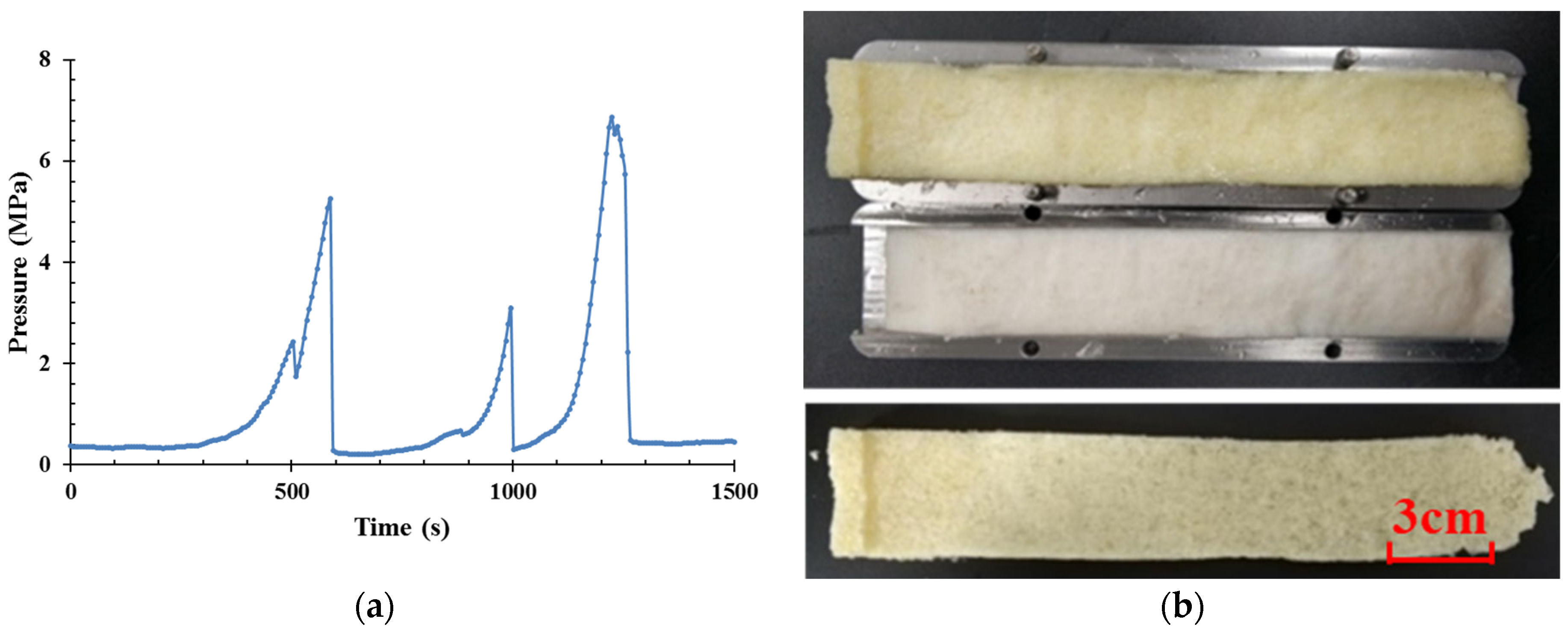
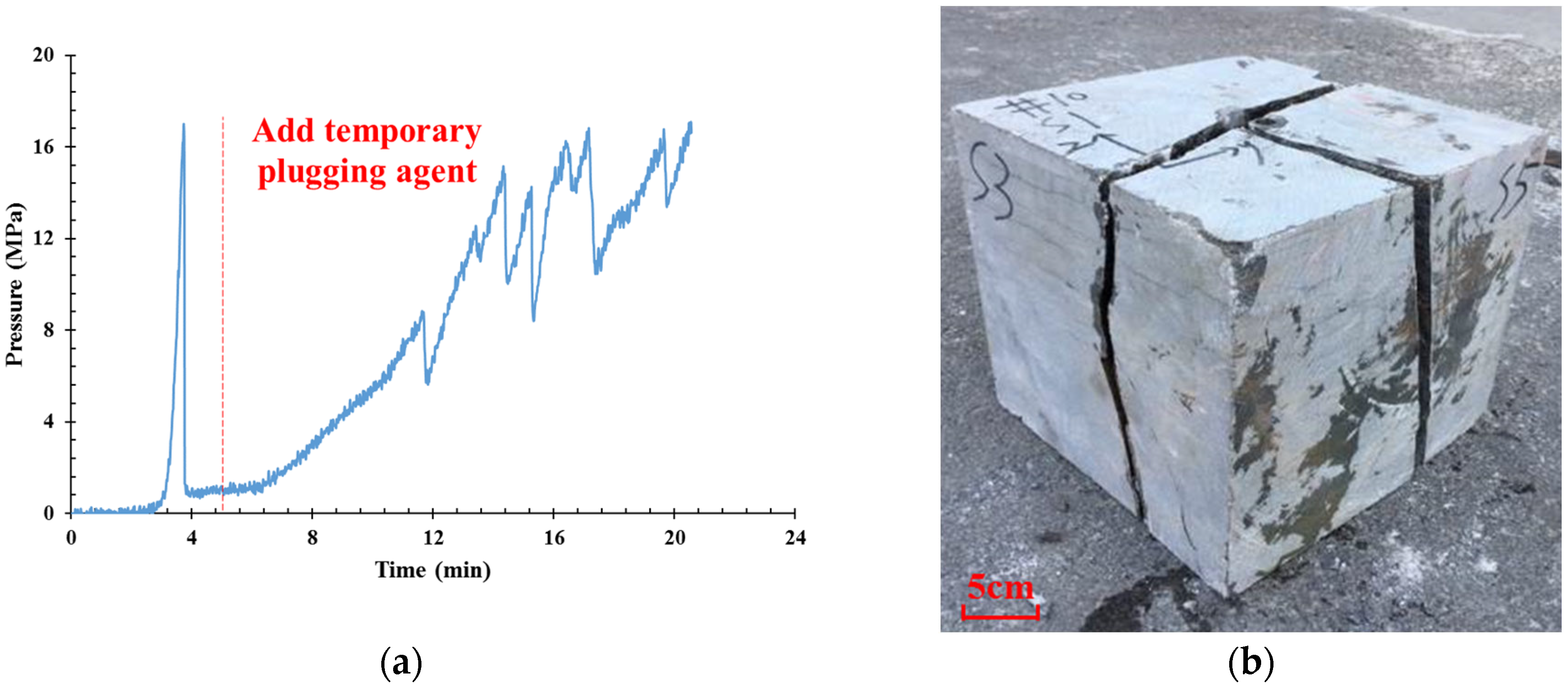
3.1.1. Diversion Inside the Fracture

The curve reflecting the change of pressure with time during fracturing is shown in Figure 3a. By analyzing the change of pressure, it can be found that it is divided into two stages, which exactly correspond to the two pumping processes. And the red dotted line is the dividing line between the two stages. In the first stage, the fracturing fluid is deposited at the bottom of the well, resulting in the rapid rise of the bottom hole pressure. When the pressure reaches 12 MPa, it suddenly drops, forming an obvious fracture display, accompanied by the dull fracturing sound of the rock sample. As the fracture extends to the surface of the rock sample in a short time, the fracturing fluid flows to the outside along the fracture, and the subsequent pressure will not rise. After the above analysis, it can be judged that only one fracture was opened at this stage. In the second stage, fracturing fluid mixed with a diversion agent is injected. Initially, the pressure is low and starts to rise slowly after a few minutes. This is because the diversion agent enters the fracture to form a high resistance zone, which prevents the extension of the fracture and increases the net pressure in the fracture. After that, the pressure rises higher and wildly fluctuates. The pressure has been cyclically rising and falling, and finally reaches 20 MPa, indicating that new fractures are opening in this state.
The fracture geometry after the experiment is shown in Figure 3b. The first fracture is approximately perpendicular to the minimum principal stress, the second fracture starts near the wellbore, and it is approximately perpendicular to the direction of the maximum horizontal principal stress. At the same time, it can be observed that the diversion agent is dispersed and laid in the fracture. Due to the narrow fracture, even loosely distributed temporary plugging also plays a good role in blocking, and it can hold up a high enough pressure. The test results show that after the fracture is opened, injecting a diversion agent can form a high-resistance temporary plugging zone in the fracture, thereby increasing the net pressure in the fracture and opening new fractures at the weak position. In this process, if a bedding plane or natural fracture with poor bonding strength is encountered, it can also be opened, which will increase the complexity of the fracture.

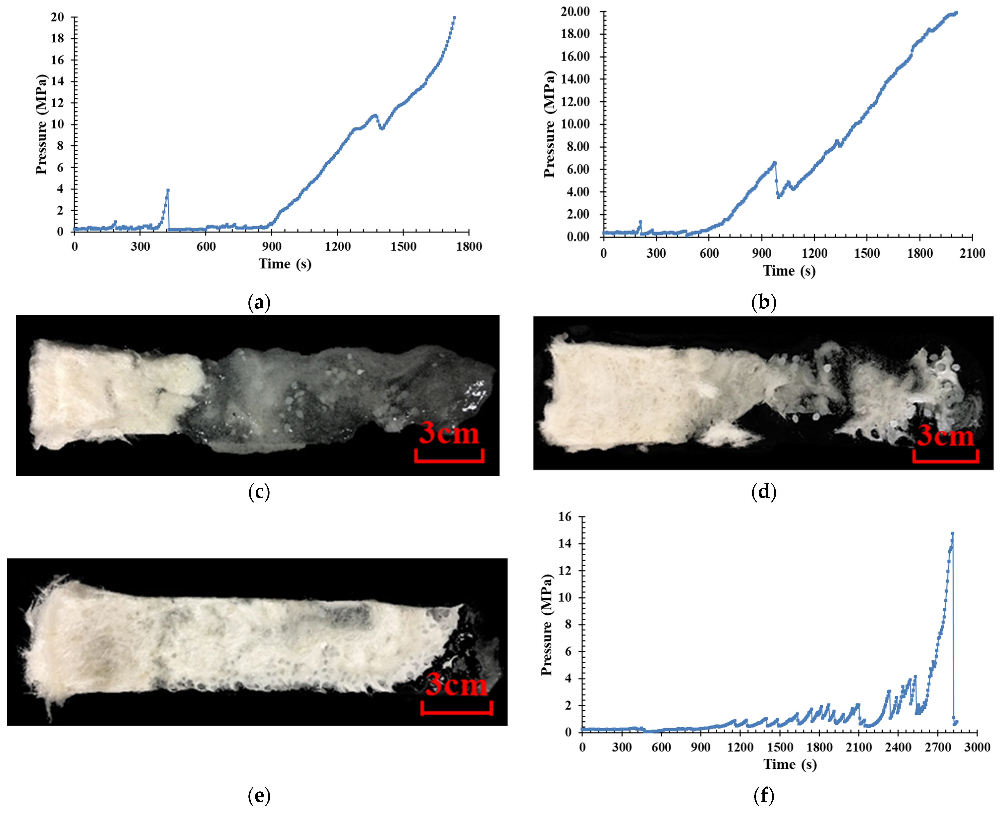
3.1.2. Diversion at the Inlet of the Fracture

The change in bottom hole pressure is shown in Figure 4a. Like the experiment of temporary plugging inside the fracture, the curve can be divided into two parts, corresponding to the two pumping stages. The red dotted line is the dividing line between the two stages. According to the curve, the fracture point of the first fracture is obvious. At this time, the first fracture is opened. Similarly, the fracture instantly extends to the rock surface and the fracturing fluid flows out directly along the fracture, so the pressure is directly reduced to a low value. After that, the diversion agent is injected. After the initial filling pipeline and wellbore stage, the diversion agent enters the first fracture opening and forms temporary plugging at the inlet of the fracture. At this time, the pressure begins to rise and violently fluctuates, indicating that new fractures are being opened inside the rock.
The fracture geometry after the experiment is shown in Figure 4b. The diversion agent did not enter the fracture but accumulated at the opening, which formed a good plugging effect and caused high pressure. Two fractures were opened on the rock sample. The first fracture was perpendicular to the direction of the minimum horizontal principal stress, and the second fracture whose initiation position was on the wellbore was perpendicular to the direction of the maximum horizontal principal stress.

3.2. Performance Evaluation of Diversion Agent

The results of the plugging evaluation experiment of the diversion agent are shown in Table 2.

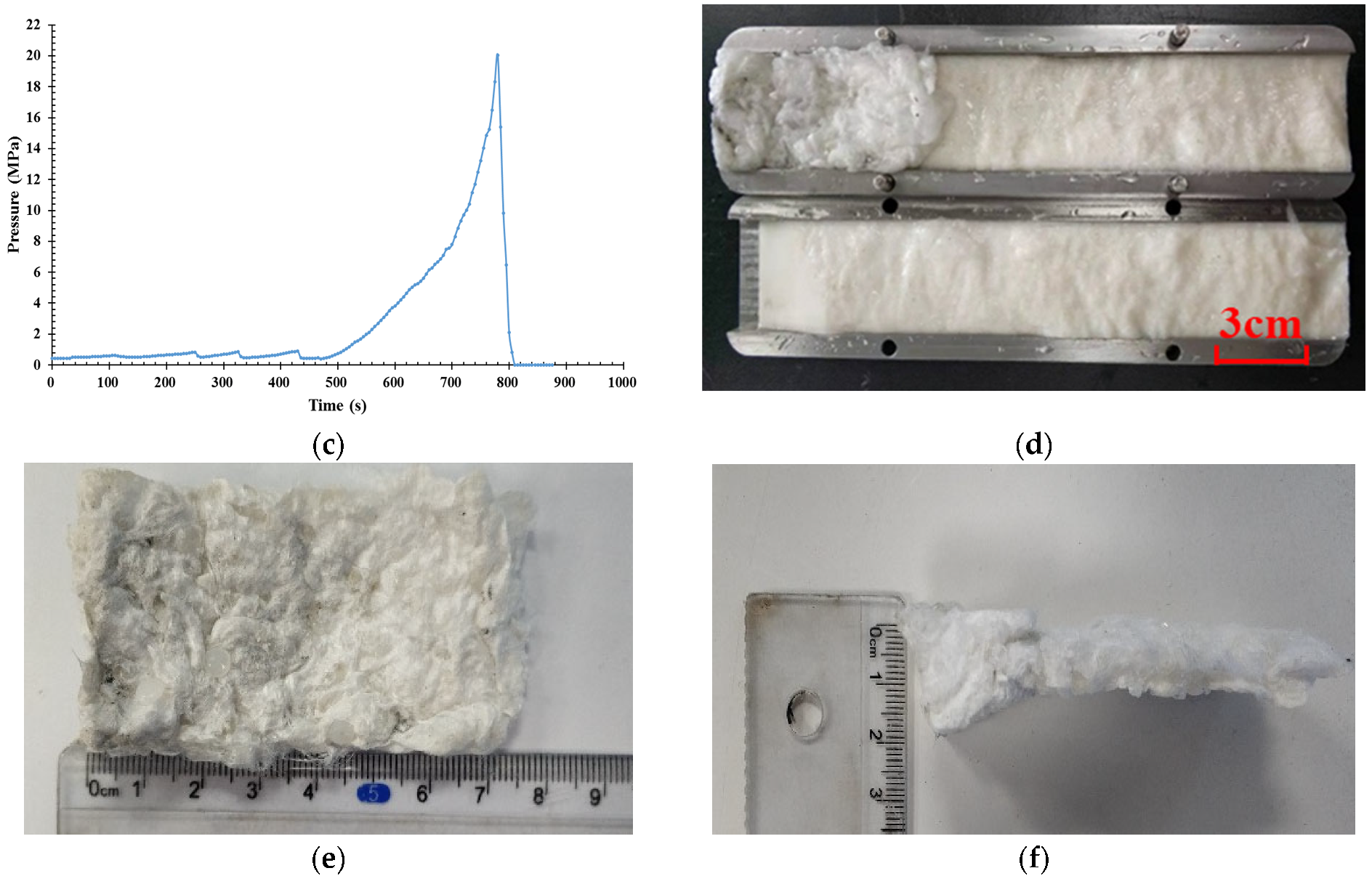
3.2.1. Diversion Inside the Fracture

The increase in net pressure does not need to be very high during the temporary plugging inside the fracture. However, in experiment 1, when the diversion agent with a concentration of 2 wt% was used, the displacement pressure was not increased in the whole process. So, it cannot meet the needs of temporary plugging. In experiment 3, after the concentration of the diversion agent was increased to 4 wt%, the displacement pressure increased to 6.9 MPa, which indicates that with the increase of the diversion agent concentration, the temporary plugging inside the fracture can be realized and the effect is good. In experiment 2, the temporary plugging granules with the specification of 1–4 mm can still increase the net pressure in the fracture by 4.5 MPa, which means that for temporary plugging inside the fracture, even if the size of the diversion agent is small, a temporary plugging zone of particle bridging and powder filling can be established in the fracture at a relatively high dosage.
The pressure curve of experiment 3 is shown in Figure 5a. The pressure has been maintained at a low level since the beginning of the experiment, and no effective plug was formed. After a period of displacement, the clear liquid and the fracturing fluid carrying the diversion agent flow out alternately at the outlet, and an obvious pressure increase begins to appear in approximately 10 min. After s multiple pressure relief, the pressure reaches a maximum of 6.9 MPa, which meets the requirements of temporary plugging inside the fracture. The pressure change throughout the whole process indicates that the plugging is an iterative process, which leads to the final formation of a dense plugging zone, as shown in Figure 5b. And by weighing, the weight of the temporary plugging belt after drying is 10.64 g.

3.2.2. Diversion at the Inlet of the Fracture

The pressure curve of experiment 4 (1–7 mm granules + 20/60 mesh powder) is shown in Figure 6a. The first pressure increase began at approximately 3 min after the displacement, but the pressure dropped after only 4.33 Mpa, indicating that the formed plugging zone was washed away. As the displacement progressed, the pressure rose for the second time and reached 11.8 Mpa until approximately 15 min. After that, the high pressure was not held up until the end of the experiment. After opening the rock plate, the shape of the temporary plugging zone can be observed, as shown in Figure 6b. It can be seen that the granules aggregated at the inlet end to form a temporary plugging layer, and at the same time, a large number of temporarily plugging granules were carried by the fracturing fluid into the depths of the rock plate, and the formed temporary plugging zone spread over the entire surface. Although the pressure of 11.8 Mpa was successfully held up by using the diversion agent scheme of granules and powders in this experiment, the formation of the temporary plugging zone took a long time, and the consumption of the diversion agent was large. Therefore, it can only be said that the goal of temporary plugging has been partially achieved.
The pressure curve of experiment 5 (1–7 mm granules + 20/60 mesh powder + fiber) is shown in Figure 6c. The pressure in the early stage of the experiment has been maintained at a low value. At this time, the fracturing fluid passes through the simulated fracture very smoothly. Then, flows out from the outlet end of the diversion chamber. Starting from approximately 8 min, the temporary plugging zone gradually formed and stabilized. At this time, the pressure began to rise continuously, and the rising rate gradually increased. Finally, the pressure reached 20 Mpa, which is also the safe pressure set in the experiment. Then, the pump was stopped and the pressure dropped sharply. Open the rock plate to observe the shape of the temporary plugging zone, as shown in Figure 6d–f. At the inlet end of the rock plate, an obvious temporary plugging zone is formed. The main body of the temporary plugging zone is fibers, and the particle balls are wrapped and covered inside the fibers. It can be seen from the figure that the temporary plugging zone is relatively thick and dense. After the temporary blocking agent was taken out to dry, its length was measured to be approximately 7.5 cm. This size and density can ensure an excellent plugging. The results show that the addition of fibers can effectively improve the success rate of temporary plugging and reduce the consumption of the diversion agent. Additionally, by weighing, the weight of the temporary plugging belt after drying is 9.33 g.
The results of experiment 6 (1–6 mm granules + 20/60 mesh powder + fiber) and 7 (1–5 mm granules + 20/60 mesh powder + fiber) are similar and the pressure curves are shown in Figure 7a,b, respectively. After a longer period of construction, a stable temporary plugging zone was finally formed, and its pressure bearing capacity reached 20 MPa. Compared with experiment 5, the largest granule diameter in the diversion agent used in experiments 6 and 7 is smaller, and their diameter are equal to and less than the fracture width, respectively. The result of the change in granule size is a slower build-up of the temporary plugging zone at the inlet of the fracture. When the maximum granule diameter is 7 mm, the pressure increases to 20 MPa in approximately 300 s, while when the maximum granules diameter is reduced to 6 mm and 5 mm, this time is extended to 900 s and 1500 s, respectively. After the experiment, open the holder and carefully remove the temporary blocking zone, as shown in the Figure 7c,d. It is obvious that in both schemes a dense and stable temporary plugging zone is formed at the inlet of the fracture, the main body of which is large granules, and the antiparticles are filled by small sized granules and fibers.
The diameter of maximum granules used in experiment 8 is only 4 mm, and its results are completely different from the previous experiments. Experiment 8 did not eventually form an effective plugging at the inlet of the fracture due to its difficulty in forming a buildup at the fracture opening. The grain size of 4 mm was so small that it could easily enter the fracture, so it finally formed an effect similar to temporary plugging inside the fracture, as shown in the Figure 7e. The pressure curves of experiment 8 are shown in Figure 7f. From the pressure change, it can be inferred that during displacement, granules and fibers try to form temporary plugging zones many times, corresponding to each pressure fluctuation. However, the pressure of each time is between 2–4 MPa, indicating that the plugging strength is limited. After many cycles of aggregation and dispersion of the diversion agent, a temporary plugging zone with high strength is finally formed. At the same time and compared with experiment 2, although the whole plugging time becomes longer after reducing the dosage of the diversion agent, the compactness of the temporary plugging zone has been significantly improved due to the addition of fiber, and the maximum pressure has reached 14.7 MPa. It is proved again that the addition of fiber is helpful to improving the strength of a temporary plugging zone.

3.2.3. Evaluation of Stability and Degradability of Diversion Agent

Figure 8 shows the state of the diversion agent at different times. The diversion agent begins to dissolve at 2 h and completely dissolves at 6 h. The experimental results show that the diversion agent has good stability at high temperatures and can effectively plug the fractures during the construction period. At the same time, the diversion agent also has a good degradation performance so as to ensure that it can be completely degraded, flowed back after the construction is completed, avoiding negative effects on the plugged fractures.

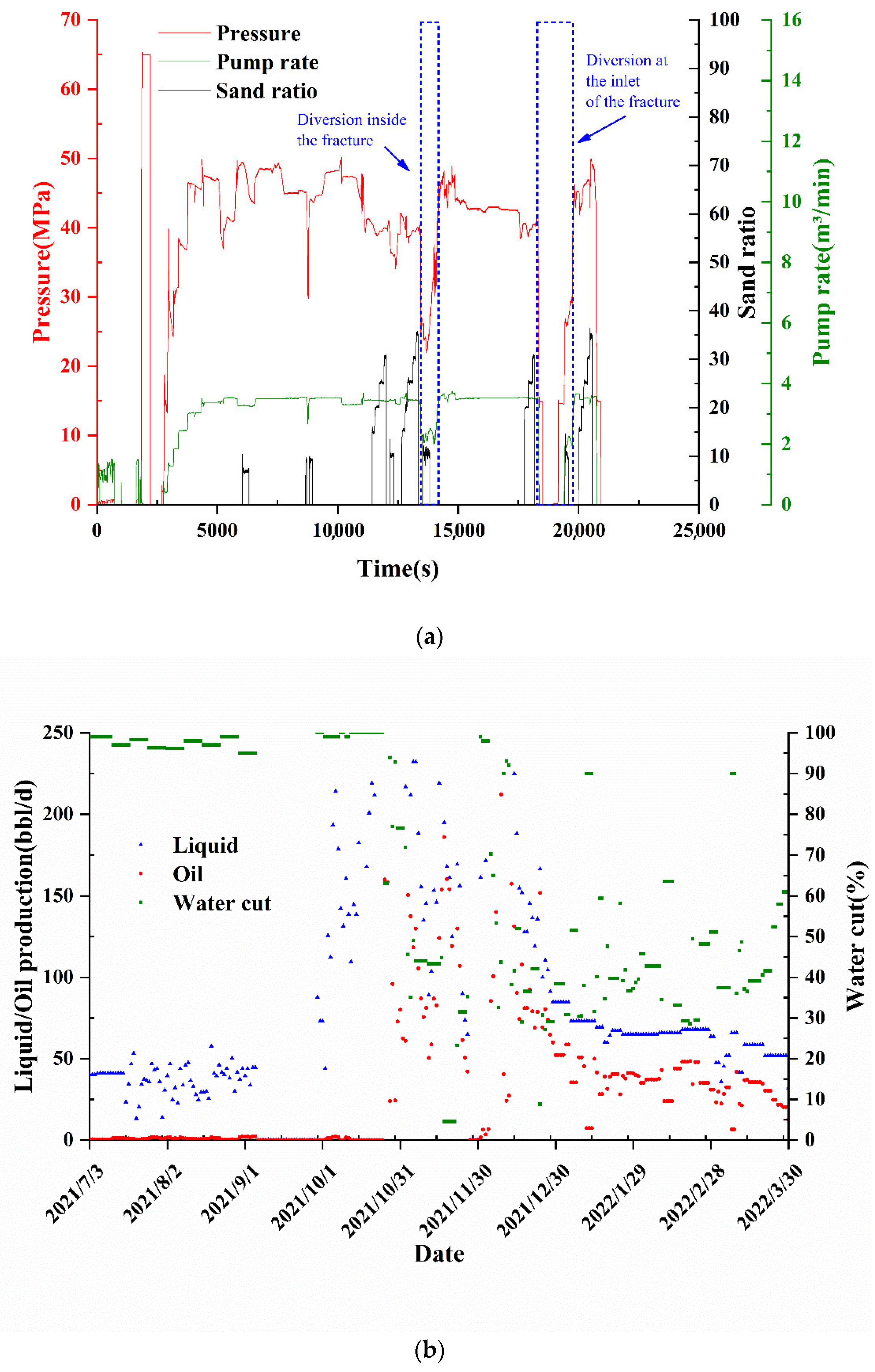
4. Field Application of Diverted Fracturing

4.1. Design Idea of Diverted Fracturing

The target layer to be reconstructed for well b20104 in bai21 district is divided into upper and lower layers of which the lower layer has a thickness of 5.5 m and a span of 34 m, while the upper layer has a thickness of 20 m and a span of 52 m. Since the well has a wide span, a large number of longitudinal small layers, and strong heterogeneity, according to the requirements of fracturing stimulation, the well decided to adopt the split-layer fracturing operation named 2-seals and 2-pressures. At the same time, the process of pre-slippery water + small-diameter quartz sand slug + multiple temporary plugging inside the fracture + temporary plugging at the inlet of the fracture were adopted to create multiple fractures. This results in intensive longitudinal deformation of the reservoir, increasing fracture complexity, and increasing the seepage volume of crude oil from this well.
There is no corresponding injection well around well b20104, and it is 1490 m away from the adjacent well connected to this well in layer T2k1, so the possibility of pressure channeling is very small. Therefore, this fracturing reconstruction can appropriately increase the fracturing scale, and the designed support fracture length is 130 m.

4.2. Design of Dosage of Diversion Agent

According to the perforation information, there are 2–4 perforations in each section. In order to increase the complexity of the fractures and increase the contact volume of the reservoir, the temporary plugging operation is performed in each fracture. Moreover, in order to open each perforation, the temporary plugging operation is performed in each opening. The calculation method of the amount of the diversion agent is shown in Formula (1):
M = m × H × L h × l × S F ,
where M is the actual amount of the diversion agent, kg. m is the amount of the diversion agent in the experiment, kg. H is the actual fracture height, m. h is the fracture height in the experiment, m. L is the length of the actual temporary plugging zone, m. l is the length of the temporary plugging zone in the experiment, m. SF is the redundancy coefficient, and generally the value is 0.1–0.2.
For the experiment of temporary plugging inside the fracture, the fracture height is 3.8 cm, the length of the temporary plugging zone is 10 cm, and the mass of the temporary plugging belt is 10.64 g. Assuming that the fracture height is 25 m in actual operation, a temporary plugging zone that is 2 m long needs to be established in it and to provide a pressure increment of 8 MPa. Through the above formula, the amount of the diversion agent in the single-sided fracture is calculated to be approximately 140 kg.
For the temporary plugging at the inlet of the fracture, the fracture height is also 3.8 cm in the experiment, the length of the temporary plugging zone is 7.5 cm, and the weight of the temporary plugging zone is 9.33 g. Assuming that the fracture height is 30 m, in order to increase the construction effect as much as possible, a higher temporary plugging standard needs to be adopted, so the length of the temporary plugging zone is designed to be 60 cm. According to the above formula, the amount of the diversion agent in the single-sided fracture is calculated to be approximately 65 kg.
In summary, considering the redundancy, the diversion agent used in the fracture is 1–5 mm granules + 20/60 mesh powder, and the dosage of each section is 280 kg. The diversion agent used at the inlet of the fracture is a temporary plugging ball + 1–7 mm granules + 20/60 mesh powder + fiber. The number of temporary plugging balls should be roughly equal to the number of perforation holes, and the amount of the diversion agent is approximately 160 kg.

4.3. Design of Pump Schedule

FracproPT software was used to optimize the hydraulic fracturing operation parameters with the optimized result in 4.1 as the target. Based on the geological situation of the well area, construction data and the simulation results of the fracturing software, the ratio of the designed pre-fluid is approximately 42–49%, which can create a good fracture geometry for the subsequent sand addition stage. According to the construction data of the neighboring wells in this block and the simulation results of the fracturing software, the average sand ratio of this operation is approximately 23%, and a sand ratio of 40% can be adopted at the end of the operation to improve the conductivity of fractures around the wellbore. The well adopts tubing fracturing, and based on the construction data and the calculation of the wellhead pressure at different displacements, the maximum displacement of this operation was 3.5 m3/min. In order to completely transform the target formation, the fractures established in this operation need to communicate with the more distant reservoir as far as possible, and be able to ripple through a larger seepage area. Therefore, the sand addition strength was chosen to be approximately 4.8 m3/m, with a total sand volume of approximately 140 m3 into the well. The construction parameters are shown in Table 3, and the designed pumping procedure is shown in Table 4.

4.4. Design of Pump Schedule

Figure 9a shows the multiple treating curves during the fracturing operation of well b20104, including injection rate, sand ratio, and bottomhole pressure. After the initial pressure test, fracturing fluid was pumped into the formation to open the fractures and fracture points were evident during this process. Subsequent injections of fracturing fluid and proppant carrying fluid continue to extend the fracture, with extension pressure and displacement simultaneously changing. Overall, the pressure is relatively stable in this process. The diversion inside the fracture started at approximately 3 h and 44 min. The specific construction process was to first reduce the displacement to add the diversion agent from the sand mixer, and then the displacement returns to the original value. After the diversion agent entered the fracture, the pressure rose by approximately 3.8 MPa and fluctuated, and the rupture behavior was obvious, indicating that the temporary plugging experiment had worked and achieved a good effect. After that, the pressure started to fall again, indicating that the newly opened fracture was extending further. The diversion at the inlet of the fracture starts at approximately 5 h and 6 min. Before construction, the pump needs to be stopped first, then the temporary plugging ball and the diversion agent was added from the high-pressure pipeline and the sand mixer. When the diversion agent reaches the fracture, the pressure increases obviously. After increasing the displacement, the maximum pressure increases by 5.5 MPa under continuous proppant addition, and then suddenly falls back, indicating that new fractures have spontaneously opened at other positions.
According to the production data of well b20104 (Figure 9b), it can be seen that the daily oil production before fracturing was below 3.65 bbl/d and almost in a state of non-production. The initial production after temporary plugging and diverting fracturing was more than 146 bbl/d, and after two months the production was stabilized at approximately 36.5 bbl/d, indicating a significant increase in production. The results of field application show that the temporary plugging and diverting fracturing operation has a good transformation effect on well b20104 in the Baikouquan reservoir.

5. Conclusions

The purpose of this study is to explore the feasibility of layered fracturing in the Baikouquan reservoir by using temporary plugging diverting fracturing technology, and to optimize the reliable amount of the diversion agent for operation.
(1)
The triaxial fracturing experiment shows that diverted fracturing can be achieved by temporarily plugging inside the fracture or at the inlet of the fracture, which can lead to secondary opening of new fractures and complex fracture geometry;
(2)
With reference to the actual fracture width of 6 mm, based on experiments of plugging evaluation of temporary plugging agent, a 4 wt% concentration of 1–5 mm granules + 20/60 mesh powder was selected for temporary plugging in the fracture, and by using this scheme, the displacement pressure can reach 6.9 MPa, which can meet the requirement of diversion inside the fracture;
(3)
It is appropriate to use 3 wt% concentration of 1–7 mm granules + 20/60 mesh powder + fiber for diversion at the inlet of the fracture. This temporary plugging agent scheme with the granules sized larger than the fracture width can not only hold up a sufficiently high pressure (20 MPa) but also build a temporary plugging zone at a fast speed. At the same time, other experiments show that when the largest granule size is equal to or slightly smaller than the fracture width, a dense temporary plugging zone is formed after multiple attempts of plugging and unsealing. However, when the largest granule size is much smaller than the fracture width, due to the ease of entering the fracture, an effective plugging cannot be formed at the inlet of the fracture, but an effect similar to the diversion inside the fracture can be achieved;
(4)
Using the overall fracturing optimization design method, the construction parameters of well b20104 in the Baikouquan reservoir were optimized. Based on the temporary plugging and diverting fracturing technique, a fracturing technology by spontaneously selecting geologic sweet spots was developed for this well. According to the analysis of the operation data, there is a 3–10 MPa pressure increase when there are pump diversion agents, which is a clear sign of fracture diversion. Plugging the fracture mouth gives a faster and a higher pressure incremental. These changes indicate the good adaptability of the fracturing technology of spontaneously selecting geologic sweet spots based on diversion for multiple interbedded, thin, low-permeability layers. Additionally, the post-frac production data also prove the effectiveness of this fracturing technology for Baikouquan oil field. Before this fracturing, the well had almost stopped oil production, while after the stimulation, the initial oil production rate has increased to more than 146 bbl/d.

Author Contributions

Conceptualization, C.T. and J.M.; investigation, C.T. and W.X.; data curation, C.T., H.X. and X.Z.; writing—original draft preparation, C.T. and B.L.; writing—review and editing, C.T. and H.T. All authors have read and agreed to the published version of the manuscript.

Funding

This research was support by Investigation on the Fracture-Driven Interactions Mechanism and Preventive Countermeasures of Mahu. (2017ZX05070).

Institutional Review Board Statement

Not applicable.

Informed Consent Statement

Not applicable.

Data Availability Statement

Not applicable.

Conflicts of Interest

The authors declare no conflict of interest.

References

  1. Tong, S.K.; Gao, D.L. Basic research progress and development suggestions on hydraulic fracturing. Oil Drill. Prod. Technol. 2019, 41, 15. [Google Scholar] [CrossRef]
  2. Warpinski, N.R.; Teufel, L.W. Influence of geologic discontinuities on hydraulic fracture propagation. J. Pet. Technol. 1987, 39, 209–220. [Google Scholar] [CrossRef]
  3. Yang, J.S.; Wang, Y.B.; Li, A.Q.; Chen, Z.H.; Chen, Y.P.; Zou, Y.S. Experimental study on propagation mechanism of complex hydraulic fracture in coal-bed. J. China Coal Soc. 2012, 37, 73–77. [Google Scholar]
  4. Tan, P.; Jin, Y.; Hou, B.; Han, K.; Zhou, Y.C.; Meng, S.Z. Experimental investigation on fracture initiation and non-planar propagation of hydraulic fractures in coal seams. Pet. Explor. Dev. 2017, 44, 439–445. [Google Scholar] [CrossRef]
  5. Li, N.; Zhang, S.C.; Ma, X.F.; Zou, Y.S.; Chen, M.; Li, S.H. Experimental study on the propagation mechanism of hydraulic fracture in glutenite formations. Chin. J. Rock Mech. Eng. 2017, 36, 2383–2392. [Google Scholar] [CrossRef]
  6. Du, Z.H.; Li, J.Q.; Nie, H.L. A Probe of Secondary Deflection Fracturing Treatment in Hydraulic Fractures. Xinjiang Pet. Geol. 2013, 34, 349–353. [Google Scholar]
  7. Rabie, A.I.; Gomaa, A.M.; Nasr-El-Din, H.A. Hcl/formic in-situ-gelled acids as diverting agents for carbonate acidizing. SPE Prod. Oper. 2012, 27, 170–184. [Google Scholar] [CrossRef]
  8. Zhao, M.W.; Gao, Z.B.; Dai, C.L.; Sun, X.; Huang, Y.P. Advancement of Temporary Plugging Agent for Fracturing in Oilfield. Oilfield Chem. 2018, 35, 538–544. [Google Scholar] [CrossRef]
  9. He, C.M.; Chen, H.J.; Wang, W.Y. Diversion Acidizing Used for Carbonate Reservoir: State of The Art and New Development. Pet. Drill. Tech. 2009, 37, 121–126. [Google Scholar] [CrossRef]
  10. Li, B.; Mou, J.; Zhang, S.; Ma, X.; Zou, Y.; Wang, F. Experimental Study on the Interaction Between CO2 and Rock during CO2 Pre-pad Energized Fracturing Operation in Thin Interbedded Shale. Front. Energy Res. 2022, 10, 825464. [Google Scholar] [CrossRef]
  11. Bouazza, A.; Gates, W.P.; Ranjith, P.G. Hydraulic conductivity of biopolymer-treated silty sand. Geotech. 2009, 59, 71–72. [Google Scholar] [CrossRef]
  12. Miller, K.A.; Moore, R.G.; Ursenbach, R.G.; Laureshen, C.J.; Mehta, S.A. Proposed air injection recovery of cold-produced heavy oil reservoirs. J. Can. Pet. Technol. 2002, 41, 3. [Google Scholar] [CrossRef]
  13. Lu, Z.Y. Progress and Prospect Study on Temporary Plugging Agent for Diverting Fracturing. Sci. Technol. Eng. 2020, 20, 12691–12701. [Google Scholar] [CrossRef]
  14. Wang, D.; Zhou, F.; Ge, H.; Yang, S.; Ying, L. An experimental study on the mechanism of degradable fiber-assisted diverting fracturing and its influencing factors. J. Nat. Gas Sci. Eng. 2015, 27, 260–273. [Google Scholar] [CrossRef] [Green Version]
  15. Abdollahi, R.; Esfandyari, H.; Pari, M.N.; Davarpanah, A. Conventional diverting techniques and novel fibr-assisted self-diverting system in carbonate reservoir acidizing with successful case studies. Pet. Res. 2021, 6, 247–256. [Google Scholar] [CrossRef]
  16. Martin, F.; Jimenez-Bueno, O.; Ocampo, A.G.; Ramirez, G.R. Fiber-assisted self-diverting acid brings a new perspective to hot deep carbonate reservoir stimulation in Mexico. In Proceedings of the SPE Latin American & Caribbean Petroleum Engineering Conference, SPE-138910-MS, Lima, Peru, 1–3 December 2010. [Google Scholar] [CrossRef]
  17. Wang, D.; Zhou, F.; Ge, H.; Bo, Y.; Zhang, W. The effect of pore pressure on crack propagation in diverting fracturing. In Proceedings of the 52nd US Rock Mechanics/Geomechanics Symposium, ARMA-2018-327, Seattle, WA, USA, 17–20 June 2018. [Google Scholar]
  18. Liu, H.; Zhao, J.Z.; Hu, Y.Q.; Liu, W.; Hu, G.H.; Li, S.F. Study on mechanism of inducing new fractures for refracturing gas wells. Nat. Gas Ind. 2004, 24, 102–104. [Google Scholar] [CrossRef]
Figure 1. Experimental equipment (a) schematic diagram of triaxial fracturing equipment; (b) physical diagram of triaxial fracturing equipment; (c) schematic diagram of triaxial fracturing equipment (1: Syringe pump; 2: Confining pressure pump; 3: holder; 4&5: Intermediate container; 6–10: valve; 11: engine; 12: Measuring cylinder); (d) physical diagram of triaxial fracturing equipment.
Energies 15 05208 g001
Figure 2. Experimental specimen (a) Physical diagram of specimen for triaxial fracturing test; (b) Schematic diagram of specimen for triaxial fracturing test; (c) 3D printing rock plate.
Energies 15 05208 g002
Figure 3. Pressure curve and fracture geometry of diversion experiment inside the fracture. (a) Pressure curve; (b) Fracture geometry.
Energies 15 05208 g003
Figure 4. Pressure curve and fracture geometry of diversion experiment at the inlet of the fracture. (a) Pressure curve; (b) Fracture geometry.
Energies 15 05208 g004
Figure 5. Pressure curve and temporary plugging zone morphology of experiment 3. (a) Pressure curve; (b) Temporary plugging zone morphology.
Energies 15 05208 g005
Figure 6. Pressure curve and temporary plugging zone morphology of experiments 4 and 5. (a) Pressure curve of experiment 4; (b) Temporary plugging zone morphology of experiment 4; (c) Pressure curve of experiment 5; (df) Temporary plugging zone morphology of experiment 5.
Energies 15 05208 g006aEnergies 15 05208 g006b
Figure 7. Pressure curve and temporary plugging zone morphology of experiment 6–8. (a) Pressure curve of experiment 6; (b) Pressure curve of experiment 7; (c) Temporary plugging zone morphology of experiment 6; (d) Temporary plugging zone morphology of experiment 7; (e) Temporary plugging zone morphology of experiment 8; (f) Pressure curve of experiment 8.
Energies 15 05208 g007
Figure 8. Degradation process of the diversion agent.
Energies 15 05208 g008
Figure 9. The treating curves and production data of well b20104. (a) The treating curves during the fracturing operation; (b) The production data.
Energies 15 05208 g009
Table 1. Experimental scheme for evaluation of the diversion agent.
No.Location of Temporary PluggingSchemeConcentration (wt%)
1Temporary plugging
inside the fracture
1–5 mm granules + 20/60 mesh powder2
21–4 mm granules + 20/60 mesh powder4
31–5 mm granules + 20/60 mesh powder4
4Temporary plugging
at the inlet of the fracture
1–7 mm granules + 20/60 mesh powder3
51–7 mm granules + 20/60 mesh powder + fiber3
61–6 mm granules + 20/60 mesh powder + fiber3
71–5 mm granules + 20/60 mesh powder + fiber3
81–4 mm granules + 20/60 mesh powder + fiber3
Table 2. Experimental results of different temporary plugging schemes.
No.SchemeConcentration (wt%)Plugging Pressure
11–5 mm granules + 20/60 mesh powder20.4
21–4 mm granules + 20/60 mesh powder44.5
31–5 mm granules + 20/60 mesh powder46.9
41–7 mm granules + 20/60 mesh powder311.8
51–7 mm granules + 20/60 mesh powder + fiber320 (max)
61–6 mm granules + 20/60 mesh powder + fiber320 (max)
71–5 mm granules + 20/60 mesh powder + fiber320 (max)
81–4 mm granules + 20/60 mesh powder + fiber314.75
Table 3. Summary of construction parameters.
Fracturing LocationThe First StageThe Second Stage
Pumping rate3.5 m3/min3.5 m3/min
Percentage of pad87.8%73.1%
Total liquid1020.2 m31496.3 m3
Total proppant33 m396 m3
Average sand ratio23.121.9
Table 4. Fracturing pump injection procedure of lower layer of well b20104.
Activities DescriptionLiquidLiquidCumulative LiquidDisplacementSand RatioSandProppantDiversion Agent
(m3)(m3)(m3/min)(%)(m3)(kg)
Pressure testwater77-----
Install protector18-----
Pre-padslickwater20381.5–2.5----
1501882.5–3.5----
14.3202.33.571.040/70 mesh quartz sand-
150352.33.5----
11.1363.43.591.040/70 mesh quartz sand/
150513.43.5----
Padjelly30543.43.5----
Proppantjelly6.7550.13.5151.020/40 mesh quartz sand-
jelly10560.13.5202.020/40 mesh quartz sand-
jelly12572.13.5253.020/40 mesh quartz sand-
jelly4576.13.5301.020/40 mesh quartz sand-
Flushraw liquor7.5583.63.5----
Padraw liquor10593.63.5101.040/70 mesh quartz sand
Padjelly20613.63.5----
Proppantjelly6.7620.33.5151.020/40 mesh quartz sand-
jelly5625.33.5201.020/40 mesh quartz sand-
jelly12637.33.5253.020/40 mesh quartz sand-
jelly6.76443.5302.020/40 mesh quartz sand-
jelly2.9646.93.5351.020/40 mesh quartz sand-
Flushraw liquor7.5654.43.5----
Temporary pluggingslickwater10664.42.0101.040/70 mesh quartz sand280.0
Padslickwater230894.43.5---
Padjelly25919.43.5----
jelly10929.43.5202.020/40 mesh quartz sand-
jelly8937.43.5252.020/40 mesh quartz sand-
jelly4941.43.5301.020/40 mesh quartz sand-
Flushraw liquor7.5948.93.5----
Stop the pump and inject the diversion agent
Temporary pluggingraw liquor10958.93.5101.040/70 mesh quartz sand160.0 + 40 temporary plugging balls
Padjelly20978.93.5----
Proppantjelly6.7985.63.5151.020/40 mesh quartz sand-
jelly5990.63.5201.020/40 mesh quartz sand-
jelly121002.63.5253.020/40 mesh quartz sand-
jelly6.71009.33.5302.020/40 mesh quartz sand-
jelly2.91012.23.5351.020/40 mesh quartz sand-
Flushraw liquor81020.23.5----
Total--1020.2-23.133.0--
Publisher’s Note: MDPI stays neutral with regard to jurisdictional claims in published maps and institutional affiliations.

