
A Review on Industrial Perspectives and Challenges on Material, Manufacturing, Design and Development of Compressed Hydrogen Storage Tanks for the Transportation Sector


Abstract
:1. Introduction
2. Compressed Hydrogen Tank Applications across Transportation
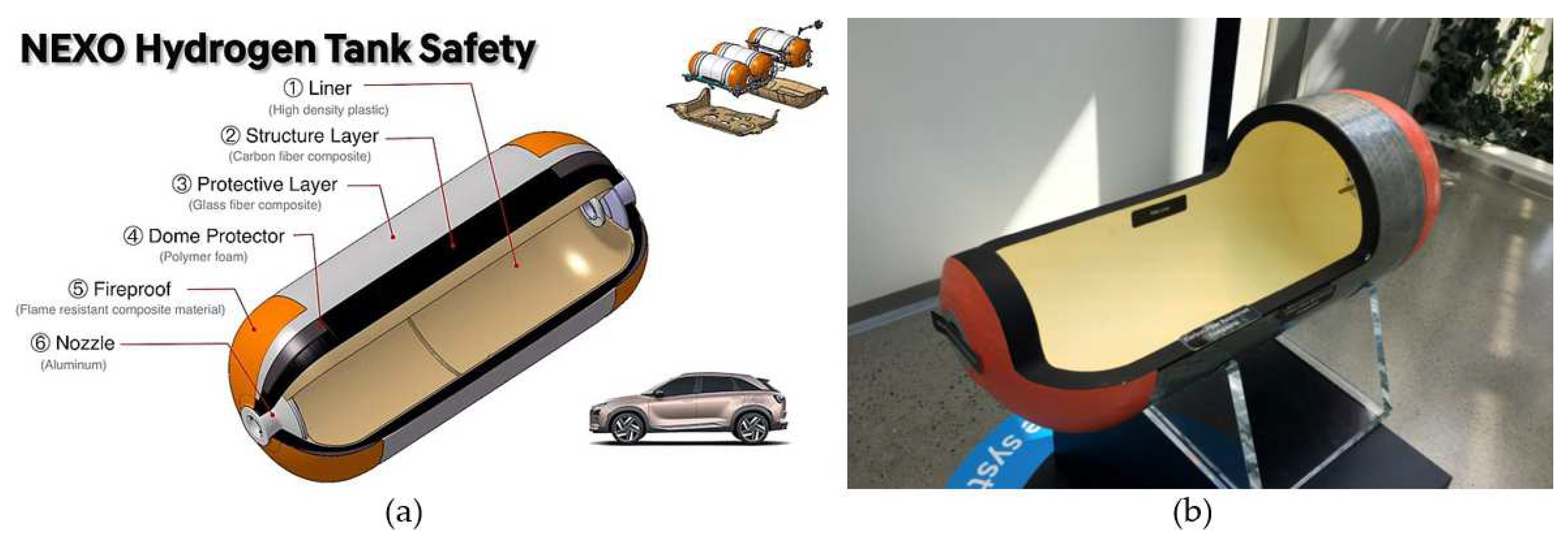
2.1. Light-Duty Vehicles

| Description | Hyundai 2019 Nexo | Toyota 2018 Mirai FCV | Honda 2017 Clarity FCV |
|---|---|---|---|
| Photos |  |  |  |
| Driving distance after one charge (m) | 370 | 312 | 366 |
| Hydrogen tank mass (kg) | 6.33 | 5.00 | 5.46 |
| Motor (kW/lb.ft) | 113 kW/291 lb.ft | 120 kW/247 lb.ft | 100 kW/256 lb.ft |
| Maximum output (hp) | 163 | 154 | 1744 |
| Maximum torque (km·m) | 40.3 | 34.2 | 30.6 |
2.2. Heavy-Duty Vehicles
2.3. Tube Trailers
2.4. Fuel Station
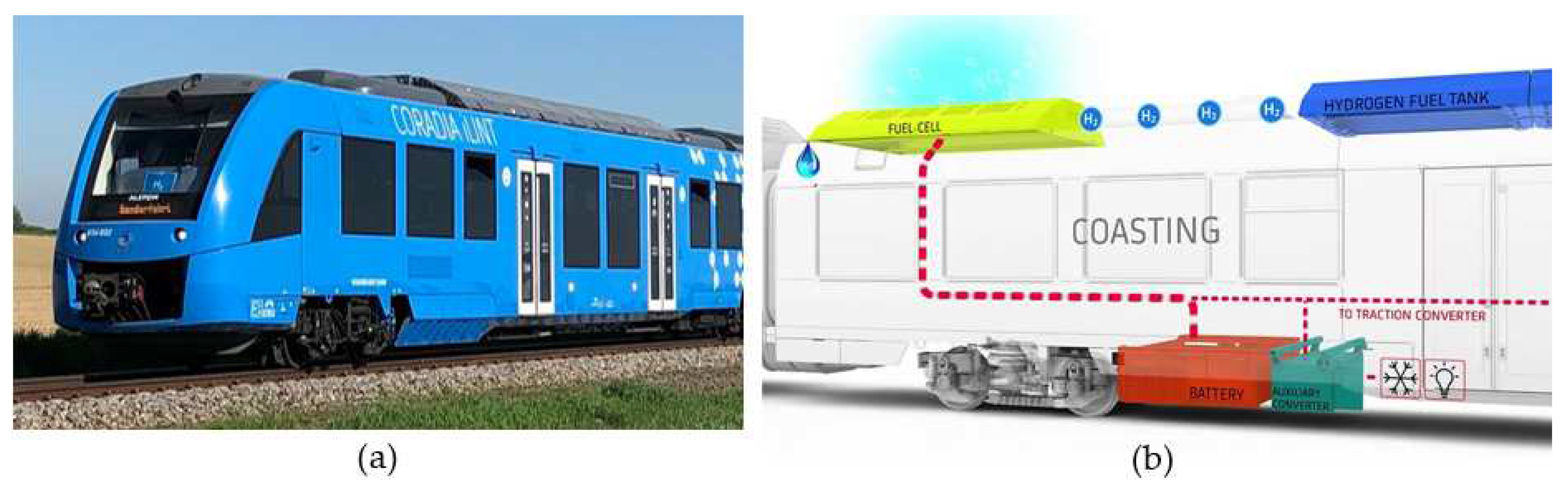
2.5. Railway
2.6. Maritime
2.7. Aviation
3. Manufacturing, Materials and Cost
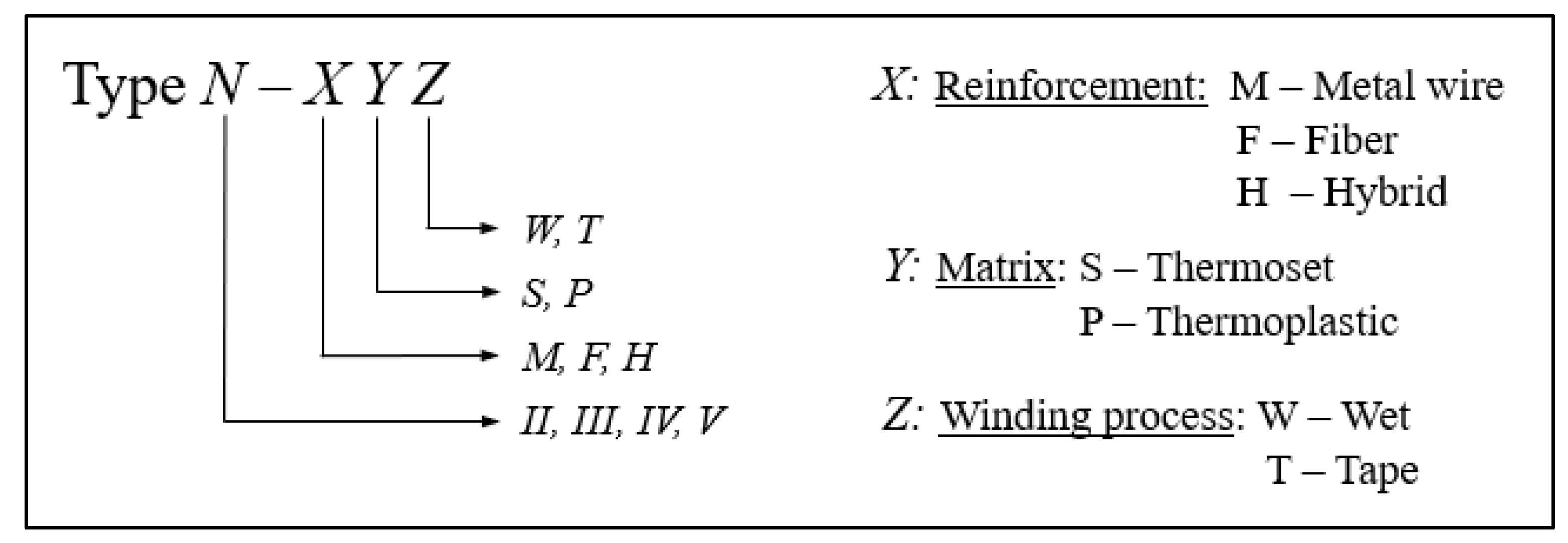
3.1. Industrial Hydrogen Tank-Type Classification
3.2. Winding Methodology: Wet vs. Tape
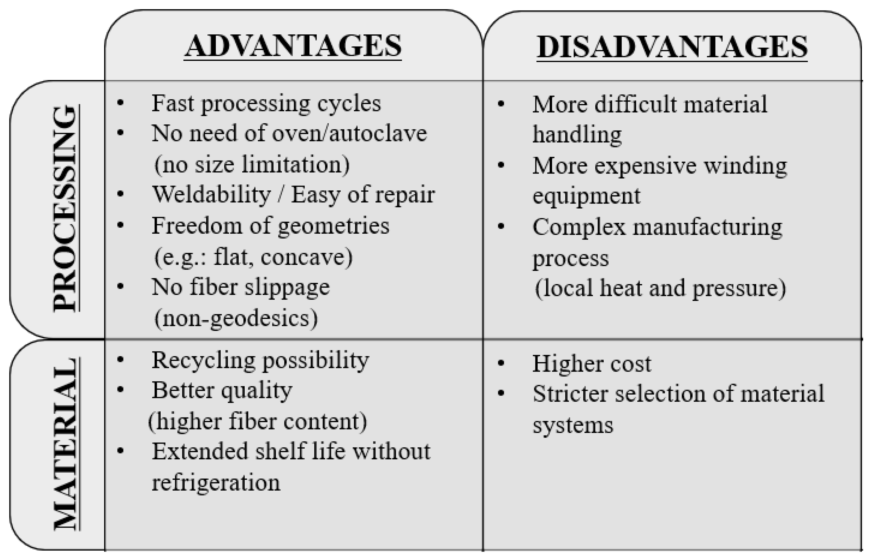
3.3. Conventional vs. Robotic Winding
- -
- Fixed fiber guide/payout eye and flexible mandrel: the robot head rotates the mandrel, and the payout eye unit is fixed at a static position;
- -
- Flexible fiber guide/payout eye and fixed mandrel: the mandrel is held in lathe-type rotation equipment, and the robot head moves the payout eye unit.
3.4. Material Selection
3.4.1. Resin: Thermoset vs. Thermoplastic
- Mechanical recycling: Both thermoplastic and thermoset composites can be crushed into small particles or even fine powders. Afterwards, thermoplastics can be reprocessed several times with the application of heat and pressure. Thermosets can only be employed as fillers or reinforcement for cement, concrete and similar materials.
- Thermal recycling: Applicable for both thermosets and thermoplastics with no substantial discrepancies. It usually consists of the removal of the matrix of composite systems with thermal treatments aiming at fiber recovery.
- Chemical recycling: It removes the matrix by solvolysis or dissolution in a proper solvent, also suitable for both thermosets and thermoplastics. Nevertheless, thermosets usually present higher chemical stability, so fiber recovery is harder. Furthermore, thermoplastics can be dissolved and recovered, while thermoset matrices are generally degraded.
3.4.2. Fibers
3.4.3. Liners
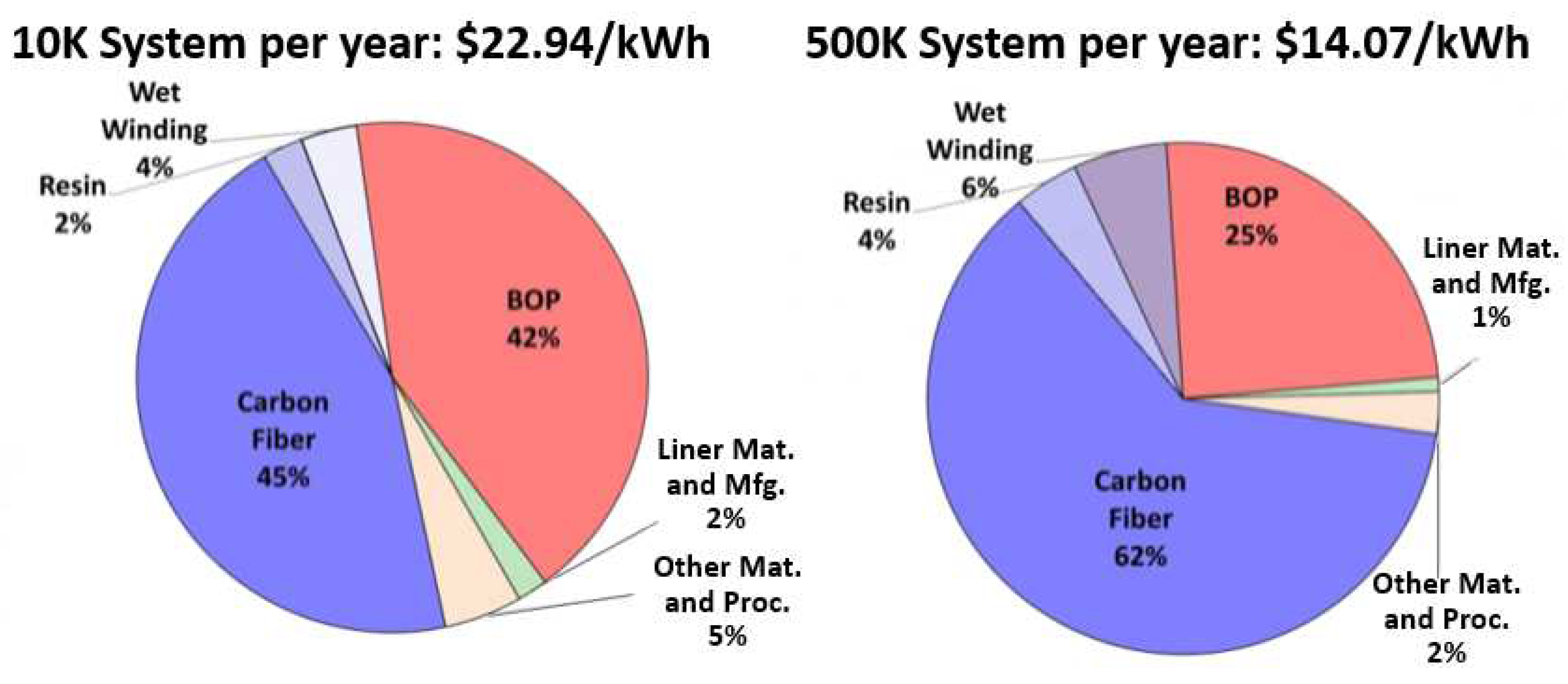
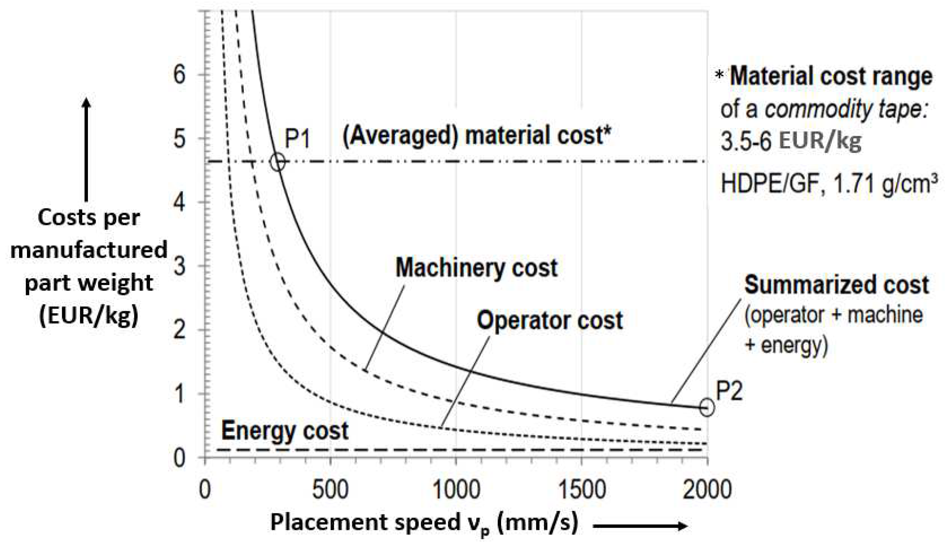
3.5. Cost Analysis
4. Design and Analysis of Hydrogen Tanks
4.1. General
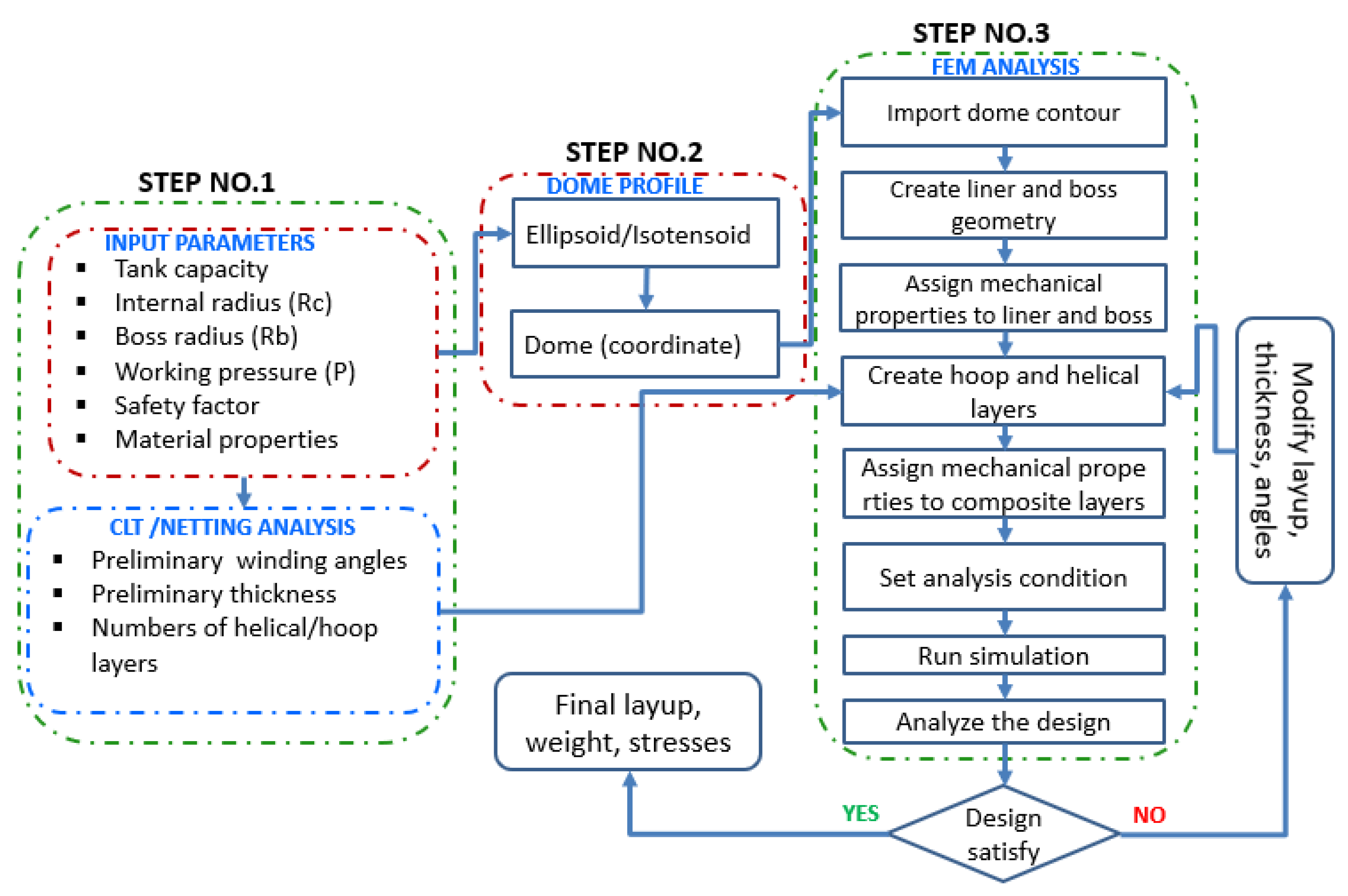
4.2. Design and Analysis Methodology
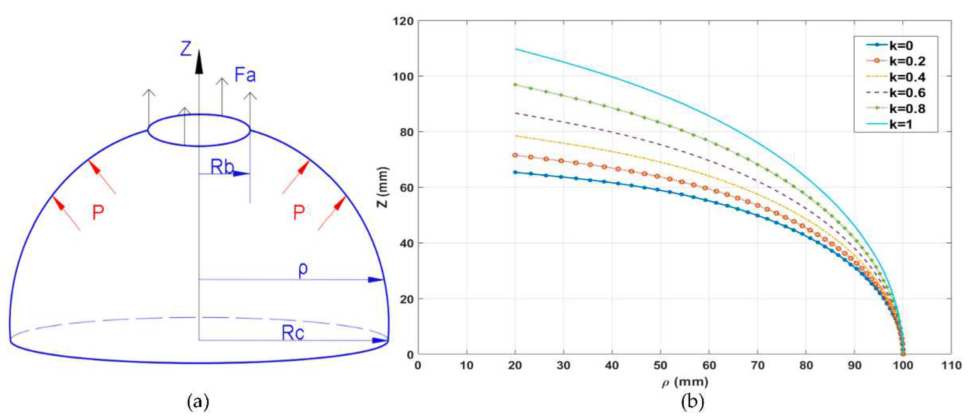
4.3. Design of Dome Profile
- Y = ρ/Rb, with Y ≥ 1;
- Yeq = Rc/Rb;
- Z = z/Rb, with Z > 0;
- R = Fa/πPRc2.
4.4. Finite Element Analysis of Hydrogen Tanks
| Reference | Element | FEA Model |
|---|---|---|
| Hua et al., 2017 [152] | Software: ABAQUS/WCM Axisymmetric 2D elements Element type: CAX4 |  |
| Leh et al., 2015 [162] | Software Model (a): Liner, boss: solid elements Composite layer: shell element Model (b): All solid |  |
| Alcántar et al., 2017 [164] | Software: ANSYS 3D solid element Element type: SOLID191 | 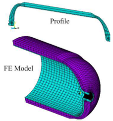 |
| Berro Ramirez et al., 2015 [13] | Model (a): Liner, boss, composite layer: 2D axisymmetric elements Model (b): Liner, boss, composite layer: solid elements | 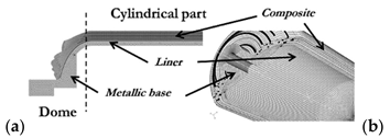 |
| Che et al., 2021 [165] | Software: ABAQUS Axisymmetric section Solid elements Element type:C3D8R | 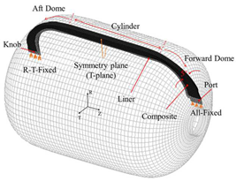 |
4.4.1. Modeling of Winding Layers
4.4.2. Helical Winding on Geodesic Path
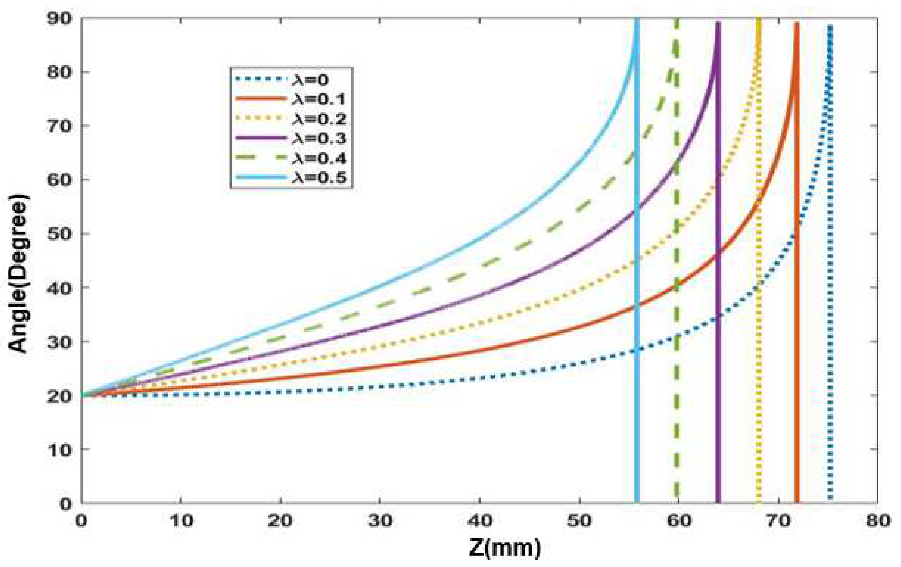
4.4.3. Helical Winding on Non-Geodesic Path
4.5. Working Pressure and Cylinder Dimensions
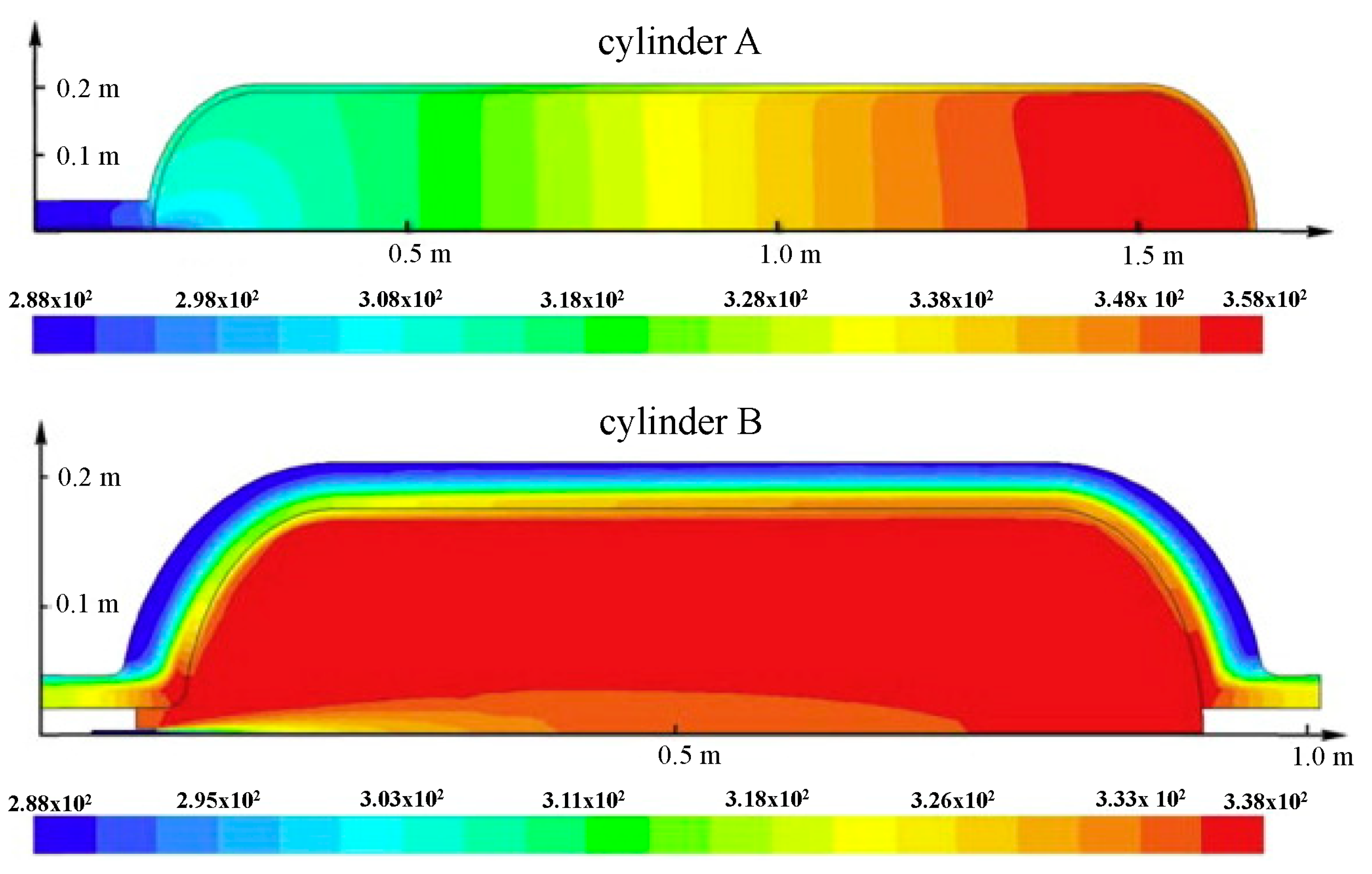
4.5.1. Effect of Working Pressure
4.5.2. Effect of Cylinder Dimensions
5. Testing and Certification
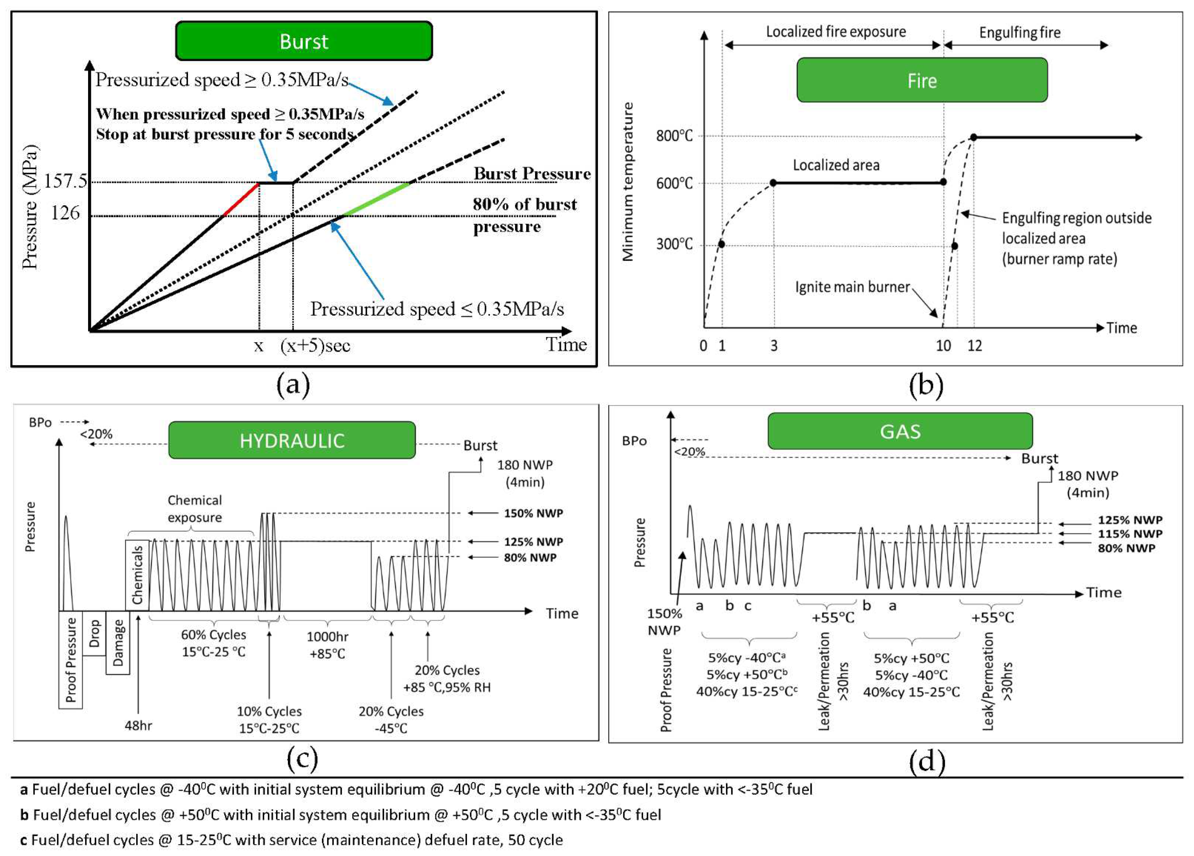
5.1. Hydrostatic Burst Test
5.2. Flame Exposure Test
- Tank is pressurized up to the working pressure (70 MPa);
- Container assembly is positioned 100 mm above the ground;
- Tank is exposed to fire according to the fire-exposed cycle;
- In total, 1-to-10 min fire is applied at localized region (Temp ≤ 900 °C);
- In total, 10-to-12 min engulfing region exposed to fire (Temp ≤ 1100 °C);
- The tank should not burst and should vent by means of a pressure-relief device.
5.3. Performance Durability (Hydraulic/Gas Sequential Test)
6. Conclusions
Author Contributions
Funding
Acknowledgments
Conflicts of Interest
References
- Zawieska, J.; Pieriegud, J. Smart city as a tool for sustainable mobility and transport decarbonisation. Transp. Policy 2018, 63, 39–50. [Google Scholar] [CrossRef]
- Aziz, M. Liquid Hydrogen: A Review on Liquefaction, Storage, Transportation, and Safety. Energies 2021, 14, 5917. [Google Scholar] [CrossRef]
- Zhang, M.; Lv, H.; Kang, H.; Zhou, W.; Zhang, C. A literature review of failure prediction and analysis methods for composite high-pressure hydrogen storage tanks. Int. J. Hydrog. Energy 2019, 44, 25777–25799. [Google Scholar] [CrossRef]
- Quantum Fuel Systems—Scalable Hydrogen Fuel Systems and Infrastructure. Available online: https://www.qtww.com/product/hydrogen/ (accessed on 28 January 2022).
- Hexagon Purus—Hydrogen High Pressure Type 4 Cylinders. Available online: https://hexagonpurus.com/our-solutions/hydrogen-systems/hydrogen-type-4-cylinders (accessed on 28 January 2022).
- ILJIN Hysolus—Hydrogen Mobility. Available online: http://www.composite.co.kr/eng/product/prd_info.jsp?cd=101215 (accessed on 28 January 2022).
- Sources of Greenhouse Gas Emissions. Available online: https://www.epa.gov/ghgemissions/sources-greenhouse-gas-emissions (accessed on 25 January 2022).
- Road Map to a US Hydrogen Economy: Reducing Emissions and Driving Growth Across the Nation. Available online: https://www.fchea.org/us-hydrogen-study (accessed on 25 January 2022).
- Global Greenhouse Gas Emissions by the Transportation Sector. Available online: https://transportgeography.org/contents/chapter4/transportation-and-environment/greenhouse-gas-emissions-transportation/ (accessed on 25 January 2022).
- Tanç, B.; Arat, H.T.; Baltacıoglu, E.; Aydin, K. Overview of the next quarter century vision of hydrogen fuel cell electric vehicles. Int. J. Hydrog. Energy 2019, 44, 10120–10128. [Google Scholar] [CrossRef]
- Rath, R.; Kumar, P.; Mohanty, S.; Nayak, S.K. Recent advances, unsolved deficiencies, and future perspectives of hydrogen fuel cells in transportation and portable sectors. Int. J. Energy Res. 2019, 43, 8931–8955. [Google Scholar] [CrossRef]
- Villalonga, S.; Thomas, C.; Nony, C.; Thiebaud, F.; Geli, M.; Lucas, A.; Knobloch, K.; Maugy, C. Applications of full thermoplastic composite for type IV 70 MPa high pressure vessels. In Proceedings of the 18th International Conference on Composite Materials (ICCM), Jeju Island, Korea, 21–26 August 2011; p. 5. [Google Scholar]
- Berro Ramirez, J.P.; Halm, D.; Grandidier, J.C.; Villalonga, S.; Nony, F. 700 bar type IV high pressure hydrogen storage vessel burst—Simulation and experimental validation. Int. J. Hydrog. Energy 2015, 40, 13183–13192. [Google Scholar] [CrossRef]
- Pépin, J.; Lainé, E.; Grandidier, J.C.; Benoit, G.; Mellier, D.; Weber, M.; Langlois, C. Replication of liner collapse phenomenon observed in hyperbaric type IV hydrogen storage vessel by explosive decompression experiments. Int. J. Hydrog. Energy 2018, 43, 4671–4680. [Google Scholar] [CrossRef]
- Hassan, I.A.; Ramadan, H.S.; Saleh, M.A.; Hissel, D. Hydrogen storage technologies for stationary and mobile applications: Review, analysis and perspectives. Renew. Sustain. Energy Rev. 2021, 149, 111311. [Google Scholar] [CrossRef]
- Barthelemy, H.; Weber, M.; Barbier, F. Hydrogen storage: Recent improvements and industrial perspectives. Int. J. Hydrog. Energy 2017, 42, 7254–7262. [Google Scholar] [CrossRef]
- Ryu, C.; Jung, C.; Bae, J. A study on the analysis of the technology of hydrogen fuel cell vehicle parts—With focus on the patent analysis of co-assignees. Trans. Korean Soc. Automot. Eng. 2020, 28, 227–237. [Google Scholar] [CrossRef]
- Hyundai Nexo High Pressure Hydrogen Tank Safety. Available online: https://en.wikipedia.org/wiki/File:Hyundai_nexo_high_pressure_hydrogen_tank_safety.jpg (accessed on 1 March 2022).
- Hyundai Nexo—The Future Utility Vehicle. Available online: https://www.eurekar.co.uk/articles/2018-07-16/hyundai-nexo-the-future-utility-vehicle (accessed on 1 March 2022).
- Cullen, D.A.; Neyerlin, K.C.; Ahluwalia, R.K.; Mukundan, R.; More, K.L.; Borup, R.L.; Weber, A.Z.; Myers, D.J.; Kusoglu, A. New roads and challenges for fuel cells in heavy-duty transportation. Nat. Energy 2021, 6, 462–474. [Google Scholar] [CrossRef]
- Staffell, I.; Scamman, D.; Velazquez Abad, A.; Balcombe, P.; Dodds, P.E.; Ekins, P.; Shah, N.; Ward, K.R. The role of hydrogen and fuel cells in the global energy system. Energy Environ. Sci. 2019, 12, 463–491. [Google Scholar] [CrossRef] [Green Version]
- Move is on to Ban Diesel Cars from Cities. Available online: https://www.dw.com/en/move-is-on-to-ban-diesel-cars-from-cities/a-42747043 (accessed on 14 February 2022).
- Hydrogen Cars, Vans and Buses. Overview of Flagship Demonstration Initiatives in the Transport Sector. Available online: https://ec.europa.eu/energy/sites/ener/files/documents/3-3_elementenergy_ruf.pdf (accessed on 26 January 2020).
- Gangloff, J.J.; Kast, J.; Morrison, G.; Marcinkoski, J. Design Space Assessment of Hydrogen Storage Onboard Medium and Heavy Duty Fuel Cell Electric Trucks. J. Electrochem. Energy Convers. Storage 2017, 14, 8. [Google Scholar] [CrossRef]
- Alaswad, A.; Baroutaji, A.; Achour, H.; Carton, J.; Al Makky, A.; Olabi, A.G. Developments in fuel cell technologies in the transport sector. Int. J. Hydrog. Energy 2016, 41, 16499–16508. [Google Scholar] [CrossRef] [Green Version]
- Hua, T.; Ahluwalia, R.; Eudy, L.; Singer, G.; Jermer, B.; Asselin-Miller, N.; Wessel, S.; Patterson, T.; Marcinkoski, J. Status of hydrogen fuel cell electric buses worldwide. J. Power Sources 2014, 269, 975–993. [Google Scholar] [CrossRef] [Green Version]
- Clean Urban Transport for Europe. Available online: https://trimis.ec.europa.eu/project/clean-urban-transport-europe (accessed on 28 January 2022).
- National Fuel Cell Bus Program. Available online: https://www.transit.dot.gov/research-innovation/national-fuel-cell-bus-program (accessed on 28 January 2022).
- Stangarone, T. South Korean efforts to transition to a hydrogen economy. Clean Technol. Environ. Policy 2021, 23, 509–516. [Google Scholar] [CrossRef]
- Ajanovic, A.; Glatt, A.; Haas, R. Prospects and impediments for hydrogen fuel cell buses. Energy 2021, 235, 121340. [Google Scholar] [CrossRef]
- Van Hool towards the Launch of the New A330 FC and Exqui City 18 FC. A Fuel Cell Future. Available online: https://www.sustainable-bus.com/news/van-hool-launch-new-a330-fc-and-exqui-fuel-cell-future/ (accessed on 28 January 2022).
- Toyota banks on Olympic Halo for the Humble Bus to Keep Hydrogen Dream Alive. Available online: https://www.reuters.com/article/us-autos-hydrogen-toyota-olympics-fous-idUSKBN1W22VK (accessed on 28 January 2022).
- Hyundai fuel cell bus for operator in Austria. Fuel Cells Bull. 2021, 2021, S1464–S2859.
- Wrightbus Unveiled the First Fuel Cell Double Decker in the World. Available online: https://www.sustainable-bus.com/fuel-cell-bus/streetdeck-fcev-wrightbus-first-fuel-cell-double-decker-bus-in-the-world/ (accessed on 28 January 2022).
- The first VDL Hydrogen Bus Deployed by Connexxion. With a Trailer Housing H2 Technology. Available online: https://www.sustainable-bus.com/news/vdl-hydrogen-bus-connexxion/ (accessed on 28 January 2022).
- Reddi, K.; Mintz, M.; Elgowainy, A.; Sutherland, E. Challenges and Opportunities of Hydrogen Delivery via Pipeline, Tube-Trailer, LIQUID Tanker and Methanation-Natural Gas Grid. Hydrog. Sci. Eng. Mater. Process. Syst. Technol. 2016, 2, 849–873. [Google Scholar] [CrossRef]
- Reddi, K.; Elgowainy, A.; Sutherland, E. Hydrogen refueling station compression and storage optimization with tube-trailer deliveries. Int. J. Hydrog. Energy 2014, 39, 19169–19181. [Google Scholar] [CrossRef] [Green Version]
- Elgowainy, A.; Reddi, K.; Sutherland, E.; Joseck, F. Tube-trailer consolidation strategy for reducing hydrogen refueling station costs. Int. J. Hydrog. Energy 2014, 39, 20197–20206. [Google Scholar] [CrossRef] [Green Version]
- Compressed Gaseous Hydrogen. Available online: https://fuelcellbuses.eu/wiki/concept-hydrogen-refueling-station/tube-trailer-gaseous-hydrogen-%E2%80%9Ctrucked-in%E2%80%9D (accessed on 11 February 2022).
- Air Products—Tube Trailers. Available online: https://www.airproducts.co.uk/supply-modes/tube-trailers (accessed on 14 February 2022).
- Advanced Hydrogen Fueling Station Supply: Tube Trailers. Available online: https://www.osti.gov/biblio/1469970 (accessed on 14 February 2022).
- Final Report Summary—HYTEC (Hydrogen Transport in European Cities). Available online: https://cordis.europa.eu/project/id/278727/reporting (accessed on 14 February 2022).
- Iljin Hysolus, Korea’s Leading Composite Tank Producer for Hydrogen Storage, sets IPO for Sept. 3. Available online: https://www.compositesworld.com/news/iljin-hysolus-koreas-leading-composite-tank-producer-for-hydrogen-storage-sets-ipo-for-sept-3 (accessed on 14 February 2022).
- Hydrogen’s Economy Artery: Iljin Hysolus Launches Type 4 Hydrogen Tube Trailer. Available online: https://fuelcellsworks.com/subscribers/hydrogens-economy-artery-iljin-hisolus-launches-type-4-hydrogen-tube-trailer/ (accessed on 14 February 2022).
- Azuma, M.; Oimatsu, K.; Oyama, S.; Kamiya, S.; Igashira, K.; Takemura, T.; Takai, Y. Safety design of compressed hydrogen trailers with composite cylinders. Int. J. Hydrog. Energy 2014, 39, 20420–20425. [Google Scholar] [CrossRef]
- High-Pressure Hydrogen Gas Trailer—Japan’s First Composite Tank. Available online: https://global.kawasaki.com/en/corp/rd/magazine/176/pdf/n176en21.pdf (accessed on 14 January 2022).
- Reddi, K.; Mintz, M.; Elgowainy, A.; Sutherland, E. Building a Hydrogen Infrastructure in the United States; Elsevier Ltd.: Amsterdam, The Netherlands, 2016; ISBN 9781782423645. [Google Scholar]
- Xiao, L.; Chen, J.; Wu, Y.; Zhang, W.; Ye, J.; Shao, S.; Xie, J. Effects of pressure levels in three-cascade storage system on the overall energy consumption in the hydrogen refueling station. Int. J. Hydrog. Energy 2021, 46, 31334–31345. [Google Scholar] [CrossRef]
- Farzaneh-Gord, M.; Deymi-Dashtebayaz, M.; Rahbari, H.R.; Niazmand, H. Effects of storage types and conditions on com-pressed hydrogen fuelling stations performance. Int. J. Hydrog. Energy 2012, 37, 3500–3509. [Google Scholar] [CrossRef]
- Tian, Z.; Lv, H.; Zhou, W.; Zhang, C.; He, P. Review on equipment configuration and operation process optimization of hydrogen refueling station. Int. J. Hydrog. Energy 2022, 47, 3033–3053. [Google Scholar] [CrossRef]
- Parks, G.; Boyd, R.; Cornish, J.; Remick, R. Hydrogen Station Compression, Storage, and Dispensing Technical Status and Costs: Systems Integration; National Renewable Energy Lab: Golden, CO, USA, 2014. [CrossRef]
- Siddiqui, O.; Dincer, I. A Review on Fuel Cell-Based Locomotive Powering Options for Sustainable Transportation. Arab. J. Sci. Eng. 2019, 44, 677–693. [Google Scholar] [CrossRef]
- Study on the Use of Fuel Cells and Hydrogen in the Railway Environment. Available online: https://shift2rail.org/publications/study-on-the-use-of-fuel-cells-and-hydrogen-in-the-railway-environment/ (accessed on 26 January 2022).
- Miller, A.R.; Van den Berg, G.; Barnes, D.L.; Eisele, R.I.; Tanner, D.M.; Vallely, J.M.; Lassiter, D.A. Fuel cell technology in underground mining. In Proceedings of the 5th International Platinum Conference, Sun City, South Africa, 18–21 September 2012; pp. 533–546. [Google Scholar]
- Development of the World’s First Fuel Cell Hybrid Railcar. Available online: https://www.jreast.co.jp/e/press/20060401/ (accessed on 28 January 2022).
- Hoffrichter, A. Hydrogen-rail (hydrail) development. In H2@Rail Workshop; Michigan State University: Lansing, MI, USA, 2019. [Google Scholar]
- Alstom’s Coradia iLint Hydrogen Train Runs for the First Time in Sweden. Available online: https://www.alstom.com/press-releases-news/2021/8/alstoms-coradia-ilint-hydrogen-train-runs-first-time-sweden (accessed on 31 January 2022).
- JR East planning next-generation fuel cell train. Fuel Cells Bull. 2019, 2019, s1464–s2859.
- Ballard Receives Order for Fuel Cell Modules to Power Trial Operation of Siemens Mireo Plus H Train. Available online: https://www.ballard.com/about-ballard/newsroom/news-releases/2021/07/15/ballard-receives-order-for-fuel-cell-modules-to-power-trial-operation-of-siemens-mireo-plus-h-train (accessed on 31 January 2022).
- Stadler hydrogen fuel cell train for California. Fuel Cells Bull. 2019, 2019, s1464–s2859.
- TIG/m, LLC Delivers Third Hydrogen/Hybrid Streetcar to Aruba in Island’s Transition to 100% Sustainability. Available online: https://patch.com/california/northridge/tigm-llc-delivers-third-hydrogenhybrid-streetcar-aruba-islands-transition-100-sustainability (accessed on 31 January 2022).
- Ulsan and Hyundai Rotem Agree Hydrogen Tram Project. Available online: https://www.railjournal.com/technology/ulsan-and-hyundai-rotem-agree-hydrogen-tram-project/ (accessed on 26 January 2022).
- H2 On-Board Storage Options for Rail Vehicles. Available online: https://elib.dlr.de/186537/1/EHEC_2022_FCH2Rail_Hydrogen%20on-board%20storage%20options%20for%20rail%20vehicles_B%C3%B6hm_final.pdf (accessed on 9 June 2022).
- Boehm, M. Hydrogen on-board storage options for rail vehicles. In Proceedings of the European Hydrogen Energy Conference, Madrid, Spain, 18–20 May 2022; p. 2. [Google Scholar]
- The UK’s First Hydrogen Train is Unveiled, Developed with Alternative Fuel Expertise from Luxfer. Available online: https://www.luxfer.com/press/2019/ukand-s-1st-hydrogen-train-features-luxfer-alt-fuel-technology.asp (accessed on 9 June 2022).
- Alstom’s Hydrogen Train Coradia iLint Completes Successful Tests in the Netherlands. Available online: https://www.alstom.com/press-releases-news/2020/3/alstoms-hydrogen-train-coradia-ilint-completes-successful-tests (accessed on 31 January 2022).
- The World’s First Hydrogen-Powered Commuter Train. Available online: https://danieldonatelli.wixsite.com/energy-power-gas/train-rail-industry-news (accessed on 31 January 2022).
- Tronstad, T.; Høgmoen, Å.H.; Haugom, G.P.; Langfeldt, L. Study on the Use of Fuel Cells in Shipping; European Maritime Safety Agency: Lisbon, Portugal, 2017. [Google Scholar]
- Li, F.; Yuan, Y.; Yan, X.; Malekian, R.; Li, Z. A study on a numerical simulation of the leakage and diffusion of hydrogen in a fuel cell ship. Renew. Sustain. Energy Rev. 2018, 97, 177–185. [Google Scholar] [CrossRef] [Green Version]
- Xing, H.; Stuart, C.; Spence, S.; Chen, H. Fuel cell power systems for maritime applications: Progress and perspectives. Sustainability 2021, 13, 1213. [Google Scholar] [CrossRef]
- Mendez, A.; Leo, T.J.; Herreros, M.A. Current state of technology of fuel cell power systems for autonomous underwater vehicles. Energies 2014, 7, 4676–4693. [Google Scholar] [CrossRef] [Green Version]
- Raugel, E.; Rigaud, V.; Lakeman, C. Sea experiment of a survey AUV powered by a fuel cell system. In Proceedings of the 2010 IEEE/OES Autonomous Underwater Vehicles, Monterey, CA, USA, 1–3 September 2010; p. 3. [Google Scholar]
- AREVA Tests Fuel Cell for Deep-Sea Application. Available online: https://www.sa.areva.com/EN/news-7867/areva-tests-fuel-cell-for-deepsea-applications.html (accessed on 26 January 2022).
- Hydrogen Fuel Cells Could Power the Navy’s Future Robotic Submarine. Available online: https://defense-update.com/20160628_uuv_power.html (accessed on 26 January 2022).
- Hydrogen-Powered Autonomous Freight Submarine among Winners of £23m UK R&D Grants. Available online: https://www.rechargenews.com/technology/hydrogen-powered-autonomous-freight-submarine-among-winners-of-23m-uk-r-d-grants/2-1-1068054 (accessed on 26 January 2022).
- Why Germany’s New Super Stealth Submarines Could Take on Any Navy. Available online: https://nationalinterest.org/blog/the-buzz/why-germanys-new-super-stealth-submarines-could-take-any-21021 (accessed on 26 January 2022).
- Commitment to Fly Net Zero. Available online: https://aviationbenefits.org/FlyNetZero (accessed on 26 January 2022).
- Baroutaji, A.; Wilberforce, T.; Ramadan, M.; Olabi, A.G. Comprehensive investigation on hydrogen and fuel cell technology in the aviation and aerospace sectors. Renew. Sustain. Energy Rev. 2019, 106, 31–40. [Google Scholar] [CrossRef] [Green Version]
- Koehler, T. A green machine. Boeing Frontier, 1 May 2008; 44. [Google Scholar]
- Lapeña-Rey, N.; Mosquera, J.; Bataller, E.; Ortí, F. First fuel-cell manned aircraft. J. Aircr. 2010, 47, 1825–1835. [Google Scholar] [CrossRef]
- Renouard-Vallet, G.; Saballus, M.; Schmithals, G.; Schirmer, J.; Kallo, J.; Friedrich, K.A. Improving the environmental impact of civil aircraft by fuel cell technology: Concepts and technological progress. Energy Environ. Sci. 2010, 3, 1458–1468. [Google Scholar] [CrossRef]
- Correa, G.; Santarelli, M.; Borello, F.; Cestino, E.; Romeo, G. Flight test validation of the dynamic model of a fuel cell system for ultra-light aircraft. Proc. Inst. Mech. Eng. Part G J. Aerosp. Eng. 2015, 229, 917–932. [Google Scholar] [CrossRef]
- Kallo, J. DLR leads HY4 project for four-seater fuel cell aircraft. Fuel Cells Bull. 2015, 2015, 13. [Google Scholar] [CrossRef]
- ZeroAvia Completes Milestone Hydrogen Fuel Cell Flight. Available online: https://www.flyingmag.com/zeroavia-completes-hydrogen-fuel-cell-flight/ (accessed on 31 January 2022).
- Hyflyer Projects—Hyflyer II—Project Overview. Available online: https://www.emec.org.uk/projects/hydrogen-projects/hyflyer/ (accessed on 31 January 2022).
- Liebherr and GM to Develop HYDROTEC Fuel Cell-Based Electrical Power Generation System for Aerospace Application. Available online: https://www.liebherr.com/en/int/latest-news/news-press-releases/detail/liebherr-and-gm-to-develop-hydrotec-fuel-cell-based-electrical-power-generation-system-for-aerospace-application.html (accessed on 31 January 2022).
- ZEROe—Towards the World’s First Zero-Emission Commercial Aircraft. Available online: https://www.airbus.com/en/innovation/zero-emission/hydrogen/zeroe (accessed on 31 January 2022).
- González-Espasandín, Ó.; Leo, T.J.; Navarro-Arévalo, E. Fuel cells: A real option for unmanned aerial vehicles propulsion. Sci. World J. 2014, 2014, 12. [Google Scholar] [CrossRef] [Green Version]
- Gong, A.; Verstraete, D. Fuel cell propulsion in small fixed-wing unmanned aerial vehicles: Current status and research needs. Int. J. Hydrog. Energy 2017, 42, 21311–21333. [Google Scholar] [CrossRef]
- Wang, B.; Zhao, D.; Li, W.; Wang, Z.; Huang, Y.; You, Y.; Becker, S. Current technologies and challenges of applying fuel cell hybrid propulsion systems in unmanned aerial vehicles. Prog. Aerosp. Sci. 2020, 116, 22. [Google Scholar] [CrossRef]
- Pan, Z.F.; An, L.; Wen, C.Y. Recent advances in fuel cells based propulsion systems for unmanned aerial vehicles. Appl. Energy 2019, 240, 473–485. [Google Scholar] [CrossRef]
- Apeland, J.; Pavlou, D.; Hemmingsen, T. Suitability analysis of implementing a fuel cell on a multirotor drone. J. Aerosp. Technol. Manag. 2020, 12, 1–14. [Google Scholar] [CrossRef]
- Li, M.; Bai, Y.; Zhang, C.; Song, Y.; Jiang, S.; Grouset, D.; Zhang, M. Review on the research of hydrogen storage system fast refueling in fuel cell vehicle. Int. J. Hydrog. Energy 2019, 44, 10677–10693. [Google Scholar] [CrossRef] [Green Version]
- Rivard, E.; Trudeau, M.; Zaghib, K. Hydrogen storage for mobility: A review. Materials 2019, 12, 1973. [Google Scholar] [CrossRef] [PubMed] [Green Version]
- About tank Types. Available online: https://www.infinitecomposites.com/composite-pressure-vessel-resources (accessed on 9 February 2022).
- Hanwha Solutions Developing Type 5 Hydrogen Tank. Available online: http://www.thelec.net/news/articleView.html?idxno=3450 (accessed on 29 May 2022).
- First Type 5? Available online: https://www.infinitecomposites.com/about-us#Contact_Sec (accessed on 29 May 2022).
- Mallick, K.; Cronin, J.; Fabian, P.; Tupper, M. Microcrack resistant polymers enabling lightweight composite hydrogen storage vessels. In Materials Challenges in Alternative and Renewable Energy; Wicks, G., Simon, J., Zidan, R., Lara-Curzio, E., Adams, T., Zayas, J., Eds.; The American Ceramic Society: Columbus, OH, USA, 2011; pp. 91–98. [Google Scholar] [CrossRef]
- From Space Travel to Everyday Transport—Hydrogen as a Fuel for New Energy Systems. Available online: https://epub.uni-bayreuth.de/5803/1/spektrum-2020-1-hydrogen_EN%281%29.pdf (accessed on 29 May 2022).
- Hübner, F.; Brückner, A.; Dickhut, T.; Altstädt, V.; Rios de Anda, A.; Ruckdäschel, H. Low temperature fatigue crack propagation in toughened epoxy resins aimed for filament winding of type V composite pressure vessels. Polym. Test. 2021, 102, 107323. [Google Scholar] [CrossRef]
- All-Composite Type V Linerless Pressure Vessel. Available online: https://ctd-materials.com/experience/linerless-tanks/ (accessed on 29 May 2022).
- Munro, M. Review of manufacturing of fiber composite components by filament winding. Polym. Compos. 1988, 9, 352–359. [Google Scholar] [CrossRef]
- Sofi, T.; Neunkirchen, S.; Schledjewski, R. Path calculation, technology and opportunities in dry fiber winding: A review. Adv. Manuf. Polym. Compos. Sci. 2018, 4, 57–72. [Google Scholar] [CrossRef]
- Mack, J.; Schledjewski, R. Filament winding process in thermoplastics. In Manufacturing Techniques for Polymer Matrix Composites (PMCs); Suresh, G., Advani, K.-T.H., Eds.; Woodhead Publishing Limited: Sawston, UK, 2012; pp. 182–208. [Google Scholar]
- Funck, R.; Neitzel, M. Improved thermoplastic tape winding using laser or direct-flame heating. Compos. Manuf. 1995, 6, 189–192. [Google Scholar] [CrossRef]
- DuVall, F.W. Cost comparisons of wet filament winding versus prepreg filament winding for Type II and Type IV CNG cylinders. In Proceedings of the 12th International Conference on Composite Materials, Paris, France, 5–9 July 1999; p. 9. [Google Scholar]
- Weisberg, A.; Aceves, S.M. The potential of dry winding for rapid, inexpensive manufacture of composite overwrapped pressure vessels. Int. J. Hydrog. Energy 2015, 40, 4207–4211. [Google Scholar] [CrossRef] [Green Version]
- Cui, Y.Q.; Yin, Z.W.; Li, H.L. Influence of tension in T300/epoxy prepreg winding process on the performance of the bearing composites. J. Reinf. Plast. Compos. 2017, 36, 1099–1115. [Google Scholar] [CrossRef]
- Chang, C.; Han, Z.; Li, X.; Sun, S.; Qin, J.; Fu, H. A non-geodesic trajectory design method and its post-processing for robotic filament winding of composite tee pipes. Materials 2021, 14, 847. [Google Scholar] [CrossRef]
- Kang, C.; Shi, Y.; Deng, B.; Yu, T.; Sun, P. Determination of Residual Stress and Design of Process Parameters for Composite Cylinder in Filament Winding. Adv. Mater. Sci. Eng. 2018, 2018, 1342. [Google Scholar] [CrossRef] [Green Version]
- Henriquez, R.G.; Mertiny, P. Filament winding applications. In Comprehensive Composite Materials II; Elsevier Ltd.: Amsterdam, The Netherlands, 2018; Volume 3, pp. 556–577. ISBN 9780081005330. [Google Scholar]
- Sorrentino, L.; Anamateros, E.; Bellini, C.; Carrino, L.; Corcione, G.; Leone, A.; Paris, G. Robotic filament winding: An innovative technology to manufacture complex shape structural parts. Compos. Struct. 2019, 220, 699–707. [Google Scholar] [CrossRef]
- The Filament Winding Process. Available online: https://www.cadfil.com/filamentwindingprocess.html (accessed on 31 January 2022).
- Cygnet Texkimp Launches World-First Robotic 3D Winding Machine at JEC. Available online: https://cygnet-texkimp.com/cygnet-texkimp-launches-world-first-robotic-3d-winding-machine-at-jec/ (accessed on 31 January 2022).
- The Advanced Manufacturing Center with Boeing—Composites Group—Robotic Filament Winding Capability. Available online: https://www.amrc.co.uk/files/wp_images/Robotic-Filament-Winding-Capability-PDF2.pdf (accessed on 31 January 2022).
- Peters, S.T. Filament Winding—Introduction and Overview. In Composites Filament Winding, 1st ed.; ASM International: Materials Park, OH, USA, 2011; ISBN 9781615037223. [Google Scholar]
- Minsch, N.; Herrmann, F.H.; Gereke, T.; Nocke, A.; Cherif, C. Analysis of filament winding processes and potential equipment technologies. In Proceedings of the 1st CIRP Conference on Composite Materials Parts Manufacturing (CIRP-CCMPM 2017), Karlsruhe, Germany, 8–9 June 2017; pp. 125–130. [Google Scholar]
- Quanjin, M.; Rejab, M.R.M.; Kumar, N.M.; Merzuki, M.N.M. Robotic Filament Winding Technique (RFWT) in Industrial Application: A Review of State of the Art and Future Perspectives. Int. Res. J. Eng. Technol. 2018, 5, 1668–1676. [Google Scholar]
- Filament Winding, Reinvented. Available online: https://www.compositesworld.com/articles/filament-winding-reinvented (accessed on 27 January 2022).
- CAMX 2021 Exhibit Preview: Mikrosam. Available online: https://www.compositesworld.com/products/camx-2021-exhibit-preview-mikrosam (accessed on 27 January 2022).
- Minsch, N.; Müller, M.; Gereke, T.; Nocke, A.; Cherif, C. Novel fully automated 3D coreless filament winding technology. J. Compos. Mater. 2018, 52, 3001–3013. [Google Scholar] [CrossRef]
- Dionoro, G.; Pilloni, M.T.; Romano, D. Process innovation in composite manufacturing by filament winding: A managerial assessment. High Perform. Struct. Mater. 2004, 7, 23–35. [Google Scholar]
- Automated Filament Winding Line for LPG, CNG, Hydrogen and Other Types of High Pressure Vessel. Available online: https://archive.mikrosam.com/new/article/en/automated-filament-winding-line-for-lpg-cng-hydrogen-and-other-types-of-high-pressure-vessels/index.html (accessed on 27 January 2022).
- Tomas Aström, B. Thermoplastic composites manufacturing. In ASM Handbook; Miracle, D.B., Donaldson, S.L., Eds.; ASM International: Almere, The Netherlands, 2001; Volume 21, pp. 570–578. [Google Scholar]
- Boon, Y.D.; Joshi, S.C.; Bhudolia, S.K. Filament Winding and Automated Fiber Placement with In Situ Consolidation for Fiber Reinforced Thermoplastic Polymer Composites. Polymers 2021, 13, 1951. [Google Scholar] [CrossRef]
- Elium® Resin for Composite Hydrogen Tanks. Available online: https://www.arkema.com/global/en/products/product-finder/product/incubator/elium/elium-resin-for-composite-hydrogen-tanks/#otherDocAnchor (accessed on 31 January 2022).
- Henninger, F.; Friedrich, K. Thermoplastic filament winding with online-impregnation. Part A: Process technology and operating efficiency. Compos. Part A Appl. Sci. Manuf. 2002, 33, 1479–1486. [Google Scholar] [CrossRef]
- Pegoretti, A. Advanced Industrial and Engineering Polymer Research Towards sustainable structural composites: A review on the recycling of continuous-fiber-reinforced thermoplastics. Adv. Ind. Eng. Polym. Res. 2021, 4, 105–115. [Google Scholar] [CrossRef]
- Nony, F.; Thomas, C.; Villalonga, S.; Magnier, C. Research and achievements on carbon fiber reinforced thermoplastic composites for high pressure storage. In Proceedings of the ASME 2011 Pressure Vessels & Piping Division Conference, Baltimore, MD, USA, 17–21 July 2011; pp. 1–7. [Google Scholar]
- Emerson, D.; Ruby, M.; Almond, D.; Turner, M.; Clarke, A. All-Thermoplastic Composite Hydrogen Storage Cylinders for Fuel-Cell Powered Passenger Vehicles. In Proceedings of the SPE Automotive Composites Conference & Exhibition, Novi, MI, USA, 9–11 September 2014; pp. 1–16. [Google Scholar]
- Thermoplastic Composite Pressure Vessels for FCVs. Available online: https://www.compositesworld.com/articles/thermoplastic-composite-pressure-vessels-for-fcvs (accessed on 26 January 2022).
- Thermoplastic Hydrogen Tanks Optimised and Recyclable. Available online: https://thor-fch2.eu/ (accessed on 26 January 2022).
- Kessler, E.; Gadow, R.; Straub, J. Basalt, glass and carbon fibers and their fiber reinforced polymer composites under thermal and mechanical load. AIMS Mater. Sci. 2016, 3, 1561–1576. [Google Scholar] [CrossRef]
- Kangal, S.; Kartav, O.; Tanoğlu, M.; Aktaş, E.; Artem, H.S. Investigation of interlayer hybridization effect on burst pressure performance of composite overwrapped pressure vessels with load-sharing metallic liner. J. Compos. Mater. 2020, 54, 961–980. [Google Scholar] [CrossRef]
- Afrathim, A.; Karuppanan, S.; Patil, S.S. Burst strength analysis of thin composite pressure vessels. Mater. Today Proc. 2021, 44, 3115–3120. [Google Scholar] [CrossRef]
- Sirosh, N. Fuels—Hydrogen storage. In Encyclopedia of Electrochemical Power Sources; Garche, J., Ed.; Elsevier Ltd.: Amsterdam, The Netherlands, 2009; pp. 414–420. [Google Scholar]
- Artemenko, S.E. Polymer composite material made from carbon, basalt, and glass fibres. Structure and properties. Fibre Chem. 2003, 35, 43–46. [Google Scholar]
- Pavlovski, D.; Mislavsky, B.; Antonov, A. CNG cylinder manufacturers test basalt fibre. Reinf. Plast. 2007, 51, 36–38. [Google Scholar] [CrossRef]
- Generation 1—Hydrogen Ground Storage. Available online: https://wiretough.com/hydrogen-ground-storage/ (accessed on 31 January 2022).
- Foorginezhad, S.; Mohseni-Dargah, M.; Falahati, Z.; Abbassi, R. Sensing advancement towards safety assessment of hydrogen fuel cell vehicles. J. Power Sources 2021, 489, 229450. [Google Scholar] [CrossRef]
- Pepin, J.; Lainé, E.; Grandidier, J.C.; Castagnet, S.; Blanc-vannet, P.; Papin, P.; Weber, M. Determination of key parameters responsible for polymeric liner collapse in hyperbaric type IV hydrogen storage vessels. Int. J. Hydrog. Energy 2018, 43, 16386–16399. [Google Scholar] [CrossRef]
- Fujiwara, H.; Ono, H.; Onoue, K.; Nishimura, S. High-pressure gaseous hydrogen permeation test method -property of polymeric materials for high-pressure hydrogen devices. Int. J. Hydrog. Energy 2020, 45, 29082–29094. [Google Scholar] [CrossRef]
- Sharma, P.; Bera, T.; Semwal, K.; Badhe, R.M.; Sharma, A.; Ramakumar, S.S.V.; Neogi, S. Theoretical analysis of design of filament wound type 3 composite cylinder for the storage of compressed hydrogen gas. Int. J. Hydrog. Energy 2020, 45, 25386–25397. [Google Scholar] [CrossRef]
- Weiler, T. Thermal Skin Effect in Laser-Assisted Tape Placement of Thermoplastic Composites. Ph.D. Thesis, RWTH Aachen University, Aachen, Germany, 2019. [Google Scholar]
- James, B.D.; Houchins, C.; Huya-Kouadio, J.M.; Desantis, D.A. Final Report: Hydrogen Storage System Cost Analysis; Strategic Analysis Inc.: Arlington, VA, USA, 2016. [Google Scholar]
- Achieving Hydrogen Storage Goals through High Strength Glass Fiber. Available online: https://www.hydrogen.energy.gov/pdfs/progress16/iv_d_6_li_2016.pdf (accessed on 8 February 2022).
- Onboard Type IV Compressed Hydrogen Storage Systems—Current Performance and Cost. Available online: https://www.hydrogen.energy.gov/pdfs/13010_onboard_storage_performance_cost.pdf (accessed on 24 April 2022).
- Johnson, K.; Veenstra, M.J.; Gotthold, D.; Simmons, K.; Alvine, K.; Hobein, B.; Houston, D.; Newhouse, N.; Yeggy, B.; Vaipan, A.; et al. Advancements and Opportunities for On-Board 700 Bar Compressed Hydrogen Tanks in the Progression Towards the Commercialization of Fuel Cell Vehicles. SAE Int. J. Altern. Powertrains 2017, 6, 201–218. [Google Scholar] [CrossRef]
- Kabir, M.Z. Finite element analysis of composite pressure vessels with a load sharing metallic liner. Compos. Struct. 2000, 49, 247–255. [Google Scholar] [CrossRef]
- Park, J.S.; Hong, C.S.; Kim, C.G.; Kim, C.U. Analysis of filament wound composite structures considering the change of winding angles through the thickness direction. Compos. Struct. 2002, 55, 63–71. [Google Scholar] [CrossRef]
- Roh, H.S.; Hua, T.Q.; Ahluwalia, R.K. Optimization of carbon fiber usage in Type 4 hydrogen storage tanks for fuel cell automobiles. Int. J. Hydrog. Energy 2013, 38, 12795–12802. [Google Scholar] [CrossRef]
- Hua, T.Q.; Roh, H.S.; Ahluwalia, R.K. Performance assessment of 700-bar compressed hydrogen storage for light duty fuel cell vehicles. Int. J. Hydrog. Energy 2017, 42, 25121–25129. [Google Scholar] [CrossRef]
- Daghia, F.; Baranger, E.; Tran, D.T.; Pichon, P. A hierarchy of models for the design of composite pressure vessels. Compos. Struct. 2020, 235, 111809. [Google Scholar] [CrossRef] [Green Version]
- Peters, S.T. Composites Filament Winding, 1st ed.; ASM International: Materials Park, OH, USA, 2011; ISBN 9781615037223. [Google Scholar]
- Vasiliev, V.V.; Krikanov, A.A.; Razin, A.F. New generation of filament-wound composite pressure vessels for commercial applications. Compos. Struct. 2003, 62, 449–459. [Google Scholar] [CrossRef]
- Vita, A.; Borriello, S.; Landi, D.; Scafa, M.; Germani, M. A Methodological Approach for the Design of Composite Tanks Produced by Filament Winding. In Proceedings of the CAD’19, Singapore, 24–26 June 2019; pp. 288–292. [Google Scholar]
- Koussios, S. Design of cylindrical composite pressure vessels: Integral optimisation. In Proceedings of the ICCM-17 International Conferences on Composite Materials, Edinburgh, Scotland, UK, 27–31 July 2009. [Google Scholar]
- Zhou, J.; Chen, J.; Zheng, Y.; Wang, Z.; An, Q. Dome shape optimization of filament-wound composite pressure vessels based on hyperelliptic functions considering both geodesic and non-geodesic winding patterns. J. Compos. Mater. 2017, 51, 1961–1969. [Google Scholar] [CrossRef]
- Liang, C.C.; Chen, H.W.; Wang, C.H. Optimum design of dome contour for filament-wound composite pressure vessels based on a shape factor. Compos. Struct. 2002, 58, 469–482. [Google Scholar] [CrossRef]
- Wound Composite Modeler for Abaqus User’s Manual; Simulia: Johnston, RI, USA, 2007.
- WoundSIM—Integrated Intelligence for Composite Pressure Vessels Design and Simulation. Available online: https://www.svertical.com/woundsim (accessed on 1 March 2022).
- Leh, D.; Saffré, P.; Francescato, P.; Arrieux, R.; Villalonga, S. A progressive failure analysis of a 700-bar type IV hydrogen composite pressure vessel. Int. J. Hydrog. Energy 2015, 40, 13206–13214. [Google Scholar] [CrossRef]
- Leh, D.; Magneville, B.; Saffré, P.; Francescato, P.; Arrieux, R.; Villalonga, S. Optimisation of 700 bar type IV hydrogen pressure vessel considering composite damage and dome multi-sequencing. Int. J. Hydrog. Energy 2015, 40, 13215–13230. [Google Scholar] [CrossRef]
- Alcántar, V.; Aceves, S.M.; Ledesma, E.; Ledesma, S.; Aguilera, E. Optimization of Type 4 composite pressure vessels using genetic algorithms and simulated annealing. Int. J. Hydrog. Energy 2017, 42, 15770–15781. [Google Scholar] [CrossRef]
- Che, J.L.; Han, M.G.; Chang, S.H. Prediction of composite layer thickness for Type III hydrogen pressure vessel at the dome part. Compos. Struct. 2021, 271, 114177. [Google Scholar] [CrossRef]
- Yamashita, A.; Kondo, M.; Goto, S.; Ogami, N. Development of High-Pressure Hydrogen Storage System for the Toyota “Mirai” (No. 2015-01-1169); SAE Technical Paper; SAE International: Warrendale, PA, USA, 2015; p. 8. [Google Scholar] [CrossRef]
- Gray, A. Modern Differential Geometry of Curves and Surfaces; CRC Press: Boca Raton, FL, USA, 1993. [Google Scholar]
- Zu, L.; Xu, H.; Wang, H.; Zhang, B.; Zi, B. Design and analysis of filament-wound composite pressure vessels based on non-geodesic winding. Compos. Struct. 2019, 207, 41–52. [Google Scholar] [CrossRef]
- Koussios, S.; Bergsma, O.K. Friction experiments for filament winding applications. J. Thermoplast. Compos. Mater. 2006, 19, 5–34. [Google Scholar] [CrossRef]
- Suryan, A.; Kim, H.D.; Setoguchi, T. Three dimensional numerical computations on the fast filling of a hydrogen tank under different conditions. Int. J. Hydrog. Energy 2012, 37, 7600–7611. [Google Scholar] [CrossRef]
- Monde, M.; Kosaka, M. Understanding of Thermal Characteristics of Fueling Hydrogen High Pressure Tanks and Governing Parameters. SAE Int. J. Altern. Powertrains 2013, 2, 61–67. [Google Scholar] [CrossRef]
- Zheng, J.; Guo, J.; Yang, J.; Zhao, Y.; Zhao, L.; Pan, X.; Ma, J.; Zhang, L. Experimental and numerical study on temperature rise within a 70 MPa type III cylinder during fast refueling. Int. J. Hydrog. Energy 2013, 38, 10956–10962. [Google Scholar] [CrossRef]
- Kim, S.C.; Lee, S.H.; Yoon, K.B. Thermal characteristics during hydrogen fueling process of type IV cylinder. Int. J. Hydrog. Energy 2010, 35, 6830–6835. [Google Scholar] [CrossRef]
- Cheng, J.; Xiao, J.; Bénard, P.; Chahine, R. Estimation of Final Hydrogen Temperatures during Refueling 35 MPa and 70 MPa Tanks. Energy Procedia 2017, 105, 1363–1369. [Google Scholar] [CrossRef]
- Wang, D.; Liao, B.; Zheng, J.; Huang, G.; Hua, Z.; Gu, C.; Xu, P. Development of regulations, codes and standards on composite tanks for on-board gaseous hydrogen storage. Int. J. Hydrog. Energy 2019, 44, 22643–22653. [Google Scholar] [CrossRef]
- EN 12245; Transportable Gas Cylinders—Fully Wrapped Composite Cylinders. iTeh, Inc.: Newark, DE, USA, 2002; p. 48.
- The European Union. Commission Regulation (EU) No 406/2010 of 26 April 2010 Implementing Regulation (EC) No 79/2009 of the European Parliament and of the Council on Type-Approval of Hydrogen Powered Motor Vehicles; The European Union: Brussels, Belgium, 2010. [Google Scholar]
- United Nations. ECE/TRANS/180/Add.13 Global Technical Regulation on Hydrogen and Fuel Cell Vehicles; United Nations: New York, NY, USA, 2013.
- American National Standards Institute and CSA Group. ANSI HGV 2-2014 Compressed Hydrogen Gas Vehicle Fuel Containers; American National Standards Institute and CSA Group: Washington, DC, USA, 2014. [Google Scholar]
- General Administration of Quality Supervision, Inspection and Quarantine of the People’s Republic of China and Standardization Administration of the People’s Republic of China. GB/T 35544-2017 Fully-Wrapped Carbon Fiber Reinforced Cylinders with an Aluminum Liner for the On-Board Storage of Compressed Hydrogen as a Fuel for Land Vehicles; General Administration of Quality Supervision, Inspection and Quarantine of of the People’s Republic of China and Standardization Administration of the People’s Republic of China: Beijing, China, 2017. [Google Scholar]
- SAE J2579-2018; Standard for Fuel Systems in Fuel Cell and Other Hydrogen Vehicles. SAE International in United States: Warrendale, PA, USA, 2018.
- ISO 19881:2018; Gaseous Hydrogen—Land Vehicle Fuel Containers. International Organization for Standardization: Geneva, Switzerland, 2018.
- The American Society of Mechanical Engineers. ASME, BPVC Section X—Fiber-Reinforced Plastic Pressure Vessels; The American Society of Mechanical Engineers: New York, NY, USA, 2019. [Google Scholar]


| Bus Type | Van Hool Bus | Evobus | Solaris | Wright Bus |
|---|---|---|---|---|
| Standard | Standard | Articulated | With Supercapacitors | |
| Bus length (m) | 12/13 | 12/13 | 18.75 | 12 |
| Fuel cell system (kW) | 150 | 120 | 100 | 75 |
| Battery system (kW) | 100 | 250 | 120 | - |
| Supercapacitor system (kW) | - | - | - | 240 |
| Hydrogen storage system | 7 tanks, 35 MPa | 9 tanks, 35 MPa | 9 tanks, 35 MPa | 4 tanks, 35 MPa |
| Full tank capacity (kg) | 35 | 35 | 45 | 33 |
| Start Date | Project | Concept | Main Partners | FC Capacity |
|---|---|---|---|---|
| 2006 | ZemShip—Alsterwasser | Fuel cell system developed and tested onboard of a small passenger ship in the area of Alster in Hamburg | Proton Motors, GL, Alster Touristik GmbH, Linde Group, etc. | 96 kW |
| 2007 | Cobalt 233 Zet | Sports boat employing hybrid propulsion system using batteries for peak power | Zebotec, Brunnert-Grimm | 50 kW |
| 2010 | MF Vägen | Small passenger ship in the harbor of Bergen | CMR Prototech, ARENA-Project | 12 kW |
| 2012 | Nemo H2 | Small passenger ship in the canals of Amsterdam | Rederij Lovers, etc. | 60 kW |
| 2012 | Hornblower Hybrid | Hybrid ferry with diesel generator, batteries, PV and fuel cell | Hornblower | 32 kW |
| 2012 | Hydrogenesis | Small passenger ship which operates in Bristol, UK | Bristol Boat Trips, etc. | 12 kW |
| 2015 | SF—BREEZE | High-speed liquid hydrogen fuel cell passenger ferry and hydrogen refueling station in the San Francisco Bay area | Sandia National Lab, Red and White Fleet | 120 kW per module. Total power 2.5 MW |
| 2021 | RiverCell—ELEKTRA | Fully electric hybrid energy system for a towboat that operates on inland waterways | TU Berlin, BEHALA, DNVGL, etc. | 3 × 100 kW |
| Date | Organization, “Program” | Aircraft Type | Reactant Storage Type | Remark |
|---|---|---|---|---|
| 2003 | AeroVionment, “Hornet” | Fixed wing | H2 sodium borohydride | First UAV flight with fuel cell |
| 2005 | Fachhochschule FH Wiesbaden, “Hy-Fly” | Fixed wing | H2 gaseous | - |
| 2005 | US Naval Research Lab (NRL), “Spider Lion” | Fixed wing | H2 gaseous | No payload |
| 2006 | Georgia Institute of Technology | Fixed wing | H2 gaseous | - |
| 2007 | California State University, Oklahoma State University and Horizon Fuel Cell Technologies, “Pterosoar” | Fixed wing | H2 gaseous | Broke several official FAI world aviation endurance and range records |
| 2007 | DLR and Horizon Fuel Cell Technologies, “HyFish” | Fixed wing | H2 gaseous | FC jet, performed aerial acrobatics such as vertical climbs and loops |
| 2009 | US Naval Research Lab (NRL), “eXperimental Fuel Cell (XFC)” | Fixed wing | H2 gaseous | Tube-launched unmanned platform, designed for operational military use |
| 2009 | US Naval Research Lab (NRL), “Ion Tigger” | Fixed wing | H2 gaseous | Achieved 26 h flight while carrying a 5 lb payload |
| 2009 | United Technologies Research Center (UTRC) | Helicopter | H2 gaseous | First flight of a hydrogen/air fuel cell rotorcraft |
| 2010 | Korea Aerospace Research Institute (KARI), “EAV1” | Fixed wing | H2 gaseous | Hybrid electric propulsion system (battery and hydrogen fuel cell) |
| 2012 | Korea Aerospace Research Institute (KARI), “EAV2” | Fixed wing | H2 gaseous | Hybrid electric propulsion system (battery, hydrogen fuel cell and solar cell) |
| 2013 | US Naval Research Lab (NRL), “Modified Ion Tigger” | Fixed wing | H2 liquid | Achieved 48 h flight |
| 2015 | Horizon Energy Systems, “HYCOPTER” | Multi-rotor | H2 gaseous | First hydrogen fuel-cell-powered multi-rotor UAV |
| 2015 | EnergyOr Technologies, “H2 QUAD” | Multi-rotor | H2 gaseous | Longest fuel-cell-powered multi-rotor UAV flight (3 h 43 min) |
| 2019 | Intelligent Energy + BATCAM, “Rachel” | Multi-rotor | H2 gaseous | First hour-long flight for hydrogen multi-rotor UAV with 5 kg payload |
| [95] | Sub-Type Classification | Liner | Wrap Extent | Winding Method | Resin Type | Fiber Type | Low Cost | Recyclability | Light Weight |
|---|---|---|---|---|---|---|---|---|---|
 | Type II—FSW 1 | Metal | Cylinder | Wet | TS | CF | +++ | ++++ | + |
| Type II—MSW | Metal | Cylinder | Wet | TS | SW | +++++ | +++++ | + | |
 | Type III—FSW 1 | Metal | Full | Wet | TS | CF | +++ | +++ | ++ |
| Type III—MSW | Metal | Full | Wet | TS | SW | ++++ | ++++ | + | |
 | Type IV—FSW 1 | Plastic | Full | Wet | TS | CF | + | ++ | +++++ |
| Type IV—FST | Plastic | Full | Tape | TS | CF | + | ++ | +++++ | |
| Type IV—FPT | Plastic | Full | Tape | TP | CF | + | +++ | +++++ | |
| Type IV—FPW | Plastic | Full | Wet | TP | CF | + | +++ | +++++ | |
| Type IV—MSW | Plastic | Full | Wet | TS | SW | ++++ | ++++ | +++ | |
 | Type V 2 | Liner-less | Full | Tape | TS/TP | CF | ++ | ++ | +++++ |
| Winding Type | Feature |
|---|---|
| Hoop winding |
|
| Low helical winding |
|
| High helical winding |
|
| Material | Type III | Type IV |
|---|---|---|
| Glass | 3.4 | 3.5 |
| Aramid | 2.9 | 3.0 |
| Carbon | 2.25 | 2.25 |
| Hybrid | Stress analysis meets the corresponding requirements | |
Publisher’s Note: MDPI stays neutral with regard to jurisdictional claims in published maps and institutional affiliations. |
© 2022 by the authors. Licensee MDPI, Basel, Switzerland. This article is an open access article distributed under the terms and conditions of the Creative Commons Attribution (CC BY) license (https://creativecommons.org/licenses/by/4.0/).
Share and Cite
Alves, M.P.; Gul, W.; Cimini Junior, C.A.; Ha, S.K. A Review on Industrial Perspectives and Challenges on Material, Manufacturing, Design and Development of Compressed Hydrogen Storage Tanks for the Transportation Sector. Energies 2022, 15, 5152. https://doi.org/10.3390/en15145152
Alves MP, Gul W, Cimini Junior CA, Ha SK. A Review on Industrial Perspectives and Challenges on Material, Manufacturing, Design and Development of Compressed Hydrogen Storage Tanks for the Transportation Sector. Energies. 2022; 15(14):5152. https://doi.org/10.3390/en15145152
Chicago/Turabian StyleAlves, Mariana Pimenta, Waseem Gul, Carlos Alberto Cimini Junior, and Sung Kyu Ha. 2022. "A Review on Industrial Perspectives and Challenges on Material, Manufacturing, Design and Development of Compressed Hydrogen Storage Tanks for the Transportation Sector" Energies 15, no. 14: 5152. https://doi.org/10.3390/en15145152
APA StyleAlves, M. P., Gul, W., Cimini Junior, C. A., & Ha, S. K. (2022). A Review on Industrial Perspectives and Challenges on Material, Manufacturing, Design and Development of Compressed Hydrogen Storage Tanks for the Transportation Sector. Energies, 15(14), 5152. https://doi.org/10.3390/en15145152