Article

The Effect of Microencapsulated PCM Slurry Coolant on the Efficiency of a Shell and Tube Heat Exchanger

1
Department of Power Engineering, Faculty of Mechanical Engineering, Koszalin University of Technology, Sniadeckich Street 2, 75-453 Koszalin, Poland
2
Department of Conditioning and Refrigerating, Admiral Makarov National University of Shipbuilding, Heroes of Ukraine Avenue 9, 54025 Mykolayiv, Ukraine
*
Authors to whom correspondence should be addressed.
Energies 2022, 15(14), 5142; https://doi.org/10.3390/en15145142
Submission received: 14 June 2022 / Revised: 13 July 2022 / Accepted: 14 July 2022 / Published: 15 July 2022

Abstract

:
This paper describes the results of experimental studies on heat transfer in a shell and tube heat exchanger during the phase changes of the HFE 7000 refrigerant. The studies were performed using a mixture of water and a microencapsulated phase change material as a coolant. HFE 7000 refrigerant condenses on the external surface of the copper tube, while a mixture of water and phase change materials flows through the channels as coolant. Currently, there is a lack of research describing cooling using phase change materials in heat exchangers. There are a number of publications describing the heat exchange in heat exchangers during phase changes under air or water cooling. Therefore, the research hypothesis was adopted that the use of mixed water and microencapsulated material as a heat transfer fluid would increase the heat capacity and contribute to the enhancement of the heat exchange in the heat exchanger. This will enable an increase in the total heat transfer coefficient and the heat efficiency of the exchanger. Experimental studies describe the process of heat transfer intensification in the above conditions by using the phase transformation of the cooling medium melting. The test results were compared with the results of an experiment in which pure water was used as the reference liquid. The research was carried out in a wide range of refrigerant and coolant parameters: r = 0.0014–0.0015 kg·s−1, c = 0.014–0.016 kg·s−1, refrigerant saturation temperature Ts = 55–60 °C, coolant temperature at the inlet Tcin = 20–32 °C, and heat flux density q = 7000–7450 W·m−1. The obtained results confirmed the research hypothesis. There was an average of a 13% increase in the coolant heat transfer coefficient, and the peak increase in αc was over 24%. The average value of the heat transfer coefficient k increased by 5%, and the highest increases in the value of k were noted at Tin = 27 °C and amounted to 9% in relation to the reference liquid.

1. Introduction

The rapid development of energy technologies requires searching for new solutions to the high intensity of heat and mass transfer. There are high expectations in this regard in the computer industry, electronics, medicine, and space technology. Bearing the above in mind, numerous studies have been carried out to improve the design of energy machines and devices, and new energy carriers are being sought. The aim is to miniaturize devices, including heat exchangers. Many solutions have been proposed, for example, the so-called compact heat exchangers, where one cubic meter can fit hundreds or even thousands of square meters of heat exchange surface. This causes a large increase in the heat transfer flux. In terms of working media (heat transfer fluids), attempts are being made to effectively use fluids in the form of slurries with MPCM (microencapsulated phase change material). The authors of this study combined these two directions of searching for new solutions and conducted research on a small heat exchanger in the form of a shell and tube condenser cooled with a PCM mixture.

2. The Current State of Knowledge

The use of microencapsulated phase change materials’ slurry as a heat transfer fluid is increasing and leading to an efficiency increase in energy usage. For this purpose, numerous studies have been carried out on the use of phase change materials. Many studies have described the use of PCM in solar systems as the filling in heat exchangers, i.e., [1]. Moghaddam and Ganji [2] analyzed the flow direction, nanoparticles, and multiple PCM implementation during flow in a vertical triplex-tube heat exchanger loaded with PCM. Three different PCM concentrations were evaluated. A 10% to 18.5% performance improvement was found in comparison to non-PCM cases. A dual-PCM configuration was implemented by Mozafari and Cheng [3] to improve the energy storage capability in a triplex-tube heat exchanger. Numerical data were verified with experimental data published in [4]. By using Al2O3, over 20% increases in storage improvement were achieved. A thermal conductivity enhancement of a triplex-tube heat exchanger was performed in [5]. The addition of nanoparticles to the PCM decreased the melting duration by over 53% against the pure PCM. A plate heat exchanger with a zigzag configuration loaded with PCM was investigated by Talebizadehsardari [6]. The addition of the phase change material to a radiant heat exchanger was experimentally investigated by Garg et al. [7]. A 3D metal-printed heat exchanger’s heat flux characteristics were presented in [8]. Dardir et al. [9] studied a PCM-to-air heat exchanger numerically and experimentally. Good data agreement was found. Santos et al. [10] presented the thermal performance of a PCM-to-air heat exchanger. The addition of two additional PCM panels into the commercial heat exchanger expanded the unit’s operating time. A multipass finned tube heat exchanger was examined by Passaro et al. [11]. A small tubular heat exchanger loaded with nanoemulsion was analyzed by Liu et al. [12]. The experimental data showed that the phase change materials’ nanoemulsion had high static stability and a very high energy-releasing efficiency. Static and dynamic load conditions were implemented to examine the PCM-to-air heat exchanger [13]. The mathematical modeling was verified by experimental data. The comparison showed good agreement. The mean deviation was below 8%. A cross-flow shell and tube heat exchanger with PCM was examined numerically and experimentally for energy savings in HVAC installations [14], as well as in [15,16]. Phase change materials were added into a breathing air-cooling heat exchanger for firefighting use [17]. A longer optimal heating time was obtained by using a composite PCM addition. The performance of a finned tube heat exchanger with PCM was analyzed by Herbinger and Groulx [18]. Pakalka et al. [19] investigated experimentally the effect of PCM addition on the performance of copper heat exchangers. A graphite/paraffin-loaded heat exchanger’s characteristics were presented by Wu et al. [20]. It was found that the exergy destruction factor was the difference between the PCM and flowing water temperatures. Recently, several review papers on PCM-loaded heat exchangers have been published. A comprehensive review on PCM-to-air heat exchangers’ application was presented by Dardir et al. [21]. A review of PCM-based heat exchangers’ capability for TES systems was conducted in [22]. It was found that the increase in HTF inlet temperature and mass flux resulted in a higher melting rate and energy stored. Sadeghi et al. [23] investigated multiple layers of PCM inside a tube heat exchanger in different operating conditions. The authors stated that the energy savings reached more than 40%. Various arrangements and multiple PCMs were analyzed for an energy storage performance increase by Elsanusi and Nsofor [24]. It was noted that the addition of multiple PCMs resulted in a 25% increase in storage capacity. A multi-PCM tube heat exchanger was experimentally investigated by Gorzin et al. [25]. The addition of cuprum nanoparticles into the PCM led to a shorter solidification process. The use of PCM-filled heat exchangers in refrigeration units was presented in [26]. A 9.58% increase in the refrigerator’s performance coefficient was found. A modified webbed tube heat exchanger was investigated by Mudhafar et al. [27]. The solidification time was accelerated by 41%. Other types of heat exchangers were analyzed in [28,29,30,31]. There have also been studies published on the microencapsulated phase-change materials’ heat transfer characteristics during flow [32]. The heat transfer characteristics of microencapsulated phase change slurry were presented in detail in [33,34]. The heat and flow research data were presented by Liu et al. [35]. It was found that the MPCM slurry heat transfer coefficient was about two times higher than that of the water/ethanol mixture.
The results of the authors’ own research showed that the heat transfer in exchangers during the condensation of refrigerants was characterized by an increase in efficiency in relation to single-phase systems [36]. It is also known that the use of mixtures of MPCM and water as a coolant has a positive effect on the intensity of heat transfer in heating/cooling (thermal) devices. The literature review shows that the literature still lacks an analysis of the use of MPCM as a coolant that receives the condensation heat of refrigerants. This study aims to investigate the effect of adding MPCM slurry as a coolant in two-phase systems using low-pressure environmentally friendly refrigerants.

2.1. The Test Facility

The main component of the measuring section was a small-sized shell and tube heat exchanger (Figure 1) that was fed with HFE 7000 refrigerant, which condensed on the outer surface of the tube bundle. A heat transfer fluid that absorbed the heat of condensation flowed inside the tubes. The study aimed at a steady-state thermal heat exchanger performance with two cooling media: water and slurry (water with MPCM). A product called MICRONAL® 5428X (Moraine, OH, USA) was used to prepare the cooling medium [37]. The slurry content was 10% original product; so, the share of PCM microcapsules was 4.3% by mass. Distilled and demineralized water was used as the second coolant under the same process parameter conditions. The heat exchanger consisted of seven minichannels with an external diameter de = 6 mm and internal diameter di = 4 mm; the internal diameter of the shell was Di = 30 mm, with an overall length L = 200 mm.
The coolant medium (Figure 2) was forced by a centrifugal pump (7) through the heat exchanger (1). Then, the working medium flowed through the external heat exchanger connected to the chiller. The cooling fluid was passed through a Coriolis mass flow meter with the measuring accuracy of this device ±0.15% of the measured value. To ensure even distribution of the coolant mass flow rate through the cooling channel, the mass fluxes’ pressure drop along the length of each channel was measured. Here, the discrepancies between the results did not exceed ± 2%. K-type thermocouples were used for both fluids’ temperature measurements. The data were collected with a data recorder.
The refrigerant circuit consisted of a refrigerant tank with the heater (10), mass flow meter (2), and two pressure sensors. The refrigerant flow was caused by the heater’s work and occurred in a gravitational manner.
The measurement uncertainty of the equipment used is listed in Table 1.
The physical and chemical properties of the HFE 7000 refrigerant are presented in [36], while the properties of the MPCM slurry, i.e., viscosity, density, heat conductivity, specific heat, and heat of fusion, as well as the procedure for their determination have been presented in a number of previous studies [38,39,40,41,42].

2.2. Data Reduction

The entire experiment was conducted in steady-state conditions. For both experiments, one using MPCM water as a coolant and the other using pure water as a reference coolant, the process parameters were the same. The mass flow rate of the HFE 7000 medium was in the range of r = 0.0014–0.0015 kg·s−1, the refrigerant saturation temperature Ts = 55–60 °C, the mass flux density G = 2.8–3.2 kg·m−2 s−1, the HTF mass flow rate c = 0.014–0.016 kg·s−1, the coolant temperature at the inlet Tcin = 20–32 °C, and the heat flux density q = 7000–7450 W·m−1. The distribution of the heat of the fusion of pure water and 10% wt. MPCM slurry is presented in Figure 3.
As can be seen, the heat of fusion of the water (reference liquid) and the MPCM slurry had different curves. The increase in the value of the heat of fusion of the MPCM slurry started at a temperature of around 26–28 °C. In the case of a phase change mixture, the moment (temperature) at which the phase change of the microencapsulated material began is clearly visible on the graph. This is the point at which the contents of the capsules changed from solid to liquid. According to our own experimental data [39], the specific heat of MPCM in a solid state is higher than that of water. The heat flux received by the coolant in the exchanger from the HFE 7000 condensing medium was calculated according to Equation (1):
Q ˙ = m ˙ · c p · ( T i n T o u t )
where Tin is the temperature of the water/slurry at the inlet, and Tout is the temperature at the outlet of the heat exchanger, c p is the constant specific heat value of the water/slurry, and m ˙ c is the HTF mass flow rate. This concerns the temperature range where the PCM contained in the capsules is in a solid and a liquid state. It was assumed that the heat flux of the slurry when the PCM was in the phase transformation temperature range would be determined in accordance with the Equation (2).
Q ˙ = m ˙ · ( h i n h o u t )
where hin, hout—specific enthalpy of the slurry for the temperature of the slurry at the inlet and outlet of the exchanger, respectively (Figure 3). Accordingly, the following dependence of the heat flux absorbed in the heat exchanger by the coolant on the temperature of the cooling medium at the inlet was obtained (Figure 4).
In earlier studies [36], the value of αc was determined experimentally as the heat transfer coefficient from the side of the condensing medium. In this study, the authors determined the heat transfer coefficient from the side of the MPCM slurry—the heat transfer fluid αexp. It was observed that when the MPCM transition region began, considerably larger heat fluxes were absorbed by the coolant. The phase-change region occurred at Tin = 25.5 °C and continued up to almost 30 °C. At the same time, a significant increase in the value of the heat transfer coefficient αc of the cooling medium (Figure 4), calculated according to Formula (3), was observed.
α e x p = 1 d i · ( π · n · L · Δ t Q ˙ 1 2 λ   l n d e d i 1 α c · d e )
where L—exchanger length, n—number of cooling channels, λ—heat conduction coefficient of the channel wall material (copper), di—internal diameter of the minichannel, de—external diameter of the minichannel, αc—heat transfer coefficient of HFE 7000 [36], and Δt—the difference in temperatures in the exchanger calculated as the difference between the saturation temperature of the refrigerant ts and the average temperature of the cooling medium (water) tf.
It is noted (Figure 5) that the value of the heat transfer coefficient of the slurry when the PCM was in the form of a solid or in the form of a liquid had a mean value 7% higher than that of the water. An increased heat transfer coefficient of MPCM slurry relative to the base liquid itself was also observed and describFed in [33]. When the temperature of the slurry at the entrance to the exchanger reached 24 °C, the PCM began to undergo a phase change. The values of the MPCM slurry’s heat transfer coefficient compared to the reference liquid increased by an average of 13% with a maximum αc = 1123 W·m−2K−1 when the slurry’s inlet temperature was 26 °C. This is an increase in the heat transfer coefficient over that of the water by 24%. It was noticed that when the PCM phase-conversion process was completed, the heat transfer deteriorated. This is due to the fact that the specific heat of the slurry when the PCM is liquid is lower than that of the base liquid, which results in a temporary decrease in the heat flux and HTC. This was observed by the authors and confirmed in the experimental data presented in [39]. The changes in the heat balance of the exchanger caused by the increased reception of the heat flux of the condensing HFE 7000 refrigerant by the coolant with the addition of MPCM led to an increase in the overall heat transfer coefficient k value (Figure 6). The overall heat transfer coefficient k was calculated according to Formula (4).
k = Q ˙ π · n · L · d e · Δ t
As can be seen, the use of a phase change mixture as a cooling medium in a shell and tube exchanger increased the intensity of heat transfer. The overall heat transfer coefficient values were higher for the MPCM slurry than for the water, regardless of the coolant temperature, i.e., in the entire analyzed temperature range, and amounted to about 105% of the k value recorded for the reference liquid as coolant. However, in the area of the PCM phase change, increases even reached 9%.

3. Summary and Conclusions

In order to confirm the research hypothesis, experimental studies were carried out on the heat transfer enhancement during the condensation of the HFE 7000 refrigerant cooled with a microencapsulated phase change material slurry. The experimental data were verified with the data available in the literature. The conducted research included the following results:
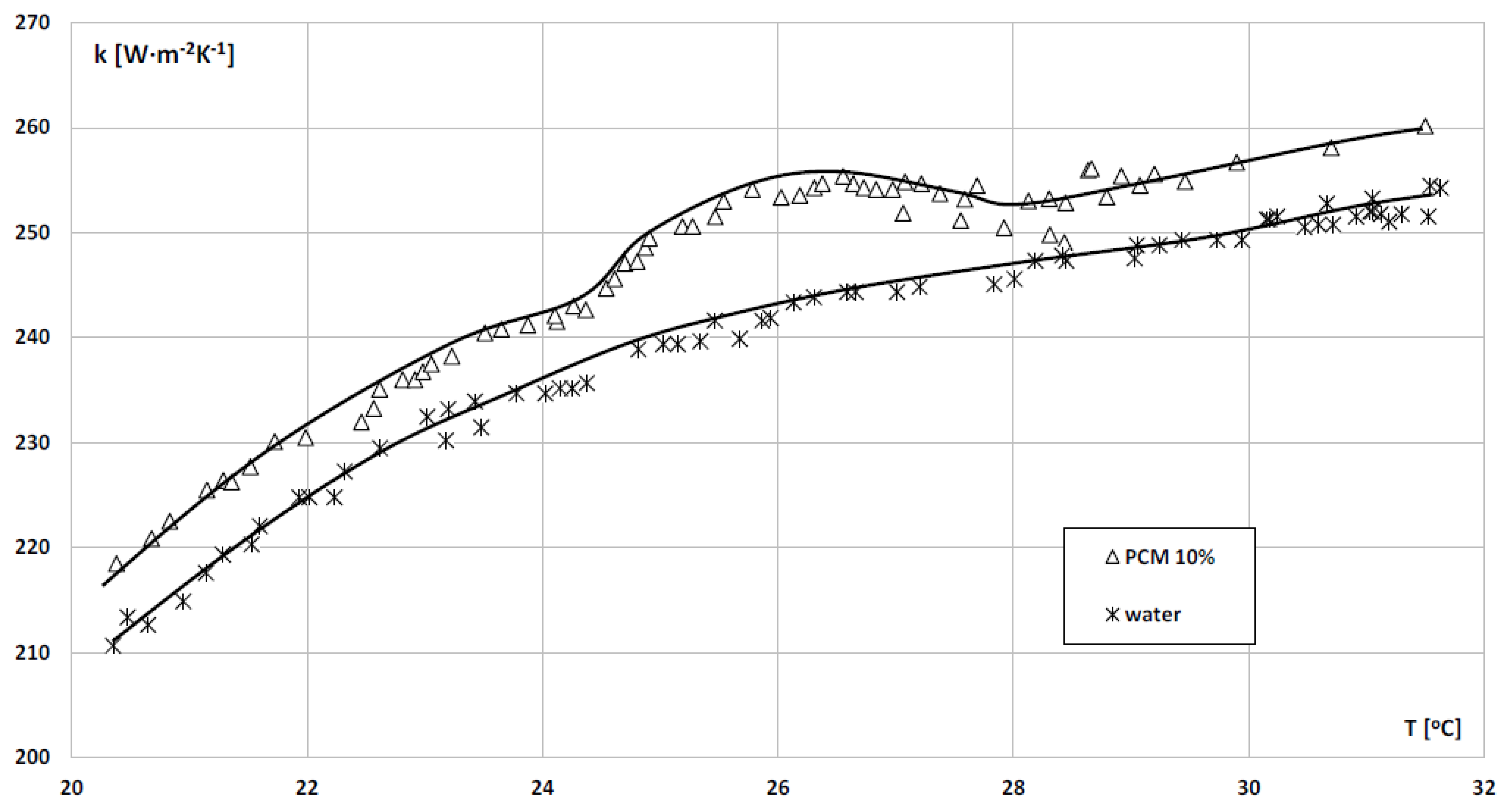
  • Development of the experimental characteristics of the shell and tube exchanger in the form of the dependence of the heat output of the exchanger, the heat transfer coefficient αexp, and the overall heat transfer coefficient k on the temperature of the coolant at the inlet to the heat exchanger.
  • The experiment showed that in the temperature range at which the phase change of the MPCM material occurred (25.5–30 °C), there was a clear increase in the intensification of heat exchange and an increase in the heat output of the exchanger.
  • The use of phase change materials as carrier fluid (HTF) in the shell and tube heat exchanger increased the value of the overall heat transfer coefficient k by up to 9% compared to the use of the reference fluid (water).
  • The increase in the coolant heat transfer rate averaged 13%, and the peak increase in αexp was over 24%.
  • The average value of the overall heat transfer coefficient k increased by 5%, and the highest increases in the value of k were observed at Tin = 27 °C of 9% in relation to the reference liquid.

Author Contributions

Conceptualization, M.K. and T.B.; methodology, M.K. and K.D.; software, M.K. and K.D.; validation, M.K., M.R., K.D. and T.B.; formal analysis, K.D. and M.K.; investigation M.K.; resources, T.B.; data curation, M.K. and K.D.; writing—original draft preparation, M.K. and K.D.; writing—review and editing, M.K. and K.D.; visualization, M.K., M.R., K.D. and T.B.; supervision, K.D., M.K. and T.B. All authors have read and agreed to the published version of the manuscript.

Funding

The research was funded by Polish National Science Center, grant number: 2021/05/X/ST8/00023.

Institutional Review Board Statement

Not applicable.

Informed Consent Statement

Not applicable.

Data Availability Statement

Not applicable.

Conflicts of Interest

The authors declare no conflict of interest.

Nomenclature

Aarea (m2)
ddiameter (m)
Gmass flux density (kg·m−2·s−1)
dimensionless quantity
henthalpy (J·k−1)
Llength (m)
mass flow rate (kg·h−1)
NuNusselt number
qheat flux density (W·m−2)
Qheat flux (W)
rheat of condensation/evaporation (J·k−1)
ReReynolds number
ttemperature (°C)
Ttemperature (K)
Index
ccondensation, coolant
expexperiment
eexternal
ffluid
hhydraulic
iinternal
lliquid
ththeoretical
ttotal
tptwo-phase
vvapor
wwall, water
free stream
Greek symbols
αheat transfer coefficient (W·m−2·K−1)
Δdifference
λthermal conductivity (W·m−1·K−1)
νkinematic viscosity (m−2 s−1)
Acronyms
HEheat exchanger
HTCheat transfer coefficient
HTFheat transfer fluid
MPCMmicroencapsulated phase change material

References

  1. Li, Y.; Zhu, N.; Lv, S. Experimental study of phase change materials coupled solar thermal energy for building heating in winter. IOP Conf. Ser. Earth Environ. Sci. 2019, 237, 042010. [Google Scholar] [CrossRef]
  2. Moghaddam, M.A.E.; Ganji, D.D. A comprehensive evaluation of the vertical triplex-tube heat exchanger with PCM, concentrating on flow direction, nanoparticles and multiple PCM implementation. Therm. Sci. Eng. Prog. 2021, 26, 101124. [Google Scholar] [CrossRef]
  3. Mozafari, M.; Lee, A.; Cheng, S. A novel dual-PCM configuration to improve simultaneous energy storage and recovery in triplex-tube heat exchanger. Int. J. Heat Mass Transf. 2022, 186, 122420. [Google Scholar] [CrossRef]
  4. Al-Abidi, A.A.; Mat, S.; Sopian, K.; Sulaiman, M.Y.; Mohammad, A.T. Experimental study of melting and solidification of PCM in a triplex tube heat exchanger with fins. Energy Build. 2014, 68, 33–41. [Google Scholar] [CrossRef]
  5. NematpourKeshteli, A.; Iasiello, M.; Langella, G.; Bianco, N. Enhancing PCMs thermal conductivity: A comparison among porous metal foams, nanoparticles and finned surfaces in triplex tube heat exchangers. Appl. Therm. Eng. 2022, 212, 118623. [Google Scholar] [CrossRef]
  6. Talebizadehsardari, P.; Mahdi, J.M.; Mohammed, H.I.; Moghimi, M.; Eisapour, A.H.; Ghalambaz, M. Consecutive charging and discharging of a PCM-based plate heat exchanger with zigzag configuration. Appl. Therm. Eng. 2021, 193, 116970. [Google Scholar] [CrossRef]
  7. Garg, H.; Pandey, B.; Saha, S.K.; Singh, S.; Banerjee, R. Design and analysis of PCM based radiant heat exchanger for thermal management of buildings. Energy Build. 2018, 169, 84–96. [Google Scholar] [CrossRef]
  8. Kabir, M.; Gemeda, T.; Preller, E.; Xu, J. Design and Development of a PCM-Based Two-Phase Heat Exchanger Manufactured Additively for Spacecraft Thermal Management Systems. Int. J. Heat Mass Transf. 2021, 180, 121782. [Google Scholar] [CrossRef]
  9. Dardir, M.; El Mankibi, M.; Haghighat, F.; Klimes, L. Development of PCM-to-air heat exchanger for integration in building envelope–modeling and validation. Sol. Energy 2019, 190, 367–385. [Google Scholar] [CrossRef]
  10. Santos, T.; Kolokotroni, M.; Hopper, N.; Yearley, K. Experimental study on the performance of a new encapsulation panel for PCM’s to be used in the PCM-Air heat exchanger. Energy Procedia 2019, 161, 352–359. [Google Scholar] [CrossRef]
  11. Pássaro, J.; Rebola, A.; Coelho, L.; Conde, J.; Evangelakis, G.; Prouskas, C.; Papageorgiou, D.; Zisopoulou, A.; Lagaris, I. Effect of fins and nanoparticles in the discharge performance of PCM thermal storage system with a multi pass finned tube heat exchange. Appl. Therm. Eng. 2022, 212, 118569. [Google Scholar] [CrossRef]
  12. Liu, L.; Li, J.; Niu, J.; Wu, J.-Y. Evaluation of the energy storage performance of PCM nano-emulsion in a small tubular heat exchanger. Case Stud. Therm. Eng. 2021, 26, 101156. [Google Scholar] [CrossRef]
  13. Gholamibozanjani, G.; Farid, M. Experimental and mathematical modeling of an air-PCM heat exchanger operating under static and dynamic loads. Energy Build. 2019, 202, 109354. [Google Scholar] [CrossRef]
  14. Promoppatum, P.; Yao, S.-C.; Hultz, T.; Agee, D. Experimental and numerical investigation of the cross-flow PCM heat exchanger for the energy saving of building HVAC. Energy Build. 2017, 138, 468–478. [Google Scholar] [CrossRef]
  15. Maccarini, A.; Hultmark, G.; Bergsøe, N.C.; Afshari, A. Free cooling potential of a PCM-based heat exchanger coupled with a novel HVAC system for simultaneous heating and cooling of buildings. Sustain. Cities Soc. 2018, 42, 384–395. [Google Scholar] [CrossRef]
  16. Yang, D.; Shi, R.; Wei, H.; Du, J.; Wang, J. Investigation of the performance of a cylindrical PCM-to-air heat exchanger (PAHE) for free ventilation cooling in fluctuating ambient environments. Sustain. Cities Soc. 2019, 51, 101764. [Google Scholar] [CrossRef]
  17. Zhu, Y.; Xiao, J.; Chen, T.; Chen, A.; Zhou, S.; Liu, Z.; Xia, Z. Experimental and numerical investigation on composite phase change material (PCM) based heat exchanger for breathing air cooling. Appl. Therm. Eng. 2019, 155, 631–636. [Google Scholar] [CrossRef]
  18. Herbinger, F.; Groulx, D. Experimental comparative analysis of finned-tube PCM-heat exchangers’ performance. Appl. Therm. Eng. 2022, 211, 118532. [Google Scholar] [CrossRef]
  19. Pakalka, S.; Valančius, K.; Streckienė, G. Experimental comparison of the operation of PCM-based copper heat exchangers with different configurations. Appl. Therm. Eng. 2020, 172, 115138. [Google Scholar] [CrossRef]
  20. Wu, J.; Feng, Y.; Liu, C.; Li, H. Heat transfer characteristics of an expanded graphite/paraffin PCM-heat exchanger used in an instantaneous heat pump water heater. Appl. Therm. Eng. 2018, 142, 644–655. [Google Scholar] [CrossRef]
  21. Dardir, M.; Panchabikesan, K.; Haghighat, F.; El Mankibi, M.; Yuan, Y. Opportunities and challenges of PCM-to-air heat exchangers (PAHXs) for building free cooling applications—A comprehensive review. J. Energy Storage 2019, 22, 157–175. [Google Scholar] [CrossRef]
  22. Kalapala, L.; Devanuri, J.K. Influence of operational and design parameters on the performance of a PCM based heat exchanger for thermal energy storage—A review. J. Energy Storage 2018, 20, 497–519. [Google Scholar] [CrossRef]
  23. Sadeghi, H.M.; Babayan, M.; Chamkha, A. Investigation of using multi-layer PCMs in the tubular heat exchanger with periodic heat transfer boundary condition. Int. J. Heat Mass Transf. 2019, 147, 118970. [Google Scholar] [CrossRef]
  24. Elsanusi, O.S.; Nsofor, E.C. Melting of multiple PCMs with different arrangements inside a heat exchanger for energy storage. Appl. Therm. Eng. 2020, 185, 116046. [Google Scholar] [CrossRef]
  25. Gorzin, M.; Hosseini, M.J.; Rahimi, M.; Bahrampoury, R. Nano-enhancement of phase change material in a shell and multi-PCM-tube heat exchanger. J. Energy Storage 2019, 22, 88–97. [Google Scholar] [CrossRef]
  26. Bakhshipour, S.; Valipour, M.S.; Pahamli, Y. Analyse paramétrique de réfrigérateurs domestiques utilisant un échangeur de chaleur à matériau à changement de phase. Int. J. Refrig. 2017, 83, 1–13. [Google Scholar] [CrossRef]
  27. Al-Mudhafar, A.H.N.; Nowakowski, A.F.; Nicolleau, F.C. Performance enhancement of PCM latent heat thermal energy storage system utilizing a modified webbed tube heat exchanger. Energy Rep. 2020, 6, 76–85. [Google Scholar] [CrossRef]
  28. Fu, Z.; Liang, X.; Li, Y.; Li, L.; Zhu, Q. Performance improvement of a PVT system using a multilayer structural heat exchanger with PCMs. Renew. Energy 2020, 169, 308–317. [Google Scholar] [CrossRef]
  29. Morovat, N.; Athienitis, A.K.; Candanedo, J.A.; Dermardiros, V. Simulation and performance analysis of an active PCM-heat exchanger intended for building operation optimization. Energy Build. 2019, 199, 47–61. [Google Scholar] [CrossRef]
  30. Abidi, A.; Rawa, M.; Khetib, Y.; Sindi, H.F.A.; Sharifpur, M.; Cheraghian, G. Simulation of melting and solidification of graphene nanoparticles-PCM inside a dual tube heat exchanger with extended surface. J. Energy Storage 2021, 44, 103265. [Google Scholar] [CrossRef]
  31. Prieto, M.; González, B.; Granado, E. Thermal performance of a heating system working with a PCM plate heat exchanger and comparison with a water tank. Energy Build. 2016, 122, 89–97. [Google Scholar] [CrossRef]
  32. Zeng, R.; Wang, X.; Chen, B.; Zhang, Y.; Niu, J.; Wang, X.; Di, H. Heat transfer characteristics of microencapsulated phase change material slurry in laminar flow under constant heat flux. Appl. Energy 2009, 86, 2661–2670. [Google Scholar] [CrossRef]
  33. Yang, L.; Liu, S.; Zheng, H. A comprehensive review of hydrodynamic mechanisms and heat transfer characteristics for microencapsulated phase change slurry (MPCS) in circular tube. Renew. Sustain. Energy Rev. 2019, 114, 109312. [Google Scholar] [CrossRef]
  34. Ran, F.; Chen, Y.; Cong, R.; Fang, G. Flow and heat transfer characteristics of microencapsulated phase change slurry in thermal energy systems: A review. Renew. Sustain. Energy Rev. 2020, 134, 110101. [Google Scholar] [CrossRef]
  35. Liu, C.; Ma, Z.; Wang, J.; Li, Y.; Rao, Z. Experimental research on flow and heat transfer characteristics of latent functional thermal fluid with microencapsulated phase change materials. Int. J. Heat Mass Transf. 2017, 115, 737–742. [Google Scholar] [CrossRef]
  36. Kruzel, M.; Bohdal, T.; Dutkowski, K. External Condensation of HFE 7000 and HFE 7100 Refrigerants in Shell and Tube Heat Exchangers. Materials 2021, 14, 6825. [Google Scholar] [CrossRef]
  37. Microtek Labs. MICRONAL® DS 5039 X Technical Data. Available online: https://www.google.com.hk/url?sa=t&rct=j&q=&esrc=s&source=web&cd=&ved=2ahUKEwikzKjyqvr4AhW2SGwGHdznCEgQFnoECAMQAQ&url=https%3A%2F%2Fcdn2.hubspot.net%2Fhubfs%2F4153344%2FMicrotek%2520Laboratories%2520December2017%2FPDF%2FMPDS3300-0045%2520Rev%25201.pdf%3Ft%3D1516975227818&usg=AOvVaw1tfZCEyCYjirP89yCvjgVL (accessed on 13 July 2022).
  38. Dutkowski, K.; Kruzel, M.; Zajączkowski, B.; Białko, B. The experimental investigation of mPCM slurries density at phase change temperature. Int. J. Heat Mass Transf. 2020, 159, 120083. [Google Scholar] [CrossRef]
  39. Dutkowski, K.; Kruzel, M.; Zajączkowski, B. Determining the Heat of Fusion and Specific Heat of Microencapsulated Phase Change Material Slurry by Thermal Delay Method. Energies 2020, 14, 179. [Google Scholar] [CrossRef]
  40. Dutkowski, K.; Kruzel, M. Microencapsulated PCM slurries’ dynamic viscosity experimental investigation and temperature-dependent prediction model. Int. J. Heat Mass Transf. 2019, 145, 118741. [Google Scholar] [CrossRef]
  41. Dutkowski, K.; Kruzel, M. Experimental Investigation of the Apparent Thermal Conductivity of Microencapsulated Phase-Change-Material Slurry at the Phase-Transition Temperature. Materials 2021, 14, 4124. [Google Scholar] [CrossRef]
  42. Dutkowski, K.; Kruzel, M.; Bohdal, T. Experimental Studies of the Influence of Microencapsulated Phase Change Material on Thermal Parameters of a Flat Liquid Solar Collector. Energies 2021, 14, 5135. [Google Scholar] [CrossRef]
Figure 1. General view of the shell and tube heat exchanger.
Energies 15 05142 g001
Figure 2. Schematic diagram of the experimental facility: 1—shell and tube heat exchanger; 2—HFE 7000 line Coriolis type mass flow meter; 3—MPCM slurry leveling vessel; 4—spiral coil heat exchanger; 5—MPCM slurry line Coriolis type mass flow meter; 6—pressure sensors; 7—circulation pump; 8—chiller; 9—recording device; 10—HFE 7000 vessel with heater; 11—autotransformer.
Energies 15 05142 g002
Figure 3. The dependency of the heat of fusion on the coolant inlet temperature for pure water and an aqueous solution of 10% wt. MPCM in water.
Energies 15 05142 g003
Figure 4. The heat flux versus the inlet temperature of the cooling liquid for pure water and an aqueous solution of water and 10% wt. MPCM.
Energies 15 05142 g004
Figure 5. The dependence of the heat transfer coefficient αexp on the coolant temperature at the inlet of the heat exchanger’s cooling section.
Energies 15 05142 g005
Figure 6. The dependence of the overall heat transfer coefficient k on the coolant temperature at the inlet of the heat exchanger’s cooling section.
Energies 15 05142 g006
Table 1. The measuring equipment uncertainty.
Measured ValueDeviceMeasuring RangeMax. Uncertainty
(of the Measured Value)
Mass flow rateMass flow meters0–450 kg·h−1±0.15%
PressurePiezoresistive sensor0–2500 kPa±0.05%
Differential sensor0–50 kPa±0.075%
TemperatureThermocouple TP-201K-1B-100−40–+475 °C±0.2 K
Publisher’s Note: MDPI stays neutral with regard to jurisdictional claims in published maps and institutional affiliations.

