Article

Modelling and Design of a Coils Structure for 100 kW Three-Phase Inductive Power Transfer System

Department of Energy, Politecnico di Torino, Corso Duca degli Abruzzi 24, 10129 Torino, Italy
*
Author to whom correspondence should be addressed.
Energies 2022, 15(14), 5079; https://doi.org/10.3390/en15145079
Submission received: 11 June 2022 / Revised: 4 July 2022 / Accepted: 6 July 2022 / Published: 12 July 2022
(This article belongs to the Special Issue Electric Vehicle Charging Networks)

Abstract

:
This paper presents the modeling, the design and verification of a three-phase coil structure for high-power Wireless-Power-Transfer (WPT) in automotive applications. The system, a Three-Polar-Pad (TPP), with complex mechanical geometry, is analytically modeled with an equivalent simplified structure. Thanks to this simplification, a numerical design is performed to minimize cross-coupling effects among different phases of the same side (receiver or transmitter) maximizing the linkage flux receiver-to-transmitter and then the power transferred. The analytical model is then verified in a Finite-Element-Analysis (FEA) environment. A final design, comprehensive of the shielding, is proposed matching the preliminary design constraints. Hence, the preliminary model is verified by testing a prototype using a three-phase Silicon Carbide (SiC) inverter at the transmitter side. The capability of the system is demonstrated by transferring 100 kW with more than 94% DC-to-DC efficiency over a 50 mm air gap in perfectly aligned conditions.

1. Introduction

Nowadays, the reduction of greenhouse gases is a key aspect. In fact, an energy transition is occurring, even though more restrictive laws on emission, towards clean energy sources. This process also involves the automotive sector, where an electric revolution occurs. New challenges are emerging, including the process of Electric Vehicle (EV) charging [1,2]. Next to a more traditional cable recharge [3,4] , it is possible to adopt wireless solutions [5,6], which allow greater accessibility, are user-friendly, and guarantee greater safety as there is no physical contact between the source and the vehicle during the recharging procedure. In the literature, it is possible to distinguish two possible wireless charging solutions: the static [7] and the dynamic one [8,9]. In the latter, a possible architecture is the singular coil rack [10,11] with a single transmitting coil on the charging path and the receiving coil on the moving vehicle that captures the horizontal flux. Static recharging instead, compared to a dynamic one, allows a greater coupling coefficient as the linkage flow is the vertical one, thus obtaining greater control of the charging process [12].
In literature, there are many studies on single-phase systems with different coil geometries, for instance, circular, rectangular [13] or double-D coil (DD) geometry [14]. Many analytical models for coil design have been presented and proposed for square geometry [15] or for circular one [16]. However, when it is required to increase the power of the charging system, so to minimize the charging time, it is possible to adopt a multiphase structure [17,18]. This solution allows, as demonstrated in [19], to reduce the emitted field compared to an equivalent single-phase structure. A multiphase solution also ensures lower stress of the filter components at the output of the system [20]. Considering three-phase structures, it is possible to find in the literature architecture where the coil system is a three-phase coupler pad using single-phase windings [21,22]. An alternative structure is one where the coils of the single phases are overlapped by an angle such that ideally, the phases are decoupled from each other, the three polar pad (TTP), as already proved in [23]. However, a detailed numerical analysis to obtain this angle was not discussed.
This paper provides a detailed analysis and modeling of the TTP three-phase system, where the phases of transmitters (Tx) and receivers (Rx) are symmetrical and overlapped, as in the Figure 1. This coil configuration through phases overlapping allows to minimize the mutual magnetic coupling between adjacent phases. In particular, this paper proposes a systematic numerical pattern for the coil structure design of a three-phase WPT application. A numerical evaluation of the mutual inductance is proposed here, using a circular equivalent geometry represented in Figure 2 to obtain simplified formulations. Thus a novel first sizing procedure of the electromagnetic structure in terms of desired mutual inductance value and, at the same time, the definition of the optimal overlapping angle between the coils to minimize the coupling effects among different phases at both the Rx and Tx is presented. As a validation of the simplification used for the numerical analysis, the results obtained are compared with a finite element analysis (FEA).
The paper follows the structure presented next. Section 2 presents the WPT final system under analysis and the related design constraints. In Section 3, a detailed numerical study is provided, applied to a simplified equivalent structure, reaching a preliminary coils’ geometrical dimensions also in terms of the number of turns and overlapping angle. Section 4 compares the previous mathematical model results with a FEA design of the final WPT system to validate the proposed analytical method. In Section 5, as a final step of validation, measurements are given of a prototype realized following the design proposed in the previous sections. In the last section, the conclusions of the presented analysis are highlighted, giving a perspective of the research and of the future activities.

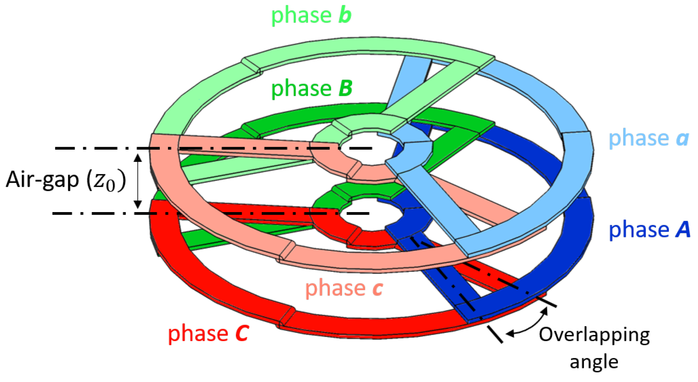
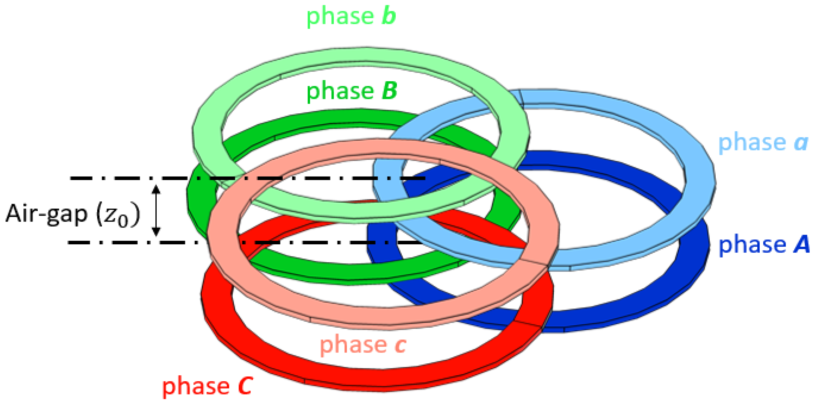
2. System Modelling & Problem Definition

The core structure of the WPT system, the electromagnetic structure that is proposed to be sized and simulated, is shown in Figure 1. This is a three-phase system where the coils of phases A, B, and C appertaining to the transmitter coil are highlighted; furthermore, the coils of phases a, b, and c representing the receiver coil are distinguished. The on-ground transmitter coil, will be powered by a three-phase SiC inverter, while the on-board receiver coil will be connected to a three-phase diode rectifier, generating in this way a unidirectional charging structure.
The starting point for the following analysis is a set of parameters, given data for the problem. These guidelines, shown in the Table 1, represent the mechanical and electrical constraints defined by the EV’s manufacturing partner.

3. Numerical Pre-Design

Assume now that from the energetic point of view the three-phase system acts as three independent single phase systems. It is possible to calculate the mutual inductance for every single coil [24] starting from a rated power equal to P 2 a c = 2 P D C o u t 3 3 [25,26] as in (1), where ω 0 = 2 π f 0 .
M = 8 π 2 V D C i n V D C o u t ω 0 P 2 a c = 8 π 2 V D C i n V D C o u t ω 0 P D C o u t 3 3 2
Substituting the parameters of the Table 1 in (1), it is possible to obtain the target mutual inductance, M o b j = 8.69 μ H. This value represents the desired mutual inductance of each individual Tx-Rx couple coil to transmit the required power. Therefore, it is the target value to be reached during the coil sizing process.
This result is obtained considering a series capacitive compensation; anyway, for other compensation topologies, the evaluation can be done in a similar way [27,28,29,30].

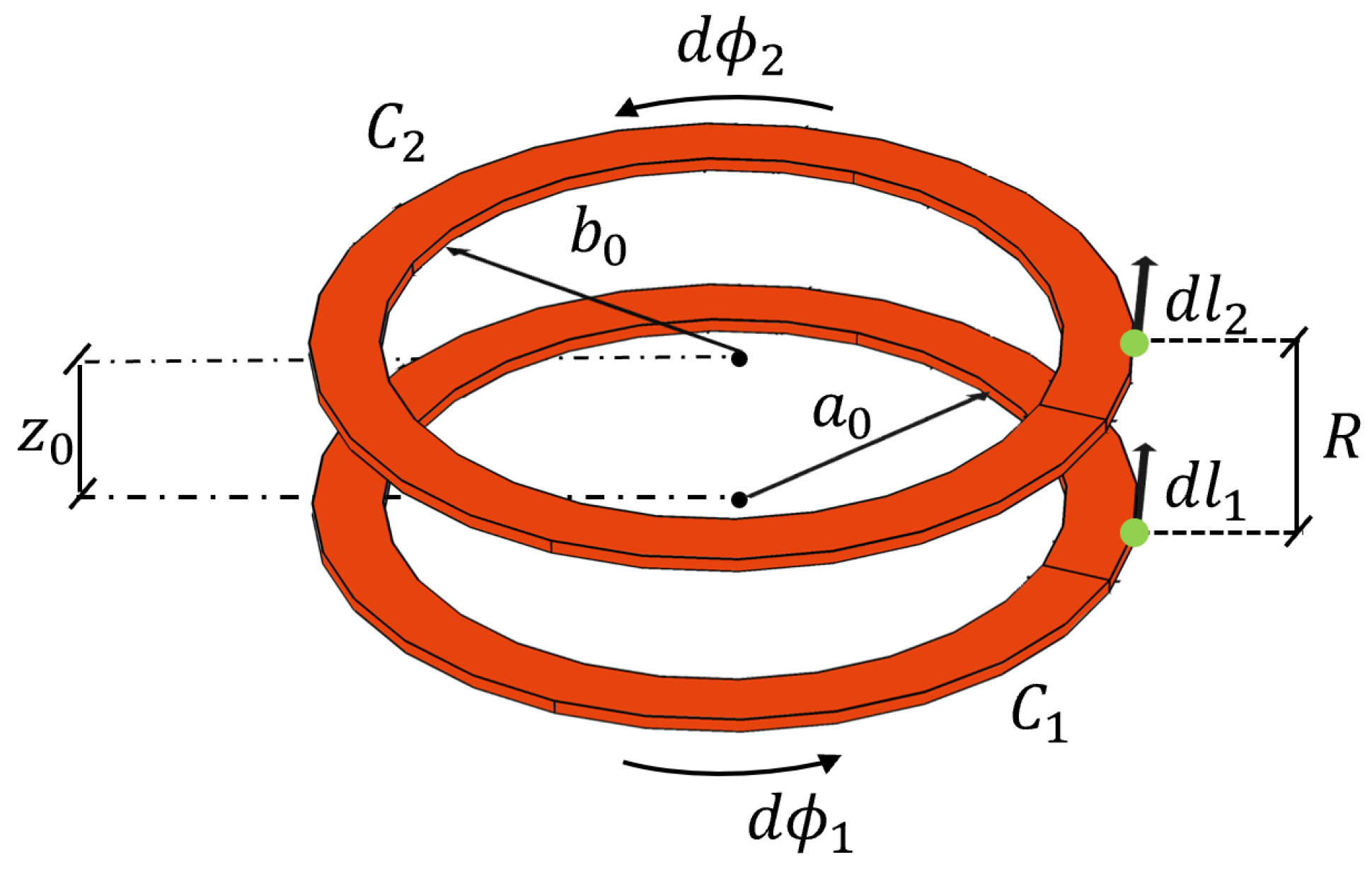
3.1. Mutual Inductance: Calculation

The first step in the numerical analysis is to obtain the analytical formulation of the mutual inductance between coils. Hence, the mutual inductance between spiral coils can be generically implemented as the ratio between the linked flux in one coil by the current in another one using Neumann’s equation [31,32,33]. Obtaining such a formulation on a complex geometry as presented in Figure 1 can be uselessly difficult. So, to obtain simpler equations, a circular geometry as in Figure 2 was adopted.
To adopt this approximation the inner area of a single coil is equal between Figure 1 and Figure 2, to guarantee the same linkage flux for the circular geometry compared with the final one. Thus, the results obtained for the simplified model can be directly passed to the final one of Figure 1, obtaining in this way pre-design effective procedure.
The mutual inductance between two coils, as an example, with reference to the model of Figure 3, can be then determined as in (2).
M 21 = μ 0 4 π C 1 C 2 d l 1 · d l 2 R
where d l 1 and d l 2 are the tangential elements at the same point on C 1 and C 2 , the circumferences that describe the two coils in analysis, while R represents the distance between these two points.
Equation (2) can lead to a complex estimation of the mutual inductance between the two coils. Thus, as a further simplified step of the evaluation, the integration terms are converted from rectangular coordinates to cylindrical ones.

3.2. Concentric Coils Mutual Inductance

Assuming that the two coils under study are concentric, the integration passes from a close loop form to a finite one over the limits [ 0 , 2 π ] . Considering the generic distance z 0 of the two coils along the axis of the centers and assuming negligible the cross-section and the number of the turns it is possible to write the distance R in cylindrical coordinates as in (3).
R = z 0 2 + [ a 0 c o s ϕ 1 b 0 c o s ϕ 2 ] 2 + [ a 0 s i n ϕ 1 b 0 s i n ϕ 2 ] 2 = z 0 2 + a 0 2 + b 0 2 2 a 0 b 0 c o s ( ϕ 1 ϕ 2 )
Taking into account the previous considerations, the mutual inductance can be written as in (4).
M 12 = μ 0 4 π 0 2 π 0 2 π a 0 b 0 ( c o s ( ϕ 1 ϕ 2 ) s i n ( ϕ 1 ϕ 2 ) ) d ϕ 1 d ϕ 2 z 0 2 + a 0 2 + b 0 2 2 a 0 b 0 c o s ( ϕ 1 ϕ 2 )
To analyze the mutual inductance between two multi-turn coils, Equation (4) needs to be modified. In particular,with reference to Figure 3, assuming a o , b o the inner radius of the circular coils under study, d s 1 , d s 2 the cross-section of a single turn of the coils and N s 1 , N s 2 the number of turn for each coil, the generic radius of the coil identified by a single turn results in (5) referred to Figure 3.
a i = a o + ( i 1 ) d s 1 b j = b o + ( j 1 ) d s 2
where i and j identify the number of turns examined in the coils under study.
Hence the total mutual inductance, as a contribution of all the turns of both coils, can be rewritten as in (6)
M t o t = i = 1 N s 1 j = 1 N s 2 M 12 i j
where the contribution of a single generic turn of each coil referred to Figure 3 is reported in (7).
M 12 i j = μ 0 4 π 0 2 π 0 2 π a i b j ( c o s ( ϕ 1 ϕ 2 ) s i n ( ϕ 1 ϕ 2 ) ) d ϕ 1 d ϕ 2 z 0 2 + a i 2 + b j 2 2 a i b j c o s ( ϕ 1 ϕ 2 )

3.3. Non-Concentric Coils Mutual Inductance

In case of two non-concentric coil, some considerations as to be taken. In particular the distance R between the two infinitesimal elements d l 1 and d l 2 on C 1 and C 2 needs to be rearranged as in (8).
R = z 0 2 + [ m c o s α + a c o s ϕ 1 b c o s ϕ 2 ] 2 + [ m s i n α + a s i n ϕ 1 b s i n ϕ 2 ] 2
where the term m represents the module of the distance of the centers of the two non-concentric coils C 1 and C 2 , while α is the angle from the x-axis and the location of the centers. Thus, the mutual inductance can now be recalculated in a general formulation as in (9).
M 12 i j = μ 0 4 π 0 2 π 0 2 π a i b j ( c o s ( ϕ 1 ϕ 2 ) s i n ( ϕ 1 ϕ 2 ) ) d ϕ 1 d ϕ 2 z 0 2 + [ m c o s α + a i c o s ϕ 1 b j c o s ϕ 2 ] 2 + [ m s i n α + a i s i n ϕ 1 b j s i n ϕ 2 ] 2

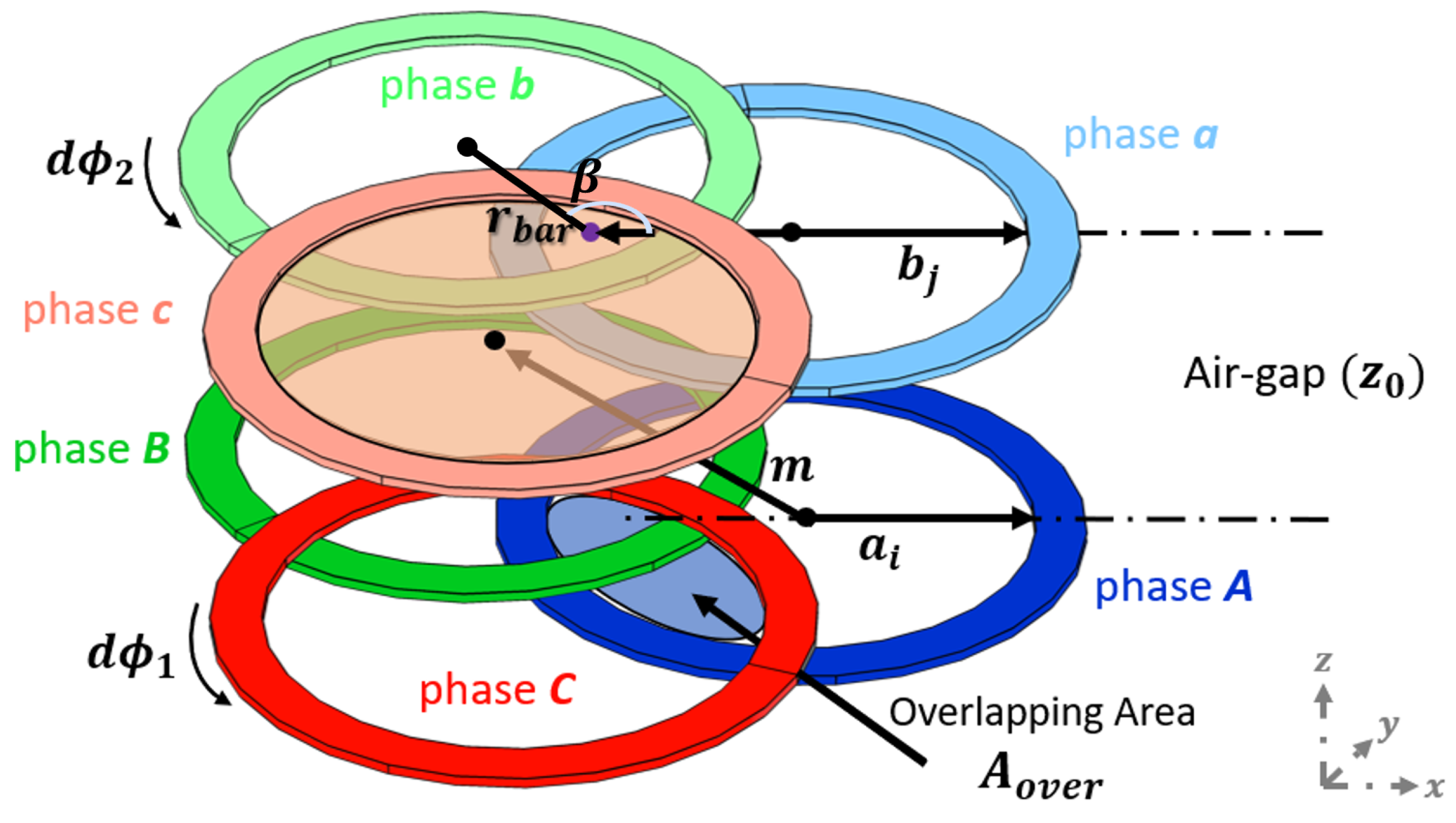
3.4. Three-Phase Structure Non-Concentric Coil Mutual Inductance

Considering now a three-phase structure as in Figure 4, and examining the coil of the Rx as an example, it is possible to identify r b a r representing the distance of the center of a single coil and the absolute center of the whole 3-Ph structure.
The angle that subtends the centers of two adjacent coils in the same plane and the absolute center is referred to as β . It is assumed in the discussion that given the structure under study both at Rx and Tx, β is equal to 120 mechanical degrees. It is, therefore, possible through (10) to calculate the distance m between two centers.
m = 2 r b a r s i n β 2
A detailed analysis has to be done regarding the identification of the term r b a r which represents the distance of the center of a single-coil under study and the absolute center of the whole 3-Ph structure.
To determine the previous quantities, it has to be taken then into account the structure composed of C 1 and C 2 . It is then possible to highlight the overlapping area A o v e r of the two coils, which is the active surface responsible for concatenating the magnetic field. This area can be expressed as a function of the distance of the centers m and the angle α as in (11).
A o v e r = a 0 2 ( α 1 2 sin α 1 cos α 1 ) + b 0 2 ( α 2 2 sin α 2 cos α 2 )
This formulation allows analysis with coils of different sizes, however, considering the case under study where coils of equal size are considered, it is possible to perform a simplification and obtain (12).
A o v e r = 2 a 0 2 ( α 2 s i n α c o s α )
From Equation (12), the quantity α can be calculated, assuming A o v e r known.
Once the angle α is determined, it is also possible to calculate the term r b a r . In fact, the distance between the centers m can be determined, in addition to (10), also as a function of the radius of the single coil and the angle which subtends the overlapping sector.
m = 2 a 0 c o s ( α )
By substituting (13) in (10) it is possible to obtain (14).
r b a r = a 0 c o s ( α ) s i n β 2
In this way the solution for the distance of the centers m becomes known as a function of the overlapping area A o v e r .
As a consequence (13) becomes solvable and the angles ϕ 1 , ϕ 2 allow to express the value of the mutual inductance between the two adjacent coils function of the overlapping area A o v e r .
Considering now a structure made by three circular sectors with 120 mechanical opening angle each, it is possible to make some adjustments in the above analysis. In particular, assuming a generic opening angle added to the already mentioned 120 , it is clear that two adjacent coils have an overlapping surface function of the above angle as reported in (15).
A o v e r = A t o t s e c α o v e r A 120 s e c 2 = π r e x t i n t 2 r i n t i n t 2 α o v e r 2 π
where:
  • A t o t s e c α o v e r is the total surface of the coil considering the overlapping and then function of the total opening angle of: 120 + 2 α o v e r .
  • A 120 s e c is the surface of the coil not considering the overlapping, with an opening angle of 120 .
  • r e x t i n t is the outer radius of the sector-coil net of the turns cross section area.
  • r i n t i n t is the inner radius of the sector-coil net of the turns cross section area.
  • α o v e r is the overlapping angle of two adjacent coils.
With reference to the above terms, all the geometric parameters are known except the overlapping angle α o v e r . This angle could be considered a variable and the mutual inductance calculated as a function of α o v e r for the 3-Ph structure described above. However, to calculate the mutual inductance, it is necessary to consider that the overlapping angle affects the radius a o of the single coil. Indeed the inner area of a multi-turn structure is modified by the addition of the overlapping area. As a consequence the final inner radius of a single coil a o α o v e r is equal to (16).
a o α o v e r = ( π a 2 ) + A o v e r π
Thus, a more generic relationship for the multi-turn-based mutual inductance of two non concentric overlapped coils can be evaluated as in (17) considering the influence of the overlapping area
M 12 i j α o v e r = μ 0 4 π 0 2 π 0 2 π a i α o v e r b j α o v e r · ( c o s ( ϕ 1 ϕ 2 ) s i n ( ϕ 1 ϕ 2 ) ) d ϕ 1 d ϕ 2 z 0 2 + x 2 ( α o v e r ) + y 2 ( α o v e r )
where:
  • x ( α o v e r ) = m α o v e r c o s α α o v e r + a i α o v e r c o s ϕ 1 b j α o v e r c o s ϕ 2
  • y ( α o v e r ) = m α o v e r s i n α α o v e r + a i α o v e r s i n ϕ 1 b j α o v e r s i n ϕ 2
Analyzing more in detail the Equation (17) it is possible to notice that also the radii of the equivalent circular structure of the coils are a function of the overlapping angle α o v e r . This is because the comparison between the 3-Ph structure and the equivalent circular coils has been performed, maintaining the active surface that concatenated the magnetic field as a constant.
Thus, by substituting (17) in (6), it is possible to calculate the mutual inductance as a function of the number of turns, their mutual position, and the overlapping angle. As α o v e r and the number of turns change, it is possible to obtain the trend of the mutual inductance as a function of these parameters. During the study, the number of turns is considered the same for all coils (Tx and Rx) that compose the structure.

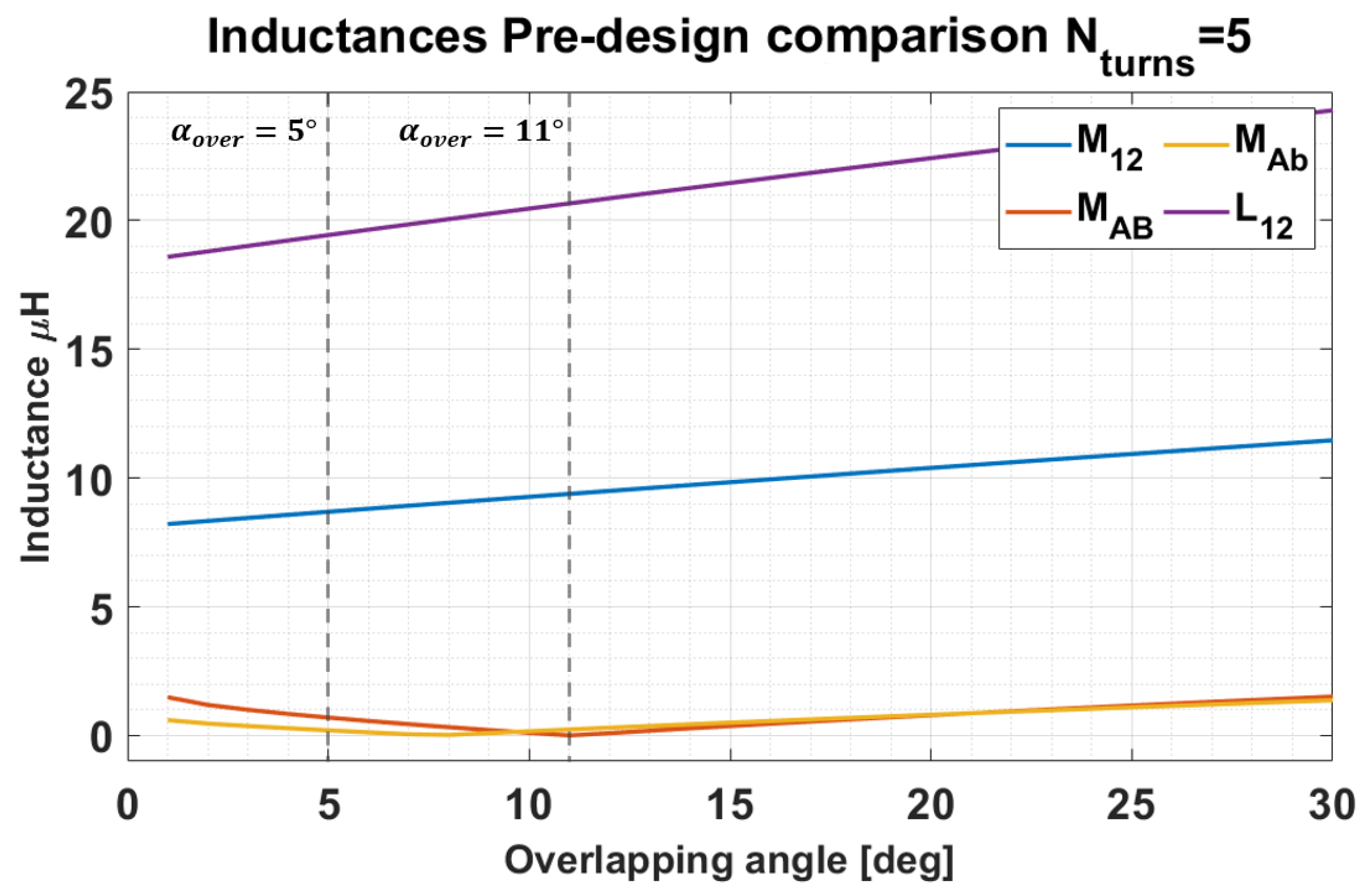
3.5. Objective and Pre-Design Comparison

As defined in Section 2, the target mutual inductance value is equal to M o b j = 8.69 μ H. Subtracting this value with the mutual inductance M t o t calculated with (6) and (17) as the number of turns and the overlapping angle changes, it is possible to find an optimum, the point where this difference is minimal, represented in Figure 5a by the red dot. In this way, it is possible to obtain the needed number of turns and the overlapping angle to transfer the required power.
In Figure 5a, the iso-lines represents a variation of 1 μ H in terms of mutual inductance gradient. The couplings between turns of different phases are not desired, as electromagnetic decoupling between phases is desirable. So ideally, the mutual inductance values for cross-coupling for coplanar and non-coplanar coils, e.g., M A B and M A b should tend to 0. Figure 5b,c shows the difference between the desired value ( 0 μ H) and the value calculated by the analytical model for cross-coupling for non-coplanar coils in the first one and coplanar coils in the second one. Highlighted by a red dot is the point of optimum for these values, while in yellow, the values considering the turns and overlapping angle that allow transferring the required power. The iso-lines in Figure 5b,c represents a variation of 500 nH in terms of mutual inductance gradient. Analogous consideration is done for the self-inductance, calculated with the numerical model, represented in Figure 5d. Moreover, in this graph, the iso-lines define a variation of 500 nH in terms of mutual inductance gradient.
If now an error greater than e m u t u a l 5 % is admitted for the direct mutual inductance, a variation in the variables of the system can be implemented to reach a better common design point.
Table 2 shows that the error of direct mutual inductance increases to e m u t u a l 7 % . Despite this, increasing the overlapping angle results in a large reduction of cross-coupling effects. The greater of these inductance, the no coplanar cross-coupling one, is indeed very small compared with direct mutual inductance, just the 2 % . Hence, the contribution to the field can be considered negligible compared to the direct field transmission.
In Figure 6, the trend for every inductance referenced in Table 2 are depicted to have a better perspective of the decisional design process.

3.6. Resonance Topology

A little dissertation is given here regarding the compensation network to provide the needed information to understand better the experimental validation prototype system introduced in Section 5.2.
In particular, starting from a single-phase compensation structure, different topologies [30,34,35,36,37] can lead to various solutions.
However, this study is carried out using a Series-Series (SS) compensation topology [23]. This is because a SS network could guarantee a complete reversible structure as well as a simpler resonant tank design, although the Parallel-Series (PS) solution would assure a 30% smaller primary capacitor.

3.7. Pre-Design Conclusions

The values presented in the Table 3 represent the final output of the numerical pre-design optimization algorithm. These outcomes are used in the Section 4 as comparison between the analytical approach and the FEA study results.

4. FEA Electromagnetic Design

Finite element analysis is performed considering the final geometry shown in Figure 1. This makes it possible to compare the results in terms of mutual inductance with those obtained from a numerical model developed from an equivalent circular geometry.
The software chosen to perform the FEA analysis of the structure in this stage of the design is Comsol.
The first stage of this part of the analysis is the modeling of the three-phase system using the final geometry depicted in the Figure 1.
In particular, the main mechanical parameters used to perform the simulation analysis are depicted in Table 4. Now, it is worth clarifying some of the parameters presented in table Table 4, while others are already introduced in the study and here only summarized.
  • r i n _ c o i l s represents the minimum inner space left at the center of the three-phase structure to guarantee enough room for cables to connect the compensation tank to every single coil.
  • α o v e r S i m is the overlapping angle for the simulation. Differently to the numerical solution, the FEA study has been split in two different simulation. These simulation indeed have been done for the intervals: 0 α o v e r S i m 1 15 and the second 16 < α o v e r S i m 2 30 to reduce the total computational weight for the single simulation.
  • ρ t u r n s is the distance between two adjacent turns of a single coil and it is placed theoretically to zero.
  • D c o i l s is the maximum diameter of the entire circular structure depicted in Figure 1 and its set from the mechanical constraints of Table 3.

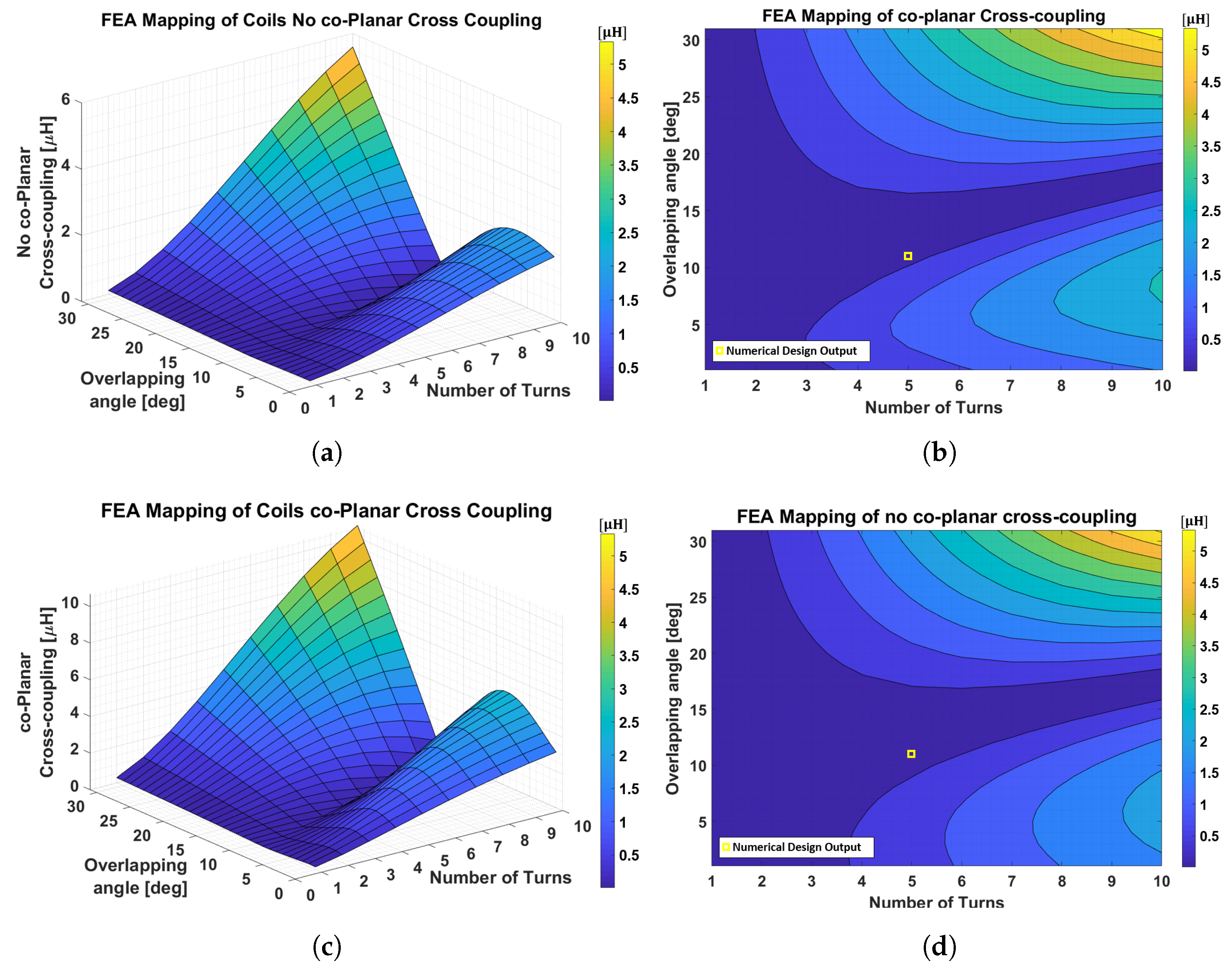
4.1. Comparison of 3D-FEA and Numerical Results

From the FEA analysis, which defined the geometry, it is possible to obtain the values of mutual inductance, self-inductance, coplanar cross-coupling inductance, and no-coplanar cross-coupling inductance as a function of the number of turns and overlapping angle as performed for the numerical model. Figure 7 shows the trends of the coplanar cross-coupling inductance and no-coplanar cross-coupling inductance. In particular, a detailed comparison has to be done considering the cross-coupling contribution at the linkage flux.
Comparing the equivalent 2D mapping of Figure 7b,d with the numerical model of Figure 5b,c, several considerations can be made.
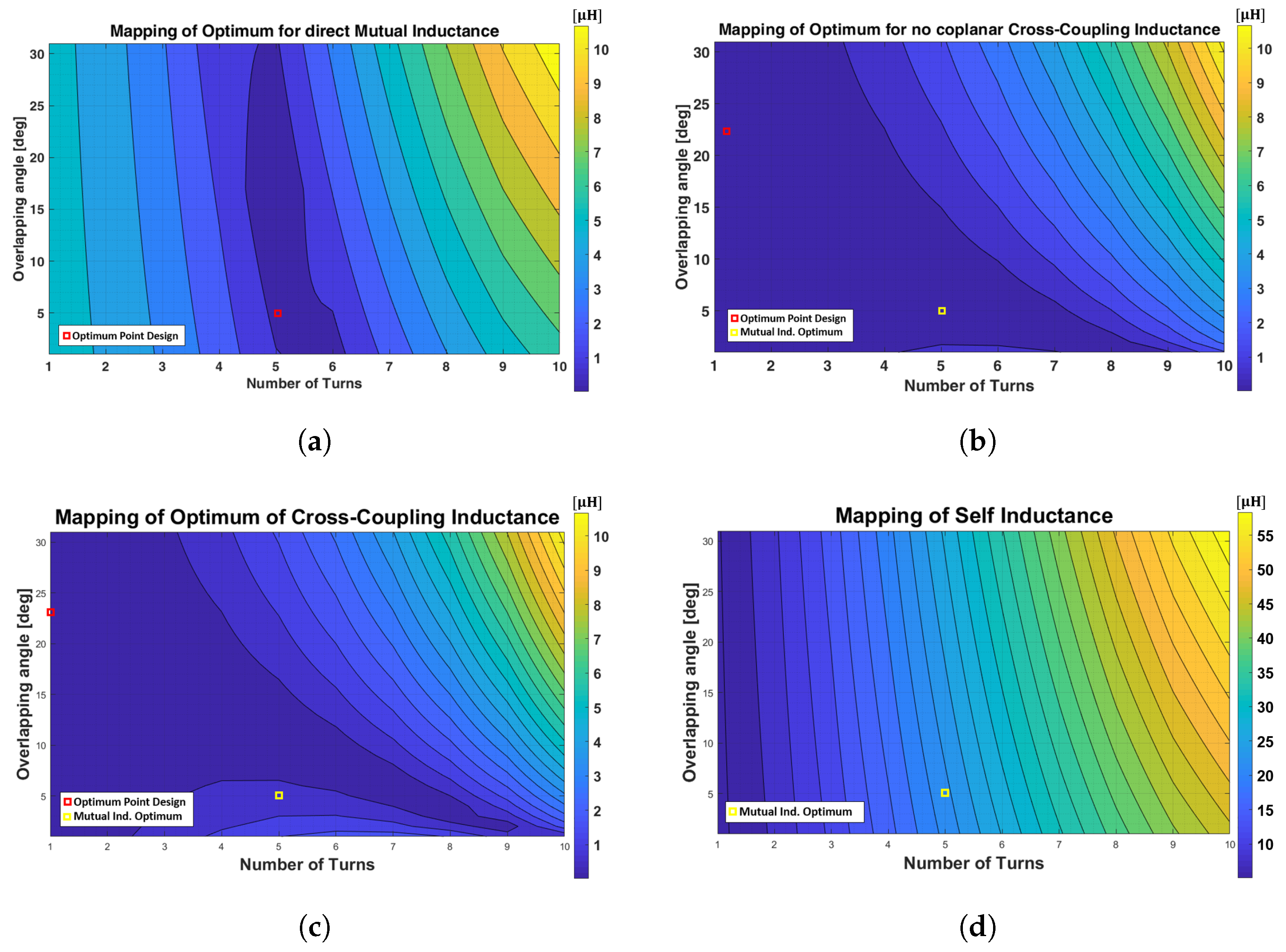
  • The general behavior of the mapping pictures is similar, but the geometry and the overlapping angle have a strong impact in terms of inductance value. This implies a differences between the numerical and the 3D-FEA analysis, especially for a high number of turns.
  • In both FEA and analytical studies, the operative point chosen lies in the area of minimum values. For completeness in Figure 7b,d in yellow, the output of the numerical model, pointed in Table 3 is highlighted.
  • Finally, considering the area of minimum values, it can be observed that there are several values of overlapping angle and number of turns that verify this criterium, as it happened, in a similar way, of the numerical study. Although, for a high number of turns, this area modifies its shape due to, as already mentioned, the difference in geometry.
Analyzing more in detail the comparison between the numerical pre-design results and the equivalent 3D-FEA solution at the target number of turns of N t u r n s = 5 , it can be seen that the differences become very small when an overlapping angle of α o v e r = [ 11 ÷ 13 ] is selected (Figure 8).
Furthermore, always referring to Figure 8, it is possible to make the following considerations:
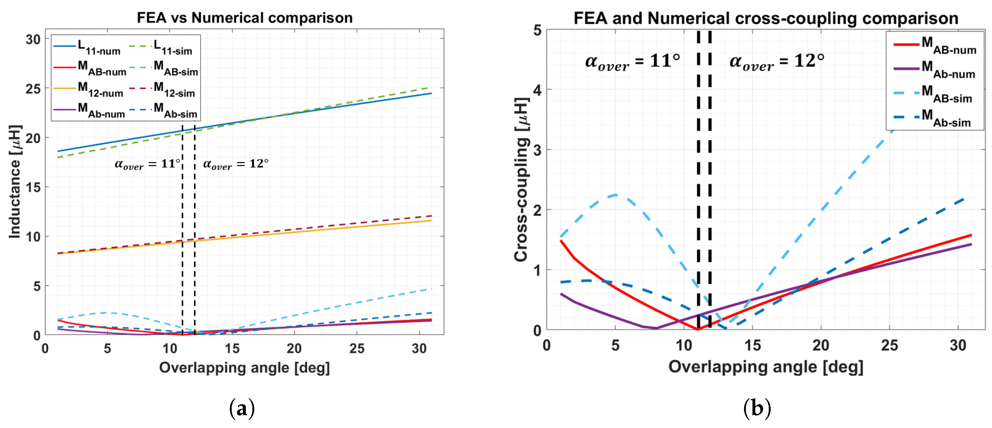
  • In Figure 8a, a comprehensive overview of the numerical and 3D-FEA results is provided to underline the small contribution of the cross-coupling effects compared to the direct mutual inductance.
  • Looking at Figure 8b, at the operating point chosen in the numerical design of α o v e r = 11 , the FEA output for co-planar cross-coupling results higher compared with the homologous from numerical design. Thus, a little variation in terms of the overlapping angle must be taken into consideration.
  • The error for the co-planar cross coupling at α o v e r = 12 , referring again to Figure 8b becomes as difference of the two studies: ε c o _ p l 252 nH.
  • The error for the non co-planar cross coupling at α o v e r = 12 becomes in terms of difference between numerical and 3D-FEA approach: ε n o C o 157 nH.
From the previous investigation, it can be deduced that the simplified geometry, for a first approach numerical design, leads to good results compared with the FEA ones.
Furthermore, until now, the computational weight in terms of machine working time has not been considered for both studies. Regarding this, a few more observations have to be reported.
  • The complete numerical analysis, for all the combinations of the number of turns and overlapping angle values, takes an approximative time of t c l k 145 s.
  • The complete finite-element design, running on the same machine of the previous study, takes an approximative time of t c l k 12 h.
  • The single FEA investigation, for a single value of the number of turns and overlapping angle, takes an approximative time of t c l k 123 s.
Thus, the numerical study is also a time-saving approach compared to a 3D-FEA complete analysis.
In Table 5, a summary of the comparison between the analytical and the 3D-FEA study is pointed out. The absolute error of the coplanar and no-coplanar cross-coupling effects in the two methods may seem high. However if the value of M A b and of M A B is compared with M 12 , obtaining h A B = M A B M 12 and h A b = M A b M 12 , the difference between the two values turns out to be Δ h A b = 1.62 % and Δ h A B = 2.62 % , respectively. Thus, as the goal is to have a minimum contribution of the cross-coupling effects onto the direct flux linkage, it can be considered that this result is adequately fulfilled. Considering the cross-coupling terms, it can be noticed that these terms result in less than the 4 % compared with the direct mutual inductance. Hence, the direct linkage flux for every single phase does not suffer from flux leakage due to the other phases. A finalized simulation model [38,39,40,41,42,43], more realistic in modeling the aluminum shield and adding the ferrites, is faced later with the purpose of reaching a final tuned design.

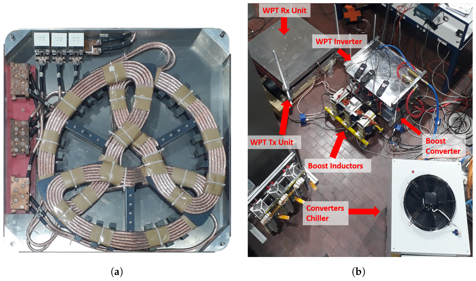
4.2. Real Case Study and Final Design

This sub-section analyzes the introduction of the problem of a key factor: the electromagnetic shielding structure. This feature has two main roles. The first is, as already mentioned, an electromagnetic shield to prevent leakage flux from linking above the EV frame and becoming harmful to human health and creating potential safety issues. The second reason is a mechanical one. The aluminum cover indeed is used as a case for the 3-Ph coil structure as well as for the compensation capacitors as the whole structure has to be placed under the chassis of the vehicle.
Looking at Table 6, it is possible to notice that the maximum value for the number of turns per coil used is N t u r n s = 6 . This choice guarantees the maximum number of turns because of the minimum curvature radius admitted. Furthermore, it can be seen that the compensation resonant tank has been adapted to the required self-inductance values in the different solutions proposed.

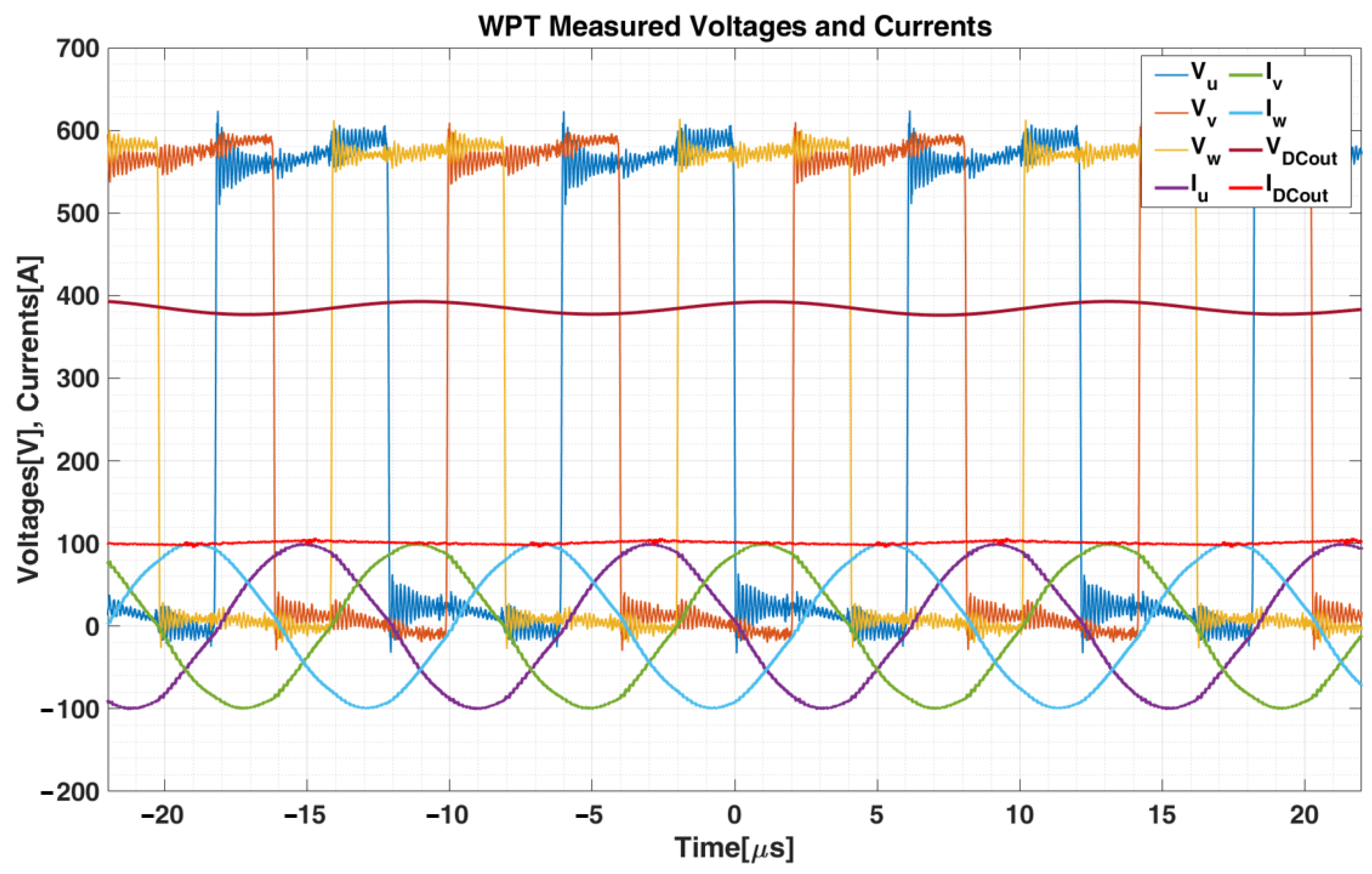
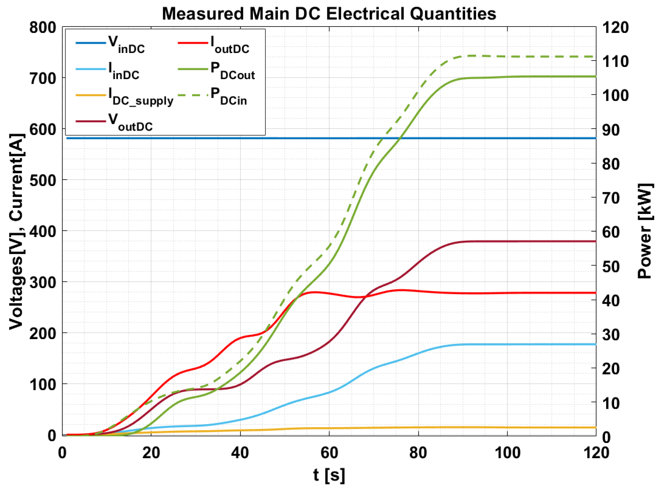
5. Experimental Validation

5.1. Experimental Setup

Prototype coils based on the topology proposed in Section 2 have been realized for experimental validation. The resulting structure can be seen in Figure 9a, where one Rx manufactured unit is displayed. The transmitter, not shown, has the same mechanical dimensions and coils shape.
In Figure 9b, the test-bench adopted for experimental validation of the numerical design proposed in Section 2 is presented. In particular, in the power bench, all the parts of the WPT system and the testing power converter used to perform the opposition-method technique are enlightened. The shown configuration has been used to test the system without the needing of a full power supply and a load capable of managing the rated power of 100 kW [23]. The chiller, shown in Figure 9b, is used as a safety backup cooling system for the power converters. Hence, since during the test, the chiller is never used actively, in the final evaluation of the DC–DC overall efficiency, the chiller losses are not taken into account. Both the WPT units, in fact, work without any forced cooling system to minimize the weight and save space inside the WPT unit case.
In Table 7, it is possible to analyze the measured values for the individual coil, in terms of self and mutual inductance, at 85 kHZ, the system working point from Table 1. These measurements are carried out through the use of an LCR METER IM3536.
Referring to the direct mutual inductance, the maximum error of the measured values compared with the numerical-design results ε M 12 11.4 % . Considering the cross-coupling effects of co-planar coils error, this turns out to be: M A B m e a s M A B n u m = ε c o _ p l 200 nH. While the no-coplanar leakage error, in terms of equivalent mutual inductance, results: M A b m e a s M A b n u m = ε N o c o p l 53 nH.
In particular, considering the cross-coupling effects, the total value in terms of weight onto the direct mutual inductance is equal to h A B = M A B M 12 3 % . This, indeed, represents a very small contribution of the leakage contributions compared with the flux linkage. Furthermore, this proves the effectiveness of the numerical design of Table 5.

5.2. Experimental Results

In this section, the experimental validation for the WPT system powered with a supply voltage set to V i n D C = 580 V is introduced, reaching the requirements and specifications of Table 1 at the very beginning of this work.
In particular, in Figure 10, the experimental outputs, in terms of currents and voltages of the AC primary side of the WPT system and the current and voltage at the equivalent output load terminals, are depicted.
In Figure 11, the main DC electrical quantities for the experimental validation of the WPT system at V i n D C = 580 V are reported. In this case, the boost-converter is set to have an output maximum operating voltage equal to the rate of equivalent battery load in Table 1. At the same time, the WPT-inverter is set to maintain full square wave phase voltages, as already described in [23].
Therefore, thanks to the previous analysis, it is possible to report all the data at a steady state for the WPT system operating at an input voltage of V D C i n = 580 V.
The reported measurements are performed through the use of a power-meter analyzer (LMG-500) equipped with three current sensors (IT205-S: for measurements up to 200 A and IT605-S: to go beyond 200 A measured) and a terminal, or equivalent PC, interface. This system is also equipped with three voltage pick-ups for the DC measurement of the system and the efficiency of the whole WPT structure from the source to the load side. The interface between the already defined current probes and the power-meter is the Multi-Channel Current Transducer System (MCTS) produced by SIGNALTEC.
In particular, taking now into account (1), it is possible to evaluate the on-field value of mutual inductance responsible for the power transferred of Table 8 and compare it with the one of the numerical-design output. This mutual inductance, which has to be intended as a mean value of inductance for the three phases, turns out to be M 12 = 8.46 μ H and, as a consequence, a total error compared with the numerical-design of ε M 12 11 % . This results in further verification of the numerical-solution approach, together with the outputs pointed out in Table 7.

6. Conclusions

In this paper, a novel numerical model based on equivalent simplified circular geometries is proposed for the design of a high power complex TPP system. It has been seen, through comparison between the analytical study and the FEA evaluation, that the approximation of using a circular geometry with the equal area responsible for the linkage flux is effective and a good starting point for a final, more accurate design. Moreover, it is in this way possible to obtain a more streamlined and less time-consuming sizing procedure compared to an analysis performed only through FEA.
Hence, with the outcomes of the numerical design it is possible to determine an algorithm that, starting from the initial constraints, allows one to obtain a preliminary structure and the optimal number of turns that permits one to transfer the requested power. At the same time a proper definition of the overlap angle ensures that different phases do not interfere with each other. In this way, the 3-Ph system becomes electromagnetically decoupled in three individual phases, so it is possible to approach the design of the single-coil as a single-phase system. Independently of this, from the point of view of the power transferred to the load, the system acts electrically as a three-phase one with the well-known related benefits.
As a further verification step, following the proposed numerical model, a prototype has been realized able to transfer 100 kW at 580 Vdc input with a DC to DC efficiency greater than 94% over 50 mm air gap in perfect alignment.
Future improvements will be oriented toward studying the system in misalignment conditions to obtain a simplified procedure for modeling the disproportion in terms of imbalance of mutual inductance between the phases. Future works could extend the procedure presented in this paper to other complex electromagnetic geometries, providing then a more general and simplified preliminary design procedure to model a multiphase WPT pad structure. Furthermore, the implementation of the system in a real case application, for EV battery charging, could lead to other considerations about the design of the WPT system.

Author Contributions

Writing—review and editing, J.C. and R.R.; supervision, P.G. All authors have read and agreed to the published version of the manuscript.

Funding

This research was funded by European Union’s Horizon 2020 research and innovation programme, namely through ASSURED project grant number 769850.

Institutional Review Board Statement

Not applicable.

Informed Consent Statement

Not applicable.

Conflicts of Interest

The authors declare no conflict of interest.

References

  1. Yilmaz, M.; Krein, P.T. Review of Battery Charger Topologies, Charging Power Levels, and Infrastructure for Plug-In Electric and Hybrid Vehicles. IEEE Trans. Power Electron. 2013, 28, 2151–2169. [Google Scholar] [CrossRef]
  2. Mohammed, S.A.Q.; Jung, J.W. A Comprehensive State-of-the-Art Review of Wired/Wireless Charging Technologies for Battery Electric Vehicles: Classification/Common Topologies/Future Research Issues. IEEE Access 2021, 9, 19572–19585. [Google Scholar] [CrossRef]
  3. Aggeler, D.; Canales, F.; Zelaya-De La Parra, H.; Coccia, A.; Butcher, N.; Apeldoorn, O. Ultra-fast DC-charge infrastructures for EV-mobility and future smart grids. In Proceedings of the 2010 IEEE PES Innovative Smart Grid Technologies Conference Europe (ISGT Europe), Gothenburg, Sweden, 11–13 October 2010; pp. 1–8. [Google Scholar] [CrossRef]
  4. Du, Y.; Lukic, S.; Jacobson, B.; Huang, A. Review of high power isolated bi-directional DC-DC converters for PHEV/EV DC charging infrastructure. In Proceedings of the 2011 IEEE Energy Conversion Congress and Exposition, Phoenix, AZ, USA, 17–22 September 2011; pp. 553–560. [Google Scholar] [CrossRef]
  5. Mahesh, A.; Chokkalingam, B.; Mihet-Popa, L. Inductive Wireless Power Transfer Charging for Electric Vehicles—A Review. IEEE Access 2021, 9, 137667–137713. [Google Scholar] [CrossRef]
  6. Ahmad, A.; Alam, M.S.; Chabaan, R. A Comprehensive Review of Wireless Charging Technologies for Electric Vehicles. IEEE Trans. Transp. Electrif. 2018, 4, 38–63. [Google Scholar] [CrossRef]
  7. Sanz, J.F.; Villa, J.L.; Sallán, J.; Perié, J.M.; Duarte, L.G. UNPLUGGED project: Development of a 50 kW inductive electric vehicle battery charge system. In Proceedings of the 2013 World Electric Vehicle Symposium and Exhibition (EVS27), Barcelona, Spain, 17–20 November 2013; pp. 1–7. [Google Scholar] [CrossRef]
  8. Bagchi, A.C.; Kamineni, A.; Zane, R.A.; Carlson, R. Review and Comparative Analysis of Topologies and Control Methods in Dynamic Wireless Charging of Electric Vehicles. IEEE J. Emerg. Sel. Top. Power Electron. 2021, 9, 4947–4962. [Google Scholar] [CrossRef]
  9. Zaheer, A.; Neath, M.; Beh, H.Z.Z.; Covic, G.A. A Dynamic EV Charging System for Slow Moving Traffic Applications. IEEE Trans. Transp. Electrif. 2017, 3, 354–369. [Google Scholar] [CrossRef]
  10. Chen, Z.; Jing, W.; Huang, X.; Tan, L.; Chen, C.; Wang, W. A Promoted Design for Primary Coil in Roadway-Powered System. IEEE Trans. Magn. 2015, 51, 1–4. [Google Scholar] [CrossRef]
  11. Thai, V.X.; Choi, S.Y.; Choi, B.H.; Kim, J.H.; Rim, C.T. Coreless power supply rails compatible with both stationary and dynamic charging of electric vehicles. In Proceedings of the 2015 IEEE 2nd International Future Energy Electronics Conference (IFEEC), Taipei, Taiwan, 1–4 November 2015; pp. 1–5. [Google Scholar] [CrossRef]
  12. Sallan, J.; Villa, J.L.; Llombart, A.; Sanz, J.F. Optimal Design of ICPT Systems Applied to Electric Vehicle Battery Charge. IEEE Trans. Ind. Electron. 2009, 56, 2140–2149. [Google Scholar] [CrossRef]
  13. Luo, Z.; Wei, X. Analysis of Square and Circular Planar Spiral Coils in Wireless Power Transfer System for Electric Vehicles. IEEE Trans. Ind. Electron. 2018, 65, 331–341. [Google Scholar] [CrossRef]
  14. Ridge, A.; Ahamad, K.K.; McMahon, R.; Miles, J. Development of a 50 kW Wireless Power Transfer System. In Proceedings of the 2019 IEEE PELS Workshop on Emerging Technologies: Wireless Power Transfer (WoW), London, UK, 18–21 June 2019; pp. 406–409. [Google Scholar] [CrossRef]
  15. Yang, Y.; Cui, J.; Cui, X. Design and Analysis of Magnetic Coils for Optimizing the Coupling Coefficient in an Electric Vehicle Wireless Power Transfer System. Energies 2020, 13, 4143. [Google Scholar] [CrossRef]
  16. Liu, X.; Hui, S.Y. Optimal Design of a Hybrid Winding Structure for Planar Contactless Battery Charging Platform. IEEE Trans. Power Electron. 2008, 23, 455–463. [Google Scholar] [CrossRef]
  17. Pries, J.; Galigekere, V.P.N.; Onar, O.C.; Su, G. A 50-kW Three-Phase Wireless Power Transfer System Using Bipolar Windings and Series Resonant Networks for Rotating Magnetic Fields. IEEE Trans. Power Electron. 2020, 35, 4500–4517. [Google Scholar] [CrossRef]
  18. Song, Y.; Madawala, U.K.; Duleepa, J.T.; Hu, A.P. Cross coupling effects of poly-phase bi-directional inductive power transfer systems used for EV charging. In Proceedings of the 2015 IEEE 2nd International Future Energy Electronics Conference (IFEEC), Taipei, Taiwan, 1–4 November 2015; pp. 1–7. [Google Scholar] [CrossRef]
  19. Song, C.; Kim, H.; Jung, D.H.; Yoon, K.; Cho, Y.; Kong, S.; Kwack, Y.; Kim, J. Three-phase magnetic field design for low EMI and EMF automated resonant wireless power transfer charger for UAV. In Proceedings of the 2015 IEEE Wireless Power Transfer Conference (WPTC), Boulder, CO, USA, 13–15 May 2015; pp. 1–4. [Google Scholar] [CrossRef]
  20. Cirimele, V.; Colussi, J.; Villa, J.L.; Ganga, A.L.; Guglielmi, P. Modelling of a 100 kW-85 kHz Three-Phase System for Static Wireless Charging and Comparison with a Classical Single-Phase System. In Proceedings of the 2020 IEEE International Symposium on Circuits and Systems (ISCAS), Seville, Spain, 12–14 October 2020; pp. 1–5. [Google Scholar] [CrossRef]
  21. Thrimawithana, D.J.; Madawala, U.K.; Francis, A.; Neath, M. Magnetic modeling of a high-power three phase bi-directional IPT system. In Proceedings of the IECON 2011—37th Annual Conference of the IEEE Industrial Electronics Society, Melbourne, VIC, Australia, 7–10 November 2011; pp. 1414–1419. [Google Scholar] [CrossRef]
  22. Kim, S.; Covic, G.A.; Boys, J.T. Tripolar Pad for Inductive Power Transfer Systems for EV Charging. IEEE Trans. Power Electron. 2017, 32, 5045–5057. [Google Scholar] [CrossRef]
  23. Colussi, J.; La Ganga, A.; Re, R.; Guglielmi, P.; Armando, E. 100 kW Three-Phase Wireless Charger for EV: Experimental Validation Adopting Opposition Method. Energies 2021, 14, 2113. [Google Scholar] [CrossRef]
  24. Ruffo, R.; Khalilian, M.; Cirimele, V.; Guglielmi, P.; Cesano, M. Theoretical and experimental comparison of two interoperable dynamic wireless power transfer systems for electric vehicles. In Proceedings of the 2017 IEEE Southern Power Electronics Conference (SPEC), Puerto Varas, Chile, 4–7 December 2017; pp. 1–6. [Google Scholar] [CrossRef]
  25. Mohan, N.; Undeland, T.M.; Robbins, W.P. Power Electronics. Converters, Applications and Design, 3rd ed.; John Wiley and Sons, Inc.: Hoboken, NJ, USA, 2003. [Google Scholar]
  26. Kassakian, J.; Schlecht, M.; Verghese, G. Principles of Power Electronics; Addison-Wesley Series in Electrical Engineering; Addison-Wesley: Boston, MA, USA, 1991. [Google Scholar]
  27. Fang, C.; Song, J.; Lin, L.; Wang, Y. Practical considerations of series-series and series-parallel compensation topologies in wireless power transfer system application. In Proceedings of the 2017 IEEE PELS Workshop on Emerging Technologies: Wireless Power Transfer (WoW), Chongqing, China, 20–22 May 2017; pp. 255–259. [Google Scholar] [CrossRef]
  28. Nguyen, V.T.; Yu, S.D.; Yim, S.W.; Park, K. Optimizing compensation topologies for inductive power transfer at different mutual inductances. In Proceedings of the 2017 IEEE PELS Workshop on Emerging Technologies: Wireless Power Transfer (WoW), Chongqing, China, 20–22 May 2017; pp. 153–156. [Google Scholar] [CrossRef]
  29. Wang, H.; Zhang, H.; Lei, Y. Analysis on wireless charging circuit characteristic under the hybrid compensation topology. In Proceedings of the 2016 IEEE 8th International Power Electronics and Motion Control Conference (IPEMC-ECCE Asia), Hefei, China, 22–26 May 2016; pp. 2450–2454. [Google Scholar] [CrossRef]
  30. Wang, Y.; Yao, Y.; Liu, X.; Xu, D.; Cai, L. An LC/S Compensation Topology and Coil Design Technique for Wireless Power Transfer. IEEE Trans. Power Electron. 2018, 33, 2007–2025. [Google Scholar] [CrossRef]
  31. Esteban, B.; Stojakovic, N.; Sid-Ahmed, M.; Kar, N.C. Development of mutual inductance formula for misaligned planar circular spiral coils. In Proceedings of the 2015 IEEE Energy Conversion Congress and Exposition (ECCE), Montreal, QC, Canada, 20–24 September 2015; pp. 1306–1313. [Google Scholar] [CrossRef]
  32. Kishan, D.; Vinod, M. Analysis of Mutual Inductance between Asymmetrical Spiral Circular Coils of WIPTS for EV Battery Charging. In Proceedings of the 2020 IEEE International Conference on Electronics, Computing and Communication Technologies (CONECCT), Bangalore, India, 2–4 July 2020; pp. 1–5. [Google Scholar] [CrossRef]
  33. Liu, S.; Su, J.; Lai, J. Accurate Expressions of Mutual Inductance and Their Calculation of Archimedean Spiral Coils. Energies 2019, 12, 2017. [Google Scholar] [CrossRef] [Green Version]
  34. Zhang, W.; Mi, C.C. Compensation Topologies of High-Power Wireless Power Transfer Systems. IEEE Trans. Veh. Technol. 2016, 65, 4768–4778. [Google Scholar] [CrossRef]
  35. Kuperman, A. Additional Two-Capacitor Basic Compensation Topologies for Resonant Inductive WPT Links. IEEE Trans. Power Deliv. 2020, 35, 2568–2570. [Google Scholar] [CrossRef]
  36. Mude, K.N.; Aditya, K. Comprehensive review and analysis of two-element resonant compensation topologies for wireless inductive power transfer systems. Chin. J. Electr. Eng. 2019, 5, 14–31. [Google Scholar] [CrossRef]
  37. Chen, Y.; Zhang, H.; Park, S.J.; Kim, D.H. A Switching Hybrid LCC-S Compensation Topology for Constant Current/Voltage EV Wireless Charging. IEEE Access 2019, 7, 133924–133935. [Google Scholar] [CrossRef]
  38. Chang, R.; Quan, L.; Zhu, X.; Zong, Z.; Zhou, H. Design of a wireless power transfer system for EV application based on finite element analysis and MATLAB simulation. In Proceedings of the 2014 IEEE Conference and Expo Transportation Electrification Asia-Pacific (ITEC Asia-Pacific), Beijing, China, 31 August–3 September 2014; pp. 1–4. [Google Scholar] [CrossRef]
  39. Rezmerita, G.; Bobaru, L.; Stanculescu, M.; Iordache, M.; Niculae, D. A self and mutual inductance calculation resonators with finite element analysis. In Proceedings of the 2017 International Conference on Modern Power Systems (MPS), Cluj-Napoca, Romania, 6–9 June 2017; pp. 1–4. [Google Scholar] [CrossRef]
  40. Lu, X.; Chen, K.; Wang, L.; Wang, X.; Liu, Q.H. Wideband Low-Frequency Design of Inductors and Wireless Power Transfer Coils Using the Mixed Finite-Element Time-Domain Method. IEEE Microw. Wirel. Compon. Lett. 2020, 30, 709–712. [Google Scholar] [CrossRef]
  41. Zhang, X.; Zhao, Y.; Ho, S.L.; Fu, W.N. Analysis of Wireless Power Transfer System Based on 3-D Finite-Element Method Including Displacement Current. IEEE Trans. Magn. 2012, 48, 3692–3695. [Google Scholar] [CrossRef]
  42. Kushwaha, B.K.; Rituraj, G.; Kumar, P. 3-D Analytical Model for Computation of Mutual Inductance for Different Misalignments With Shielding in Wireless Power Transfer System. IEEE Trans. Transp. Electrif. 2017, 3, 332–342. [Google Scholar] [CrossRef]
  43. Desmoort, A.; De Gréve, Z.; Dular, P.; Geuzaine, C.; Deblecker, O. Surface Impedance Boundary Condition With Circuit Coupling for the 3-D Finite-Element Modeling of Wireless Power Transfer. IEEE Trans. Magn. 2017, 53, 1–4. [Google Scholar] [CrossRef]
Figure 1. 3D model of the three-phase electromagnetic system taken into analysis.
Energies 15 05079 g001
Figure 2. Design model of the simplified equivalent circular TPP structure.
Energies 15 05079 g002
Figure 3. Mathematical model of two circular coil.
Energies 15 05079 g003
Figure 4. Mathematical model explanation of the TPP circular equivalent structure.
Energies 15 05079 g004
Figure 5. (a) Mapping of optimum for direct mutual inductance. (b) Mapping of optimum for cross-coupling inductance for non-coplanar coils. (c) Mapping of optimum for cross-coupling inductance for coplanar coils. (d) Mapping of self-inductance of a single coil.
Energies 15 05079 g005
Figure 6. Comparison of pre-design inductances at N t u r n s = 5 .
Energies 15 05079 g006
Figure 7. (a) FEA mapping of no co-planar coupling. (b) Comparison numerical and FEA results for no co-planar effects. (c) FEA mapping of co-planar coupling. (d) Comparison numerical and FEA results for co-planar effects.
Energies 15 05079 g007
Figure 8. (a) Comparison of FEA and numerical studies results at N t u r n s = 5 . (b) Detail of comparison of FEA and numerical studies of cross-coupling effects at N t u r n s = 5 .
Energies 15 05079 g008
Figure 9. (a) WPT manufactured RX-unit. (b) Power test-bench with WPT structure, WPT inverter, and boost converter and chiller.
Energies 15 05079 g009
Figure 10. Measured phase voltages ( V u , V v , V w ) and phase currents ( I u , I v , I w ) on the primary side and measured voltage ( V D C o u t ) and current ( I D C o u t ) at DC output DC.
Energies 15 05079 g010
Figure 11. Measured main DC electrical quantities of the WPT system at V i n D C = 580 V.
Energies 15 05079 g011
Table 1. Main design parameters of the three-phase system.
Three-Phase Problem Input Parameters
ParameterVariableValue
Working frequency f 0 85 kHz
DC input voltage V D C i n 580 V
DC output max voltage V D C o u t 380 V
Rated power transferred P D C o u t 100 kW
Coils max external diameter D c o i l s 710 mm
Transmitter-receiver air-gap z 0 50 mm
Table 2. Comparison of pre-design inductances.
Inductances Pre-Design Comparison at N turns = 5
ParameterVariable α over = 5 α over = 11
Self inductance L 11 19.43 μ H20.66 μ H
Mutual inductance M 12 8.689 μ H9.4 μ H
Coplanar cross-coupling inductance M A B 697 nH5.1 nH
No coplanar cross-coupling inductance M A b 203 nH236 nH
Table 3. Summary of the numerical pre-design.
ParameterVariableValues
Frequencyf85 kHz
Number of turns N t u r n s 5
Overlapping angle α o v e r 11
Mutual inductance M 12 9.4 μ H
Self inductance L 11 20.66 μ H
Coplanar cross-coupling inductance M A B 5.1 nH
No-coplanar cross-coupling inductance M A b 236 nH
Capacitors (SS compensation ) C s s 170 nF
Table 4. Simulation design parameters of the three-phase system.
ParameterVariableValue
Simulation frequency f s i m 85 kHz
Coils max external diameter D c o i l s 710 mm
Transmitter-receiver air-gap z 0 50 mm
Coils internal diameter r i n _ c o i l s 50 mm
Wire cross section S 56 mm2
Overlapping angle simulation α o v e r S i m [ 0 ÷ 30 ]
Number of turns per coil simulation N t u r n s _ S i m [ 1 ÷ 10 ]
Coil’s turns pitch ρ t u r n s 0 mm
Table 5. Comparison of numerical and FEA outputs at chosen operative point of N t u r n s = 5 and α o v e r = 12 .
ParameterVariableNumerical
Design
3D-FEA
Design
Error Numerical
Design
Direct mutual inductance M 12 9.49 μ H 9.65 μ H 1.66 %
Self inductance L 11 20.86 μ H 20.61 μ H 1.2 %
Coplanar cross-coupling inductance M A B 98 nH350 nH252 nF
Weight of coplanar cross-coupling on direct mutual inductance h A B 1.03 % 3.62 % 2.62 %
No-coplanar cross-coupling inductance M A b 304 nH157 nH147 nF
Weight of no-coplanar cross-coupling on direct mutual inductance h A b 3.20 % 1.62 % 1.62 %
Capacitors (SS compensation) C s s 168 nF170 nF 1.2 %
Table 6. Comparison of FEA outputs with the electromagnetic shield.
ParameterVariable N turns = 5
No Ferrite
N turns = 6
No Ferrite
N turns = 6
Ferrite
Mutual inductance M 12 5 μ H 5.79 μ H 9.53 μ H
Self inductance L 11 13.89 μ H 18.14 μ H 23.78 μ H
Coplanar cross-coupling inductance M A B 219 nH484 nH393 nH
No-coplanar cross-coupling inductance M A b 237 nH295 nH160 nH
Capacitors (SS compensation) C s s 252 nF193 nF147 nF
Table 7. Coils measure and comparison with 3D-FEA investigation.
Measures Single Frequency Spot: f 0 = 85 kHz
ParameterVariable N turns = 6
Ferrite
Error
3D-FEA
Mutual inductance (per each phase) M 12 8.61 μ H
8.88 μ H
8.33 μ H
≈10%
≈7%
≈12%
Self inductance (maximum error) L 11 23.78 μ H 2.4 %
Coplanar cross-coupling inductance (maximum error) M A B 205 nH 22 %
No-coplanar cross-coupling inductance (maximum error) M A b 183 nH 20 %
Table 8. Experimental results of the three-phase WPT system at V D C i n = 580 V.
ParameterVariableValue
Supply voltage V D C _ s u p p l y 580.49 V
Supply current I D C _ s u p p l y 14.83 A
Supply Power P D C _ s u p p l y 8.61 kW
WPT Input DC current I D C _ i n p u t 192.12 A
WPT Input Power P D C _ i n p u t 111.52 kW
WPT Output DC voltage V D C _ o u t p u t 378.87 V
WPT Output DC current I D C _ o u t p u t 277.97 A
WPT Output DC Power P D C _ o u t p u t 105.31 kW
WPT overall DC-DC efficiency η W P T 94.43%
Publisher’s Note: MDPI stays neutral with regard to jurisdictional claims in published maps and institutional affiliations.

