
Investigation on Key Parameters of N2 Injection to Enhance Coal Seam Gas Drainage (N2-ECGD)

Abstract
:1. Introduction
2. Mechanism of N2-ECGD
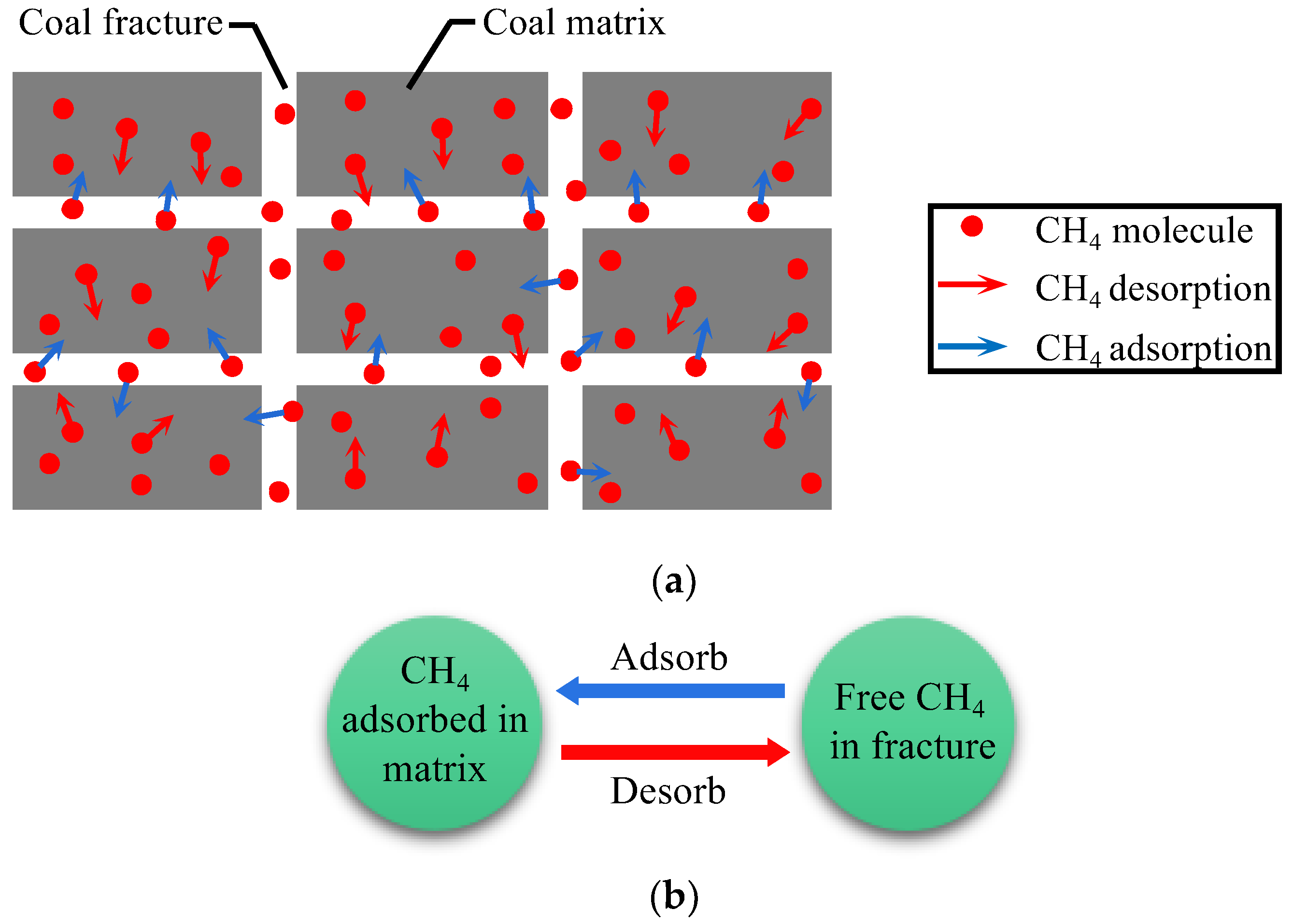
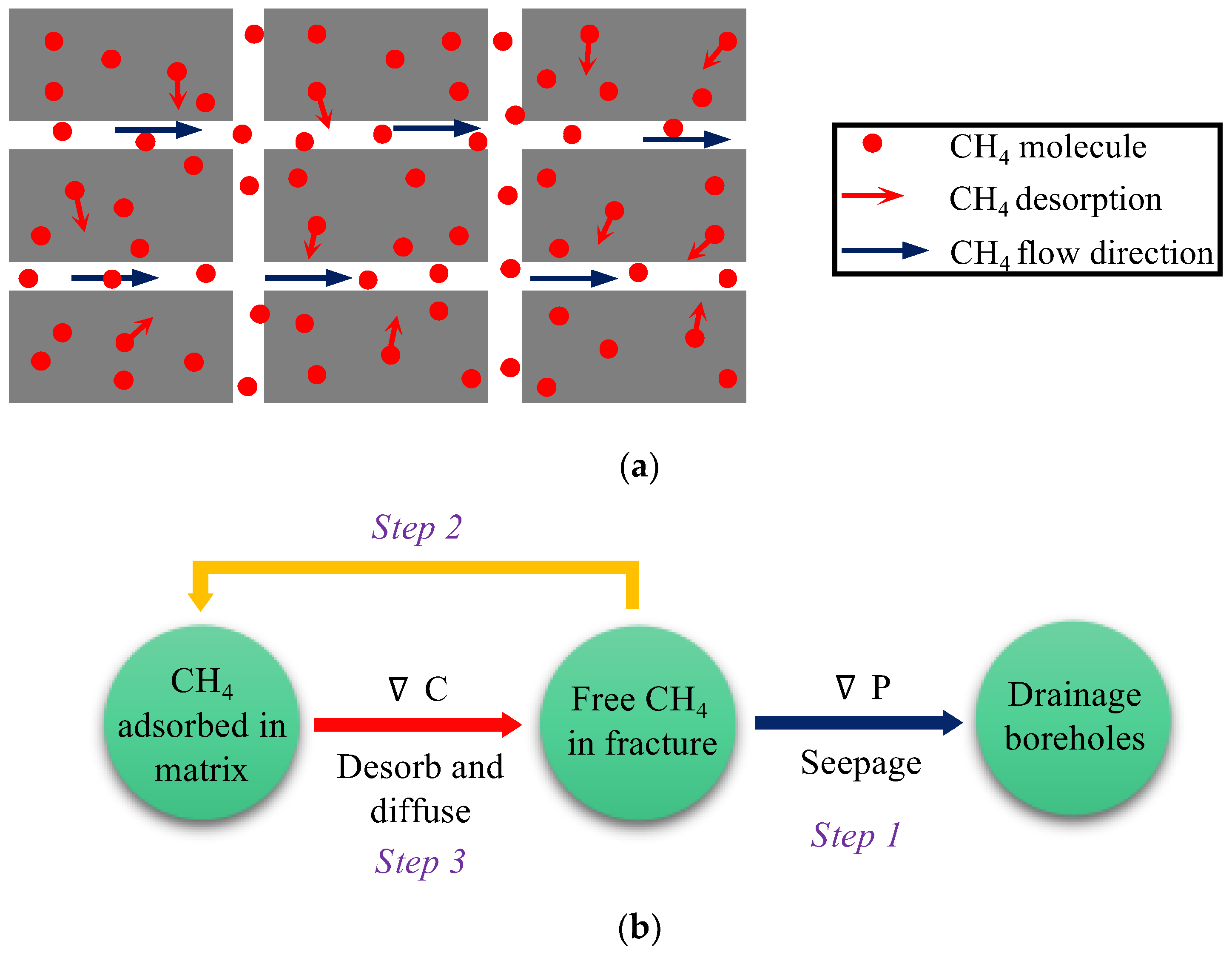
2.1. Mechanism of Gas Flow in Coal Seams
- (1)
- The gas pressure gradient promotes the fracture CH4 to flow to the borehole and reduces the overall gas pressure of the coal seam.
- (2)
- The decrease of gas pressure causes desorption and diffusion of adsorbed CH4, and the overall gas content of the coal seam decreases.
- (3)
- Coal seam permeability determines the gas flow rate under the same gas pressure gradient.
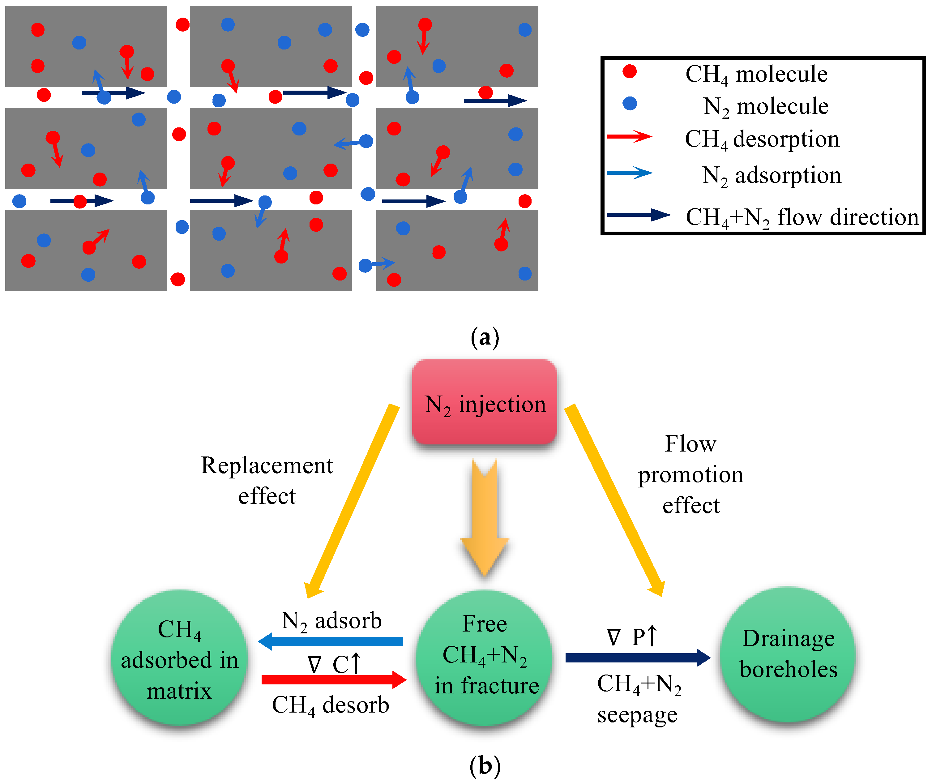
2.2. Mechanism of N2-ECGD
3. Numerical Simulation of N2-ECGD
3.1. Fully Coupled Model
3.2. Numerical Simulation
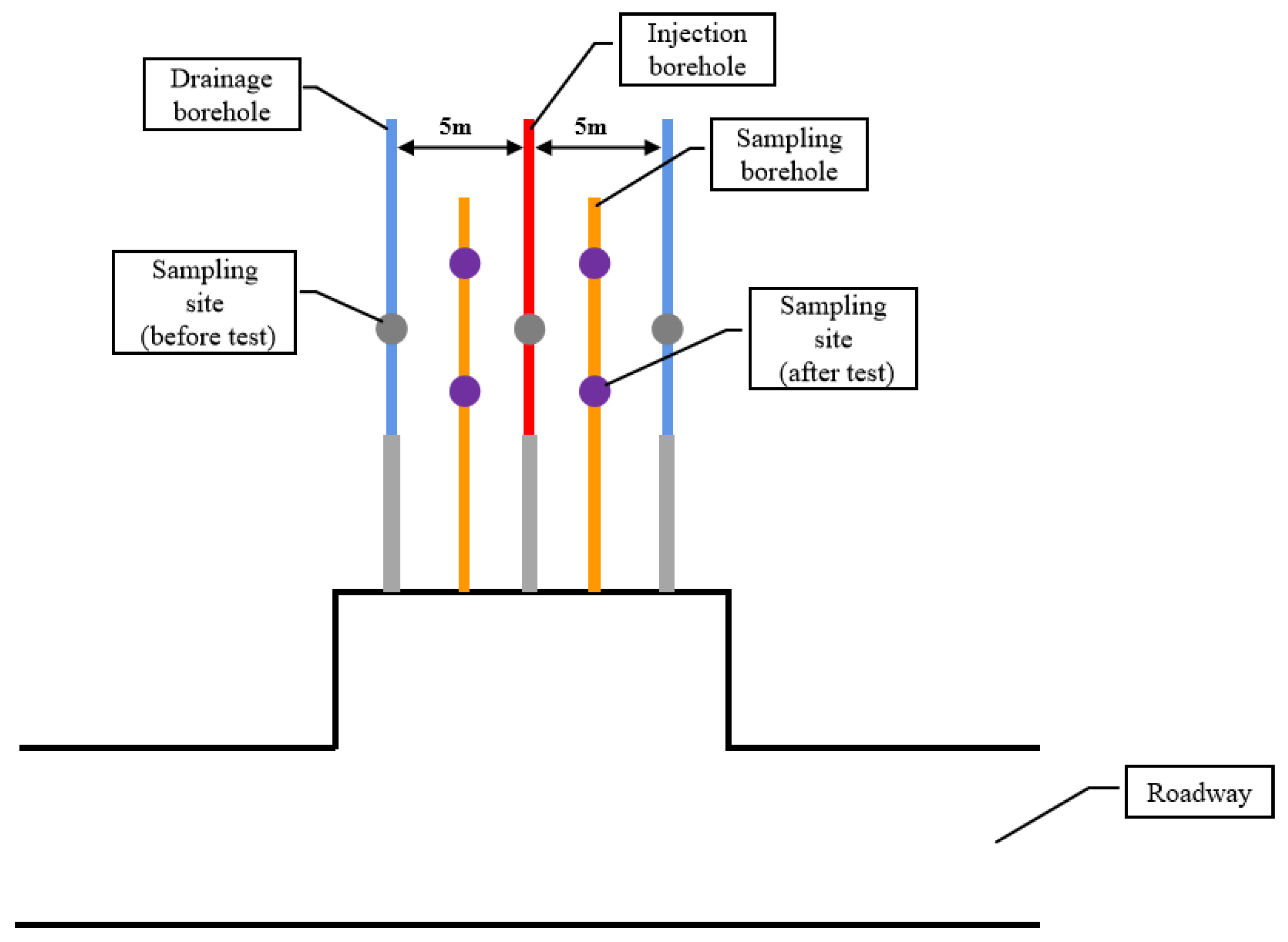
4. Field Test
4.1. Test System
4.2. Test Results
4.2.1. Drainage Parameters
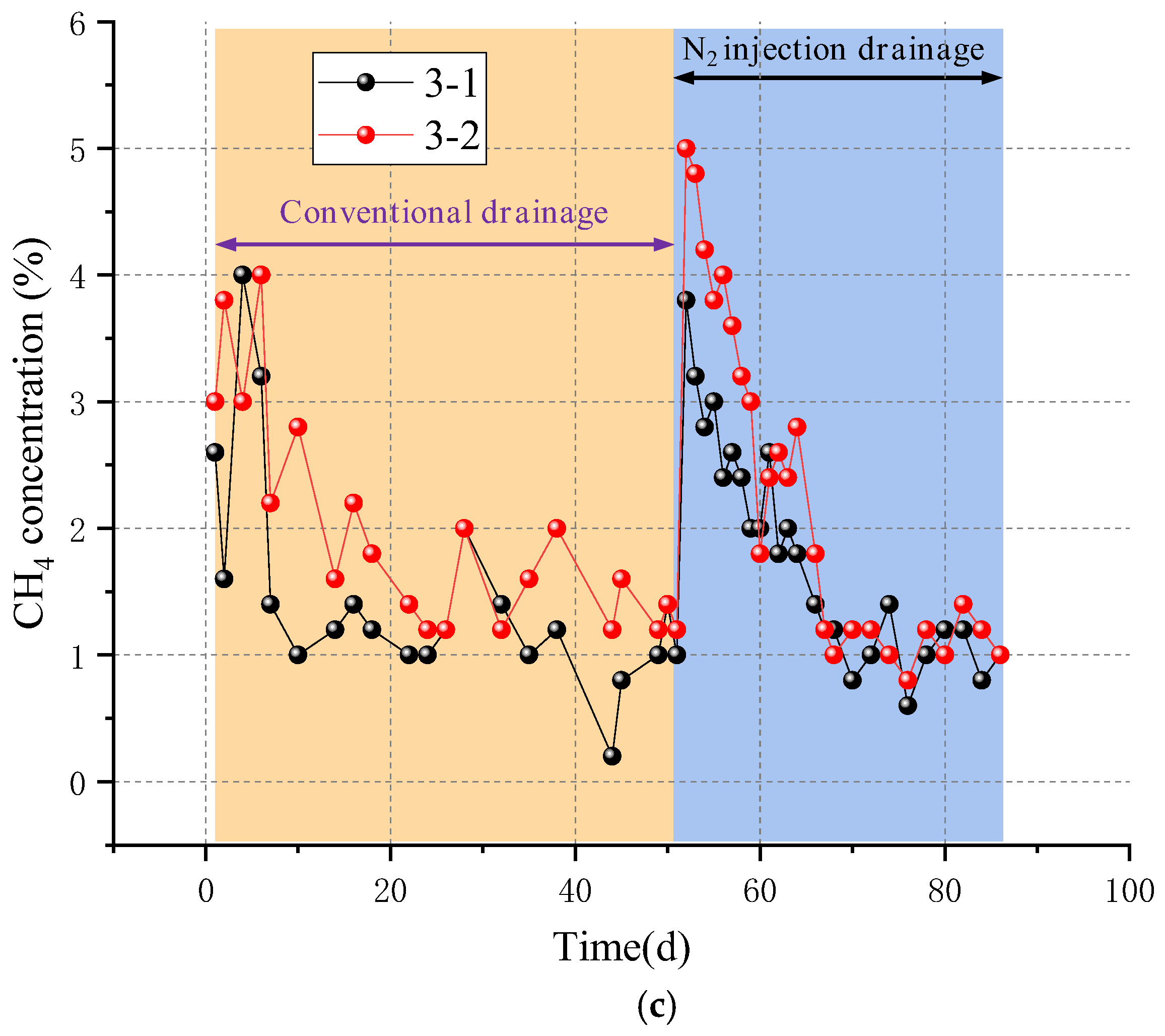
- (1)
- CH4 Concentration of Boreholes
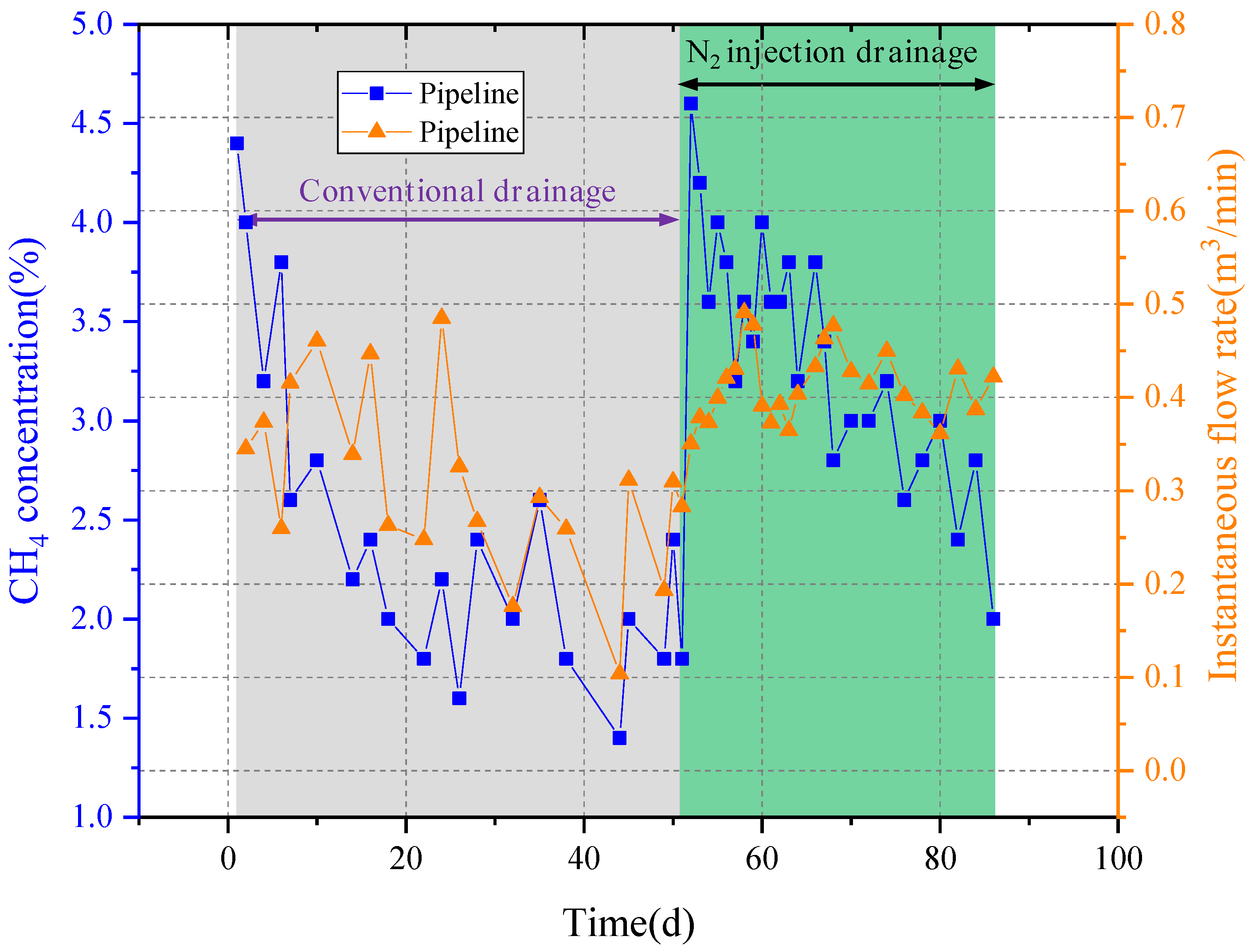
- (2)
- Drainage Parameters of Pipeline
4.2.2. Effect Verification
- (1)
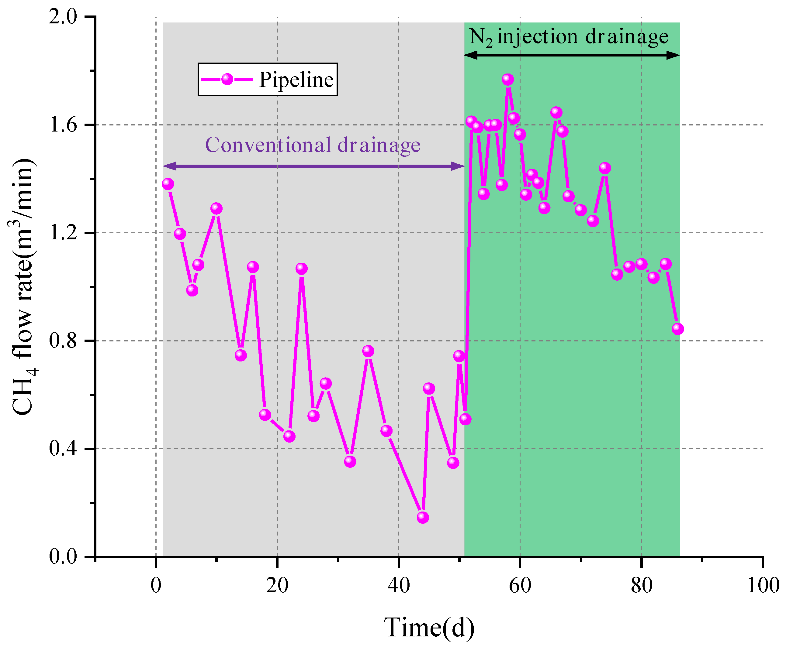
- CH4 Flow Rate
- (2)
- Gas content of Coal Seam
5. Discussion
6. Conclusions
- (1)
- N2-ECGD can play a triple effect of promoting flow, replacing, and increasing permeability, and it has obvious advantages in mechanism. The higher injection pressure can further promote the nitrogen adsorption and replace the absorbed CH4.
- (2)
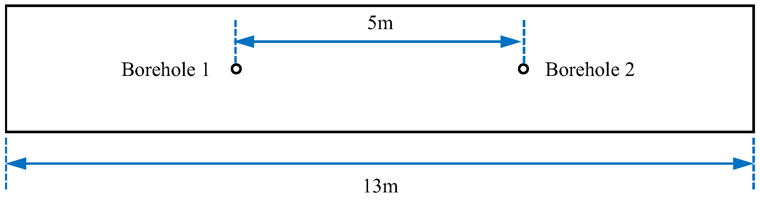
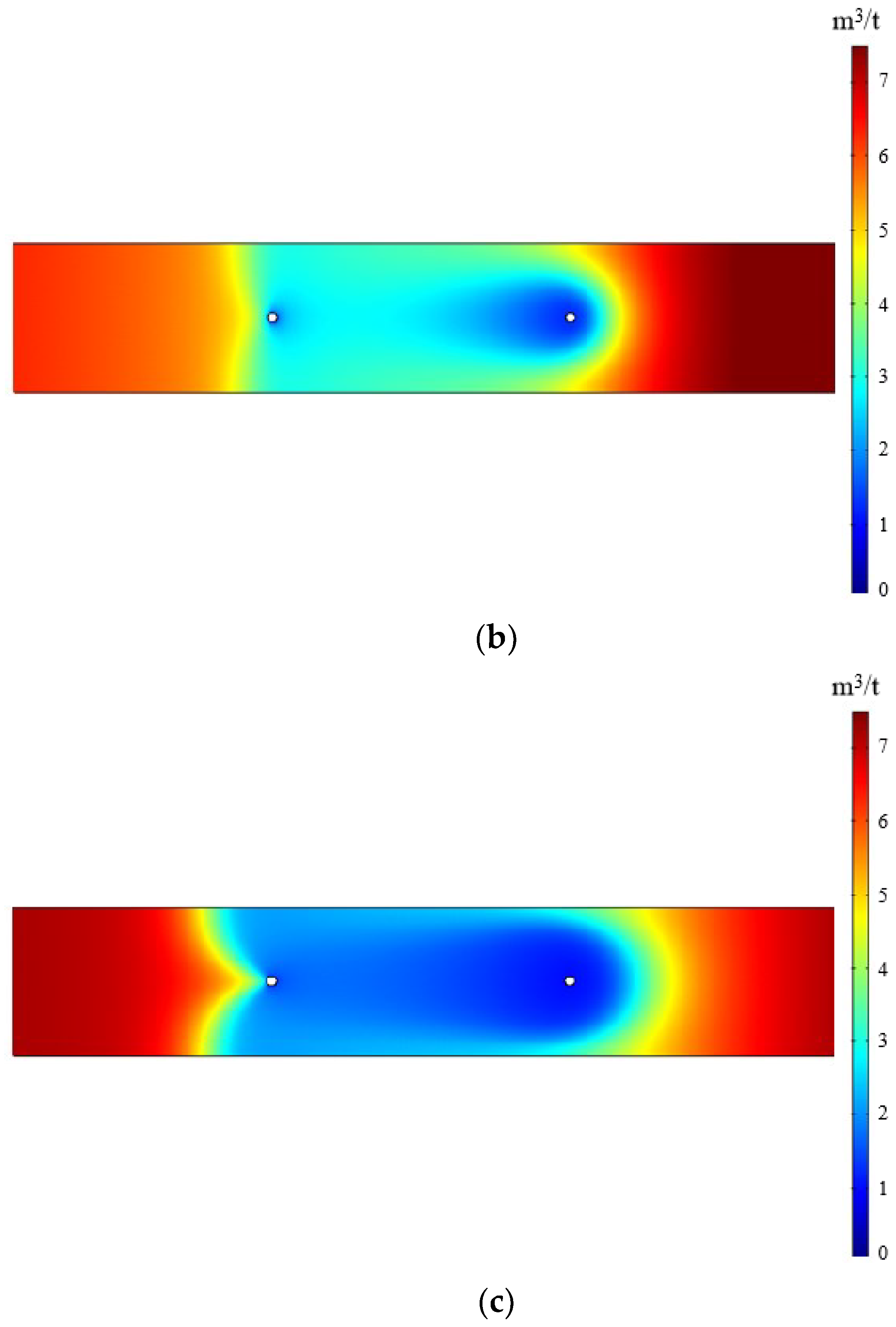
- The coupled mathematical model can quantitatively predict the effect of N2-ECGD. When the distance between injection and drainage boreholes is constant, compared with the gas injection pressure of 0.5 MPa, the effective influence area is wider when the pressure is 1.0 MPa, and the CH4 content between the two boreholes decreases more.
- (3)
- The nitrogen injection pressure has a significant influence on the concentration timeliness of the drainage borehole, and the timeliness of injection pressure at 0.4 MPa, 0.8 MPa and 1.2 MPa is 14 days, 23 days and 32 days, respectively.
- (4)
- N2-ECGD can effectively improve the gas drainage efficiency of a low permeability coal seam. The CH4 flow rate was greatly increased after the nitrogen injection. The gas content decreased by 1.94 m3/t during the injection, with a decrease of 39.73%. The efficiency was increased by 2.6–3.3 times compared with the conventional drainage.
Author Contributions
Funding
Institutional Review Board Statement
Informed Consent Statement
Data Availability Statement
Conflicts of Interest
References
- Chen, Y.; Xu, J.; Peng, S.; Yan, F.; Fan, C. A Gas–Solid–Liquid Coupling Model of Coal Seams and the Optimization of Gas Drainage Boreholes. Energies 2018, 11, 560. [Google Scholar] [CrossRef] [Green Version]
- Qu, Q.; Shi, J.; Wilkins, A. A Numerical Evaluation of Coal Seam Permeability Derived from Borehole Gas Flow Rate. Energies 2022, 15, 3828. [Google Scholar] [CrossRef]
- Xue, S.; Wang, Y.; Xie, J.; Wang, G. A coupled approach to simulate initiation of outbursts of coal and gas—Model development. Int. J. Coal Geol. 2011, 86, 222–230. [Google Scholar] [CrossRef]
- Burra, A.; Esterle, J.S.; Golding, S.D. Coal seam gas distribution and hydrodynamics of the Sydney Basin, NSW, Australia. Aust. J. Earth Sci. 2014, 61, 427–451. [Google Scholar] [CrossRef]
- Burra, A.; Esterle, J.; Golding, S.D. Horizontal stress anisotropy and effective stress as regulator of coal seam gas zonation in the Sydney Basin, Australia. Int. J. Coal Geol. 2014, 132, 103–116. [Google Scholar] [CrossRef] [Green Version]
- Wei, J.; Li, B.; Wang, K.; Sun, D. 3D numerical simulation of boreholes for gas drainage based on the pore–fracture dual media. Int. J. Min. Sci. Technol. 2016, 26, 739–744. [Google Scholar] [CrossRef]
- Dong, J.; Cheng, Y.; Jin, K.; Zhang, H.; Liu, Q.; Jiang, J.; Hu, B. Effects of diffusion and suction negative pressure on coalbed methane extraction and a new measure to increase the methane utilization rate. Fuel 2017, 197, 70–81. [Google Scholar] [CrossRef]
- Wang, L.; Lu, Z.; Chen, D.; Liu, Q.; Chu, P.; Shu, L.; Ullah, B.; Wen, Z. Safe strategy for coal and gas outburst prevention in deep-and-thick coal seams using a soft rock protective layer mining. Saf. Sci. 2020, 129, 104800. [Google Scholar] [CrossRef]
- Liu, H.; Liu, H.; Cheng, Y. The elimination of coal and gas outburst disasters by ultrathin protective seam drilling combined with stress-relief gas drainage in Xinggong coalfield. J. Nat. Gas Sci. Eng. 2014, 21, 837–844. [Google Scholar] [CrossRef]
- Liu, T.; Lin, B.; Fu, X.; Zhao, Y.; Gao, Y.; Yang, W. Modeling coupled gas flow and geomechanics process in stimulated coal seam by hydraulic flushing. Int. J. Rock Mech. Min. Sci. 2021, 142, 104769. [Google Scholar] [CrossRef]
- Lu, Y.; Wang, L.; Ge, Z.; Zhou, Z.; Deng, K.; Zuo, S. Fracture and pore structure dynamic evolution of coals during hydraulic fracturing. Fuel 2019, 259, 116272. [Google Scholar] [CrossRef]
- Chen, X.; Xue, S.; Yuan, L. Coal seam drainage enhancement using borehole presplitting basting technology–A case study in Huainan. Int. J. Min. Sci. Technol. 2017, 27, 771–775. [Google Scholar] [CrossRef]
- Puri, R.; Yee, D. Enhanced Coalbed Methane Recovery. Society of Petroleum Engineers. In Proceedings of the SPE Annual Technical Conference and Exhibition, New Orleans, LA, USA, 23–26 September 1990. [Google Scholar]
- Reeves, S.R.; Series, S.D.L. Enhanced Coalbed Methane Recovery; Society of Petroleum Engineers: London, UK, 2003. [Google Scholar]
- Busch, A.; Gensterblum, Y. CBM and CO2-ECBM related sorption processes in coal: A review. Int. J. Coal Geol. 2011, 87, 49–71. [Google Scholar] [CrossRef]
- White, C.M.; Smith, D.H.; Jones, K.L.; Goodman, A.L.; Jikich, S.A.; LaCount, R.B.; DuBose, S.B.; Ozdemir, E.; Morsi, A.B.I.; Schroeder, K.T. Sequestration of Carbon Dioxide in Coal with Enhanced Coalbed Methane Recovery A Review. Energy Fuels 2005, 19, 659–724. [Google Scholar] [CrossRef]
- Ye, J.P.; Zhang, B.; Sam, W. Test of and evaluation on elevation of coalbed methane recovery ratio by injecting and burying CO2 for 3# coal seam of north section of Shizhuang, Qingshui Basin, Shanxi. Chin. Acad. Eng. 2012, 14, 38–44. [Google Scholar]
- Packham, R.; Connell, L.; Cinar, Y.; Moreby, R. Observations from an enhanced gas recovery field trial for coal mine gas management. Int. J. Coal Geol. 2012, 100, 82–92. [Google Scholar] [CrossRef]
- Mavor, M.J.; Gunter, W.D.; Robinson, J.R. Alberta Multiwell Micro-Pilot Testing for CBM Properties, Enhanced Methane Recovery and CO2 Storage Potential. In Proceedings of the SPE Annual Technical Conference and Exhibition, Houston, TX, USA, 26–29 September 2004. [Google Scholar] [CrossRef]
- van Bergen, F.; Krzystolik, P.; van Wageningen, N.; Pagnier, H.; Jura, B.; Skiba, J.; Winthaegen, P.; Kobiela, Z. Production of gas from coal seams in the Upper Silesian Coal Basin in Poland in the post-injection period of an ECBM pilot site. Int. J. Coal Geol. 2009, 77, 175–187. [Google Scholar] [CrossRef]
- Yang, H.M.; Zhang, T.G.; Wang, Z.F.; Zhao, C.C. Experimental study on technology of accelerating methane release by nitrogen injection in coalbed. J. China Coal Soc. 2010, 35, 792. [Google Scholar] [CrossRef]
- Fang, Z.; Li, X.; Hu, H. Gas mixture enhance coalbed methane recovery technology: Pilot tests. Energy Procedia 2011, 4, 2144–2149. [Google Scholar] [CrossRef] [Green Version]
- Yang, X.; Wang, G.; Du, F.; Jin, L.; Gong, H. N2 injection to enhance coal seam gas drainage (N2-ECGD): Insights from underground field trial investigation. Energy 2021, 239, 122247. [Google Scholar] [CrossRef]
- Shi, Y.; Lin, B.; Liu, T.; Zhao, Y.; Hao, Z. Synergistic ECBM extraction technology and engineering application based on hydraulic flushing combing gas injection displacement in low permeability coal seams. Fuel 2022, 318, 123688. [Google Scholar] [CrossRef]
- Wu, Y.; Liu, J.; Chen, Z.; Elsworth, D.; Pone, D. A dual poroelastic model for CO2-enhanced coalbed methane recovery. Int. J. Coal Geol. 2011, 86, 177–189. [Google Scholar] [CrossRef]
- Liu, S.; Fang, H.; Sang, S.; Ashutosh, T.; Wu, J.; Zhang, S.; Zhang, B. CO2 injectability and CH4 recovery of the engineering test in qinshui Basin, China based on numerical simulation. Int. J. Greenh. Gas Control 2020, 95, 102980. [Google Scholar] [CrossRef]
- Fan, J.Y.; Liu, P.; Li, J.J.; Jiang, D.Y. A coupled methane/air flow model for coal gas drainage: Model development and finite-difference solution. Process Saf. Environ. Prot. 2020, 141, 288–304. [Google Scholar] [CrossRef]
- Lin, J.; Ren, T.; Wang, G.; Booth, P.; Nemcik, J. Experimental investigation of N2 injection to enhance gas drainage in CO2-rich low permeable seam. Fuel 2018, 215, 665–674. [Google Scholar] [CrossRef]
- Ren, T.; Wang, G.; Cheng, Y.; Qi, Q. Model development and simulation study of the feasibility of enhancing gas drainage efficiency through nitrogen injection. Fuel 2017, 194, 406–422. [Google Scholar] [CrossRef]
- Vishal, V.; Singh, T.; Ranjith, P. Influence of sorption time in CO2 -ECBM process in Indian coals using coupled numerical simulation. Fuel 2015, 139, 51–58. [Google Scholar] [CrossRef]
- Connell, L.; Sander, R.; Pan, Z.; Camilleri, M.; Heryanto, D. History matching of enhanced coal bed methane laboratory core flood tests. Int. J. Coal Geol. 2011, 87, 128–138. [Google Scholar] [CrossRef]
- Harpalani, S.; Schraufnagel, R. Shrinkage of coal matrix with release of gas and its impact on permeability of coal. Fuel 1990, 69, 551–556. [Google Scholar] [CrossRef]
- Wang, H.; Yang, X.; Du, F.; Wang, G.; Wang, Y.; Zhao, W.; Wang, H. Calculation of the diffusion coefficient of gas diffusion in coal: The comparison of numerical model and traditional analytical model. J. Pet. Sci. Eng. 2021, 205, 108931. [Google Scholar] [CrossRef]
- Wang, G.; Ren, T.; Qi, Q.; Zhang, L.; Liu, Q. Prediction of Coalbed Methane (CBM) Production Considering Bidisperse Diffusion: Model Development, Experimental Test, and Numerical Simulation. Energy Fuels 2017, 31, 5785–5797. [Google Scholar] [CrossRef]
- Charrière, D.; Pokryszka, Z.; Behra, P. Effect of pressure and temperature on diffusion of CO2 and CH4 into coal from the Lorraine basin (France). Int. J. Coal Geol. 2010, 81, 373–380. [Google Scholar] [CrossRef]
- Pan, Z.; Connell, L.D.; Camilleri, M.; Connelly, L. Effects of matrix moisture on gas diffusion and flow in coal. Fuel 2010, 89, 3207–3217. [Google Scholar] [CrossRef]


| Parameters | Value | Source |
|---|---|---|
| Seam thickness, m | 4 | Site data |
| Young’s modulus of coal E, MPa | 1980 | CCRI report |
| Passion’s ratio of coal , dimensionless | 0.25 | CCRI report |
| Density of coal , kg/m3 | 1400 | Lab measurement |
| Langmuir volume of CH4 VL, m3/kg | 14.2 × 10⁻³ | Lab measurement |
| Langmuir volume of N2 VL, m3/kg | 8.9 × 10⁻³ | Lab measurement |
| Langmuir pressure of CH4 PL, MPa | 0.78 | Lab measurement |
| Langmuir pressure of N2 PL, MPa | 2.12 | Lab measurement |
| Diffusion coefficient of CH4 D, m2/s | 2.8 × 10⁻¹³ | Lab measurement |
| Diffusion coefficient of N2 D, m2/s | 1.3 × 10⁻¹³ | Lab measurement |
| Porosity of coal matrix , % | 5.6 | Lab measurement |
| Gas content of methane, m3/t | 5.88 | CCRI report |
| Seam gas pressure, MPa | 0.45 | Estimation |
| Initial permeability , m2 | 8.9 × 10⁻²⁰ | CCRI report |
| Initial fracture porosity , % | 1.8 | Estimation |
| Vertical stress Sv, MPa | 10 | CCRI report |
| Horizontal stress SH, MPa | 19 | CCRI report |
| Group Number | Boreholes Number | Boreholes Depth/m | Sealing Length/m | Injection Pressure/MPa | Boreholes Spacing/m |
|---|---|---|---|---|---|
| 1 | Injection 1 Drainage 1-1 Drainage 1-2 | 100 | 20 | 1.2 | 5 |
| 2 | Injection 2 Drainage 2-1 Drainage 2-2 | 100 | 20 | 0.8 | 5 |
| 3 | Injection 3 Drainage 3-1 Drainage 3-2 | 100 | 20 | 0.4 | 5 |
| Status | Measured Value | Mean Value | Decreasing Percentage |
|---|---|---|---|
| Before N2 injection | 4.82 & 5.08 & 4.76 | 4.89 | 39.73% |
| After N2 injection | 2.98 & 2.86 & 3.12 & 2.82 | 2.95 |
Publisher’s Note: MDPI stays neutral with regard to jurisdictional claims in published maps and institutional affiliations. |
© 2022 by the authors. Licensee MDPI, Basel, Switzerland. This article is an open access article distributed under the terms and conditions of the Creative Commons Attribution (CC BY) license (https://creativecommons.org/licenses/by/4.0/).
Share and Cite
Yang, X.; Wang, G.; Ni, M.; Shu, L.; Gong, H.; Wang, Z. Investigation on Key Parameters of N2 Injection to Enhance Coal Seam Gas Drainage (N2-ECGD). Energies 2022, 15, 5064. https://doi.org/10.3390/en15145064
Yang X, Wang G, Ni M, Shu L, Gong H, Wang Z. Investigation on Key Parameters of N2 Injection to Enhance Coal Seam Gas Drainage (N2-ECGD). Energies. 2022; 15(14):5064. https://doi.org/10.3390/en15145064
Chicago/Turabian StyleYang, Xin, Gongda Wang, Mingqi Ni, Longyong Shu, Haoran Gong, and Zhie Wang. 2022. "Investigation on Key Parameters of N2 Injection to Enhance Coal Seam Gas Drainage (N2-ECGD)" Energies 15, no. 14: 5064. https://doi.org/10.3390/en15145064
APA StyleYang, X., Wang, G., Ni, M., Shu, L., Gong, H., & Wang, Z. (2022). Investigation on Key Parameters of N2 Injection to Enhance Coal Seam Gas Drainage (N2-ECGD). Energies, 15(14), 5064. https://doi.org/10.3390/en15145064