Article

Improved Whale Optimization Algorithm for Transient Response, Robustness, and Stability Enhancement of an Automatic Voltage Regulator System

1
College of Energy and Electrical Engineering, Hohai University, Nanjing 211100, China
2
School of Electrical Engineering, Southeast University, Nanjing 210096, China
3
Department of Electrical Engineering, Mehran University of Engineering and Technology, SZAB Campus, Khairpur Mirs 66020, Pakistan
4
Department of Mechanical Engineering, Mehran University of Engineering and Technology, SZAB Campus, Khairpur Mirs 66020, Pakistan
5
School of Electrical Engineering, Beijing Jiaotong University, Beijing 100044, China
6
Department of Electrical Engineering, College of Engineering, Jouf University, Sakaka 72388, Saudi Arabia
7
Department of Electrical Engineering, Faculty of Engineering, Aswan University, Aswan 81542, Egypt
*
Author to whom correspondence should be addressed.
Energies 2022, 15(14), 5037; https://doi.org/10.3390/en15145037
Submission received: 9 May 2022 / Revised: 7 June 2022 / Accepted: 8 July 2022 / Published: 10 July 2022
(This article belongs to the Special Issue Advances in Solar Energy and Materials)

Abstract

:
The proportional integral derivative (PID) controller is one of the most robust and simplest configuration controllers used for industrial applications. However, its performance purely depends on the tuning of its proportional (KP), integral (KI) and derivative (KD) gains. Therefore, a proper combination of these gains is primarily required to achieve an optimal performance of the PID controllers. The conventional methods of PID tuning such as Cohen-Coon (CC) and Ziegler–Nichols (ZN) generate unwanted overshoots and long-lasting oscillations in the system. Owing to the mentioned problems, this paper attempts to achieve an optimized combination of PID controller gains by exploiting the intelligence of the whale optimization algorithm (WOA) and one of its recently introduced modified versions called improved whale optimization algorithm (IWOA) in an automatic voltage regulator (AVR) system. The stability of the IWOA-AVR system was studied by assessing its root-locus, bode maps, and pole/zero plots. The performance superiority of the presented IWOA-AVR design over eight of the recently explored AI-based approaches was validated through a comprehensive comparative analysis based on the most important transient response and stability metrics. Finally, to assess the robustness of the optimized AVR system, robustness analysis was conducted by analyzing the system response during the variation in the time constants of the generator, exciter, and amplifier from −50% to 50% range. The results of the study prove the superiority of the proposed IWOA-based AVR system in terms of transient response and stability metrics.

1. Introduction

One of the essential control objectives of any power system is to provide a constant and stable voltage magnitude and frequency. This is because the fluctuations in voltage magnitude and frequency can degrade the performance of the connected appliances and reduce their life expectancy. Moreover, the stated parameters are directly associated with the magnitude of active and reactive powers and power loss in any power system. Therefore, a slight deviation in the voltage magnitude can generate a significant change in the magnitude of reactive power, and if it exceeds the ±5% of the rated voltage (maximum allowable voltage deviation), it reduces the life expectancy and efficiency of the connected appliances. However, unlike the non-technical losses, the loss due to technical reasons may be controlled by using proper technical measures such as regulation of voltage at different levels of the power system [1,2]. For example, the voltage of the power system can be regulated using an automatic voltage regulator (AVR) at the generation site, while the same can be done at transmission and distribution levels by using different reactive power compensation schemes and devices such as transformers, filters, and flexible alternating current transmission system (FACTS) controllers. Since the scope of this research work was purely restricted to the voltage regulation of a conventional synchronous generator at the generation side of the power system only, the voltage regulation using an optimal AVR system was considered in the current study. A simple configuration of the voltage regulation of a conventional power alternator through an AVR is pictured in Figure 1.
For regulating the generator’s output voltage, the AVR controller is used to control its excitation with an error signal that is generated by subtracting the generator’s terminal voltage from the set reference voltage. For example, if the generator’s terminal voltage falls due to the loading effect or any other reason, the magnitude of the error signal would consequently increase, which in turn increases the excitation of the generator until the terminal voltage becomes equal to the reference voltage. Once the mentioned condition is achieved, the excitation of the generator is held constant in order to supply stable voltage to all of the connected appliances. That is how this feedback control system works. Since the generator field winding possesses very high inductance and the power system experiences unavoidable load switching, it is nearly impossible to attain optimum operation of the AVR system, which is one of the very basic requirements for regulating the power system’s voltage. Generally, a PID regulator with fixed gains is utilized to improve the stability and dynamic response of an AVR due to its simple structure, robustness, and smooth implementation [4]. However, one of the major disadvantages of PID regulators that restricts their use in modern industrial and other control applications is that their performance is purely dependent on the selection of their gain values i.e., KP, KI, and KD [5,6]. The conventional methods of PID tuning, such as “trial and error”, Cohen-Coon (CC), and Ziegler–Nichols (ZN), have certain limitations. For example, “trial and error” is a very lengthy process and in the end, it does not ensure the optimal selection of the mentioned parameters. The CC and ZN methods of PID tuning select an operating point where the evaluation of the model is carried out linearly, which makes them unable to drive the optimal PID gains, and consequently the system experiences lengthy oscillations and overshoots. Furthermore, lengthy and complex calculations make it hard to explore the best combination of PID gains that provides an optimal transient response for the AVR system [3].
A few years back, researchers explored various artificial intelligence (AI) methods such as fuzzy logic (FL) and artificial neural network (ANN) to optimally tune PID controllers [7]. The major problems associated with ANN include the lengthy and time-consuming training process, while in the FL system, the generation of fuzzy membership functions depends on the proper tuning of the model, data analysis, and knowledge of the operator [8]. To avoid the stated issues, in recent years, researchers have employed recently introduced AI-based optimization techniques to achieve the optimal combination of PID controller gains in AVR systems, among which PSO is an extensively used algorithm owing to its smooth optimization process and simple implementation procedure, as can be seen in references [9,10,11,12]. However, it suffers from a few major drawbacks such as slow convergence in the optimization process, stagnation in the local optima, uncertainty in its parameter selection, and sub-optimal response in some of the very familiar benchmark functions [13]. Hence, PSO may not be a good choice when dealing with modern optimization problems [14]. Some of the familiar optimization techniques such as artificial bee colony (ABC) [15], biography-based optimization (BBO) [16], grasshopper optimization algorithm (GOA) [17] and pattern search algorithm (PSA) [18] have also been utilized in recent literature to attain an optimal transient response of the AVR system. Most recently, in July 2019, Mosaad et al. [19] studied the optimal design of the AVR by using the whale optimization algorithm (WOA). WOA is considered an efficient meta-heuristic optimization algorithm due to its simple and effective optimization procedure. However, WOA encounters a few challenges regarding its basic convergence behavior. Especially when solving multimodal problems, WOA converges quickly during the exploration phase of its operation, while it gets trapped into local solutions during exploitation. This is because the algorithm lacks adequate global exploration capability to escape the local optima. To overcome the mentioned problem in the WOA searching mechanism, an improved version called the improved whale optimization algorithm (IWOA) was presented by Xiong et al. [20]. The IWOA can balance the exploitation versus exploration better than its original version by using a dual prey searching approach, which improves its performance significantly. Further details of the IWOA are given in Section 3 of this article.
This paper attempts to obtain optimal parameters for the PID controller by using the intelligence of IWOA for the AVR system. The key objective is to improve the stability, dynamic response and robustness of the proposed AVR system. The transient response assessment is made based on percentage overshoot (%Mp), peak time (tp) settling time (ts) and rise time (tr), which are then compared with the corresponding parameters of the recently employed optimization techniques in the literature. The robustness and stability assessment of the presented AVR design is carried out in order to validate the effectiveness of the IWOA-based PID tuning method. The outcomes of the comparative analysis prove that the IWOA outperforms all of the studied competitive optimization algorithms in providing the most optimal combination of the PID gains for the considered AVR system.
The section-wise arrangement of the manuscript is given as follows. In Section 2, the mathematical foundation of the AVR system is laid out. Section 3 provides the basics of the proposed IWOA along with its classical WOA version and optimization features. Section 4 is dedicated to the fitness function opted for in the current study and its main justification. In Section 5, the outcomes of the study are provided along with their detailed analysis. Finally, Section 6 presents the conclusion of the overall study.

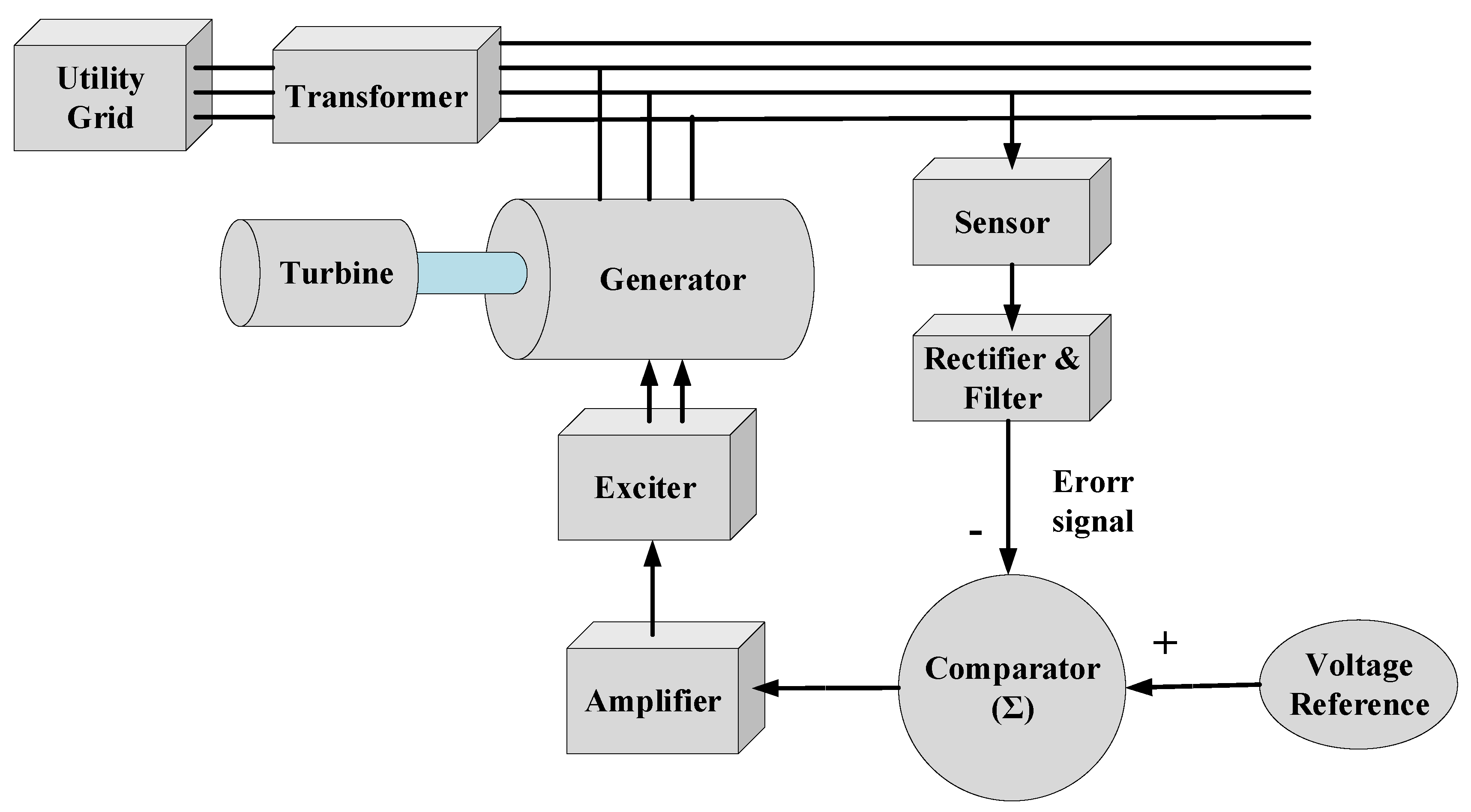
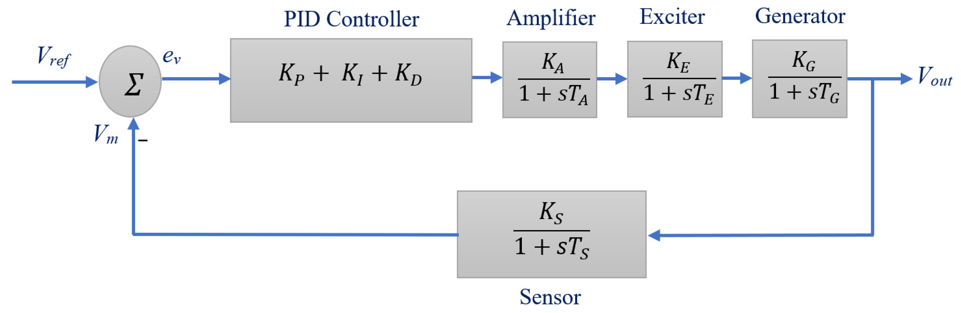
2. Mathematical Modeling of the AVR System

In this section, the considered AVR system’s transfer function (TF) modeling in the complex frequency domain is carried out. The major components of AVR, such as generator, sensor, exciter, and amplifier, are treated as linear components to ease their transfer function modeling process. As such, the transfer function of an amplifier is characterized by a time constant (TA) and a gain (KA), as depicted in Equation (1) [11].
G A ( s ) = K A 1 + s T A
Likewise, Equation (2) represents the transfer function of exciter using a time constant (TE) and a gain (KE) [11].
G E ( s ) = K E 1 + s T E
Similarly, the transfer function model of the generator can be depicted in Equation (3) with a time constant (TG) and a gain (KG) [11].
G G ( s ) = K G 1 + s T G
The sensor can also be represented by a time constant (TS) and gain (KS) using a first-order system equation as depicted in Equation (4) [11]
G S ( s ) = K S 1 + s T S
Finally, Equation (5) depicts the mathematical model of a PID controller in the complex frequency domain, as below.
G P I D ( s ) = K P + K I s + K D s
Figure 2 depicts an AVR system with its first-order transfer function components.
Solving the overall TF model by taking its output versus input ratio, the following result can be obtained,
G ( s ) = G P I D ( s ) · G A ( s ) · G E ( s ) · G G ( s ) 1 + G P I D ( s ) · G A ( s ) · G E ( s ) · G G ( s ) · G S ( s )
where G(s) denotes the transfer function of the complete AVR system.

3. IWOA along with Its Implementation

In this section, a detailed background and mathematical modeling of the IWOA along with a step-by-step methodological procedure for its implementation in the studied AVR model are provided. Initially, the optimization mechanism of WOA is explained with the help of its mathematical equations. Afterward, the logical reasoning behind the formation of the IWOA is discussed, followed by a few important highlights of the improvements that were made in the original WOA. Finally, the methodology for implementing IWOA to solve the current optimal AVR design optimization problem is discussed in detail.

3.1. Whale Optimization Algorithm

WOA is a bio-inspired stochastic swarm intelligence-based optimization technique whose functioning depicts the conduct of humpback whales. To search for food, these whales follow a special behavior called the bubble-net feeding method [21]. This food searching method of whales is based on bubble creation by encircling through a ‘9’shaped path [22]. Mathematically, this searching behavior is modeled by two phases, as described in the subsequent subsection.

3.1.1. Finding and Encircling Prey

The prey finding mechanism can be modeled by utilizing Equations (7) and (8) [23];
D = | C · X r i X i |
X i + 1 = X r i A · D
where i represents the current iteration number and is the random whale position, while C and A are the vector coefficients, calculated as
A = 2 · a · r a
C = 2 · r
where ‘a’ is the value that decreases from 2 to 0 linearly, and ‘r’ denotes a random number whose value lies between 0 and 1.
X i + 1 = X B A · D
where X represents the position vector, while XB denotes the best position vector attained so far. In this case, if A ≥ 1, the search for prey will be expressed by Equations (7) and (8), otherwise Equations (10) and (11) are used for encircling prey by a shrinking mechanism.

3.1.2. Spirally Updating Position

The updating of position can be represented by Equation (12).
X i + 1 = { X B A ^ · D i f p < 0.5 D · e b l · cos ( 2 π l ) + X B i f p 0.5
where ‘p’ and ‘l’ denote random numbers with a value ranging from 0 to 1, while ‘b’ denotes the spiral shape constant.

3.2. Improved Whale Optimization Algorithm

The indigenous WOA is one of the most efficient optimization algorithms due to its simple and effective optimization mechanism. However, WOA encounters a few challenges regarding its basic convergence behavior. Especially when solving multimodal problems, WOA converges quickly during the exploration phase of its operation, while it gets trapped into local solutions during exploitation. This is because the algorithm lacks adequate global exploration capability to escape the local optima. The authors in reference [20] worked to find the core reasons for the mentioned problems and came up with an amicable solution. They calculated the probability of selection and probability of performing for Equation (11) and found that the quoted equation has a higher probability of being selected even in the initial phase (1st half) of the optimization process. Furthermore, under the condition of p < 0.5, the total performing probability of Equation (11) was found to be much higher (i.e., 0.847) throughout the complete iterative process. Hence, Equation (11) is largely dominant over Equation (8), which leads the algorithm to converge prematurely and consequently causes its trapping into local optima. To overcome the stated issues in the original version of the WOA, the authors modified the original version of the WOA by replacing Equation (8) with Equation (13) and Equation (11) with Equation (14), as follows,
X i + 1 = X r 1 i A · | X i X r 1 i |
X i + 1 = X r 2 i A · | X B i X r 2 i |
where r1 and r2 are random numbers. Further details of IWOA can be found in reference [20].

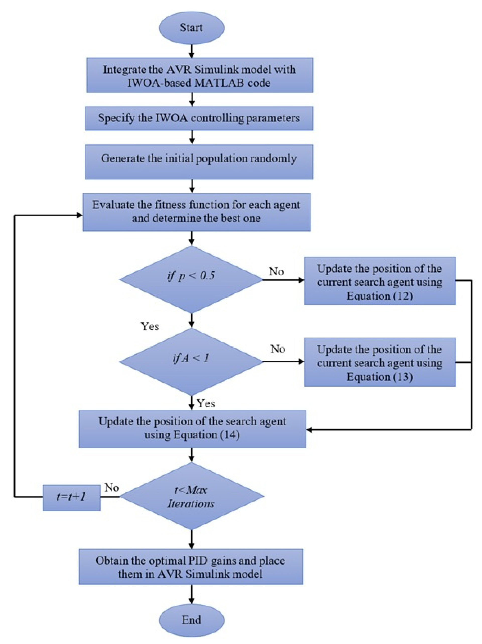
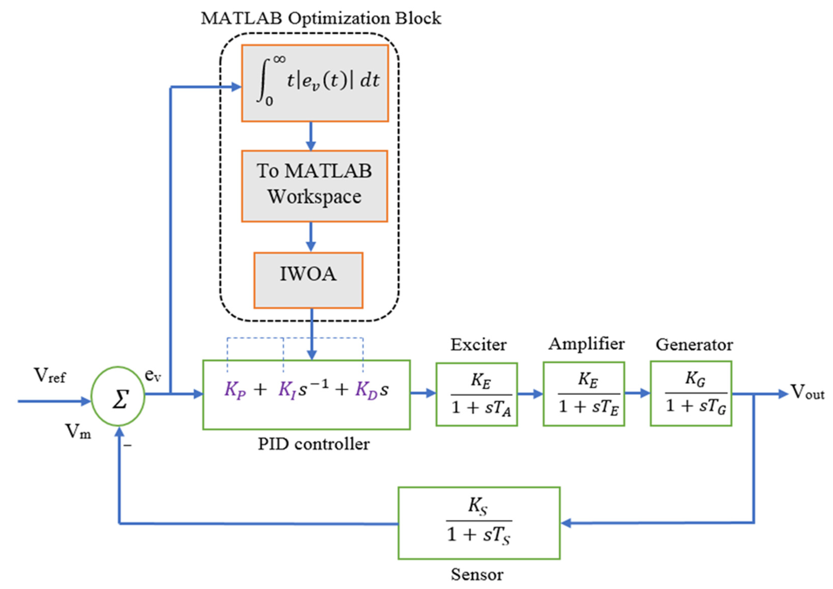
3.3. Methodology for Employing IWOA in Optimal Design of AVR System

A comprehensive flowchart of the IWOA implementation for the optimal design of an AVR system is pictured in Figure 3.
Like other meta-heuristic algorithms, the IWOA spreads some searching agents randomly within a definite search boundary. Based on the updating equations, these search candidates are then allowed to move in the given search boundary to optimize the given fitness function (FF). At the end of the optimization process, the displayed optimized parameters in the MATLAB workspace are inserted into the SIMULINK PID controller block to record the optimized transient response of the studied AVR system. The authors in reference [20] proved the superior optimization capabilities of IWOA by conducting a series of benchmark tests. The mentioned research work compared the IWOA’s solution quality and convergence speed with a few other familiar optimization techniques and concluded that the IWOA outperforms all other optimization methods in balancing its exploitation versus exploration properties, thus providing the most optimal solution, which in turn became the inspiration behind carrying out the current study.

4. Optimal Fitness Function

The selection of an appropriate FF is a very important task when solving an optimization problem. The optimization algorithm minimizes or maximizes the FF to achieve the pre-defined goals of the study [24,25]. Since the current study considers the optimal design of an AVR system by selecting an optimal combination of PID gains, the most suitable FF is an integral time absolute error (ITAE). This is because the ITAE is most extensively applied in the literature due to its easy implementation, genuine error indexing, and improved results compared to its competitors, such as integral time square error (ITSE), integral absolute error (IAE), and integral square error (ISE) [26,27,28]. The ITSE and ISE are unrealistic results due to squaring of the error and are considered violent FFs. Moreover, the IAE does not provide the true error indexing as it does not consider the time factor. Mathematically, the ITAE is defined as per Equation (15).
I T A E = 0 t | e v ( t ) | d t
where t refers to the simulation time, while ev(t) is the error obtained by subtracting the measured voltage from the set reference voltage. The overall block diagram of the proposed IWOA-based optimal selection of PID gains in an AVR system is depicted in Figure 4.
It is important to mention here that, since the FF is an error-integrating expression, its most minimized value will correspond to the most optimal design of the studied AVR system. In other words, the smaller the magnitude of the FF, the smaller will be the voltage overshoot and settling time. The code for the IWOA along with the optimization parameters such as population size, number of iterations, and number of dimensions is written in the MATLAB (2018a version) Editor window while the model for the AVR along with the considered FF is developed in SIMULINK. Once the IWOA code is executed from the MATLAB Editor, the algorithm will place the random values of PI gains within the pre-specified parameters’ boundaries. The upper and lower limit for all of the optimization variables (KP, KI, KD) are set as 0.1 and 2, respectively. Afterward, based on the randomly assigned values of the gains, the magnitude of the FF is recorded and updated continuously until the pre-set number of iterations is reached. Throughout this iterative process, the algorithm will update the existing recorded value of FF only if the newer value of the FF is less than the previously recorded value, otherwise it will keep the previous FF value. This is called the minimization process, which provides the least possible value of FF once the termination criterion (pre-set iteration number in this case) of the optimization process is met. Finally, once the pre-defined number of iterations is completed, the optimal values of the PID controller parameters are adopted from the MATLAB command window or workspace and are inserted into the PID block of the AVR SIMULINK model to record the results.
It is worthwhile to mention here that the optimization problem considered in this article is continuous and unconstrained with defined boundaries for the optimization variables. Since there exists no defined (exact) relation between the formulated fitness function (ITAE) and the optimization variables (KP, KI, KD) for their considered range, it is very difficult to provide an exact mathematical model for their relation. This is one of the reasons an analytical solution to the considered optimization problem is very difficult; hence, the authors explored a swarm intelligence-based optimization approach where a system can be treated as a black box and no exact relation between design variables and the fitness function is required. The proposed optimization method will provide the most optimal combination of PID gains (KP, KI, KD) for which the value of the formulated FF will be minimum (ideally zero). In other words, the most optimal PID gain values will occur at the least value of ITAE, which in turn corresponds to the output voltage curve of minimum overshoot and settling time.

5. Results with Interpretation

To attain the optimal response of the considered AVR, the PID gains are tuned in this paper via the IWOA. The outcomes of the study are divided into four major categories, i.e.,:
  • Performance evaluation of the IWOA based on convergence speed and solution quality.
  • Evaluation of the dynamic response of the proposed system and its comparison with other well-known methods on identical conditions and system configurations.
  • Stability assessment of the presented IWOA-based AVR system.
  • Robustness assessment of the proposed system.
The computer on which the simulations are performed is an Intel Core™ i7 with a 2.77 GHz processor. The MATLAB/SIMULINK version 2018a is utilized as the simulation tool for the current study. Furthermore, the number of search agents and the iterations are set at 50 each. In order to commence a fair comparison, the authors used the best (minimized) value of the fitness function for both algorithms over 20 runs. No stopping criterion is set except the total number of iterations.

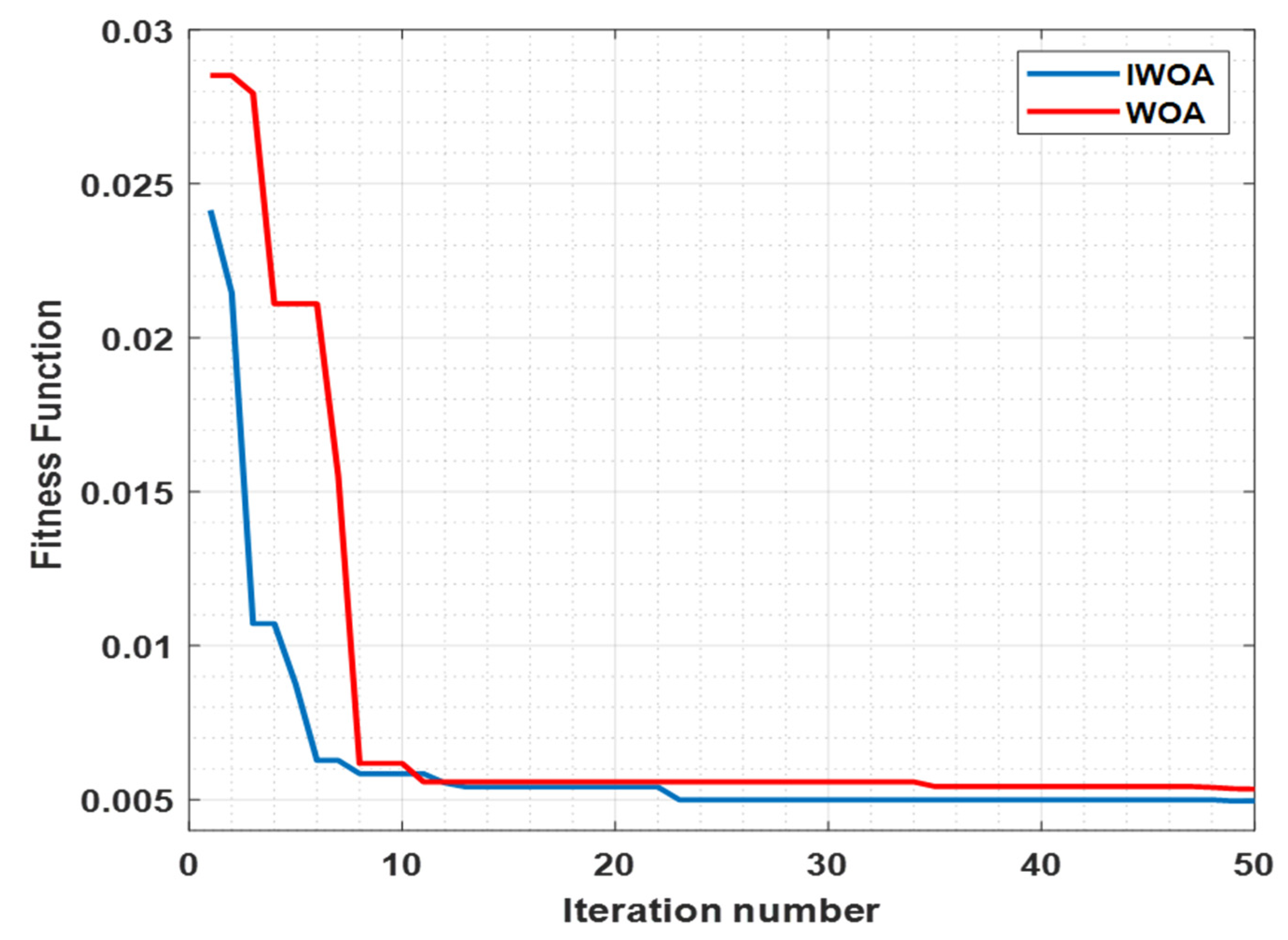
5.1. Performance of the Proposed IWOA in Optimal AVR Design

The major goal of exploring the IWOA in the AVR is to attain an optimal response of the considered system by using an optimal combination of the PID gains. To achieve the mentioned aim successfully, an automatic minimization process of an error integrating FF is carried out by using the proposed algorithm. One of the most important performance evaluation metrics of an optimization algorithm is its “convergence profile”. It is a plot between the magnitude of the considered FF versus the growing iteration number. The convergence profile for the IWOA, as compared to its original WOA version, for the studied optimization problem is presented graphically in Figure 5.
To assess the convergence rate and solution quality of the IWOA impartially, its convergence behavior is compared with that of the original WOA version for identical system parameters and FF. The results of the comparative analysis are presented in tabular form in Table 1.
Compared to the original version of WOA, its improved version provides superior convergence behavior and solution quality. To assess the performance of any optimization algorithm, the solution quality and the convergence speed are very important parameters. The quality of the solution is generally judged by recording the ultimate maximized or minimized value of the FF obtained at the end of the simulation. On the other hand, the convergence rate is evaluated by measuring the speed of the convergence, that is, how many iterations an algorithm takes to converge to its most optimal value. Since the current study considers the minimization of the FF, the smaller the ultimate attained value of FF, the greater will be the solution quality and consequently the superior will be the dynamic behavior of the considered studied AVR system. Similarly, the higher the rate of convergence, the fewer will be the number of iterations needed for reaching the most optimal solution [6]. It can be observed from Table 1 that, in comparison to the original version of WOA, its improved version IWOA requires fewer iterations to reach the minimum value of FF, which validates the superior optimizing capabilities of IWOA over its original version for the optimal AVR design.

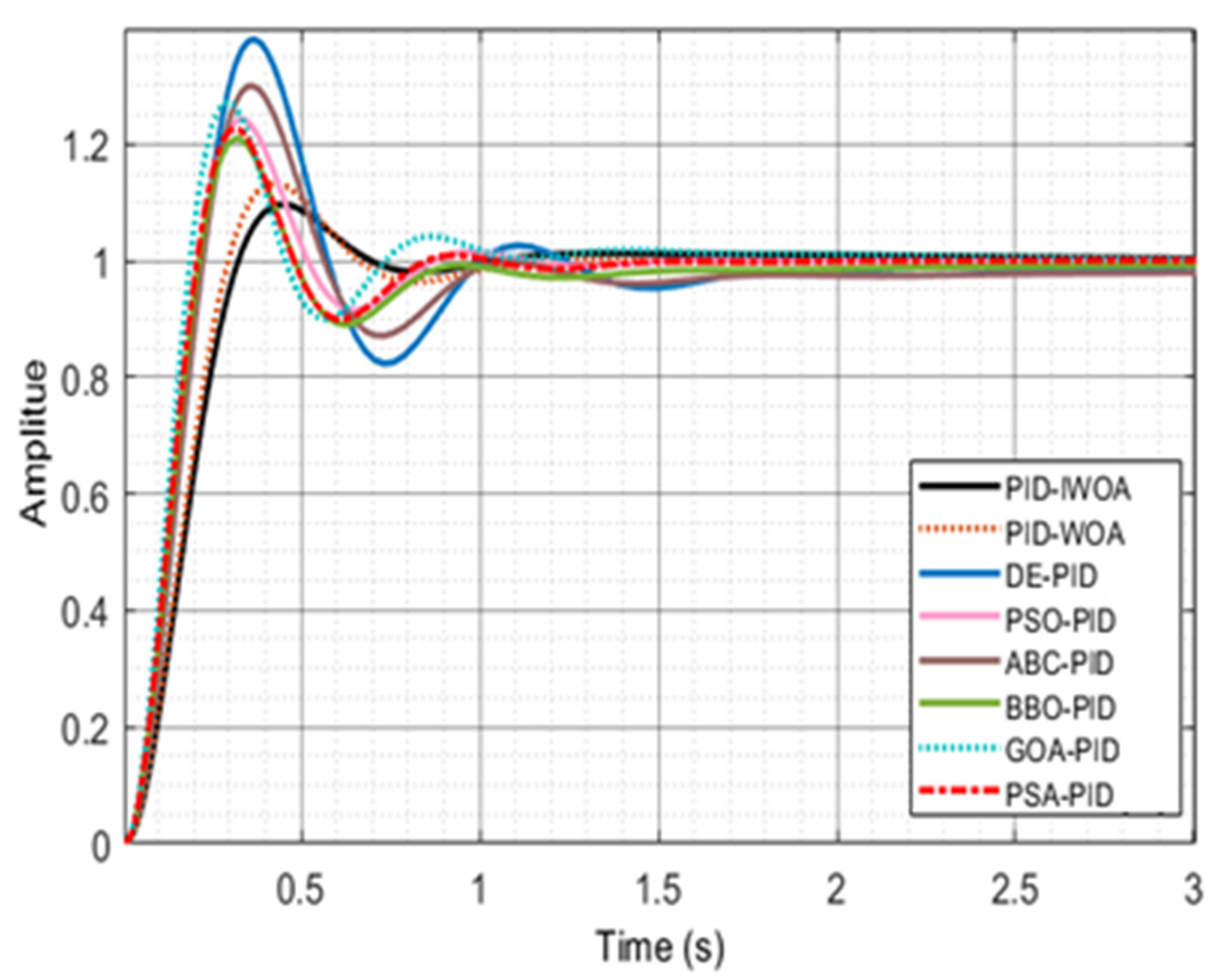
5.2. Dynamic Response Assessment

The optimized PID gains attained after the simulation are; KP = 0.816674711570196, KI = 0.689798128246624 and KD = 0.27998478993232. By inserting the obtained gains in Equation (6), the following transfer function is obtained.
V o u t ( s ) V r e f ( s ) = 0.028 s 3 + 2.882 s 2 + 8.236 s + 6.898 0.0004 s 5 + 0.0454 s 4 + 0.555 s 3 + 4.31 s 2 + 9.167 s + 6.898
To analyze the dynamic response of the proposed AVR system with a given transfer function, a unit step signal is used as an input source. Figure 6 shows the response of the system to a unit step input signal. In this research work, the key dynamic response indicators such as maximum overshoot, rise time, peak time, and settling time are adopted for analysis and comparison purposes and, as per Figure 7, their values for the proposed IWOA-AVR system are 9.56%, 0.212 s, 0.439 s and 0.642 s, respectively. To emphasize the importance of the IWOA-based AVR design, the attained results are compared against some of the familiar optimization techniques explored recently and are graphically pictured in Figure 7.
An assessment and comparative analysis of the proposed technique, in AVR application, with other familiar PID tuning techniques available in the recent literature has been carried out based on the rise time, percentage overshoot, peak value, peak time, and settling time, and the achieved outcomes are presented in Table 2.
Figure 7 and Table 2 verify that the IWOA-AVR system offers the closest solution to the optimum amongst all studied algorithms for the same cause. For example, the IWOA-based AVR model provide 6.30941%, 70.9013%, 49.1984%, 68.2005%, 61.7709%, 38.3969%, 53.4354% and 43.2469% less overshoot than WOA, DE [15], PSO [9], PSO [15], ABC [15], BBO [16], GOA [17] and PSA [18] respectively. Therefore, the proposed optimization algorithm-based AVR design duly authenticates its superior performance over the other well-known algorithm-based studies for the identical system parameters.

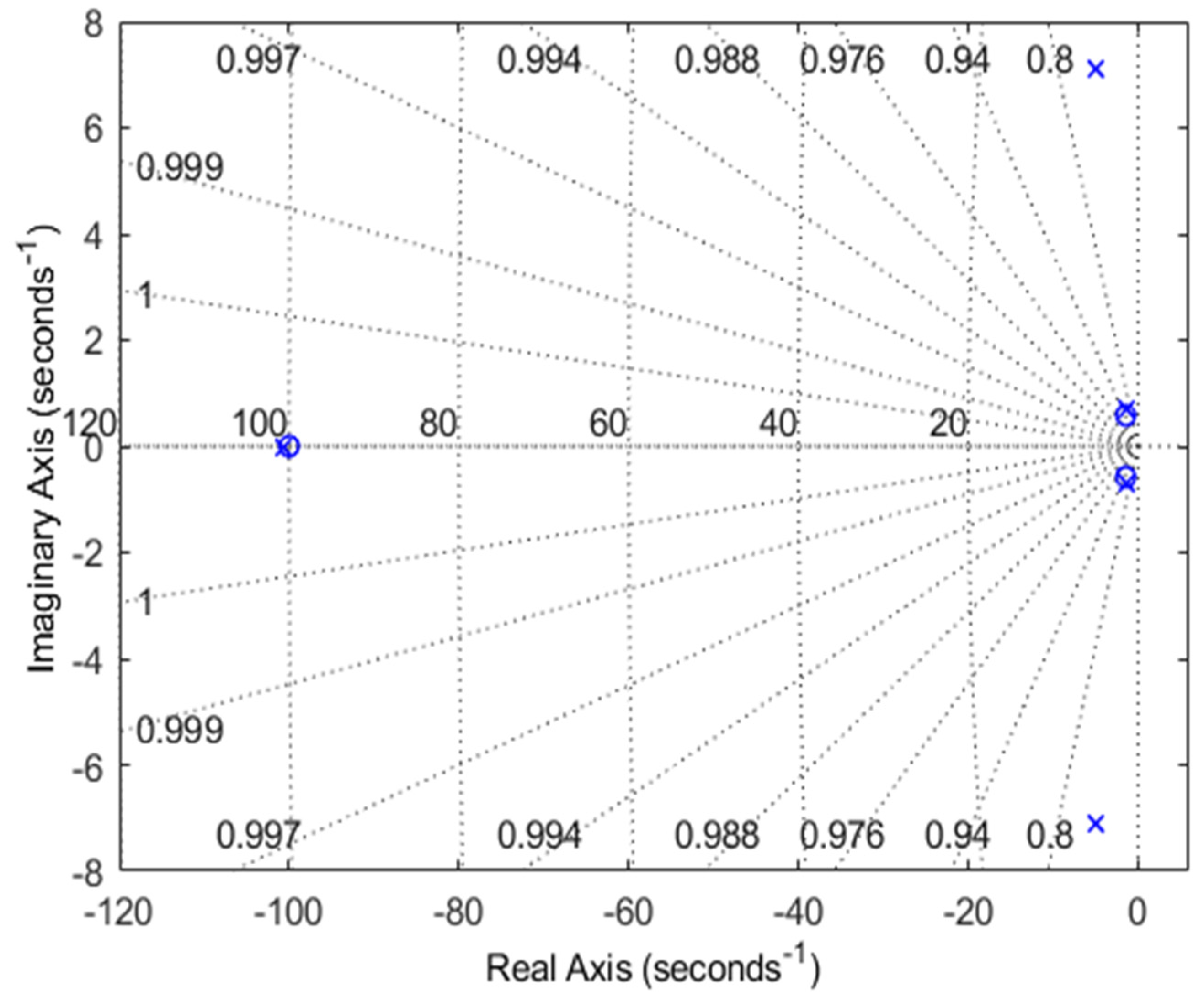
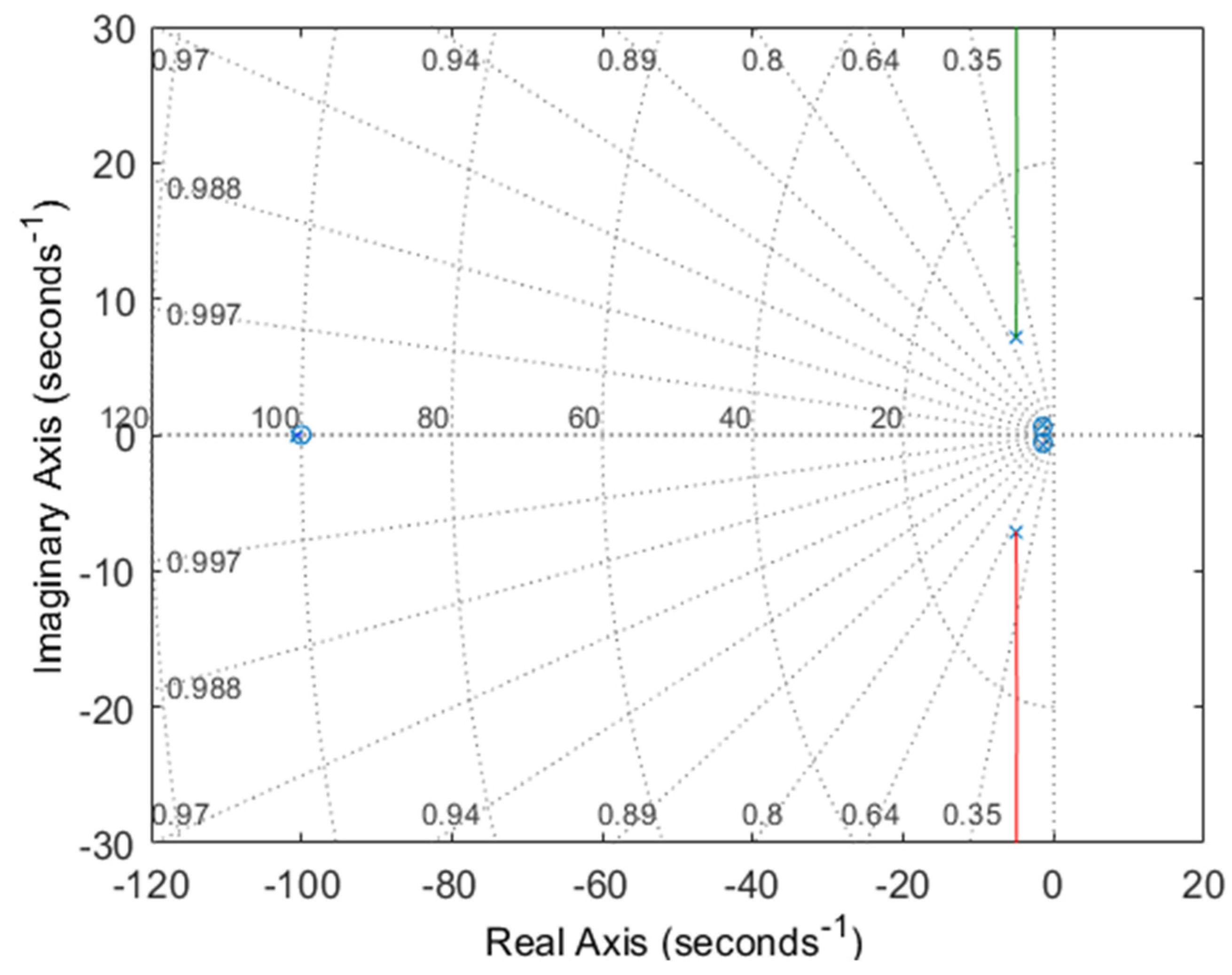
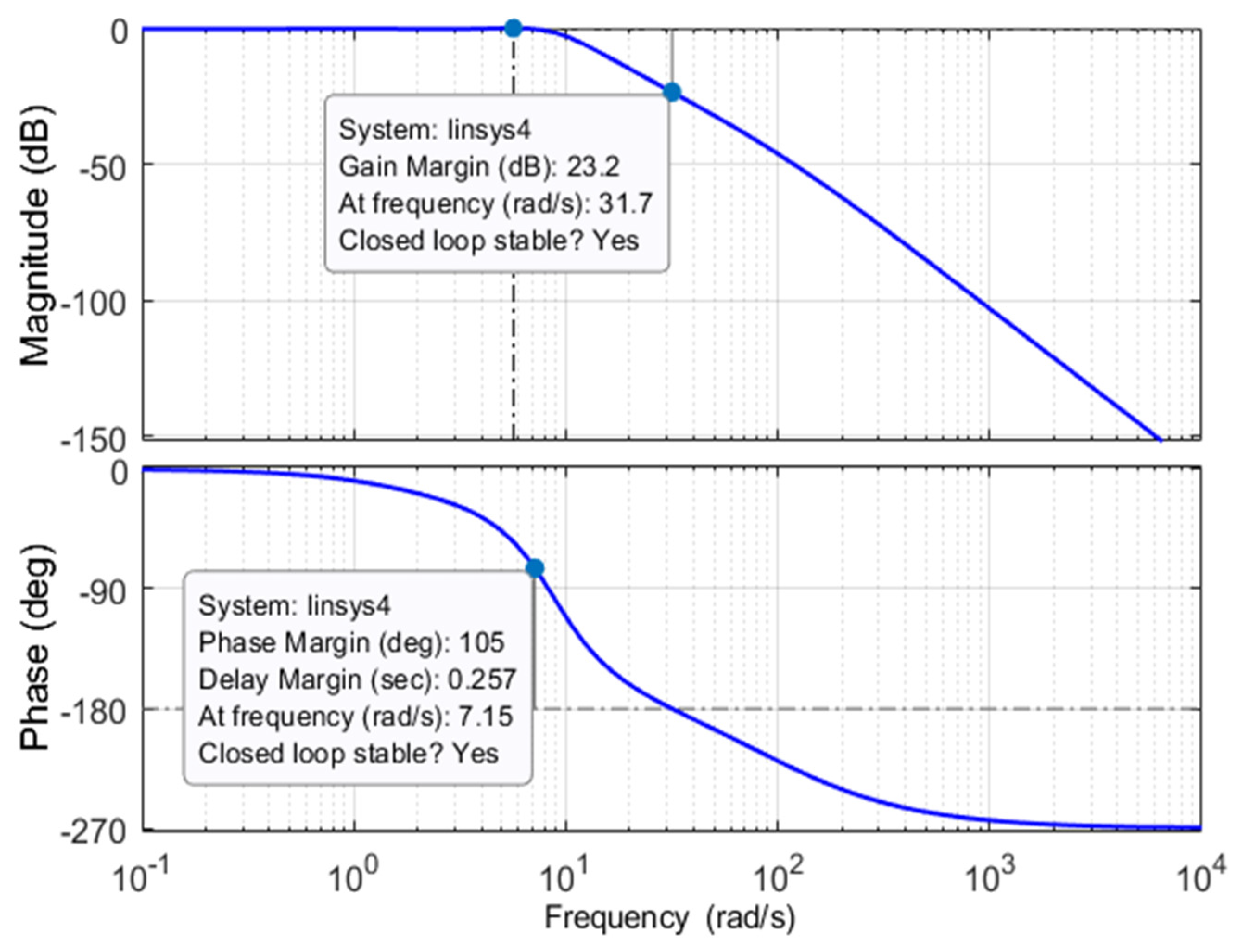
5.3. Stability Assessment

To evaluate the stability of the presented IWOA-based AVR design, the three most significant stability gauging criteria, i.e., pole-zero map, root-locus plot, and bode analyses were made and are depicted in Figure 8, Figure 9 and Figure 10, respectively.
It can be observed from Figure 9 and Figure 10 that the location of the closed-loop poles of the IWOA-based AVR system are s1 = −100.77, s2 = −5.02 + 7.09i, s3 = −5.02 − 7.09i, s4 = −1.35 + 0.68i and s5 = −1.35 − 0.68i, while the equivalent damping ratios are 1.00, 0.578, 0.578, 0.893 and 0.893, respectively. Since all of the closed-loop poles lie on the left half of the s-plane, the system is stable and possesses a suitable frequency response. The comparative simulation analysis of the various AI technique-based AVR systems for the closed-loop poles and damping ratios is presented in Table 3.

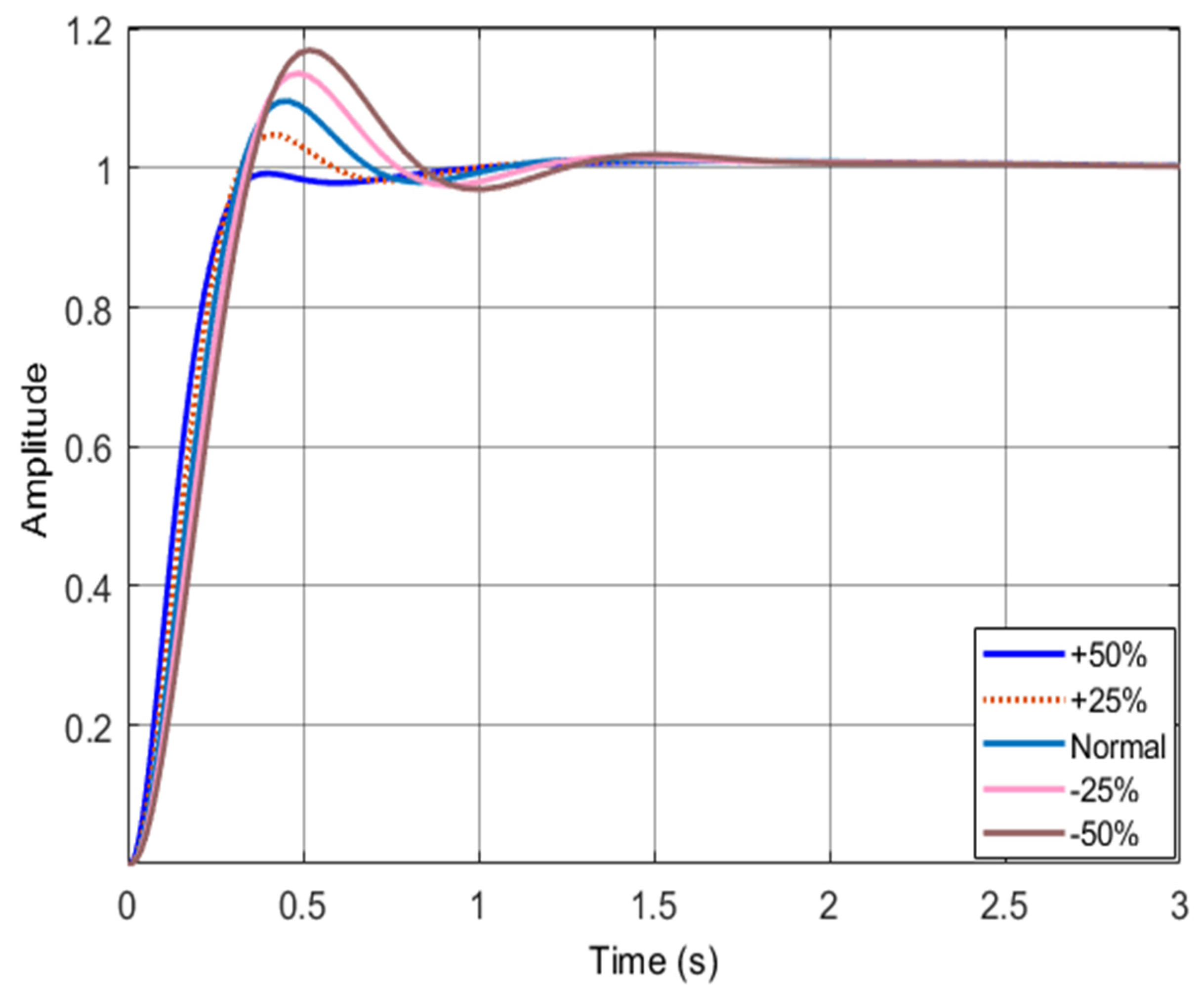
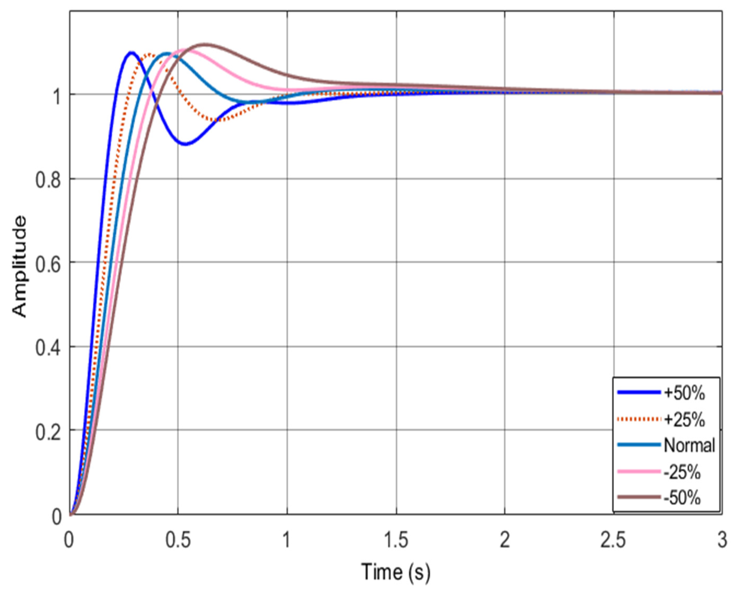
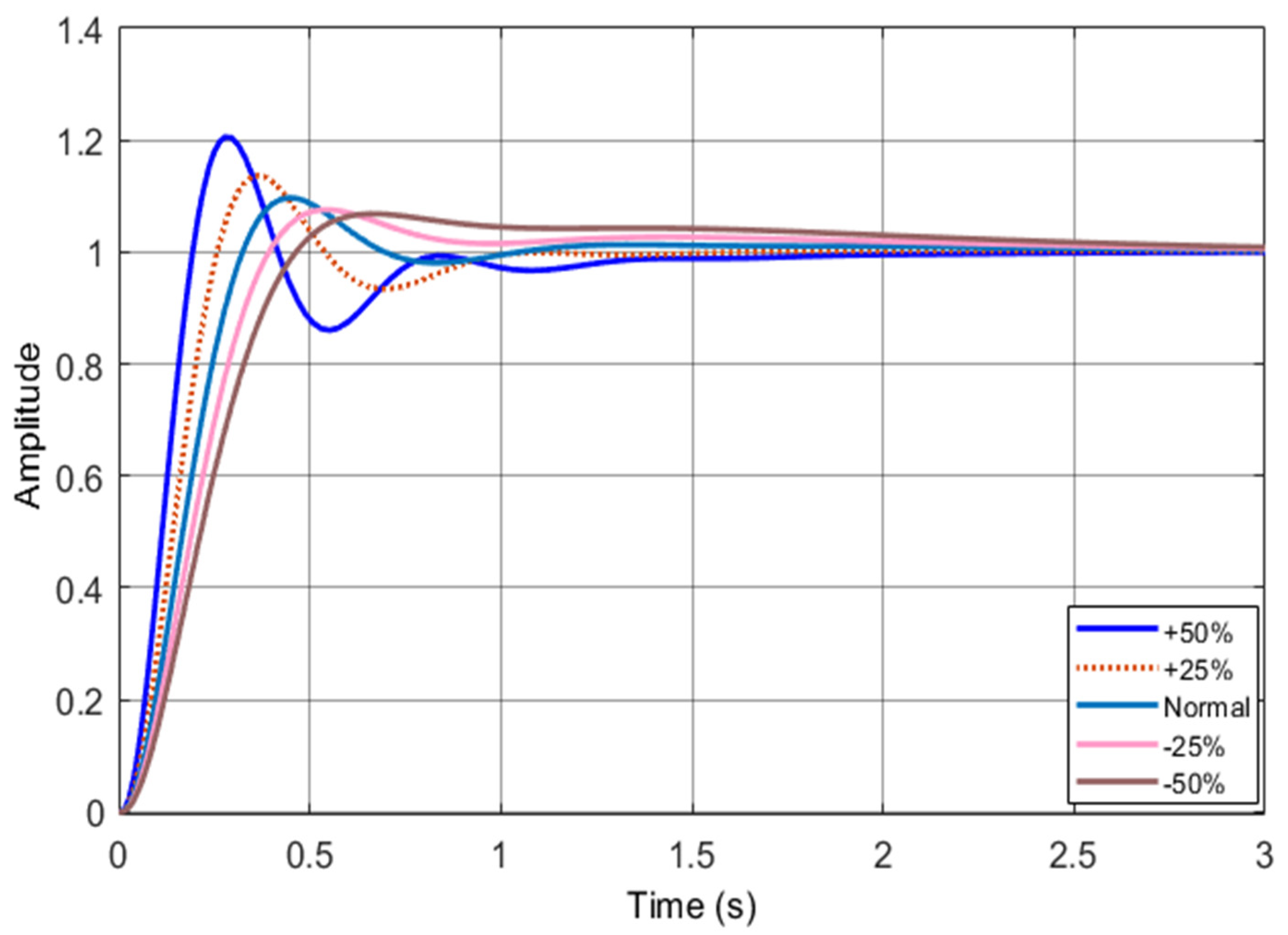
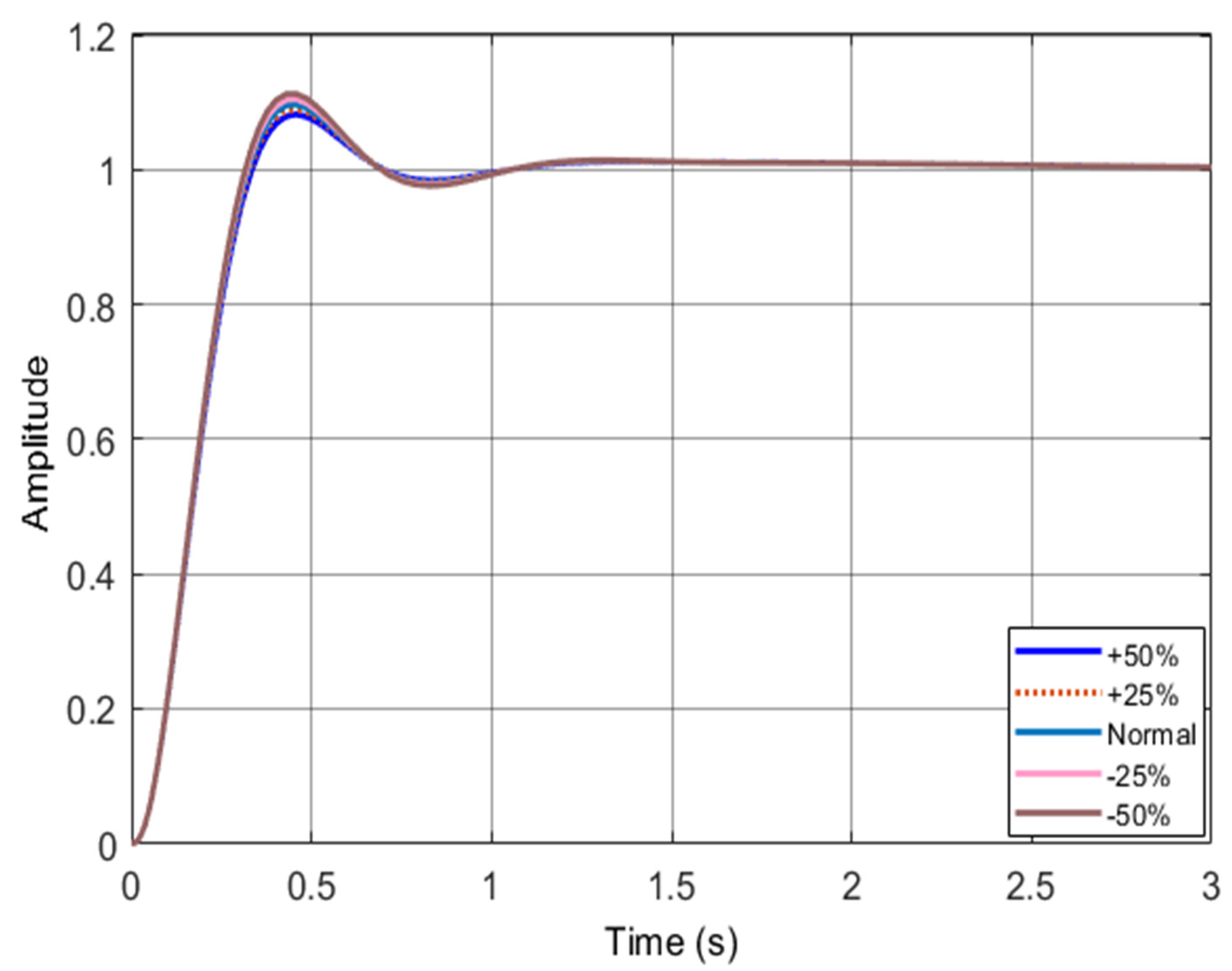
5.4. Robustness Analysis

This section carries out the robustness analysis of the proposed IWOA-based AVR system. Robustness is defined as the ability of a system to endure certain changes in the system parameters without affecting stability. In this research work, the system response is analyzed under the uncertainties in time constants for the amplifier, exciter, generator, and sensor from −50% to +50% with a step size of 25%. The outcomes of the robustness analysis are provided in Figure 11, Figure 12, Figure 13 and Figure 14.
It is obvious from Figure 11, Figure 12, Figure 13 and Figure 14 that the designed IWO-AVR system withstands the parameter variations and hence assures its stable operation during such parameter changes. Therefore, the robustness of the proposed IWOA-based AVR system is duly validated.

6. Conclusions

In this study, an improved version of WOA is proposed for the optimization of the PID gains in an AVR system in order to enhance its stability, robustness, and transient response simultaneously. Owing to the superior optimization capabilities, convergence profile, and self-adaptive behavior of the IWOA over its original counterpart, its intelligence was utilized to achieve the optimal values of the PID gains through minimization of an error-integrating FF. To authenticate the efficacy of the presented IWOA-based AVR, its corresponding dynamic response was compared against eight different studies conducted recently in the studied research field. The proposed algorithm-based PID tuning provides 6.30941%, 70.9013%, 68.2005%, 61.7709%, 38.3969%, 53.4354%, and 43.2469% less overshoot than that of WOA, DE, PSO, ABC, BBO, GOA, and PSA, respectively. From the simulation outcomes, the IWOA-based AVR design offers a better transient response as compared to the above-mentioned optimization algorithm-based AVRs. The results of this study prove that the proposed IWOA-PID controller offers appropriate stability and robustness since it sustained the variations in the system parameters without any significant change in its operational characteristics. One of the alternate options that needs to be considered for the optimal AVR design is the usage of a fractional order PID (FOPID) controller instead of PID. FOPID offers finer tuning compared to its conventional counterpart. However, it has two additional tuning gains, which would increase the optimization complexity and time.

Author Contributions

All authors planned the study and contributed to the idea and field of information. All authors have read and agreed to the published version of the manuscript.

Funding

This work is supported by the National Natural Science Foundation of China (NSFC) Grant 52150410399.

Conflicts of Interest

The authors declare no conflict of interest.

References

  1. Larik, R.; Mustafa, M.W.; Aman, M.; Jumani, T.; Sajid, S.; Panjwani, M. An Improved Algorithm for Optimal Load Shedding in Power Systems. Energies 2018, 11, 1808. [Google Scholar] [CrossRef] [Green Version]
  2. Saeed, M.S.; Mustafa, M.W.; Sheikh, U.U.; Jumani, T.A.; Mirjat, N.H. Ensemble Bagged Tree Based Classification for Reducing Non-Technical Losses in Multan Electric Power Company of Pakistan. Electronics 2019, 8, 860. [Google Scholar] [CrossRef] [Green Version]
  3. Altbawi, S.M.A.; Mokhtar, A.S.B.; Jumani, T.A.; Khan, I.; Hamadneh, N.N.; Khan, A. Optimal Design of Fractional Order PID Controller Based Automatic Voltage Regulator System Using Gradient-Based Optimization Algorithm. J. King Saud Univ.-Eng. Sci. 2021, 34. [Google Scholar] [CrossRef]
  4. Ngaleu, G.M.; Tamtsia, A.Y.; Kom, C.H. Design and Robust Analysis of Internal Model Controllers for an Automatic Voltage Regulation System. Int. Rev. Electr. Eng. 2020, 15, 474. [Google Scholar] [CrossRef]
  5. Jumani, T.; Mustafa, M.; Rasid, M.; Mirjat, N.; Baloch, M.; Salisu, S. Optimal Power Flow Controller for Grid-Connected Microgrids Using Grasshopper Optimization Algorithm. Electronics 2019, 8, 111. [Google Scholar] [CrossRef] [Green Version]
  6. Jumani, T.A.; Mustafa, M.W.; Rasid, M.M.; Mirjat, N.H.; Leghari, Z.H.; Saeed, M.S. Optimal Voltage and Frequency Control of an Islanded Microgrid Using Grasshopper Optimization Algorithm. Energies 2018, 11, 3191. [Google Scholar] [CrossRef] [Green Version]
  7. Laghari, J.A.; Mokhlis, H.; Abu Bakar, A.H.; Mohamad, H. A Fuzzy Based Load Frequency Control for Distribution Network Connected with Mini Hydro Power Plant. J. Intell. Fuzzy Syst. 2014, 26, 1301–1310. [Google Scholar] [CrossRef]
  8. Jumani, T.A.; Mustafa, M.W.; Hamadneh, N.N.; Atawneh, S.H.; Rasid, M.M.; Mirjat, N.H.; Bhayo, M.A.; Khan, I. Computational Intelligence-Based Optimization Methods for Power Quality and Dynamic Response Enhancement of Ac Microgrids. Energies 2020, 13, 4063. [Google Scholar] [CrossRef]
  9. Sahib, M.A. A Novel Optimal PID plus Second Order Derivative Controller for AVR System. Eng. Sci. Technol. Int. J. 2015, 18, 194–206. [Google Scholar] [CrossRef] [Green Version]
  10. Joseph, S.B.; Dada, E.G.; Abidemi, A.; Oyewola, D.O.; Khammas, B.M. Metaheuristic Algorithms for PID Controller Parameters Tuning: Review, Approaches and Open Problems. Heliyon 2022, 8, e09399. [Google Scholar] [CrossRef]
  11. Dogruer, T.; Can, M.S. Design and Robustness Analysis of Fuzzy PID Controller for Automatic Voltage Regulator System Using Genetic Algorithm. Trans. Inst. Meas. Control 2022, 44, 1862–1873. [Google Scholar] [CrossRef]
  12. Wu, Z.; Zhuang, Y.; Zhou, S.; Xu, S.; Yu, P.; Du, J.; Luo, X.; Abbas, G. Bi-Level Planning of Multi-Functional Vehicle Charging Stations Considering Land Use Types. Energies 2020, 13, 1283. [Google Scholar] [CrossRef] [Green Version]
  13. Jumani, T.A.; Mustafa, M.W.; Alghamdi, A.S.; Rasid, M.M.; Alamgir, A.; Awan, A.B. Swarm Intelligence-Based Optimization Techniques for Dynamic Response and Power Quality Enhancement of AC Microgrids: A Comprehensive Review. IEEE Access 2020, 8, 75986–76001. [Google Scholar] [CrossRef]
  14. Selvaraj, S.; Choi, E. Swarm Intelligence Algorithms in Text Document Clustering with Various Benchmarks. Sensors 2021, 21, 3196. [Google Scholar] [CrossRef]
  15. Zeybekoglu, U.; Ulke Keskin, A. Investigation of Applicability of Artificial Bee Colony Algorithm on Rainfall Intensity Duration Frequency Equations. J. Ecol. Eng. 2020, 21, 27–33. [Google Scholar] [CrossRef]
  16. Hekimoğlu, B. Sine-Cosine Algorithm-Based Optimization for Automatic Voltage Regulator System. Trans. Inst. Meas. Control 2019, 41, 1761–1771. [Google Scholar] [CrossRef]
  17. Hekimoglu, B.; Ekinci, S. Grasshopper Optimization Algorithm for Automatic Voltage Regulator System. In Proceedings of the 2018 5th International Conference on Electrical and Electronic Engineering (ICEEE), Istanbul, Turkey, 3–5 May 2018; IEEE: New York, NY, USA, 2018; pp. 152–156. [Google Scholar] [CrossRef]
  18. Kose, E. Optimal Control of AVR System with Tree Seed Algorithm-Based PID Controller. IEEE Access 2020, 8, 89457–89467. [Google Scholar] [CrossRef]
  19. Mosaad, A.M.; Attia, M.A.; Abdelaziz, A.Y. Whale Optimization Algorithm to Tune PID and PIDA Controllers on AVR System. Ain Shams Eng. J. 2019, 10, 755–767. [Google Scholar] [CrossRef]
  20. Xiong, G.; Zhang, J.; Shi, D.; He, Y. Parameter Extraction of Solar Photovoltaic Models Using an Improved Whale Optimization Algorithm. Energy Convers. Manag. 2018, 174, 388–405. [Google Scholar] [CrossRef]
  21. Kenney, R.D.; Winn, H.E.; Macaulay, M.C. Cetaceans in the Great South Channel, 1979–1989: Right Whale (Eubalaena glacialis). Cont. Shelf Res. 1995, 15, 385–414. [Google Scholar] [CrossRef]
  22. Goldbogen, J.A.; Friedlaender, A.S.; Calambokidis, J.; McKenna, M.F.; Simon, M.; Nowacek, D.P. Integrative Approaches to the Study of Baleen Whale Diving Behavior, Feeding Performance, and Foraging Ecology. Bioscience 2013, 63, 90–100. [Google Scholar] [CrossRef] [Green Version]
  23. Mirjalili, S.; Lewis, A. The Whale Optimization Algorithm. Adv. Eng. Softw. 2016, 95, 51–67. [Google Scholar] [CrossRef]
  24. Jumani, T.; Mustafa, M.; Rasid, M.M.; Anjum, W.; Ayub, S. Salp Swarm Optimization Algorithm-Based Controller for Dynamic Response and Power Quality Enhancement of an Islanded Microgrid. Processes 2019, 7, 840. [Google Scholar] [CrossRef] [Green Version]
  25. Memon, A.; Mustafa, M.W.B.; Jumani, T.A.; Olatunji Obalowu, M.; Malik, N. Salp Swarm Algorithm–Based Optimal Vector Control Scheme for Dynamic Response Enhancement of Brushless Double-fed Induction Generator in a Wind Energy Conversion System. Int. Trans. Electr. Energy Syst. 2021, 31, e13157. [Google Scholar] [CrossRef]
  26. Seborg, D.; Mellichamp, T.F.E.D. Process Dynamics & Control, 2nd ed.; Wiley India Pvt. Limited: New Delhi, India, 2006. [Google Scholar]
  27. Memon, A.; Wazir Bin Mustafa, M.; Anjum, W.; Ahmed, A.; Ullah, S.; Altbawi, S.M.A.; Jumani, T.A.; Khan, I.; Hamadneh, N.N. Dynamic Response and Low Voltage Ride-through Enhancement of Brushless Double-Fed Induction Generator Using Salp Swarm Optimization Algorithm. PLoS ONE 2022, 17, e0265611. [Google Scholar] [CrossRef] [PubMed]
  28. Khan, I.A.; Alghamdi, A.S.; Jumani, T.A.; Alamgir, A.; Awan, A.B.; Khidrani, A. Salp Swarm Optimization Algorithm-Based Fractional Order PID Controller for Dynamic Response and Stability Enhancement of an Automatic Voltage Regulator System. Electronics 2019, 8, 1472. [Google Scholar] [CrossRef] [Green Version]
Figure 1. General structure of a simple VR system [3].
Energies 15 05037 g001
Figure 2. Block diagram of AVR.
Energies 15 05037 g002
Figure 3. Flowchart of proposed IWOA-based optimal AVR design.
Energies 15 05037 g003
Figure 4. Proposed IWOA-based optimal design of an AVR system.
Energies 15 05037 g004
Figure 5. Convergence curves for the proposed WOA and IWOA for PID tuning.
Energies 15 05037 g005
Figure 6. Step response of the IWOA-AVR system.
Energies 15 05037 g006
Figure 7. Comparative analysis of the proposed IWOA-based AVR design with other well-known techniques used in the recent literature. DE-PID [15], PSO-PID [9], ABC-PID [15], BBO-PID [16], GOA-PID [17], PSA-PID [18].
Energies 15 05037 g007
Figure 8. Pole-zero map.
Energies 15 05037 g008
Figure 9. Root locus plot.
Energies 15 05037 g009
Figure 10. Bode plot.
Energies 15 05037 g010
Figure 11. Effect of amplifier gain variation.
Energies 15 05037 g011
Figure 12. Effect of exciter gain variation.
Energies 15 05037 g012
Figure 13. Effect of generator gain variation.
Energies 15 05037 g013
Figure 14. Effect of sensor gain variation.
Energies 15 05037 g014
Table 1. Convergence Evaluation for WOA and IWOA.
Optimization
Method
Number of Iterations to Reach
the Final Solution
Minimized Fitness Function Value
WOA350.005428
IWOA230.004996
Table 2. Comparative analysis of the dynamic response.
AVR DesignsTransient Response Evaluation Metrics
Peak Value%Mptrtpts
IWOA-PID (proposed)1.10009.560.21200.43900.6420
WOA-PID 1.102010.20380.20700.43230.9226
DE-PID [15]1.328532.85370.15160.36552.6495
PSO-PID [9]1.188218.81830.14930.33720.8145
PSO-PID [15]1.300630.06340.16100.38243.3994
ABC-PID [15]1.250125.00710.15570.36763.0939
BBO-PID [16]1.155215.51870.14850.31651.4457
GOA-PID [17]1.205320.53060.13000.28620.9706
PSA-PID [18]1.168416.84490.14450.30600.8039
Table 3. Closed-loop poles and damping ratios of the AVR system.
PID Tuning MethodClosed-Loop PolesDamping Ratio
IWOA-PID
(proposed)
−100.771.00
−5.02 + 7.09i0.578
−5.02 − 7.09i0.578
−1.35 + 0.68i0.893
−1.35 − 0.68i0.983
WOA-PID −1.021.00
−2.081.00
−4.79 + j7.33i0.548
−4.79 − j7.330.548
−101.001.00
DE-PID [15]−100.911.00
3.02 + j8.190.34
−3.02 − j8.190.34
−6.291.00
−0.221.00
PSO-PID [9]−1.021.00
−1.021.00
−2.001.00
4.64 + j9.500.439
−4.64 + j9.500.439
PSO-PID [15]−0.211.00
−6.261.00
−3.09 + j7.800.37
−3.09 − j7.800.37
−101.001.00
ABC-PID [15]−100.981.00
3.75 + j8.400.40
−3.75 + j8.400.40
−4.741.00
−0.251.00
BBO-PID [16]−100.001.00
−4.80 + j10.20.427
−4.80 − j10.20.427
−2.11.00
−0.5851.00
GOA-PID [17]−1011.00
−1.18 + j1.060.74
−1.18 − j1.060.74
−4.83 + j10.90.40
−4.83 − j10.90.40
PSA-PID [18]−1.28 + j0.1460.9936
−1.28 − j0.1460.9936
−4.82 + j10.110.4301
−4.82 − j10.110.4301
−101.001.00
Publisher’s Note: MDPI stays neutral with regard to jurisdictional claims in published maps and institutional affiliations.

