Article

Techno-Economic Assessment of the Integration of Direct Air Capture and the Production of Solar Fuels

by
Enric Prats-Salvado
1,2,*,
Nathalie Monnerie
1 and
Christian Sattler
1,2
1
German Aerospace Center (DLR), Institute of Future Fuels, 51147 Cologne, Germany
2
Faculty of Mechanical Science and Engineering, Institute of Power Engineering, Solar Fuel Production, Technische Universität Dresden, 01062 Dresden, Germany
*
Author to whom correspondence should be addressed.
Energies 2022, 15(14), 5017; https://doi.org/10.3390/en15145017
Submission received: 9 June 2022 / Revised: 2 July 2022 / Accepted: 6 July 2022 / Published: 9 July 2022

Abstract

:
Non-abatable emissions are one of the decarbonization challenges that could be addressed with carbon-neutral fuels. One promising production pathway is the direct air capture (DAC) of carbon dioxide, followed by a solar thermochemical cycle and liquid fuel synthesis. In this study, we explore different combinations of these technologies to produce methanol from an economic perspective in order to determine the most efficient one. For this purpose, a model is built and simulated in Aspen Plus®, and a solar field is designed and sized with HFLCAL®. The inherent dynamics of solar irradiation were considered with the meteorological data from Meteonorm® at the chosen location (Riyadh, Saudi Arabia). Four different integration strategies are assessed by determining the minimum selling price of methanol for each technology combination. These values were compared against a baseline with no synergies between the DAC and the solar fuels production. The results show that the most economical methanol is produced with a central low-temperature DAC unit that consumes the low-quality waste heat of the downstream process. Additionally, it is determined with a sensitivity analysis that the optimal annual production of methanol is 11.8 kt/y for a solar field with a design thermal output of 280 MW.

1. Introduction

Climate change caused by anthropogenic emissions is considered to be one of the most challenging issues that humanity will face in the current century: according to the available literature, a global warming of 2.7 °C could be reached by 2100 if no measures are taken [1,2,3], and this warming would have significant impacts on the ecosystems in the short and long term [4,5,6,7]. This threat, combined with the predicted depletion of oil and natural gas reserves in the following 50 years, [8,9,10] and the increasing need of a more resilient energy supply chain [11,12], requires taking a technological leap towards renewable energies.
Many authors have outlined the key role of synthetic fuels in the energy transition. These fuels can become a valuable energy-carrier for storing energy surpluses and transporting them between regions [13,14,15]. In addition, synthetic fuels could solve the challenges of the industries with non-abatable emissions [16,17,18]. Solar energy is often deemed to be the most suitable source for fuel production, thanks to its massive availability and the maturity of the solar thermal and photovoltaic infrastructure [19,20].
Fuels produced with solar energy are commonly referred to as solar fuels. A well-known example of a solar fuel is hydrogen, which is expected to become a key enabler of the energy transition and its production and consumption are already escalating worldwide [21,22,23]. Nevertheless, the availability of efficient pathways to produce liquid solar fuels still remains of great importance and some of the intrinsic hydrogen disadvantages related to their storage, transportation and safety need to be addressed [24,25]. Since liquid solar fuels are essentially hydrocarbons, their production requires both water and carbon dioxide as raw materials. As mentioned above, the carbon-neutrality of these fuels is fundamental and, therefore, atmospheric CO2 is preferred over other options that would cause positive net emissions after the fuel consumption [26,27].
Both the capture of atmospheric carbon dioxide (hereinafter referred to as direct air capture or DAC) and the production of solar fuels are thermodynamically non-favorable and consequently, energy-intensive processes [28,29,30]. Nonetheless, at the current state-of-the-art of both technologies, efficiencies can still be significantly improved and, as a result, solar fuels produced by this pathway can also become economically attractive.
There are manifold possibilities to produce solar fuels: some rely on the conversion of electricity produced with photovoltaic panels (e.g., electrolysis), others combine this electricity with heat from solar thermal technologies (e.g., high temperature electrolysis and hybrid sulfur cycle) and some processes solely require heat for this purpose (e.g., thermochemical cycle and sulfur-iodine cycle). Additionally, other innovative technologies use the solar light to power photochemical reactions [31]. The present work focuses on the solar thermochemical cycle, which consists of a metal oxide that is reduced at a high temperature to create oxygen vacancies in its lattice. Subsequently, the metal oxide is re-oxidized by steam or carbon dioxide at a lower temperature, producing hydrogen or carbon monoxide, respectively. After this second step, the cycle starts over again without any loss of metal oxide. A prominent advantage of this technology is the possibility of directly producing synthesis gas (i.e., a mixture of carbon monoxide and hydrogen) [32,33,34,35], from which the obtention of liquid fuels is a well-established technology with decades of commercialization [24,36,37]. In this study methanol was selected as the final product, but it is also possible to synthesize other hydrocarbons such as DME or synthetic kerosene [36].
Similarly, there is a wide portfolio of negative emissions technologies [38,39,40], but only two are considered in this study: high- and low-temperature DAC (often referred to as HT-DAC and LT-DAC, respectively). The former uses a liquid solvent that reacts with the atmospheric CO2 and requires high temperatures for its regeneration, whereas the latter employs a solid sorbent that binds with carbon dioxide molecules and can be regenerated at low temperatures. The rationale behind choosing these two technologies was evaluating the most mature technologies that are not based on biomass processing, as the cultivation of bioenergy crops could be especially challenging in the areas with the highest solar irradiation [26,41]. The point source carbon capture is not considered, since the CO2 from most industries (e.g., cement production) cannot be considered as a negative emission [39].
The connection of the DAC with the liquid solar fuels production is the basis of this study, which can be understood as a continuation of a previous work published by the authors [42]. In the first article, different process and energy integrations were identified, grouped in five different scenarios and evaluated from a thermodynamic point of view. The results showed that the integration was beneficial in all five cases and two of them were highlighted as the most promising. The present study builds on these findings and assesses the different suggested synergies from an economic perspective, thus providing more realistic recommendations. The fact that the focus of this work is on the integration of the technologies, rather than on the technologies themselves, sets it apart from the available literature in this field. Therefore, this study aims to highlight the opportunities offered by a comprehensive process design, even at an early stage, and narrow the uncertainties towards the eventual deployment of the technology on a commercial scale.

2. Materials and Methods

Figure 1 illustrates the main differences between the scenarios and the baseline. The common aspects in all scenarios are shown in gray. As the reader will notice, the thermochemical cycle (TCC) is powered by high temperature heat collected by the concentrated solar power (CSP) unit to produce H2 and CO, which are the feedstocks for the methanol synthesis (MS). The waste heat from the thermochemical cycle is used for both vacuum and electricity production in the vacuum system (VS) and Rankine cycle (RC), respectively.
Hereupon the scenarios differ: in the baseline, the direct air capture is a fully independent unit powered by the grid. Scenarios A and B rely on high temperature direct air capture. The former is powered by a solar approach (sHT-DAC) and the latter by an oxyfuel mixture using the oxygen recovered from the thermochemical cycle. Similarly, scenarios C and D use the low temperature direct air capture technology. In scenario C, this unit is centralized and powered by waste heat from the vacuum system and the Rankine cycle. Oppositely, in scenario D, the carbon capture is decentralized and the CO2 is extracted from the heating, ventilation and air conditioning systems (HVAC) of skyscrapers located near the plant [43].
In order to guarantee a meaningful comparison between these synergies, scenario E, described in a previous publication by the authors, is discarded [42]. This decision is justified by the fact that the scale of this scenario was limited by the power output of the solar dishes, which is traditionally in the kW-range [19]. This size differs by several orders of magnitude from the other scenarios and, therefore, the assumptions upon which this study is based are not compatible with it. A possible solution could be installing an array of several hundred solar dishes, but since scenario E was also integrated with the HVAC system of a building, this approach is challenged by the land availability in an urban landscape.
To enable an accurate techno-economic assessment, the location of the system had to be specified, and for this purpose an extensive tract of land nearby Riyadh (Saudi Arabia) was chosen. Riyadh offers an interesting combination of remarkably high direct normal irradiation (DNI) and large buildings with powerful air conditioning systems.

2.1. Model Modifications

The models of the thermochemical cycle and the methanol synthesis are built in Aspen Plus® V10. Although these models are already available after the previous study [42], some modifications are introduced:
  • The reduction reactors are unified in a single reduction reactor;
  • A closed circuit of supercritical CO2 is introduced for the high temperature heat transfer units;
  • The pressure in the reduction reactor is increased from 0.5 to 1 mbar;
  • The liquid ring pump in the vacuum system is replaced by two stages of steam jets;
  • A heat pump is added to the vacuum system to allow steam condensation at temperatures below the ambient temperature;
  • The CO separation technology is changed from absorption to VPSA (Vacuum Pressure Swing Adsorption).
Modification 1 does not impact the thermodynamic analysis in the first paper, but it reduces the total number of units required and simplifies the solar field design. Modification 2 is introduced after consultations with a company specialized in heat transfer of solids at high temperature in order to improve the technical feasibility of the process. Modifications 3, 4 and 5 reduce the energy demand of the vacuum system to allow the operation with only the waste heat of the thermochemical cycle. This energy demand had previously increased when the higher environmental temperatures of Riyadh are considered in the vacuum system simulation. Finally, modification 6 addresses the concerns about the intermittent operation of the absorption.

2.2. Methods for Cost Estimation

The cost estimation of each unit is performed based on the literature as described in Table 1. All the available data are converted into USD2021 with the average exchange rate and the CEPCI index. The correlations include material and pressure factors, and if their upper limits are surpassed, an additional parallel unit is added. The “seven-tenths rule” estimates the cost of a plant from existing cost and size data (Equation (1)) [44]. The value of K depends on the equipment class, but since the rule is only applied to processes involving many different units (e.g., DAC), the recommended value of 0.68 is used.
cost 2 cost 1 = ( size 2 size 1 ) K

2.3. Sizing Constraints

The sizing of the individual sections of the plant is non-trivial, as it depends on the operational regime of the individual steps (intermittent or continuous). Additionally, the solar irradiation changes significantly daily and seasonally. As a consequence, an optimally sized thermochemical cycle may not always be able to process all the heat captured by the solar field. To determine the nominal capacity of each step that leads to the lowest production costs of methanol, the following boundary conditions are defined:
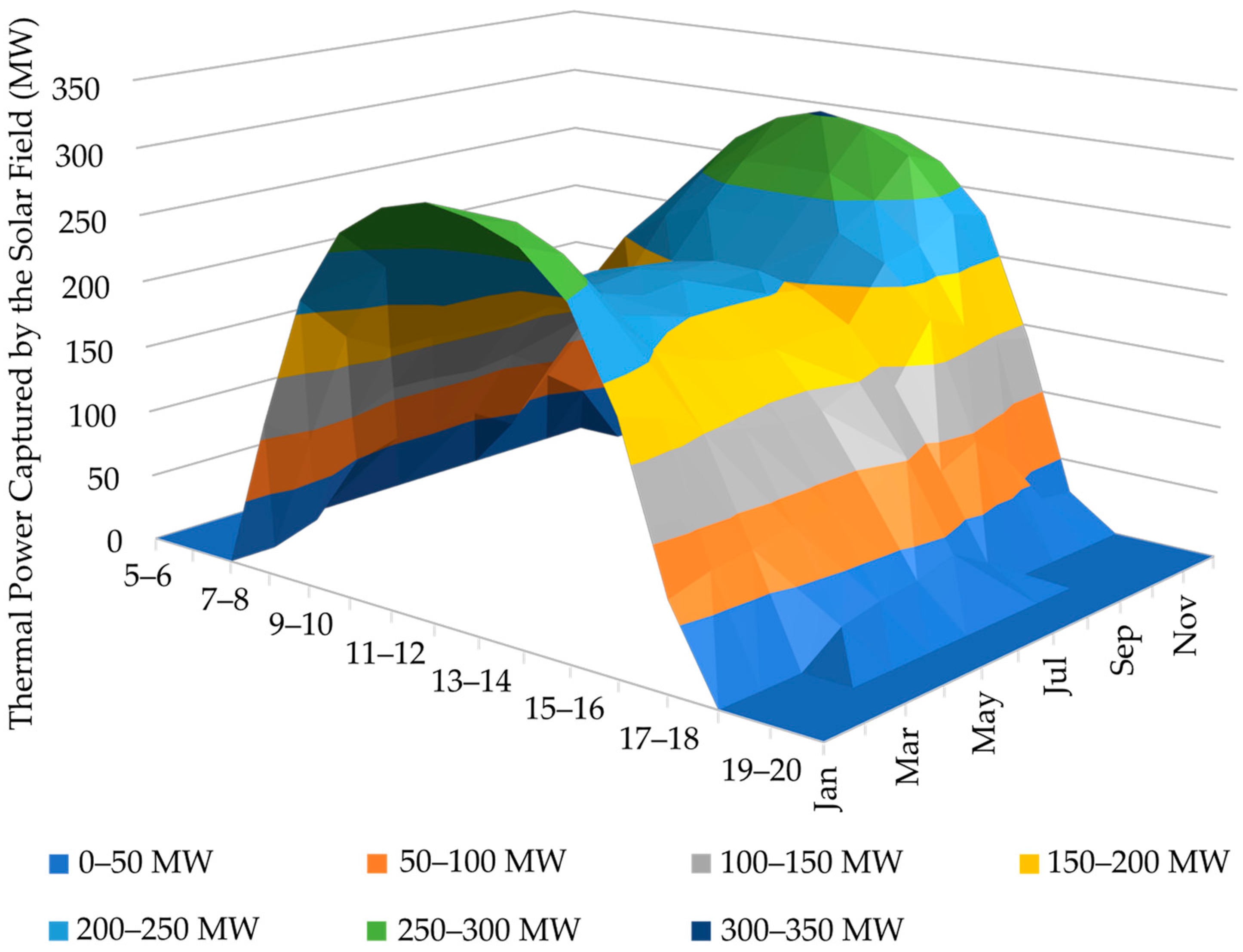
  • The solar field is designed to produce 280 MWth at noon on solar equinox;
  • Ten percent of the daily heat is lost to sensible heating of the plant;
  • If operated in continuous, the annual CO2 outputs of the DAC unit are oversized by 10%;
  • If operated intermittently, the nominal CO2 outputs of the DAC unit are oversized by 10%;
  • The intermediate storage of synthesis gas is set to 48 h;
  • When required, the intermediate storage of CO2 is set to 1 week;
  • The methanol plant is operated continuously and at a maximum of 90% of its capacity.
Condition 1 is calculated by adapting the circular solar field of the Cerro Dominador solar thermal plant to a cavity receiver (thus reducing the heliostat field to approximately one third) [53]. Condition 5 is determined after analyzing the solar irradiation in Riyadh (Saudi Arabia), where days without high direct normal irradiation are outliers throughout the year and, therefore, there is no need for a large intermediate storage.

2.4. Dynamics

The software HFLCAL® is used for the calculation of the optimal solar field shape and size [54]. Considering the location of the plant, the software also provides a matrix with the hourly field efficiency for the average day of each month of the year. A dataset of the direct normal irradiation in Riyadh during a year is obtained from the software Meteonorm® and is processed into a second matrix with the hourly irradiation for the average day of each month of the year. After combining the efficiency and the irradiation matrices with the optimal field size, the hourly capacity of the solar field over the year is plotted in Figure 2.
These data are combined with the results of the Aspen Plus® models to calculate the average daily production for each month of the year, as well as the annual output of the plant. Similarly, the heat and electricity flows between the units are also calculated at each hour of the day. The software HFLCAL® is also used to determine the size of the solar field required for the HT-DAC in Scenario A, which is a unique feature of this scenario.

2.5. Economic Evaluation

The minimum selling price of methanol is the criterion used to compare the scenarios with each other. Since it determines the revenue of the plant, it is calculated by forcing the net present value (NPV) of the investment in Equation (2) to 0 with an interest rate (r) of 10% [55]. As shown in Equation (3) [55], the following factors are considered in the calculation of the annual cash flow (CF): capital investment (CI), working capital (WC), revenue (R), expenditures (E) and an income tax (T) of 20%. The assets depreciation (D) is linearly calculated for 20 years and the lifetime of the plant is set to 25 years without salvage value. The capital investment is split equally between years 1 and 2, during which no production is expected due to the construction and commissioning of the plant. The working capital is paid in year 2 and reimbursed in year 27.
NPV = CF i ( 1 + r ) i = 0
CF i = CI i + WC i + ( E i + R i D i ) ( 1 T ) + D i .
As shown in Table 1, correlations are used as an estimation method for some equipment categories. These correlations only provide the purchased cost (PC), which must be corrected before it is added to the costs obtained with the other methods. The capital investment (CI) is calculated with Equation (4) [45]. The first term of this equation represents the direct costs (installation, instrumentation, piping, electrical works, buildings and land) and the second term represents the indirect costs (engineering, construction, fees and contingencies). Finally, when calculating the plant CI, the working capital (WC) and the annual maintenance expenses are estimated as 10% and 2% of it, respectively [45].
CI = 1.474 PC + 0.281 PC .
The plant revenue is mostly dominated by the methanol sales, but it also considers marketable by-products obtained in some scenarios, namely pure oxygen and electricity. The operational expenses include labor and maintenance as well as purified water to produce hydrogen, desalinated water for mirrors and, if required in the respective scenario, grid electricity, natural gas and additional desalinated water for the HT-DAC. Due to the nature of the process, no significant contaminant streams are released during its operation and therefore no expenses are associated with their treatment. However, some purges are burnt in a gas flare and, potentially, air contactors may release small amounts of solvent and sorbents into the nearby environment. Although these pollutants are presumably not to have a meaningful impact on the techno-economic assessment, they should and will be considered in future work to assess the sustainability of the process. Further details on the calculation of the revenue and expenses can be found in the Supplementary Materials.

3. Results and Discussion

The first result obtained with the model is the size of the thermochemical cycle that minimizes the methanol selling price for the given 280 MW solar field. For this purpose, the price of methanol for all scenarios is equally set to an arbitrary cost of 5000 USD2021/t and the NPV is plotted against the design power input for the thermochemical cycle.
As can be seen in Figure 3, the net present value reaches a maximum value at 235 MW for all scenarios, which translates to an annual methanol production of 11.8 kt/y. Therefore, this value is considered as the optimal trade-off between the extra costs associated with the oversizing of the plant and the loss of annual capacity caused by an undersized design. The small steps observed in the curves are caused by the addition of units in parallel when the limits of the correlations used are reached.
After the definition of the system size, the energy and mass balances between the units are also determined. To illustrate these results, a Sankey diagram for the energy flow is drawn for each scenario. For simplicity, only scenario C is shown in the main text, but the other Sankey diagrams can be found in the Appendix A. As the reader will observe in Figure 4, the intermediate storage (represented by the block labelled “TANK”) is not in a steady state. The reason for this is that the methanol synthesis downstream is operated in a continuous regime and, therefore, there are variations in hold-up during normal operation. For scenario C, the process is energetically autonomous (with the possibility of selling a small surplus to the electricity grid). In the absence of irradiation, all units in this scenario are stopped except for the methanol synthesis.
The calculation of the capital and operational expenses for each scenario follow these results, which are shown in Figure 5. The capital expenses associated with the solar input and the chemical process dominate the final price and are almost constant for all scenarios. Thus, scenario C leads as the most economical investment thanks to its cost-effective DAC technology. This scenario also shows the cheapest operational expense because of the savings in energy and process water, and the advantage of a lower maintenance expense as a consequence of a more economical capital investment. It is worth to mention that scenarios A, C and D are energetically autonomous and, therefore, do not require utilities. As the reader will notice, the HT-DAC based scenarios (i.e., baseline, A and B) require a higher input of process water due to the significant evaporation under the harsh conditions in the sunbelt.
Figure 6 provides a closer look into the composition of the capital expenses of the solar input and the chemical process. While the former is dominated by the heliostat fields, the latter is mainly determined by a combination of the power block, the heat exchangers and the intermediate storage of synthesis gas. These results are in line with other techno-economic assessments as they show that the solar field is the largest contributor to the total capital investment [52,56,57].
Figure 7 allows a better understanding of the cost reduction in the DAC units that can be achieved with the suggested synergies. In the HT-DAC, significant savings are expected for scenarios A and B due to the elimination of the CO2 compression and the air separation unit. Scenario A uses the sHT-DAC approach, where the natural gas combustion is replaced by a solar calciner. Although this change slightly increases the cost of the air contactor and adds an additional small solar field, this scenario is the most cost-effective HT-DAC approach. However, the lowest cost for the DAC equipment is in scenario C, which relies on a central LT-DAC that consumes very low-quality heat from the chemical plant. Although the same technology is used, scenario D is penalized by the compression and distribution of CO2 from two large buildings in Riyadh. The fact that two smaller LT-DAC units are required also increases the investment for this scenario.
Finally, the minimum selling price of methanol for each scenario is shown in Figure 8. It is safe to state that the strategies deployed in scenario C lead to the most cost-effective process. The individual contribution of the different factors can also be observed in Figure 8. Not surprisingly, the low cost of this scenario is directly connected to the low share of capital expenses for the direct air capture unit. Comparing this result with other available techno-economic assessments, it can be seen that the minimum selling price in the present work is similar to the value reported in another recent work [52], but significantly higher than in other studies [56,57,58]. However, the proportional contributions of the chemical and solar sections are in a similar range. Therefore, the difference can be attributed to the choice of more conservative assumptions in the present study. Moreover, in the above works, CO2 is considered as a raw material (thus included in the OPEX) and it is purchased at a relatively low price under the assumption that the costs of DAC would be reduced in the short and medium term. While this difference does not have a major impact, it also contributes to a decrease in the minimum selling price of methanol in the other studies.
It must also be mentioned that the obtained result is highly sensitive to parameters such as the cost, the lifetime or the CO2 capacity of the solid sorbent used in the LT-DAC. Due to the novelty of this technology, it is still not possible to guarantee the stability of the sorbents under extreme conditions (e.g., harsh temperatures). Regarding the HT-DAC, the most economical option is scenario A. Thanks to the higher technological maturity of the HT-DAC, the cost estimation of this scenario may be subjected to fewer uncertainties. Therefore, it is also worth considering this approach in future works and further investigating its challenges, such as the significant evaporative water losses in arid regions or the performance of the solar calciner.

4. Conclusions

Following the authors’ previous work in the field, scenarios A, B, C and D are analyzed with a techno-economic assessment and arecompared to a baseline. The results show that the technologies and integrations applied in scenario C lead to the most economical methanol. This result is justified by the fact that this scenario has both the lowest capital and operational expenses. The capital expenses are comparatively lower thanks to the cheapest DAC technology (LT-DAC) and the avoidance of the CO2 distribution and storage, which penalize scenario D. Concerning the operational expenses, scenario C, alongside with scenarios A and D, benefits from being energetically autonomous. Moreover, this is the scenario that requires the lowest water input thanks to the unavoidable moisture capture in the LT-DAC.
To achieve a lower production costs of methanol, the capital expenses of the thermochemical cycle must be reduced. Some of the critical parameters that could reduce them are, on the one hand, the improvement of metal oxides to achieve higher reduction extends and, on the other hand, the development of more efficient vacuum production systems. The conversion of the solar energy that cannot be processed by the thermochemical cycle (i.e., when the thermal output of the solar field surpasses the nominal capacity of the cycle) could also contribute to a lower methanol minimum selling price, even if this is only marginal.
To complete the current study, further work will focus on conducting a life-cycle assessment of the methanol produced in each scenario to ensure that the above recommendations do not compromise the carbon-neutrality of the fuel.

Supplementary Materials

The following supporting information can be downloaded at: https://www.mdpi.com/article/10.3390/en15145017/s1, Table S1: Cost data used to determine the operational expenses, Figure S1: Flowsheet of the Aspen Plus® simulation of synthetic fuel production, Table S2: Stream information of the Aspen Plus® simulation of synthetic fuel production, Figure S2: Flowsheet of the Aspen Plus® simulation of the vacuum system, Table S3: Stream information of the Aspen Plus® simulation of the steam Rankine cycle. Reference [59] is cited in the supplementary materials.

Author Contributions

Conceptualization, E.P.-S. and N.M.; funding acquisition, C.S.; investigation, E.P.-S.; project administration, N.M.; software, E.P.-S.; supervision, N.M.; writing—original draft, E.P.-S.; writing—review and editing, E.P.-S. and N.M. All authors have read and agreed to the published version of the manuscript.

Funding

This research was funded by the German Helmholtz Gemeinschaft research centers (HGF) Klimainitiative (HI-CAM: Helmholtz-Initiative Climate Adaptation and Mitigation).

Institutional Review Board Statement

Not applicable.

Informed Consent Statement

Not applicable.

Data Availability Statement

Not applicable.

Conflicts of Interest

The authors declare no conflict of interest.

Appendix A

Figure A1. Sankey diagram for the energy flow in scenario A. In the legend, the terms “HT”, “MT” and “LT” stand for high, medium and low temperature, respectively. Without solar irradiation, all the equipment is shut down except for the methanol synthesis (MS) and the fans of the HT-DAC, which are powered with a small Rankine cycle that consumes the waste heat of the methanol synthesis.
Energies 15 05017 g0a1
Figure A2. Sankey diagram for the energy flow in scenario B. In the legend, the terms “HT”, “MT” and “LT” stand for high, medium and low temperature, respectively. Without solar irradiation, all the equipment is shut down except for the methanol synthesis (MS) and the HT-DAC. The heat for the HT-DAC is provided by natural gas and the electricity is supplied by a small Rankine cycle that consumes the waste heat of the methanol synthesis.
Energies 15 05017 g0a2
Figure A3. Sankey diagram for the energy flow in scenario D. In the legend, the terms “HT”, “MT” and “LT” stand for high, medium and low temperature, respectively. Without solar irradiation, all the equipment is shut down except for the methanol synthesis (MS). All the electricity output of the plant is supplied to the buildings from which the CO2 is obtained to compensate additional energy expenses of the HVAC system.
Energies 15 05017 g0a3

References

  1. The Emissions Gap Report 2020; United Nations Environment Programme: Nairobi, Kenya, 2020; ISBN 978-92-807-3812-4.
  2. United Nations Environment Programme. Emissions Gap Report 2021: The Heat Is On—A World of Climate Promises Not Yet Delivered; United Nations Environment Programme: Nairobi, Kenya, 2021. [Google Scholar]
  3. Blunden, J.; Arndt, D.S. State of the Climate in 2019. Bull. Am. Meteorol. Soc. 2020, 101, S1–S429. [Google Scholar] [CrossRef]
  4. Aresta, M. Carbon Dioxide as Chemical Feedstock; Wiley-VCH: Weinheim, Germany, 2010; ISBN 9783527324750. [Google Scholar]
  5. Lenton, T.M.; Held, H.; Kriegler, E.; Hall, J.W.; Lucht, W.; Rahmstorf, S.; Schellnhuber, H.J. Tipping elements in the Earth’s climate system. Proc. Natl. Acad. Sci. USA 2008, 105, 1786–1793. [Google Scholar] [CrossRef] [PubMed] [Green Version]
  6. IPCC. Climate Change and Land: An IPCC Special Report on Climate Change, Desertification, Land Degradation, Sustainable Land Management, Food Security, and Greenhouse Gas Fluxes in Terrestrial Ecosystems; Intergovernmental Panel on Climate Change (IPCC): Geneva, Switzerland, 2019. [Google Scholar]
  7. IPCC. IPCC Special Report on the Ocean and Cryosphere in a Changing Climate; Cambridge University Press: Cambridge, UK, 2019; ISBN 9781009157964. [Google Scholar]
  8. SEI; IISD; ODI; E3G; UNEP. The Production Gap 2021 Report; Stockholm Environment Institute: Stockholm, Sweden, 2021. [Google Scholar]
  9. Bp. Full Report—Statistical Review of World Energy; BP: London, UK, 2021. [Google Scholar]
  10. U.S. Energy Information Administration. Proved Reserves of Crude Oil and Natural Gas in the United States, Year-End 2020; U.S. Department of Energy: Washington, DC, USA, 2022.
  11. IEA—International Energy Agency. Global Gas Security Review 2019; OECD: Paris, France, 2019; ISBN 9789264911765. [Google Scholar]
  12. IEA—International Energy Agency. Security of Clean Energy Transitions; OECD: Paris, France, 2021; ISBN 9789264903395. [Google Scholar]
  13. Wan, C.; Zhou, L.; Xu, S.; Jin, B.; Ge, X.; Qian, X.; Xu, L.; Chen, F.; Zhan, X.; Yang, Y.; et al. Defect engineered mesoporous graphitic carbon nitride modified with AgPd nanoparticles for enhanced photocatalytic hydrogen evolution from formic acid. Chem. Eng. J. 2022, 429, 132388. [Google Scholar] [CrossRef]
  14. Mengis, N.; Kalhori, A.; Simon, S.; Harpprecht, C.; Baetcke, L.; Prats-Salvado, E.; Schmidt-Hattenberger, C.; Stevenson, A.; Dold, C.; Zohbi, J.; et al. Net-Zero CO2 Germany—A Retrospect from the Year 2050. Earth’s Future 2022, 10. [Google Scholar] [CrossRef]
  15. Liebich, A.; Fröhlich, T.; Münter, D.; Fehrenbach, H.; Simon, S.; Maier, S.; Albrecht, F.; Pregger, T.; Schillings, C.; Moser, M.; et al. System Comparison of Storable Energy Carriers from Renewable Energies; Umweltbundesamt: Dessau-Roßlau, Germany, 2021. [Google Scholar]
  16. Stechel, E.B.; Miller, J.E. Re-energizing CO2 to fuels with the sun: Issues of efficiency, scale, and economics. J. CO2 Util. 2013, 1, 28–36. [Google Scholar] [CrossRef]
  17. Fasihi, M.; Bogdanov, D.; Breyer, C. Long-Term Hydrocarbon Trade Options for the Maghreb Region and Europe—Renewable Energy Based Synthetic Fuels for a Net Zero Emissions World. Sustainability 2017, 9, 306. [Google Scholar] [CrossRef] [Green Version]
  18. Ram, M.; Galimova, T.; Bogdanov, D.; Fasihi, M.; Gulagi, A.; Breyer, C.; Micheli, M.; Crone, K. Powerfuels in a Renewable Energy World—Global Volumes, Costs, and Trading 2030 to 2050; Lappeenranta: Berlin, Germany, 2020. [Google Scholar]
  19. World Bank. Concentrating Solar Power: Clean Power on Demand 24/7; World Bank: Washington, DC, USA, 2020. [Google Scholar]
  20. IRENA. Renewable Power Generation Costs in 2020; International Renewable Energy Agency: Abu Dhabi, United Arab Emirates, 2021; ISBN 9789292603489. [Google Scholar]
  21. Agora Energiewende and AFRY Management Consulting. No-Regret Hydrogen: Charting Early Steps for H2 Infrastructure in Europe; Agora Energiewende: Berlin, Germany, 2021. [Google Scholar]
  22. Hinkley, J.T. A New Zealand Perspective on Hydrogen as an Export Commodity: Timing of Market Development and an Energy Assessment of Hydrogen Carriers. Energies 2021, 14, 4876. [Google Scholar] [CrossRef]
  23. Grube, T.; Reul, J.; Reuß, M.; Calnan, S.; Monnerie, N.; Schlatmann, R.; Sattler, C.; Robinius, M.; Stolten, D. A techno-economic perspective on solar-to-hydrogen concepts through 2025. Sustain. Energy Fuels 2020, 4, 5818–5834. [Google Scholar] [CrossRef]
  24. German Environment Agency. Power-to-Liquids: Potentials and Perspectives; Umweltbundesamt: Dessau-Roßlau, Germany, 2016. [Google Scholar]
  25. International Renewable Energy Agency (IRENA) and the Methanol Institute. Innovation Outlook: Renewable Methanol; International Renewable Energy Agency: Abu Dhabi, United Arab Emirates, 2021; ISBN 978-92-9260-320-5. [Google Scholar]
  26. Deutz, S.; Bardow, A. Life-cycle assessment of an industrial direct air capture process based on temperature–vacuum swing adsorption. Nat. Energy 2021, 6, 203–213. [Google Scholar] [CrossRef]
  27. Madhu, K.; Pauliuk, S.; Dhathri, S.; Creutzig, F. Understanding environmental trade-offs and resource demand of direct air capture technologies through comparative life-cycle assessment. Nat. Energy 2021, 6, 1035–1044. [Google Scholar] [CrossRef]
  28. Physics, A.P. Direct Air Capture of CO2 with Chemicals: A Technology Assessment for the APS Panel on Public Affairs; American Physical Society: College Park, MD, USA, 2011. [Google Scholar]
  29. Wilcox, J. Carbon Capture; Springer: New York, NY, USA, 2012; ISBN 978-1-4614-2214-3. [Google Scholar]
  30. Wilcox, J.; Psarras, P.C.; Liguori, S. Assessment of reasonable opportunities for direct air capture. Environ. Res. Lett. 2016, 12, 065001. [Google Scholar] [CrossRef] [Green Version]
  31. Blanco, M.; Ramirez Santigosa, L. Advances in Concentrating Solar Thermal Research and Technology; Woodhead Publishing: Oxford, UK, 2016; ISBN 9780081005163. [Google Scholar]
  32. Agrafiotis, C.; Roeb, M.; Sattler, C. 4.18 Solar Fuels. In Comprehensive Energy Systems; Dincer, I., Ed.; Elsevier: Amsterdam, The Netherlands, 2018; ISBN 978-0-12-814925-6. [Google Scholar]
  33. Bulfin, B.; Vieten, J.; Agrafiotis, C.; Roeb, M.; Sattler, C. Applications and Limitations of Two Step Metal Oxide Thermochemical Redox Cycles; A Review. J. Mater. Chem. 2017, 5, 18951–18966. [Google Scholar] [CrossRef]
  34. Lua, Y.; Zhua, L.; Agrafiotis, C.; Vieten, J.; Roeb, M.; Sattler, C. Solar fuels production: Two-step thermochemical cycles with cerium-based oxides. Progess Energy Combust. Sci. 2019, 75, 100785. [Google Scholar] [CrossRef]
  35. Marxer, D.; Furler, P.; Takacs, M.; Steinfeld, A. Solar thermochemical splitting of CO2 into separate streams of CO and O2 with high selectivity, stability, conversion, and efficiency. Energy Environ. Sci. 2017, 10, 1142–1149. [Google Scholar] [CrossRef] [Green Version]
  36. Moumin, G.; Neumann, N.C.; Roeb, M.; Rosenstiel, A.; Puga, E.V.; Dux, D.; Keuchel, B.; Walther, G.; Zeeb, P. CO2 Utilization in North Rhine-Westphalia: A Feasibility Study to Accelerate Implementation; German Aerospace Center (DLR): Cologne, Germany, 2021. [Google Scholar]
  37. Schäppi, R.; Rutz, D.; Dähler, F.; Muroyama, A.; Haueter, P.; Lilliestam, J.; Patt, A.; Furler, P.; Steinfeld, A. Drop-in fuels from sunlight and air. Nature 2022, 601, 63–68. [Google Scholar] [CrossRef]
  38. Committee on Developing a Research Agenda for Carbon Dioxide Removal and Reliable Sequestration; Board on Atmospheric Sciences and Climate; Board on Energy and Environmental Systems; Board on Agriculture and Natural Resources; Board on Earth Sciences and Resources; Board on Chemical Sciences and Technology; Ocean Studies Board; Division on Earth and Life Studies; National Academies of Sciences, Engineering, and Medicine. Negative Emissions Technologies and Reliable Sequestration: A Research Agenda; The National Academis Press: Washington, DC, USA, 2018; ISBN 9780309484527. [Google Scholar]
  39. Fasihi, M.; Efimova, O.; Breyer, C. Techno-economic assessment of CO2 direct air capture plants. J. Clean. Prod. 2019, 224, 957–980. [Google Scholar] [CrossRef]
  40. McQueen, N.; Gomes, K.V.; McCormick, C.; Blumanthal, K.; Pisciotta, M.; Wilcox, J. A review of direct air capture (DAC): Scaling up commercial technologies and innovating for the future. Prog. Energy 2021, 3, 32001. [Google Scholar] [CrossRef]
  41. Kaya, A.; Tok, M.; Koc, M. A Levelized Cost Analysis for Solar-Energy-Powered Sea Water Desalination in The Emirate of Abu Dhabi. Sustainability 2019, 11, 1691. [Google Scholar] [CrossRef] [Green Version]
  42. Prats-Salvado, E.; Monnerie, N.; Sattler, C. Synergies between Direct Air Capture Technologies and Solar Thermochemical Cycles in the Production of Methanol. Energies 2021, 14, 4818. [Google Scholar] [CrossRef]
  43. Dittmeyer, R.; Klumpp, M.; Kant, P.; Ozin, G. Crowd oil not crude oil. Nat. Commun. 2019, 10, 1–8. [Google Scholar] [CrossRef] [Green Version]
  44. Remer, D.S.; Chai, L.H. Process Equipment, Cost Scale-Up; Marcel Dekker, Inc.: New York, NY, USA, 1993; ISBN 9780824724511. [Google Scholar]
  45. Peters, M.S.; Timmerhaus, K.D.; West, R.E. Plant Design and Economics for Chemical Engineers, 5th ed.; Peters, M.S., Timmerhaus, K.D., West, R.E., Eds.; McGraw-Hill: New York, NY, USA, 2003; ISBN 9780072392661. [Google Scholar]
  46. Lim, Y.-I.; Choi, J.; Moon, H.-M.; Kim, G.-H. Techno-economic Comparison of Absorption and Adsorption Processes for Carbon Monoxide (CO) Separation from Linze-Donawitz Gas (LDG). Korean Chem. Eng. Res. 2015, 54, 320–331. [Google Scholar] [CrossRef] [Green Version]
  47. Cheang, V.T.; Hedderwick, R.A.; McGregor, C. Benchmarking supercritical carbon dioxide cycles against steam Rankine cycles for Concentrated Solar Power. Solar Energy 2015, 113, 199–211. [Google Scholar] [CrossRef]
  48. Marina, A.; Spoelstra, S.; Zondag, H.A.; Wemmers, A.K. An estimation of the European industrial heat pump market potential. Renew. Sustain. Energy Rev. 2021, 139, 110545. [Google Scholar] [CrossRef]
  49. Peletiri, S.P.; Rahmanian, N.; Mujtaba, I.M. CO2 Pipeline Design: A Review. Energies 2018, 11, 2184. [Google Scholar] [CrossRef] [Green Version]
  50. Keith, D.; Holmes, G.; St. Angelo, D.; Heidel, K. A Process for Capturing CO2 from the Atmosphere. Joule 2018, 2, 006. [Google Scholar] [CrossRef] [Green Version]
  51. National Academies of Sciences, Engineering, and Medicine. Negative Emissions Technologies and Reliable Sequestration: A Research Agenda; The National Academies Press: Washington, DC, USA, 2019. [Google Scholar] [CrossRef]
  52. Falter, C.; Valente, A.; Habersetzer, A.; Iribarren, D.; Dufour, J. An integrated techno-economic, environmental and social assessment of the solar thermochemical fuel pathway. Sustain. Energy Fuels 2020, 4, 3992–4002. [Google Scholar] [CrossRef]
  53. SolarPACES. Atacama I/Cerro Dominador 110 MW CSP + 100 MW PV CSP Project. Available online: https://solarpaces.nrel.gov/project/atacama-i-cerro-dominador-110mw-csp-100-mw-pv (accessed on 11 May 2021).
  54. Schwarzbözl, P.; Pitz-Paal, R.; Schmitz, M. Visual HFLCAL—A Software Tool for Layout and Optimisation of Heliostat Fields. In Proceedings of the 15th International SolarPACES Symposium, Berlin, Germany, 15–18 September 2009. [Google Scholar]
  55. Brealey, R.A.; Myers, S.C.; Allen, F. Principles of Corporate Finance, 10th ed.; McGraw-Hill/Irwin: New York, NY, USA, 2011. [Google Scholar]
  56. Monnerie, N.; Gan, P.G.; Roeb, M.; Sattler, C. Methanol production using hydrogen from concentrated solar energy. Hydrog. Energy Publ. 2020, 45, 26117–26125. [Google Scholar] [CrossRef]
  57. Kim, J.; Henao, C.A.; Johnson, T.A.; Dedrick, D.E.; Miller, J.E.; Stechel, E.B.; Maravelias, C.T. Methanol production from CO2 using solar-thermal energy: Process development and techno-economic analysis. Energy Environ. Sci. 2011, 4, 3122. [Google Scholar] [CrossRef]
  58. Kim, J.; Johnson, T.A.; Miller, J.E.; Stechel, E.B.; Maravelias, C.T. Fuel production from CO2 using solar-thermal energy: System level analysis. Energy Environ. Sci. 2012, 5, 8417–8429. [Google Scholar] [CrossRef]
  59. Falter, C.; Pitz-Paal, R. Water Footprint and Land Requirement of Solar Thermochemical Jet-Fuel Production. Environ. Sci. Technol. 2017, 51, 12938–12947. [Google Scholar] [CrossRef]
Figure 1. Simplified graphical overview of the different scenarios and the baseline. The abbreviations in the figure stand for: “HT-DAC” = high temperature direct air capture; “LT-DAC” = low temperature direct air capture; “HVAC” = heating, ventilation and air conditioning; “CSP” = concentrated solar power; “TCC” = thermochemical cycle; “MS” = methanol synthesis; “VS” = vacuum system and “RC” = Rankine cycle.
Energies 15 05017 g001
Figure 2. Hourly capacity of the solar field in Riyadh over the year based on real meteorological data of the location.
Energies 15 05017 g002
Figure 3. Sensitivity of the net present value (NPV) prior to the design power input for the thermochemical cycle. The selling price of methanol is equally set at 5000 USD2021/t for all scenarios.
Energies 15 05017 g003
Figure 4. Sankey diagram for the energy flow in scenario C. In the legend, the terms “HT”, “MT” and “LT” stand for high, medium and low temperature, respectively.
Energies 15 05017 g004
Figure 5. Overview of the capital expenses (left) and operational expenses (right) for each scenario.
Energies 15 05017 g005
Figure 6. Breakdown of the capital expenses included in the solar input category (left) and the chemical process category (right). The charts show the capital investment for each category in MUSD2021.
Energies 15 05017 g006
Figure 7. Breakdown of the capital expenses of the DAC technologies. The left plot compares the scenarios using HT-DAC and the right one, the scenarios relying on LT-DAC.
Energies 15 05017 g007
Figure 8. Minimum selling price per liter of methanol for each scenario (left) and individual contribution of each category for scenario C (right).
Energies 15 05017 g008
Table 1. Overview of methods used for the cost estimation of each equipment category. The term “HX” stands for heat exchanger.
Equipment ClassDesign ParameterEstimation MethodSource
CompressorsPowerCorrelation[45]
HX: Shell & TubeAreaCorrelation[45]
HX: Air-cooledAreaCorrelation[45]
HX: FurnacePowerCorrelation[45]
Reactors (non-solar)Area (heat exchange)Correlation[45]
Flash separatorsVolumeCorrelation[45]
VPSAVolumeCorrelation[45,46]
Storage tanksMetal massCorrelation[45]
Steam jetsGas flowrateCorrelation[45]
Power blocksEnergy inputSeven-tenths rule[47]
Heat pumpEnergy outputLinear[48]
CO2 PipelineLength & DiameterLinear[49]
HT-DAC 1Annual CO2 outputSeven-tenths rule[50]
LT-DAC 1Annual CO2 outputSeven-tenths rule[51]
Solar reactorsThermal power inputPower Law[52]
Heliostat fieldHeliostat areaLinear[52]
Solar towerThermal power inputLinear[52]
1 Additionally, some unit operations of the DAC system are removed, depending on each scenario.
Publisher’s Note: MDPI stays neutral with regard to jurisdictional claims in published maps and institutional affiliations.

