Article

New Cell Balancing Technique Using SIMO Two-Switch Flyback Converter with Multi Cells

Department of Electrical Engineering, Chonnam National University, Gwangju 61186, Korea
*
Author to whom correspondence should be addressed.
Energies 2022, 15(13), 4806; https://doi.org/10.3390/en15134806
Submission received: 13 June 2022 / Revised: 24 June 2022 / Accepted: 28 June 2022 / Published: 30 June 2022
(This article belongs to the Section D: Energy Storage and Application)

Abstract

:
Recently, as the perception of eco-friendliness has changed, the demand for energy storage devices has been rapidly increasing due to the growth of the electric vehicle industry and smart grid facilities, which are emerging as an alternative to next-generation electricity supply and demand. Therefore, the importance of battery management technology is growing, and various voltage balancing techniques between battery cells are being studied in order to maintain high efficiency and continuous performance of batteries. This paper proposes a voltage balancing topology using a single input-multiple output (SIMO) two-switch flyback converter in a series battery configuration to resolve voltage imbalance between batteries. The characteristic of the proposed topology is that each cell on the secondary side of the two-switch flyback converter is connected to one high-frequency transformer to share the magnetic flux, and voltage balancing is performed according to the switch operation of the converter. At this time, the accumulated excess energy of the converter is refluxed to the power supply side through the freewheeling diode and converted into reactive power. The verification of the usefulness of the theoretical analysis in this paper was based on the analysis of the dynamic characteristics and steady state of the circuit through PSIM and experiments, and was conducted for one module composed of four cells.

1. Introduction

A representative energy storage device currently receiving attention is an energy storage system (ESS) using a secondary battery [1,2]. ESS refers to a system that can store energy during periods of low power demand and stably provide energy when power demand is high [3,4]. To this end, it is essential to frequently check the condition of the battery through the establishment and monitoring of a stable current management system upon charging and discharging the battery. In a large-capacity ESS using a secondary battery, in order to reduce the current rating, a series configuration of battery cells and modules is essential. Although there is no problem in the initial stage of the cell composition or the force composition, the stability of the cell voltage decreases due to physical and chemical causes as the operating time passes [5,6]. Accordingly, a difference in the amounts of charge between batteries constituting a cell occurs and results in an imbalance between the count unit and the module unit [7,8,9]. For the long-term operation of a system that includes batteries with different voltage capacities in a module unit, overcharging of batteries during repeated charging and discharging accelerates aging and causes a reduction in overall system efficiency and performance [9,10,11]. Accordingly, for stable ESS operation and battery management, a voltage balancing operation that can synchronize battery charging and discharging is required [12,13,14].
Existing battery balancing techniques typically include a passive method and an active method shown in Figure 1. The passive balancing method is a parallel configuration of resistors for energy consumption in the battery cells [15,16]. The passive balancing principle is a method of controlling the imbalance of the entire cell voltage by dissipating energy in the resistor for a cell with a higher charge voltage based on the cell with the lowest charge voltage. While this method has the advantages of a simple structure and low cost, energy consumed in the balancing process cannot be reused; hence, it is not efficient from a system operation point of view due to power loss. Moreover, if there are cells whose charging capacity is lowered due to the presence of aging cells, there is also the disadvantage that the charging capacity of the entire ESS may be reduced [17,18].
The active balancing method performs cell balancing by moving charges from a battery cell with a high voltage capacity to a battery cell with a low voltage capacity and can solve the problem of the voltage capacity of the ESS compared with the passive balancing method [19,20].
In addition, as it is possible to selectively perform individual balancing for a battery, a higher efficiency can be obtained. However, cell balancing has disadvantages, such as a power loss in the process of transferring energy through multiple cells and difficulty in control due to the complicated circuit configuration [21,22]. In Ref. [23], a voltage equalization method between cell units through hybrid-structured voltage equalizer (HSVE) was proposed.
A battery cell balancing topology using two-switch DC/DC flyback converters is proposed in this study for solving voltage imbalance. The proposed topology uses a multi-winding transformer to insulate the single input and multiple output (SIMO) terminals of the two -switch converter [24]. The topology is configured as a magnetic flux sharing type to perform voltage balancing during battery charging and discharging with a simple switch operation. The flyback converter performs cell voltage balancing, whereas the forward converter performs voltage balancing between modules. Moreover, when the charging voltage exceeds a certain level, charging is automatically stopped.
The validity of the proposed method was verified through experiments along with a dynamic characteristic analysis of the topology through simulation analysis using PSIM.

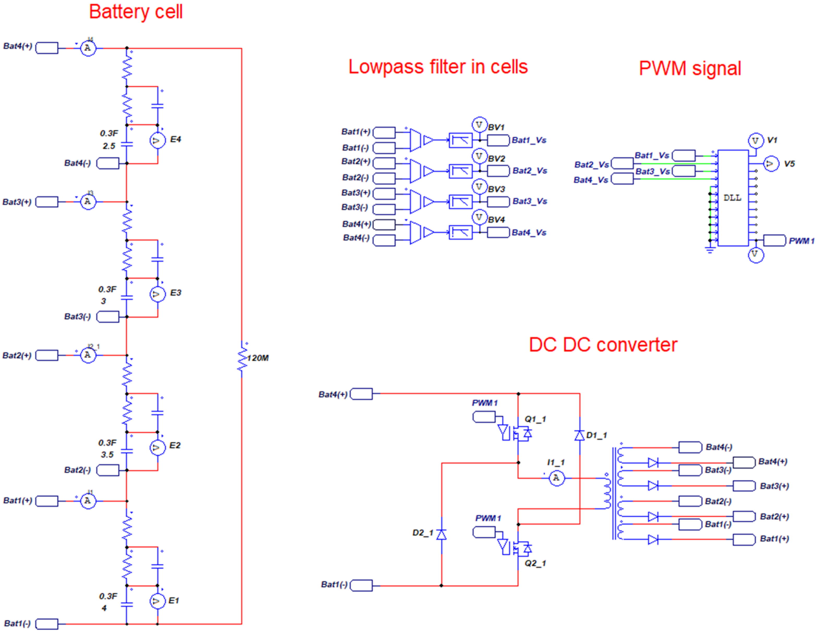
2. Power Converter for Battery Charging

2.1. Battery Model

In the initial stage of charging, a redox reaction occurs through an electrochemical reaction on the electrode surface and spreads, and the battery is charged in the CC constant current mode. After reaching the final voltage value through the charging process, charging takes place in the CV constant voltage mode. If the diffusion model is applied to implement this phenomenon in the form of a battery cell model on a circuit, it can be considered as equivalent to an RC circuit with a parallel structure. Therefore, cell charging is a method of spreading after application of the maximum charging voltage and a large current in the form of a pulse [25].
As the battery model in this study targets a charging current of less than 2 to 3 C, the simplified Randles model can be applied.
In the case of a diffusion model circuit, as shown in Figure 2b, by applying the Randles model, the internal resistance of a battery and the voltage drop that occurs during the charge transfer can be set equivalent to the integrated internal resistance rs. The factor for the electric double layer of the battery is equivalent to Cd, and the dislocation loss component can be set equivalent to rd.

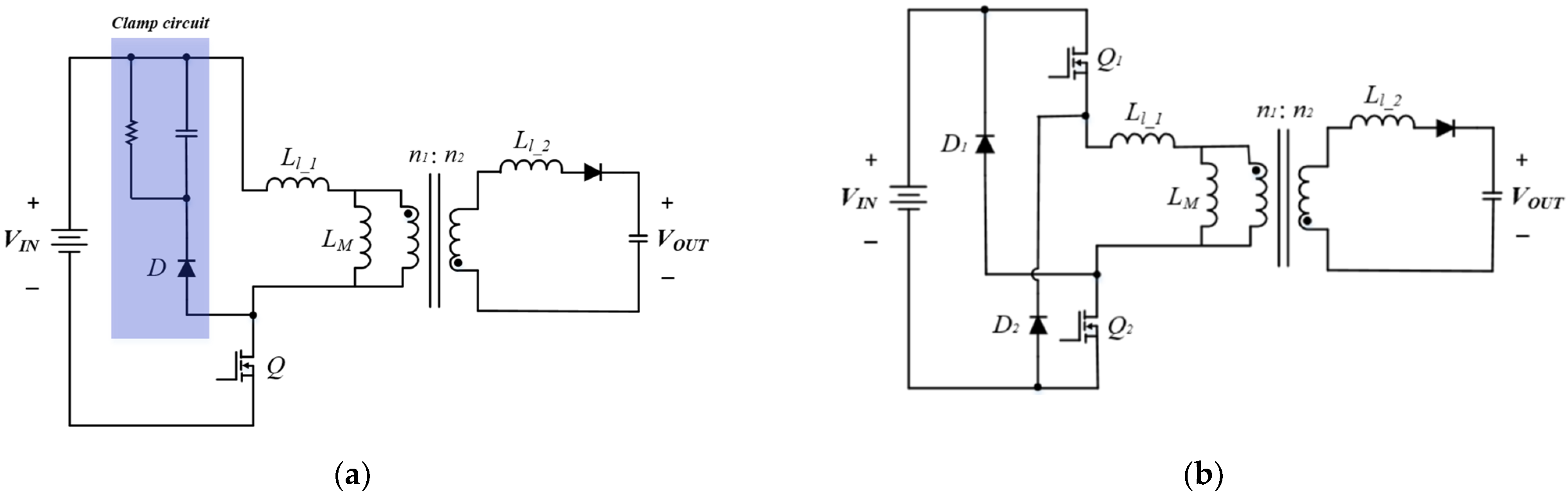
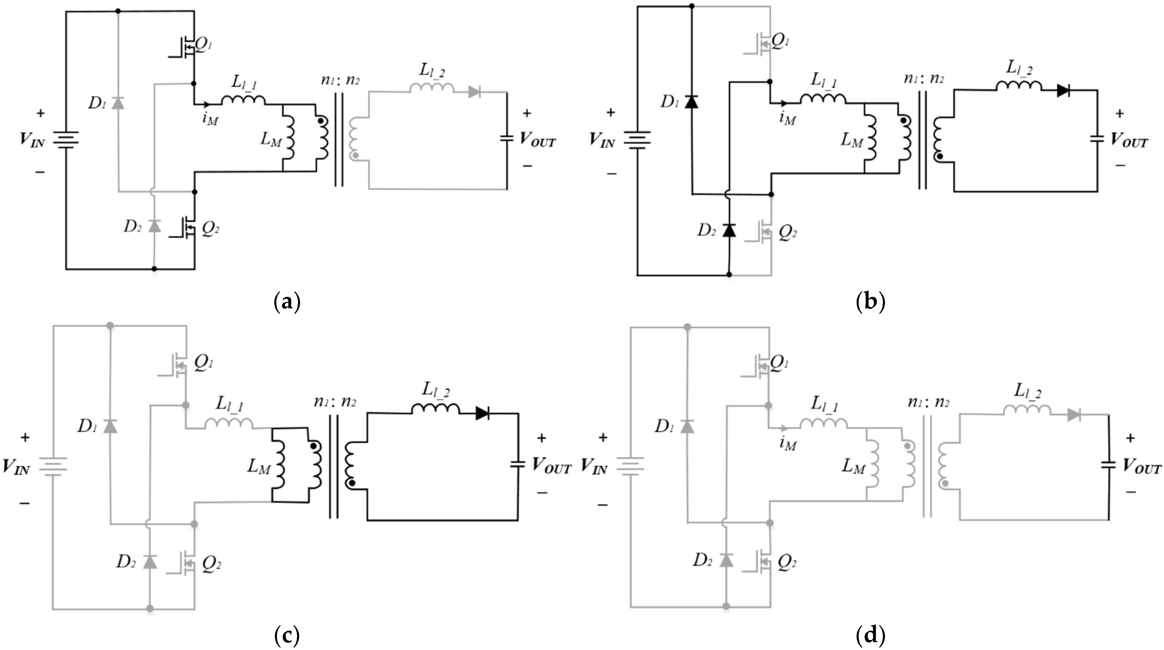
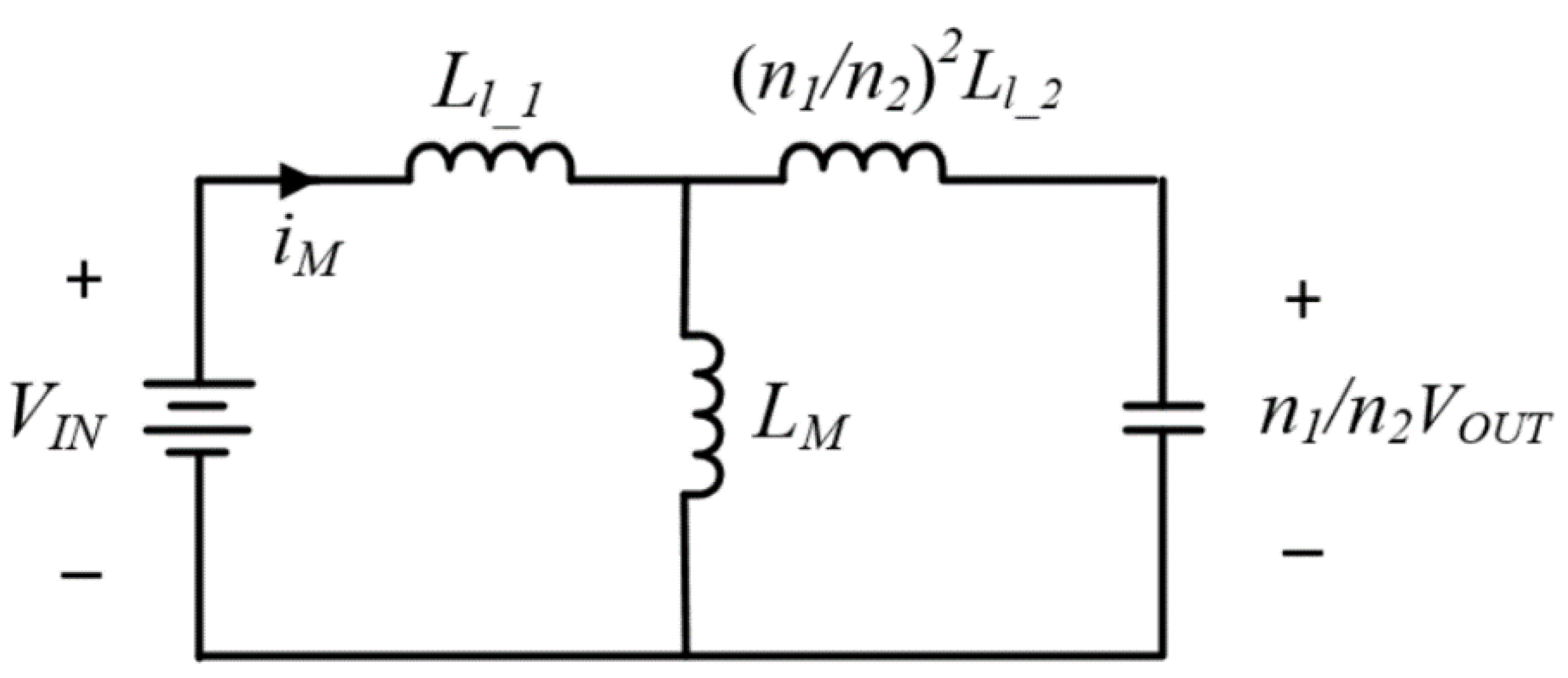
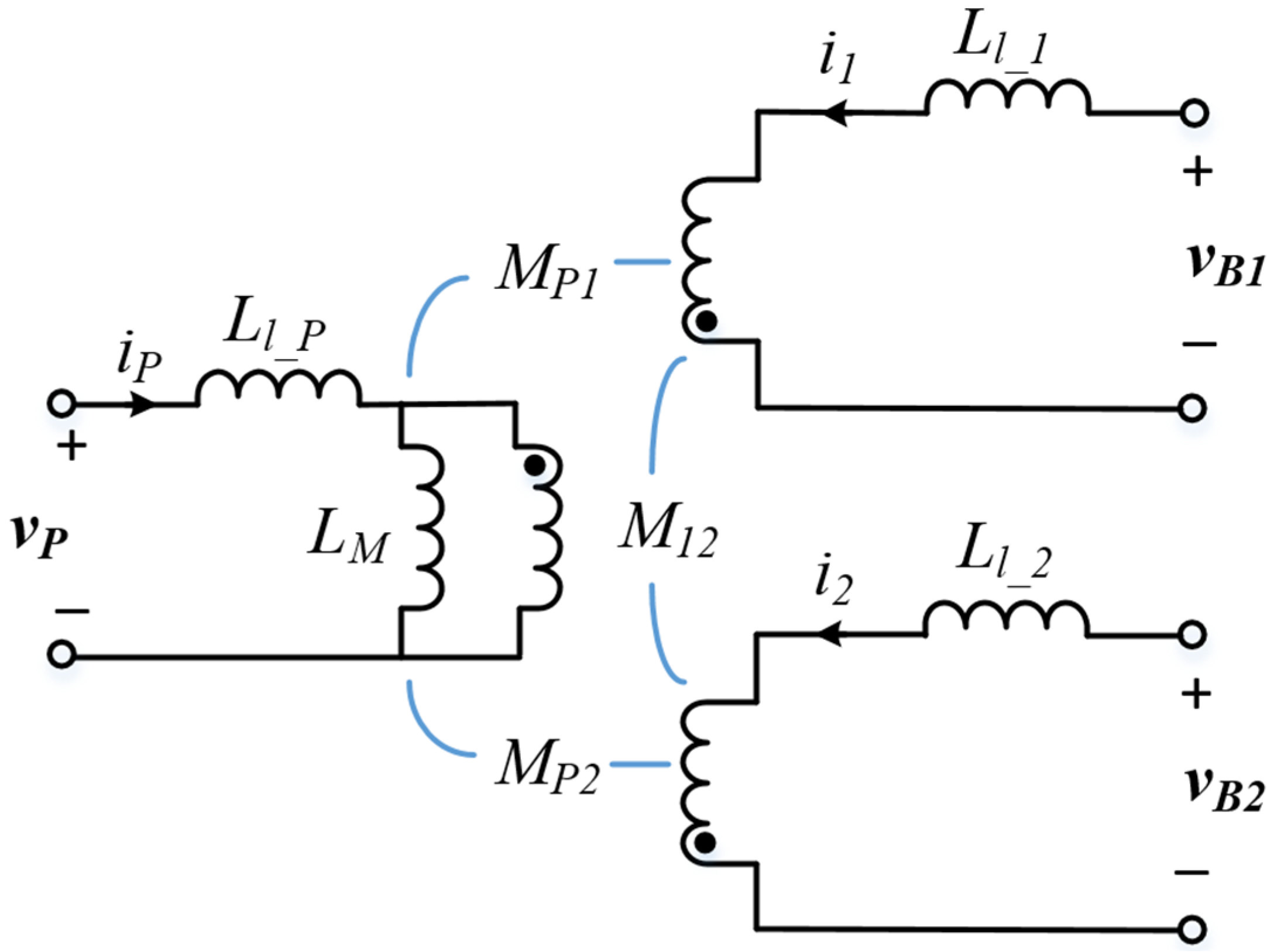
2.2. Flyback Converter for Cell Balancing

Figure 3a shows the circuit of a standard flyback converter based on a single switch. The transformer constituting this converter contains an actual magnetizing inductance LM and a leakage inductance Ll. It may cause excessive switch stress and a ringing formation in the switch due to the primary electric field effect, which may cause switch damage. Subsequently, the voltage stress that the switch receives is aggravated by the input voltage, the reflected voltage from the transformer, and the accumulated cutoff voltage from the leakage inductance. Therefore, a separate clamp circuit is required to mitigate voltage spikes and allow the magnetizing inductor current to flow when switched off. However, such a clamping circuit may consume power from the resistance element and limit the power efficiency of the converter in the long term. Moreover, the switching duty ratio is limited to less than 50%, and the transformer core must always reset each cycle.
The flyback converter applied in this study is the two-switch based flyback converter shown in Figure 3b. The main configuration of the circuit consists of two series-connected switches Q1 and Q2 and two freewheeling diodes D1 and D2 connected in a bridge form. When a given flyback converter circuit is configured as a circuit used for cell balancing, it becomes a structure, wherein four battery cells in one transformer are configured to share the same magnetic flux.
In the case of the cell balancing model using the existing flyback converter, the cell balancing circuit is composed of a circuit with the number of transformers accompanied by the number of cells, whereas in the proposed structure, the number of transformers can be reduced to one. In addition, through the shared magnetic flux, fast voltage synchronization is possible, and voltage detection is easy. Furthermore, the method of using two-switch flyback converters instead of a clamp circuit minimizes the effects of the spike voltage due to leakage compared with when using a conventional one-switch converter, thereby improving the battery performance.
The transformer of the circuit with the two-switch flyback topology has an actual magnetizing inductance component, and Figure 4 shows the operation mode of the flyback converter including one cell.
The principle of operation of the circuit is achieved through the simultaneous operation of two switches. In Figure 4a, when both switches Q1 and Q2 with ratio D are in operation at the same time, the primary winding of the transformer is connected to the input terminal, and the diode in the secondary winding has a reverse voltage applied across both ends. Thus, the current in the secondary winding of the transformer is blocked at this time, and the leakage energy flows through the freewheeling diode and is converted into reactive power. Accordingly, the power loss and the system noise are reduced. The inductor current can be represented as:
i M = V g L M D T s
where Vg is the input voltage, and Lm is the magnetizing inductance.
Figure 4b shows the simultaneous off operations of switches Q1 and Q2. As the current in the magnetizing inductor must continue to flow in the same direction even after the switch-on operation has been followed by an operation-off, the inductor current is recovered at the input terminal, which is along the two freewheeling diodes. The inductor current iM decreases linearly. Figure 5 shows the equivalent circuit when Q1 and Q2 are off under the condition that the primary side current is greater than zero.
i M = n 1 n 2 V g L M ( 1 D ) T s
The current isec of the secondary winding transformer is as in Equation (3).
i sec = n 1 n 2 V g V o u t L l _ 2
where Ll_2 is the leakage inductance of the secondary side transformer, and Vout is the output voltage of the secondary side of the transformer. The leakage energy is refluxed along the diode and converted into reactive power, thereby reducing power loss and system noise.
Whether the operation mode in this stage is determined depends on whether the step-down converter condition is the same as in Equation (4), so the operation mode starts in the state where the given condition is satisfied.
V I N > n 1 n 2 V O U T
Therefore, under the condition that Equation (4) is satisfied, as the diodes on the secondary winding side of the transformer conduct electricity by inverting the voltage, the energy of the primary side is transferred to the secondary side. Additionally, the voltage equation for the secondary-side current is the same as Equation (5).
[ V I N V O U T ] = [ ( L l _ 1 + L M ) L M n 2 n 1 L M ( n 1 n 2 L l _ 1 + n 2 n 1 L M ) ] [ i M i sec ]
From (5), the primary-side current iM is as follows.
i M = V O U T = 1 X { ( n 2 n 1 L l _ 2 + L M ) V I N + n 1 n 2 L M V O U T }
with
X = V O U T = ( n 1 n 2 ) 2 L l _ 2 ( L l _ 1 + L M ) + L l _ 1 L M
The circuit operation in this stage ends when the transformer primary current becomes zero. Thereafter, as shown in Figure 4c, the inductor voltage becomes zero. As the current in the primary-side transformer converges to zero, the amount of energy transfer in the magnetizing inductor gradually decreases, and eventually, all currents in the flyback converter become zero, as shown Figure 4d. Subsequently, the switches Q1 and Q2 simultaneously repeat the turn-on operation mode.

2.3. Cell Balancing Control

Figure 6a,b show the circuit operation mode of the single-input selective-output (SISO) two -switch flyback converter-based circuit used for battery balancing in this study. The characteristic of this topology is that each of the four battery cells constituting one module shares a magnetic flux through a high-frequency transformer; accordingly, the voltage between the cells is synchronized according to the converter switch operation in case of voltage imbalance.
Cell voltage balancing control starts with a transfer of transformer energy to the secondary cell stage when the converter switches Q1 and Q2 are off. Therefore, the energy accumulated in the transformer during the switch-on operation is transferred to the cell stage through the transformer along with the current flowing along the converter diode.
Subsequently, in a voltage imbalance situation between cells, the energy of the transformer is synchronized to the same value through the transformer sharing the same magnetic flux. Therefore, as shown in Figure 7a, the cell voltage is differentially charged and distributed, and the charge is distributed differentially according to the difference between the cell voltages.
In contrast, when a given cell voltage exceeds a certain value, there is a need to automatically stop charging to prevent overcharging of the battery cells. Therefore, as shown in Figure 7b, energy exceeding the maximum charged voltage is converted into reactive power and refluxed to the power supply side, thereby stopping voltage distribution between the cells.
In the switch-on operation, the primary-side energy is applied to the transformer coil. At this time, the polarity of the applied voltage is determined according to the direction of the current, and its magnitude is determined by the time ratio of the switch. Meanwhile, in the circuit, the charging process for balancing the cells is actually performed when the converter switch is off. In Figure 8, assuming a circuit composed of two cells, m and l, with two different charging voltages at a specific point in time, energy moves from the cell with a high charging voltage to the cell with a low charging voltage when the switch is off. This charging principle is applicable to determine the amount and direction of cell energy charging and discharging even when the number of cells is further expanded.
Then, when the charging voltage vm of cell m is greater than the charging voltage vl of cell l, the charging current equation is the same as Equation (7).
i m l = v m v l L l
where Ll is the leakage inductance, which acts as a driving impedance that limits electrical flow.
The equivalent circuit of a three-winding transformer based on a circuit with two cells when the converter is switched off is shown in Figure 8.
At this time, the cell output voltage is as shown in Equations (8)–(10) under the following magnetizing inductance conditions shown in Figure 9.
v P = L P d i P d t + a M p 1 d d t ( i 1 a ) + b M P 2 d d t ( i 2 b )
v 1 = a L 1 d d t ( i 1 a ) + M p 1 d i P d t + b M 12 d d t ( i 2 b )
v 2 = L P d i P d t + a M p 1 d d t ( i 1 a ) + b M P 2 d d t ( i 2 b )
with
a = M P 2 M 12 ,   b = M P 1 M 12
The same principle can be applied when the number of cells is expanded to n by increasing the number of windings on the secondary side.

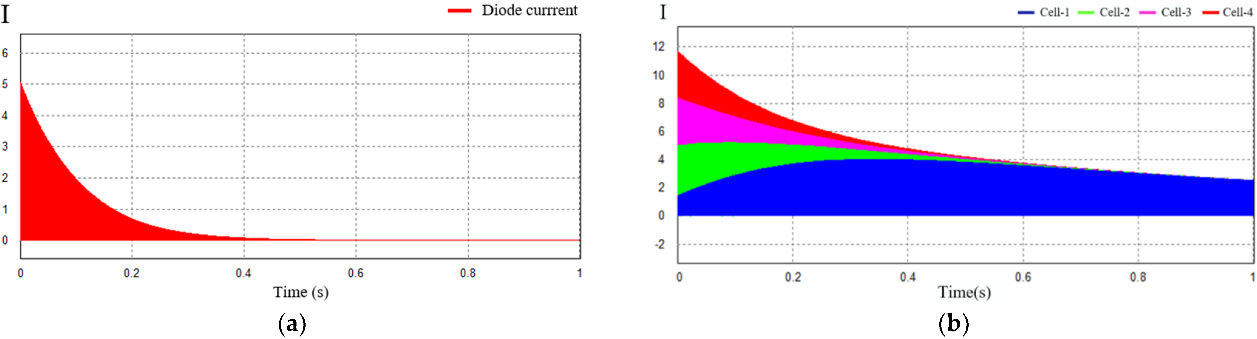
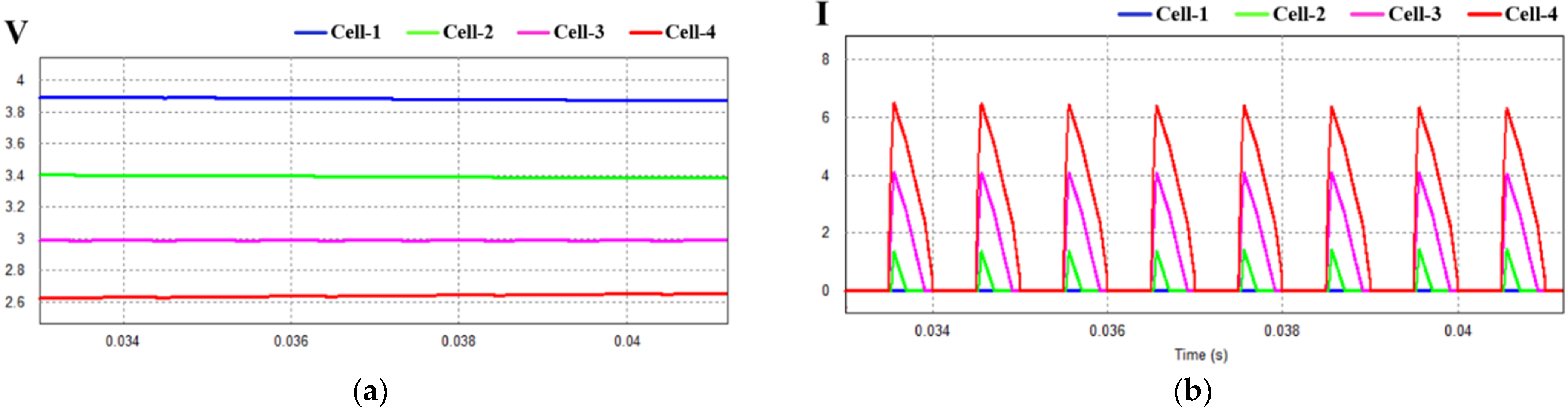
3. Simulation and Experimental Verification

The dynamic characteristic analysis of the proposed two-switch flyback with flux-sharing transformer for voltage balancing topology was verified through simulations using PSIM and experiments. Figure 10 shows the circuit for simulation verification, and it is assumed that the four battery cells each have different initial voltage values. The battery constituting the cell was replaced with a capacitor having a capacity of 500 μF, and it was designed with a transformer turns ratio of 3 to 1. In the operation of the power semiconductor, the switching duty ratio was set to 0.4, the switching frequency was 10 kHz, and each cell was equipped with a lowpass filter.
Figure 11 is a simulation result showing the simulated cell current and the primary-side diode current to analyze the characteristics of voltage balancing of a circuit based on a battery cell with an initial voltage value without an external voltage source. When the switches Q1 and Q2 of the flyback converter are turned off, the transformer current flows back along the diode, and the current flows through the secondary-side transformer to charge the inside of the cell. As for the cell current, it can be seen that the smallest charging current flows in cell 1, which is the cell with the highest initial capacitor voltage, while the largest charging current flows in cell 4, which has the lowest initial voltage.
Figure 12 shows the change in cell voltage through balancing control. In the absence of an external voltage source, the voltage imbalance condition according to the switch operation occurs in 0.34 s, and the balanced voltage value is 3.29 V, as shown in Equation (8). That is, it is confirmed that the cell voltage decreases in the case of a cell with a high initial voltage, whereas the cell with a low initial voltage receives more energy and converges to the same value in the equilibrium state.
V B A = V B A _ 1 2 + V B A _ 2 2 + V B A _ 3 2 + V B A _ 4 2 4
Figure 13 shows the waveform of the converter current when voltage balancing is performed. Figure 13a shows the currents of the primary and secondary circuits of the converter transformer. When the switch is turned on, the converter current is stored in the transformer without being transferred to the secondary circuit of the transformer and is the same as the switch-off operation. It shows the positive transfer to the secondary-side transformer. Figure 13b shows the current flowing on the diode of the secondary circuit.
Figure 14 shows an enlarged graph of each battery cell voltage and current in the area wherein balancing is performed in the initial state during cell balancing control. When the cell balancing circuit is in operation, in the case of cell 1 having the largest initial voltage value, there is little inflow of current to the secondary circuit cell. However, in the case of cell 4 having the smallest initial voltage value, most of the energy is transferred from the cell. Accordingly, this shows that balancing between the battery cells is being achieved.
Figure 15a shows an experimental set to verify the voltage cell balancing circuit. The SOC constituting the experimental setup consists of a capacitor, a two-switch flyback DC/DC converter, and a transformer in each cell simulating a battery, and each cell has a load resistance of 10 Ω in Figure 15b. At this time, the initial voltages of capacitors C1, C2, C3, and C4 constituting the four cell models were set to 2.7 V, 2.76 V, 3 V, and 3.8 V. Table 1 lists the experimental conditions for proposed topology.
Figure 16a shows the voltage balancing results of cells with different initial voltage values. In the experiment, the voltage values of four cells with different initial voltage values were balanced for a period of 320 ms. In addition, it was possible to shorten the balancing time by varying the capacity of the capacitor of the actual battery cell model. When looking at the two cells as a standard, the situation in which the current moves from cell 1 with a high initial voltage to cell 3 with a low initial voltage can be seen. This voltage balancing operation appears repeatedly in the converter switch-off operation. Additionally, after voltage balancing through the experiment, the balanced voltage value was confirmed as 3 V, which was the value calculated in Equation (8).
Figure 16b shows the cell current waveform during the voltage balancing control operation.
Figure 17 shows the experimental results of the cell balancing operation. That is, it shows the current waveform of cell 1 that appears in the switch operation controlled by PWM control in the normal state.

4. Conclusions

In this study, a voltage balancing topology using a two-switch flyback converter through a single-input multi-output transformer was proposed. The proposed voltage balancing circuit was the current source for a two-switch flyback converter and was connected to a series of four battery cells in a secondary circuit at the converter input stage. Furthermore, the four cells were combined in one high-frequency transformer for sharing the same magnetic flux. Based on experiments and a simulation verification for the validation of these topology circuits, it was confirmed that voltage balancing was performed automatically by the switch operation without additional cell voltage information in the process of voltage balancing. In addition, it was shown that the power in the excitation inductance generated during the switch operation was converted into reactive power and recovered so that it could be used as a limiting factor for the possibility of an excessive charging voltage.
As the proposed structure shares the same magnetic flux at the same time rather than in a vertically sequential control, if a larger capacity of the entire cell is required for a specific purpose, cell expansion is possible through the module using the same balancing principle. Therefore, the ESS with higher voltage/current capacity can be applied to the utilization of the system.

Author Contributions

Conceptualization, S.-J.P.; methodology, U.-J.K. and S.-J.P.; software, U.-J.K. and S.-J.P.; validation, U.-J.K. and S.-J.P.; formal analysis, U.-J.K.; investigation, U.-J.K. and S.-J.P.; resources, S.-J.P.; data curation, U.-J.K.; writing—original draft preparation, U.-J.K.; writing—review and editing, U.-J.K. and S.-J.P.; visualization, U.-J.K.; supervision, S.-J.P.; project administration, S.-J.P. All authors have read and agreed to the published version of the manuscript.

Funding

This research was funded by Korea Institute of Energy Technology Evaluation and Planning (KETEP), grant number 29214000000560.

Institutional Review Board Statement

Not applicable.

Informed Consent Statement

Informed consent was obtained from all subjects involved in the study.

Conflicts of Interest

The authors declare no conflict of interest. The funders had no role in the design of the study.

References

  1. Yusof, M.S.; Toha, S.; Kamisan, N.; Hashim, N.; Abdullah, M.A. Battery cell balancing optimisation for battery management system. In IOP Conference Series: Materials Science and Engineering; IOP Publishing: Bristol, UK, 2017; p. 012021. [Google Scholar]
  2. Deng, J.; Bae, C.; Denlinger, A.; Miller, T. Electric vehicles batteries: Requirements and challenges. Joule 2020, 4, 511–515. [Google Scholar] [CrossRef]
  3. Eyer, J.; Corey, G. Energy storage for the electricity grid: Benefits and market potential assessment guide. Sandia Natl. Lab. 2010, 20, 5. [Google Scholar]
  4. Na, J.K.; Na, K.S.; Lee, H.J.; Ko, Y.S.; Won, C.Y. Power conversion system control method for hybrid ESS. In Proceedings of the 2014 IEEE Conference and Expo Transportation Electrification Asia-Pacific (ITEC Asia-Pacific), Beijing, China, 31 August–3 September 2014; pp. 1–5. [Google Scholar]
  5. Ogunniyi, E.O.; Pienaar, H.C.V.Z. Overview of battery energy storage system advancement for renewable (photovoltaic) energy applications. In Proceedings of the 2017 International Conference on the Domestic Use of Energy (DUE), Cape Town, South Africa, 4–5 April 2017; pp. 233–239. [Google Scholar]
  6. Yang, Y.; Yao, M.; Wang, Q. Research on dynamic impedance characteristics of hybrid vehicle battery. In Proceedings of the 2014 IEEE International Conference on Industrial Technology (ICIT), Busan, Korea, 26 February–1 March 2014; pp. 810–815. [Google Scholar]
  7. Hassan, M.; Jawad, M.; Saleem, N.; Raza, A.; Zaidi, K.; Rafiq, N. Solar Power Assisted Passive and Active Cell Balancing System: A Comprehensive Analysis. In Proceedings of the 2021 International Conference on Frontiers of Information Technology (FIT), Islamabad, Pakistan, 13–14 December 2021; pp. 224–229. [Google Scholar]
  8. Ouyang, Q.; Han, W.; Zou, C.; Xu, G.; Wang, Z. Cell balancing control for lithium-ion battery packs: A hierarchical optimal approach. IEEE Trans. Ind. Inform. 2019, 16, 5065–5075. [Google Scholar] [CrossRef]
  9. Shah, S.; Murali, M.; Gandhi, P. A practical approach of active cell balancing in a battery management system. In Proceedings of the 2018 IEEE International Conference on Power Electronics, Drives and Energy Systems (PEDES), Chennai, India, 18–21 December 2018; pp. 1–6. [Google Scholar]
  10. Omariba, Z.B.; Zhang, L.; Sun, D. Review of battery cell balancing methodologies for optimizing battery pack performance in electric vehicles. IEEE Access 2019, 7, 129335–129352. [Google Scholar] [CrossRef]
  11. Kim, M.-Y.; Kim, J.-W.; Kim, C.-H.; Cho, S.-Y.; Moon, G.-W. Automatic charge equalization circuit based on regulated voltage source for series connected lithium-ion batteries. In Proceedings of the 8th International Conference on Power Electronics-ECCE Asia, Jeju, Korea, 30 May–3 June 2011; pp. 2248–2255. [Google Scholar]
  12. Pei, Z.; Zhao, X.; Yuan, H.; Peng, Z.; Wu, L. An equivalent circuit model for lithium battery of electric vehicle considering self-healing characteristic. J. Control. Sci. Eng. 2018, 2018, 5179758. [Google Scholar] [CrossRef] [Green Version]
  13. Khanal, A.; Timilsina, A.; Paudyal, B.; Ghimire, S. Comparative Analysis of Cell Balancing Topologies in Battery Management Systems. In Proceedings of the IOE Graduate Conference, Lisbon, Portugal, 19–21 June 2019; pp. 845–851. [Google Scholar]
  14. Jeong, E.; Yang, C.; Han, S.; Kim, H. Battery Cell Balancing with Hybrid Architecture of Serial and Parallel Charging. KEPCO J. Electr. Power Energy 2016, 2, 609–613. [Google Scholar]
  15. Hemavathi, S. Overview of cell balancing methods for Li-ion battery technology. Energy Storage 2020, 203, 1–12. [Google Scholar]
  16. Daowd, M.; Omar, N.; Bossche, P.V.D.; Van Mierlo, J. Passive and active battery balancing comparison based on MATLAB simulation. In Proceedings of the 2011 IEEE Vehicle Power and Propulsion Conference, Chicago, IL, USA, 6–9 September 2011; pp. 1–7. [Google Scholar]
  17. Di Rienzo, R.; Zeni, M.; Baronti, F.; Roncella, R.; Saletti, R. Passive balancing algorithm for charge equalization of series connected battery cells. In Proceedings of the 2020 2nd IEEE International Conference on Industrial Electronics for Sustainable Energy Systems (IESES), Cagliari, Italy, 1–3 September 2020; pp. 73–79. [Google Scholar]
  18. Shukla, A.P.; Patel, R.A. Battery Management System by Passive Cell Balancing for Electric vehicle. In Proceedings of the 2022 2nd International Conference on Power Electronics & IoT Applications in Renewable Energy and Its Control (PARC), Mathura, India, 21–22 January 2022; pp. 1–6. [Google Scholar]
  19. Chandrakala, K.M.V. Active Cell Balancing Technique for Improved Charge Equalization in Lithium-Ion Battery Stack. In Proceedings of the 2021 4th International Conference on Recent Developments in Control, Automation & Power Engineering (RDCAPE), Noida, India, 7–8 October 2021; pp. 160–164. [Google Scholar]
  20. Banerjee, D.; Giri, A.; Saha, S.S. Active Cell Balancing of Li-Ion Batteries for Electric Vehicles. In Proceedings of the 2nd International Conference on Non-Conventional Energy: Nanotechnology & Nanomaterials for Energy & Environment (ICNNEE), Kolyani, India, 18–19 October 2019. [Google Scholar]
  21. Qays, M.O.; Buswig, Y.; Hossain, M.L.; Rahman, M.M.; Abu-Siada, A. Active cell balancing control strategy for parallelly connected LiFePO 4 batteries. CSEE J. Power Energy Syst. 2020, 7, 86–92. [Google Scholar]
  22. Leksono, E.; Haq, I.N.; Juliastuti, E.; Fahran, L.G.Z.; Nabhan, F.M. Development of Active Cell to Cell Battery Balancing System for Electric Vehicle Applications. In Proceedings of the 2019 6th International Conference on Electric Vehicular Technology (ICEVT), Bali, Indonesia, 18–21 November 2019; pp. 4–10. [Google Scholar]
  23. Du, G.; Zhang, G.; Yu, S.S.; Iu, H.H.; Lin, W.; Le, W.; Zhang, Y. An any-unit-to-any-unit method for hybrid-structured voltage equalizer in series-connected battery/super-capacitor strings. Int. J. Circuit Theory Appl. 2022, 50, 2016–2034. [Google Scholar] [CrossRef]
  24. Murthy-Bellur, D.; Kazimierczuk, M.K. Two-switch flyback-forward PWM DC-DC converter with reduced switch voltage stress. In Proceedings of the 2010 IEEE International Symposium on Circuits and Systems, Paris, France, 30 May–2 June 2010; pp. 3705–3708. [Google Scholar]
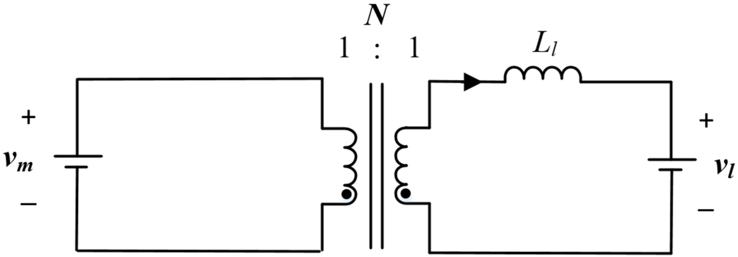
  25. Song, S.-G.; Park, S.-M.; Park, S.-J. New battery balancing circuit using magnetic flux sharing. J. Power Electron. 2014, 14, 194–201. [Google Scholar] [CrossRef] [Green Version]
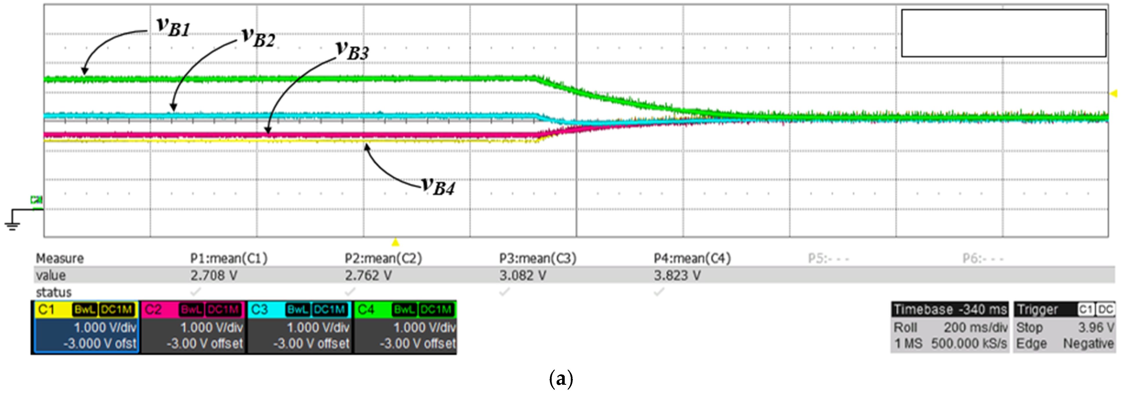
Figure 1. Conventional cell balancing methods. (a) passive method; (b) active method.
Energies 15 04806 g001
Figure 2. (a) CC-CV graph; (b) simplified battery equivalent circuit.
Energies 15 04806 g002
Figure 3. Two flyback converter with one switch. (a) one-switch flyback converter with clamp circuit; (b) two-switch flyback converter with clamp circuit.
Energies 15 04806 g003
Figure 4. Operation modes of the two-switch flyback converter. (a) Q1, Q2 on; (b) Q1, Q2 off (iM > 0); (c) Q1, Q2 off (iM = 0); (d) Q1, Q2 off (all current in converter = 0).
Energies 15 04806 g004
Figure 5. Equivalent circuit during Q1, Q2 off (iM > 0).
Energies 15 04806 g005
Figure 6. Operation modes of cell−balancing circuit: (a) switch on and (b) switch off.
Energies 15 04806 g006
Figure 7. Operation graph of voltage balancing (a) before balancing control and (b) after balancing control.
Energies 15 04806 g007aEnergies 15 04806 g007b
Figure 8. Voltage balancing between cells.
Energies 15 04806 g008
Figure 9. Multi transformer with cells.
Energies 15 04806 g009
Figure 10. Circuit for simulation and verification.
Energies 15 04806 g010
Figure 11. Circuit for simulation and verification (a) 1st diode current of converter; (b) battery cell current.
Energies 15 04806 g011
Figure 12. Battery cell voltage.
Energies 15 04806 g012
Figure 13. Converter characteristics. (a) Transformer and (b) diode current converter.
Energies 15 04806 g013
Figure 14. Cell characteristics (enlargement graph). (a) Cell voltage and (b) cell diode current.
Energies 15 04806 g014
Figure 15. Test setup for experiment. (a) Overall setup, (b) Gerber file.
Energies 15 04806 g015
Figure 16. Experiment results: (a) cell voltage (b) cell current.
Energies 15 04806 g016aEnergies 15 04806 g016b
Figure 17. Experiment results in normal state.
Energies 15 04806 g017
Table 1. Circuit Parameters for Experiment.
ParameterValues (Unit)
Initial voltage values of cell 12.7 V
Initial voltage values of cell 22.76 V
Initial voltage values of cell 33 V
Initial voltage values of cell 43.8 V
Capacitance7.5 F
Duty ratio0.42
Switching frequency10 kHz
Publisher’s Note: MDPI stays neutral with regard to jurisdictional claims in published maps and institutional affiliations.

