
Power Converter Topologies for Grid-Tied Solar Photovoltaic (PV) Powered Electric Vehicles (EVs)—A Comprehensive Review


Abstract
:1. Introduction
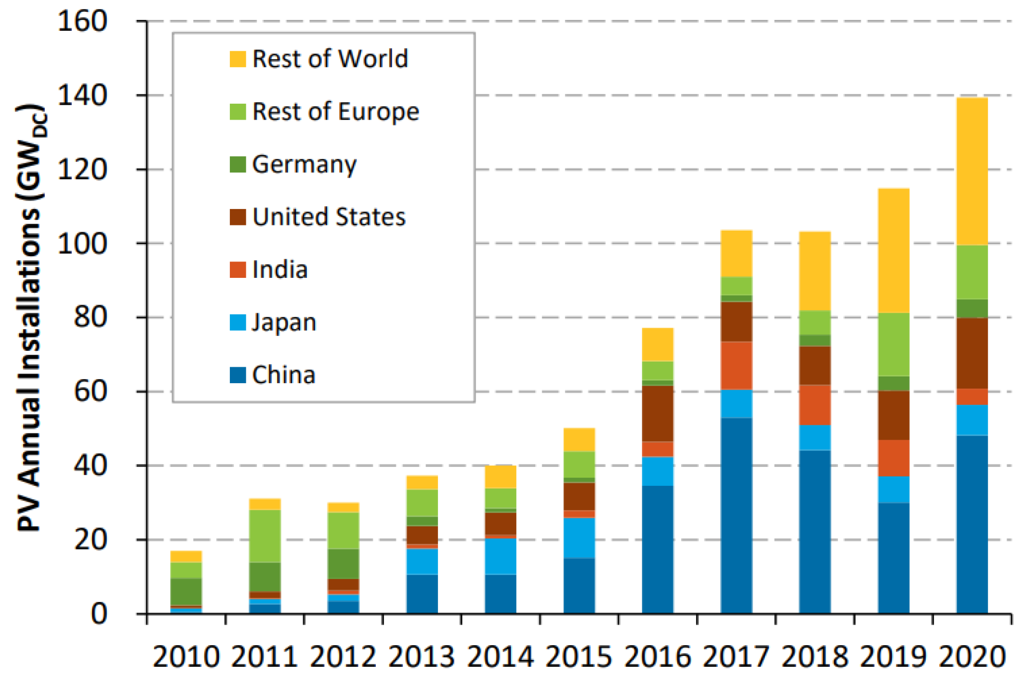
2. International Deployment of Solar Photovoltaic (SPV) Systems
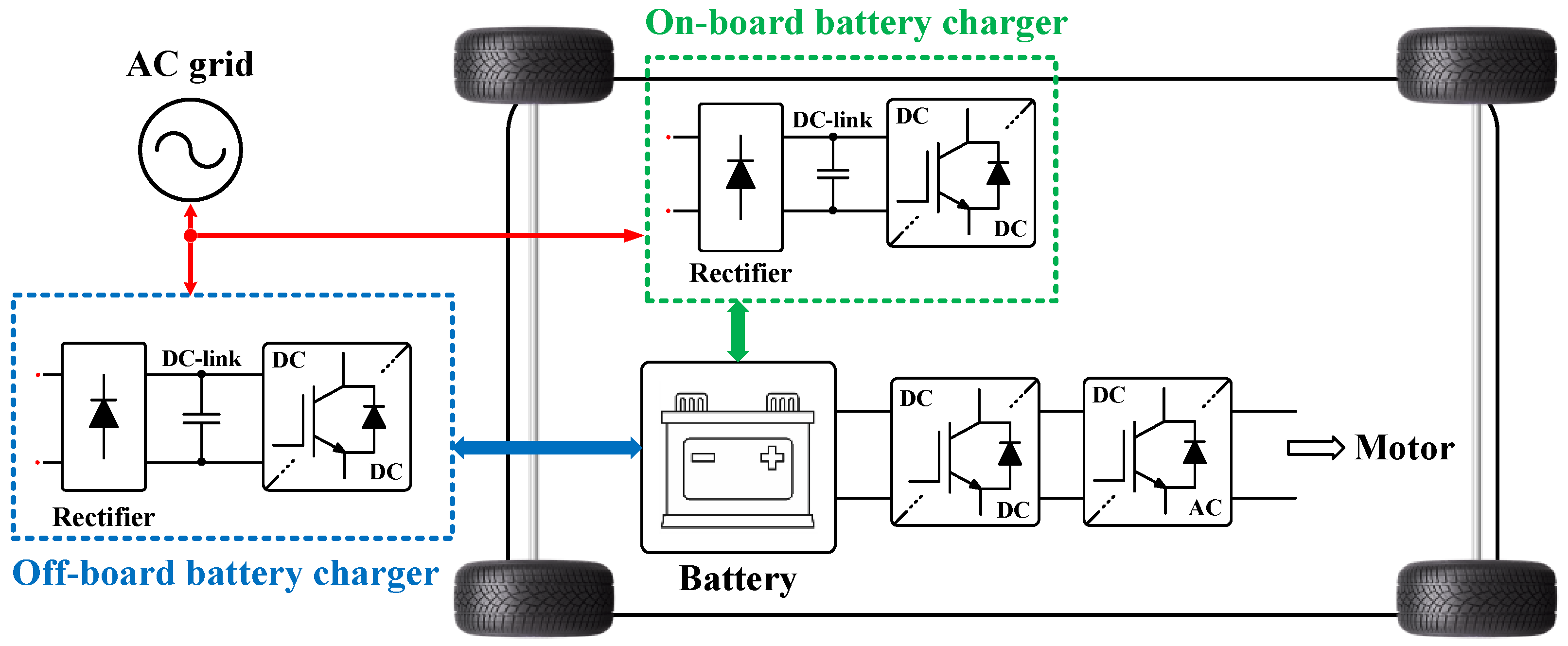
3. EVs Charger Types and Relevant Standards
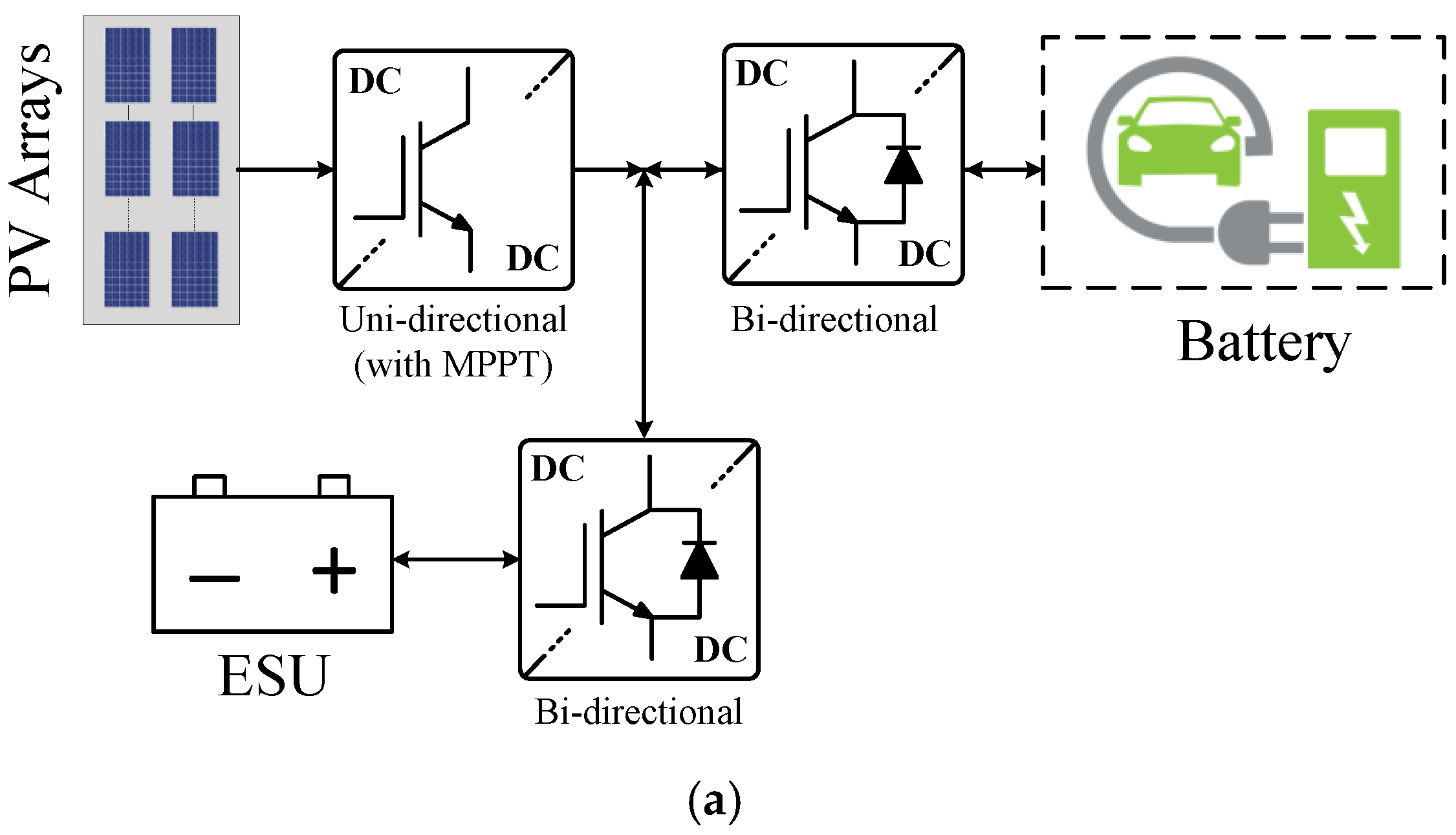
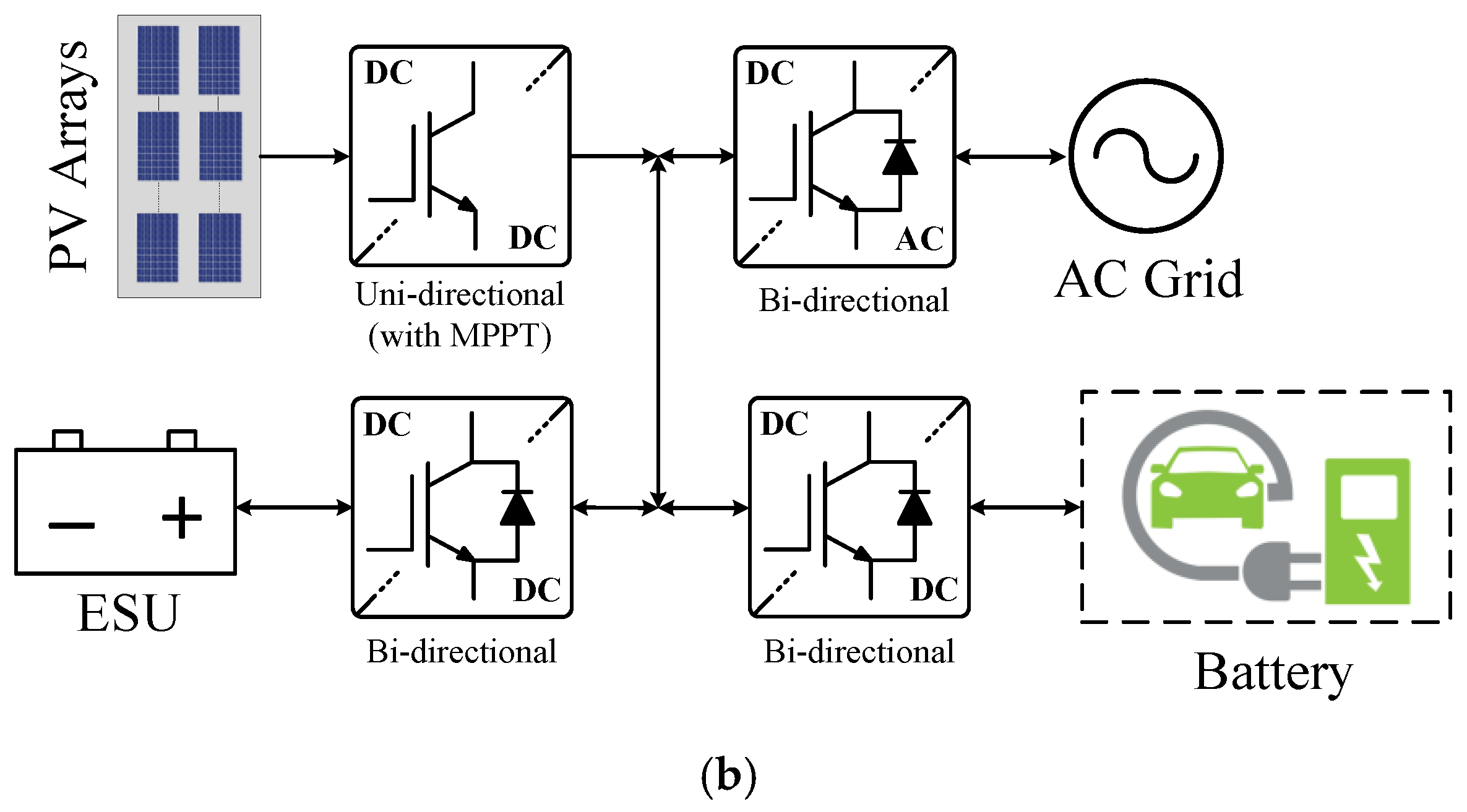
4. PV-Grid and Stand-Alone EV Charging
5. Converter Topologies for PV-Grid Charging Systems
5.1. Non-Integrated Architectures
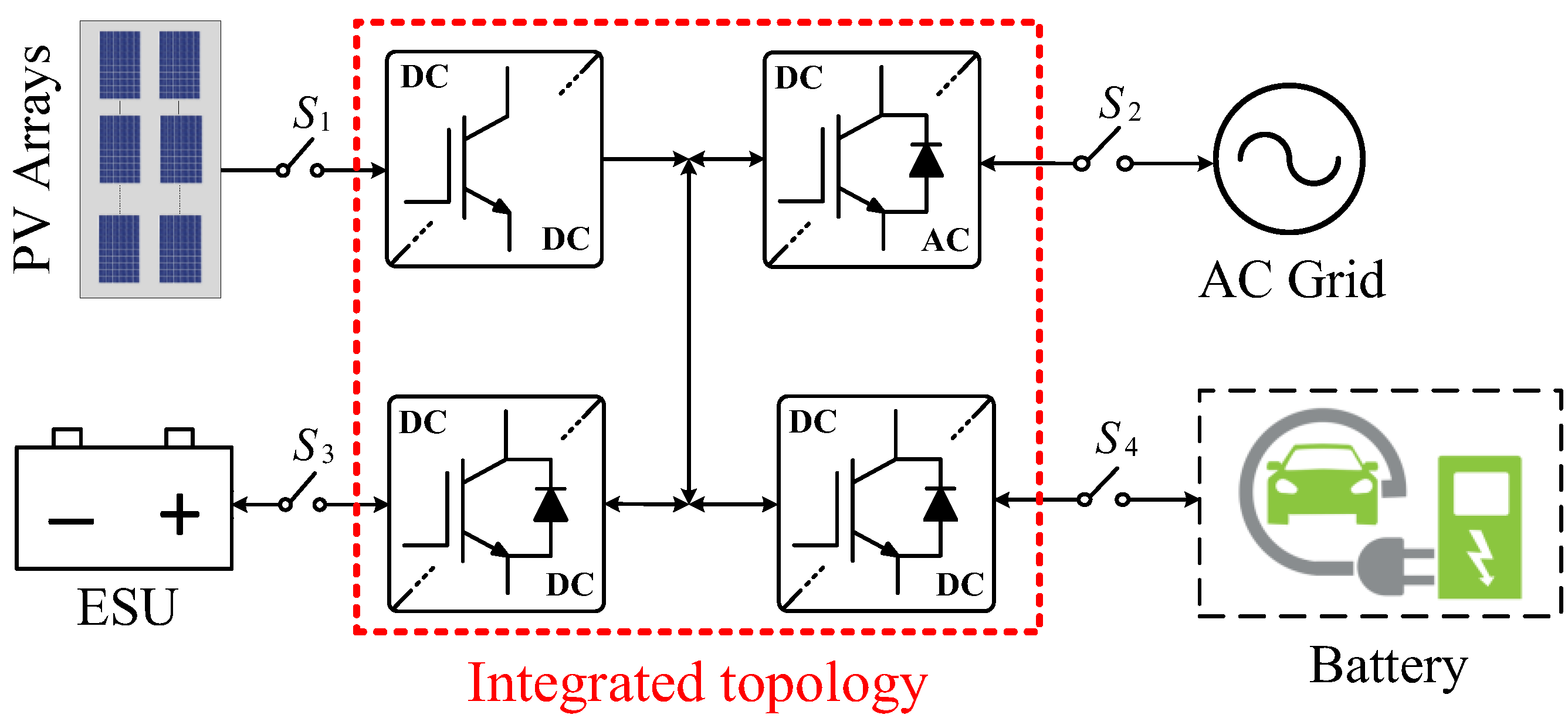
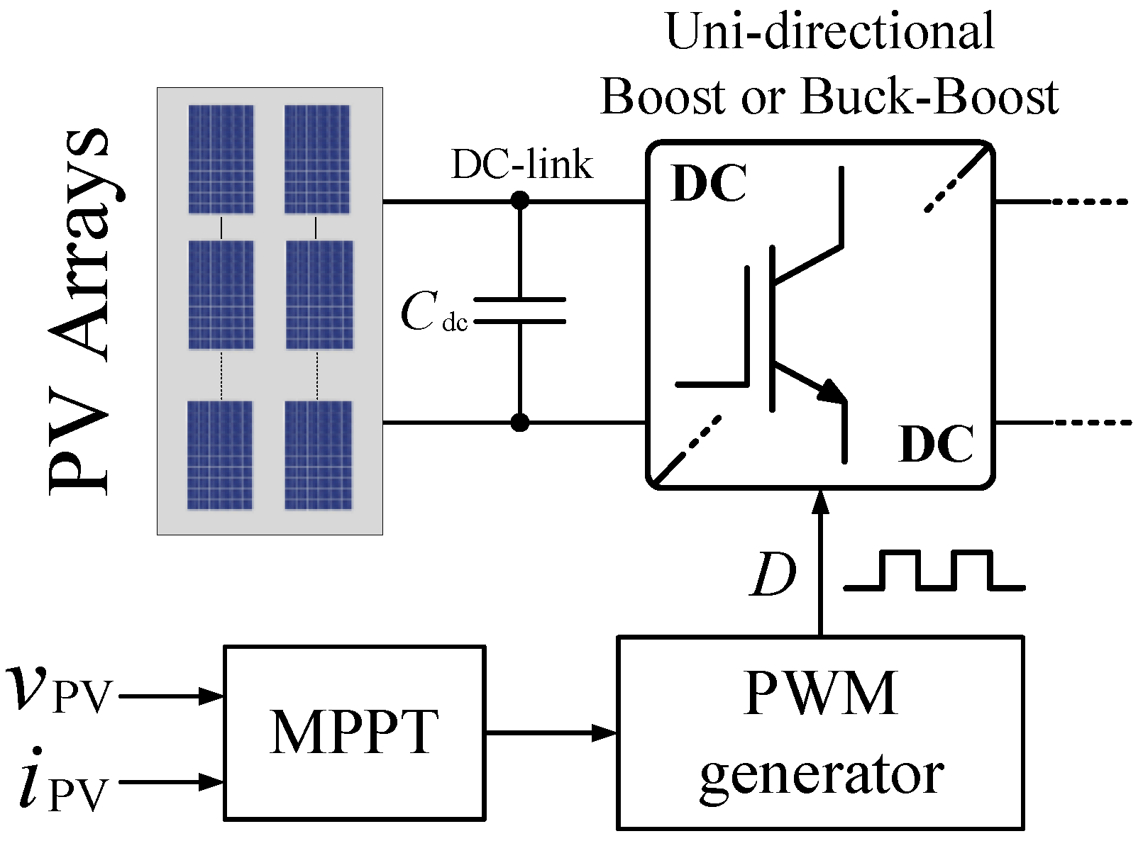
5.1.1. PV-Interfaced Converter Topologies
5.1.2. EV-Interfaced Converter Topologies
5.1.3. Grid-Interfaced Converter Topologies
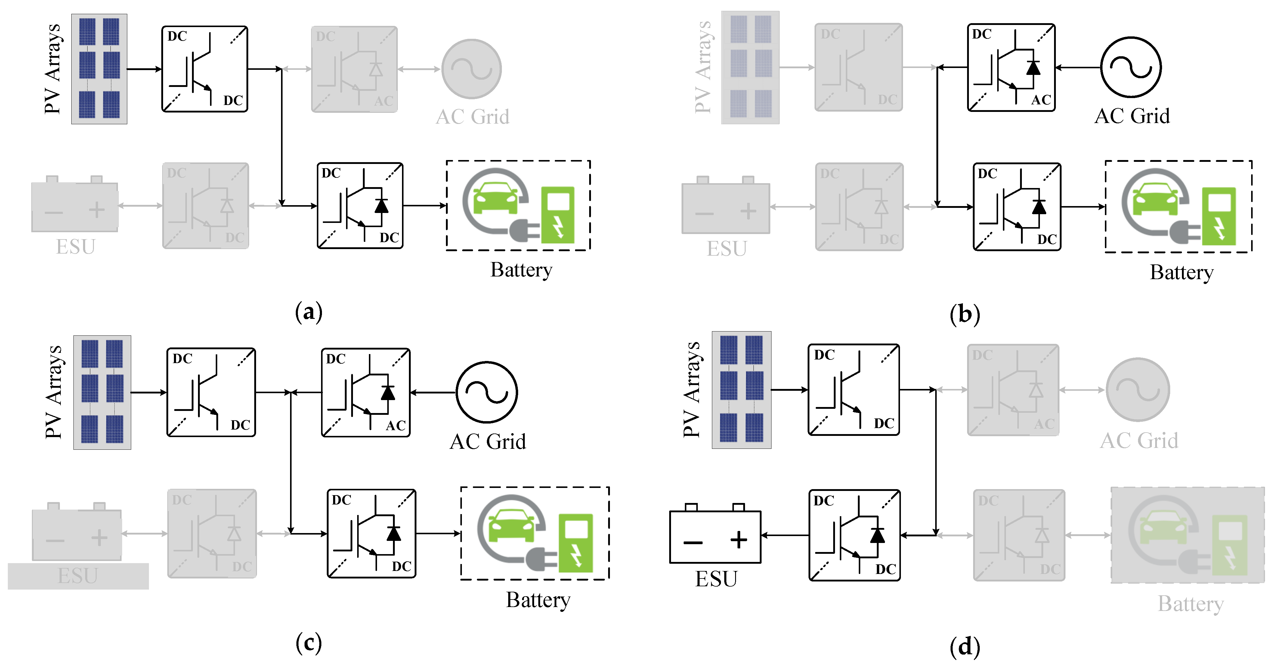
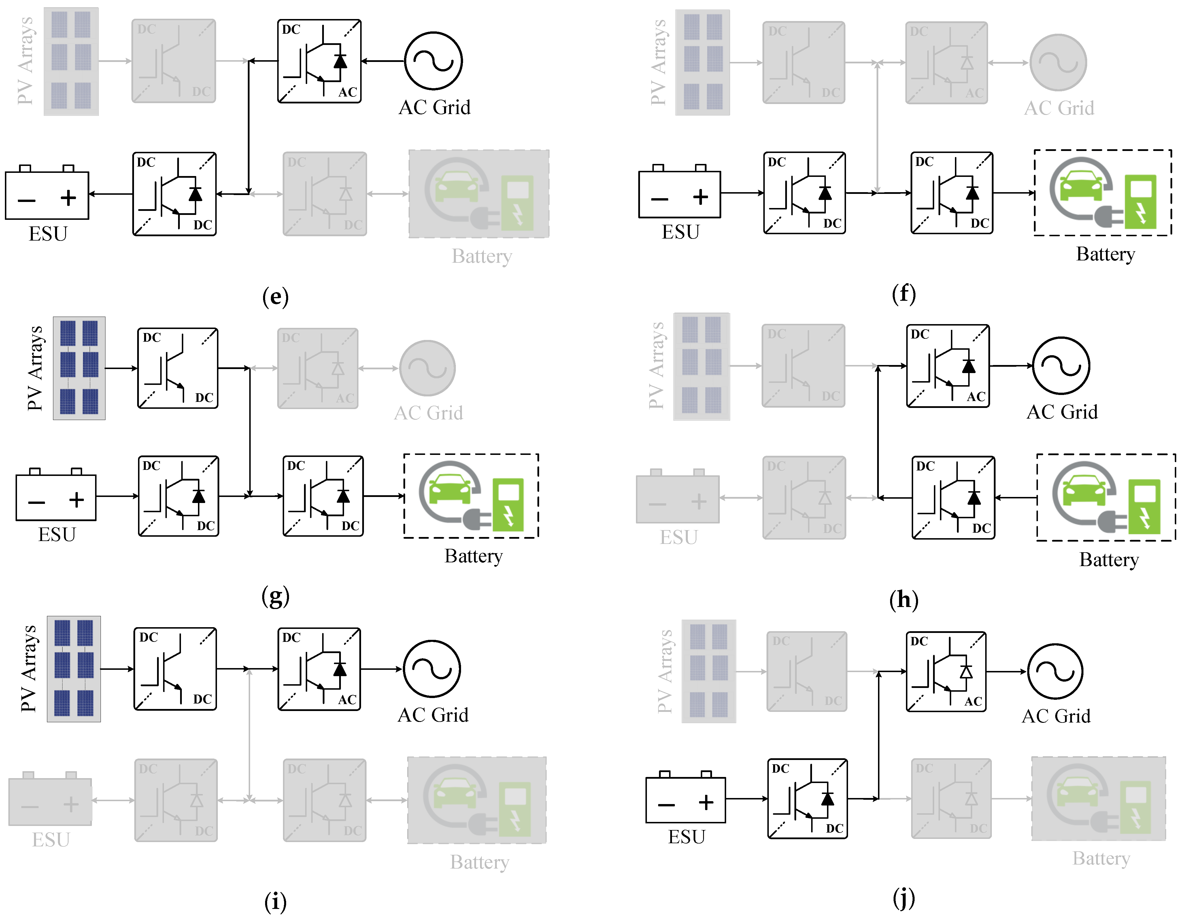
5.2. Integrated Architectures
6. Future Research
7. Conclusions
Author Contributions
Funding
Institutional Review Board Statement
Informed Consent Statement
Data Availability Statement
Conflicts of Interest
References
- Khan, S.; Ahmad, A.; Ahmad, F.; Shafaati Shemami, M.; Saad Alam, M.; Khateeb, S. A comprehensive review on solar powered electric vehicle charging system. Smart Sci. 2018, 6, 54–79. [Google Scholar] [CrossRef]
- Safayatullah, M.; Elrais, M.T.; Ghosh, S.; Rezaii, R.; Batarseh, I. A Comprehensive Review of Power Converter Topologies and Control Methods for Electric Vehicle Fast Charging Applications. IEEE Access 2022, 10, 40753–40793. [Google Scholar] [CrossRef]
- Bhatti, A.R.; Salam, Z.; Abdul, M.J.B.; Yee, K.P. A comprehensive overview of electric vehicle charging using renewable energy. Int. J. Power Electron. Drive Syst. 2016, 7, 114. [Google Scholar] [CrossRef]
- Global EV Outlook; International Energy Agency: Paris, France, 2021.
- Adhikari, M.; Ghimire, L.P.; Kim, Y.; Aryal, P.; Khadka, S.B. Identification and analysis of barriers against electric vehicle use. Sustainability 2020, 12, 4850. [Google Scholar] [CrossRef]
- Krishna, G. Understanding and identifying barriers to electric vehicle adoption through thematic analysis. Transp. Res. Interdiscip. Perspect. 2021, 10, 100364. [Google Scholar] [CrossRef]
- Verma, A.; Singh, B.; Chandra, A.; Al-Haddad, K. An implementation of solar PV array based multifunctional EV charger. IEEE Trans. Ind. Appl. 2020, 56, 4166–4178. [Google Scholar] [CrossRef]
- Ashique, R.H.; Salam, Z.; Aziz, M.J.B.A.; Bhatti, A.R. Integrated photovoltaic-grid dc fast charging system for electric vehicle: A review of the architecture and control. Renew. Sustain. Energy Rev. 2017, 69, 1243–1257. [Google Scholar] [CrossRef]
- Youssef, C.; Fatima, E.; Chakib, A. A technological review on electric vehicle DC charging stations using photovoltaic sources. In IOP Conference Series: Materials Science and Engineering; IOP Publishing: Bristol, UK, 2018; Volume 1, p. 012014. [Google Scholar]
- Şahin, A.D. Progress and recent trends in wind energy. Prog. Energy Combust. Sci. 2004, 30, 501–543. [Google Scholar] [CrossRef]
- Huang, Q.; Jia, Q.S.; Guan, X. A review of EV load scheduling with wind power integration. IFAC Pap. 2015, 48, 223–228. [Google Scholar] [CrossRef]
- Al Wahedi, A.; Bicer, Y. Development of an off-grid electrical vehicle charging station hybridized with renewables including battery cooling system and multiple energy storage units. Energy Rep. 2020, 6, 2006–2021. [Google Scholar] [CrossRef]
- Vassilev, S.V.; Vassileva, C.G.; Vassilev, V.S. Advantages and disadvantages of composition and properties of biomass in comparison with coal: An overview. Fuel 2015, 158, 330–350. [Google Scholar] [CrossRef]
- Blanco-Sanchez, P.; Taylor, D.; Cooper, S.; Hargreaves, N.; Bezanty, V.A. IEA Bioenergy Task 33; International Energy Agency: Paris, France, 2021. [Google Scholar]
- Shemami, M.S.; Alam, M.S.; Asghar, M.S.J. Load shedding mitigation through plug-in electric vehicle-to-home (V2H) system. In Proceedings of the 2017 IEEE Transportation Electrification Conference and Expo (ITEC), Chicago, IL, USA, 22–24 June 2017; pp. 799–804. [Google Scholar]
- Bouich, A.; Marí-Guaita, J.; Bouich, A.; Pradas, I.G.; Marí, B. Towards manufacture stable lead perovskite APbI3 (A= Cs, MA, FA) based solar cells with low-cost techniques. Eng. Proc. 2022, 12, 81. [Google Scholar]
- Singh, A.K.; Mishra, A.K.; Gupta, K.K.; Bhatnagar, P.; Kim, T. An integrated converter with reduced components for electric vehicles utilizing solar and grid power sources. IEEE Trans. Transp. Electrif. 2020, 6, 439–452. [Google Scholar] [CrossRef]
- Mouli, G.R.C.; Schijffelen, J.; van den Heuvel, M.; Kardolus, M.; Bauer, P. A 10 kW solar-powered bidirectional EV charger compatible with chademo and COMBO. IEEE Trans. Power Electron. 2018, 34, 1082–1098. [Google Scholar] [CrossRef] [Green Version]
- Bhatti, A.R.; Salam, Z.; Aziz, M.J.B.A.; Yee, K.P. A critical review of electric vehicle charging using solar photovoltaic. Int. J. Energy Res. 2016, 40, 439–461. [Google Scholar] [CrossRef]
- Bhatti, A.R.; Salam, Z.; Aziz, M.J.B.A.; Yee, K.P.; Ashique, R.H. Electric vehicles charging using photovoltaic: Status and technological review. Renew. Sustain. Energy Rev. 2016, 54, 34–47. [Google Scholar] [CrossRef]
- CHAdeMO Association. Technical Specifications of Quick Charger for the Electric Vehicle: CHAdeMO 1.0.1; CHAdeMO Association: Tokyo, Japan, 2013. [Google Scholar]
- SAE Standard J1772_201710; SAE Electric Vehicle and Plug-In Hybrid Electric Vehicle Conductive Charge Coupler. SAE International: Warrendale, PA, USA, 2010.
- Wang, L.; Qin, Z.; Slangen, T.; Bauer, P.; Wijk, T.V. Grid Impact of Electric Vehicle Fast Charging Stations: Trends, Standards, Issues and Mitigation Measures—An Overview. IEEE Open J. Power Electron. 2021, 2, 56–74. [Google Scholar] [CrossRef]
- Yilmaz, M.; Krein, P.T. Review of battery charger topologies, charging power levels, and infrastructure for plug-in electric and hybrid vehicles. IEEE Trans. Power Electron. 2012, 28, 2151–2169. [Google Scholar] [CrossRef]
- Singh, A.K.; Badoni, M.; Tatte, Y.N. A multifunctional solar PV and grid based on-board converter for electric vehicles. IEEE Trans. Veh. Technol. 2020, 69, 3717–3727. [Google Scholar] [CrossRef]
- Ul-Haq, A.; Cecati, C.; Al-Ammar, E.A. Modeling of a photovoltaic-powered electric vehicle charging station with vehicle-to-grid implementation. Energies 2016, 10, 4. [Google Scholar] [CrossRef]
- Soeiro, T.B.; Maia, G.J.; Ortmann, M.S.; Heldwein, M.L. High efficiency three-phase unidirectional bucktype PFC rectifier concepts. In Proceedings of the IECON 2013-39th Annual Conference of the IEEE Industrial Electronics Society, Vienna, Austria, 10–13 November 2013; pp. 7763–7768. [Google Scholar]
- Chae, B.; Kang, T.; Kang, T.; Suh, Y. Carrier based PWM for three-phase three-switch buck-type rectifier in EV rapid charging system. In Proceedings of the 2015 9th International Conference on Power Electronics and ECCE Asia (ICPE-ECCE Asia), Seoul, Korea, 1–5 June 2015; pp. 881–889. [Google Scholar]
- Baumann, M.; Kolar, J.W. Parallel connection of two three-phase three-switch buck-type unity-power-factor rectifier systems with dc-link current balancing. IEEE Trans. Ind. Electron. 2007, 54, 3042–3053. [Google Scholar] [CrossRef]
- Nussbaumer, T.; Kolar, J.W. Improving mains current quality for three-phase three-switch buck-type PWM rectifiers. IEEE Trans. Power Electron. 2006, 21, 967–973. [Google Scholar] [CrossRef]
- Lei, J.; Feng, S.; Zhao, J.; Chen, W.; Wheeler, P.; Shi, M. An improved three-phase buck rectifier topology with reduced voltage stress on transistors. IEEE Trans. Power Electron. 2019, 35, 2458–2466. [Google Scholar] [CrossRef]
- Chen, Q.; Xu, J.; Zeng, F.; Huang, R.; Wang, L. An Improved Three-Phase Buck Rectifier with Low Voltage Stress on Switching Devices. IEEE Trans. Power Electron. 2020, 36, 6168–6174. [Google Scholar] [CrossRef]
- Chen, Q.; Xu, J.; Wang, L.; Huang, R.; Ma, H. Analysis and improvement of the effect of distributed parasitic capacitance on high-frequency high-density three-phase buck rectifier. IEEE Trans. Power Electron. 2020, 36, 6415–6428. [Google Scholar] [CrossRef]
- Afsharian, J.; Xu, D.; Wu, B.; Gong, B.; Yang, Z. A new PWM and commutation scheme for one phase loss operation of three-phase isolated buck matrix-type rectifier. IEEE Trans. Power Electron. 2018, 33, 9854–9865. [Google Scholar] [CrossRef]
- Greul, R.; Round, S.D.; Kolar, J.W. Analysis and Control of a Three-Phase, Unity Power Factor Y-Rectifier. IEEE Trans. Power Electron. 2007, 22, 1900–1911. [Google Scholar] [CrossRef]
- Soeiro, T.B.; Kolar, J.W. Analysis of high-efficiency three-phase two-and three-level unidirectional hybrid rectifiers. IEEE Trans. Ind. Electron. 2012, 60, 3589–3601. [Google Scholar] [CrossRef]
- Huber, L.; Kumar, M.; Jovanovic, M.M. Analysis, design, and evaluation of three-phase three-wire isolated ac-dc converter implemented with three single-phase converter modules. In Proceedings of the 2016 IEEE Applied Power Electronics Conference and Exposition (APEC), Long Beach, CA, USA, 20–24 March 2016; pp. 38–45. [Google Scholar]
- Kolar, J.W.; Friedli, T. The essence of three-phase PFC rectifier systems. In Proceedings of the 2011 IEEE 33rd International Telecommunications Energy Conference (INTELEC), Amsterdam, The Netherlands, 9–13 October 2011; pp. 1–27. [Google Scholar]
- Zhang, B.; Xie, S.; Wang, X.; Xu, J. Modulation method and control strategy for full-bridge-based swiss rectifier to achieve ZVS operation and suppress low-order harmonics of injected current. IEEE Trans. Power Electron. 2019, 35, 6512–6522. [Google Scholar] [CrossRef]
- Friedli, T.; Hartmann, M.; Kolar, J.W. The essence of three-phase PFC rectifier systems—Part II. IEEE Trans. Power Electron. 2013, 29, 543–560. [Google Scholar] [CrossRef]
- Schrittwieser, L.; Kolar, J.W.; Soeiro, T.B. Novel SWISS rectifier modulation scheme preventing input current distortions at sector boundaries. IEEE Trans. Power Electron. 2016, 32, 5771–5785. [Google Scholar] [CrossRef]
- Halbig, J. 15kW Bidirectional Vienna PFC, 2014 IEEE Applied Power Electronics Conference and Exposition-APEC 2020 Presentations by STMicroelectronics, August 2020. Available online: https://www.st.com/content/dam/AME/2020/apec-2020/presentations/APEC2020_Vienna_Rectifier-virtual-FINAL.pdf (accessed on 21 June 2022).
- Huber, L.; Kumar, M.; Jovanović, M.M. Performance comparison of three-step and six-step PWM in average-current-controlled three-phase six-switch boost PFC rectifier. In Proceedings of the 2015 IEEE Applied Power Electronics Conference and Exposition (APEC), Charlotte, NC, USA, 15–19 March 2015; pp. 1861–1868. [Google Scholar]
- Mallik, A.; Ding, W.; Shi, C.; Khaligh, A. Input voltage sensorless duty compensation control for a three-phase boost PFC converter. IEEE Trans. Ind. Appl. 2016, 53, 1527–1537. [Google Scholar] [CrossRef]
- Xu, D.; Feng, B.; Li, R.; Mino, K.; Umida, H. A zero voltage switching SVM (ZVS–SVM) controlled three-phase boost rectifier. IEEE Trans. Power Electron. 2007, 22, 978–986. [Google Scholar] [CrossRef]
- Sha, D.; Xu, G.; Xu, Y. Utility direct interfaced charger/discharger employing unified voltage balance control for cascaded H-bridge units and decentralized control for CF-DAB modules. IEEE Trans. Ind. Electron. 2017, 64, 7831–7841. [Google Scholar] [CrossRef]
- Zheng, Z.; Wang, K.; Xu, L.; Li, Y. A hybrid cascaded multilevel converter for battery energy management applied in electric vehicles. IEEE Trans. Power Electron. 2013, 29, 3537–3546. [Google Scholar] [CrossRef]
- Qin, S.; Lei, Y.; Ye, Z.; Chou, D.; Pilawa-Podgurski, R.C. A high-power-density power factor correction front end based on seven-level flying capacitor multilevel converter. IEEE J. Emerg. Sel. Top. Power Electron. 2018, 7, 1883–1898. [Google Scholar] [CrossRef]
- Chou, D.; Fernandez, K.; Pilawa-Podgurski, R.C. An interleaved 6-level GaN bidirectional converter for level II electric vehicle charging. In Proceedings of the 2019 IEEE Applied Power Electronics Conference and Exposition (APEC), Anaheim, CA, USA, 17–21 March 2019; pp. 594–600. [Google Scholar]
- Kang, T.; Kim, C.; Suh, Y.; Park, H.; Kang, B.; Kim, D. A design and control of bi-directional non-isolated DC-DC converter for rapid electric vehicle charging system. In Proceedings of the 2012 Twenty-Seventh Annual IEEE Applied Power Electronics Conference and Exposition (APEC), Orlando, FL, USA, 5–9 February 2012; pp. 14–21. [Google Scholar]
- Rivera, S.; Wu, B.; Kouro, S.; Yaramasu, V.; Wang, J. Electric vehicle charging station using a neutral point clamped converter with bipolar DC bus. IEEE Trans. Ind. Electron. 2014, 62, 1999–2009. [Google Scholar] [CrossRef]
- Reis, F.E.U.; Torrico-Bascope, R.P.; Tofoli, F.L.; Bezerra, L.D.S. Bidirectional three-level stacked neutral-point-clamped converter for electric vehicle charging stations. IEEE Access 2020, 8, 37565–37577. [Google Scholar] [CrossRef]
- Abarzadeh, M.; Khan, W.A.; Weise, N.; Al-Haddad, K.; EL-Refaie, A.M. A new configuration of paralleled modular anpc multilevel converter controlled by an improved modulation method for 1MHZ, 1MW EV charger. IEEE Trans. Ind. Appl. 2020, 57, 3164–3178. [Google Scholar] [CrossRef]
- Rajendran, G.; Vaithilingam, C.A.; Misron, N.; Naidu, K.; Ahmed, M.R. Voltage Oriented Controller Based Vienna Rectifier for Electric Vehicle Charging Stations. IEEE Access 2021, 9, 50798–50809. [Google Scholar] [CrossRef]
- Wang, H.; Dusmez, S.; Khaligh, A. Design and analysis of a full-bridge LLC-based PEV charger optimized for wide battery voltage range. IEEE Trans. Veh. Technol. 2013, 63, 1603–1613. [Google Scholar] [CrossRef]
- Li, H.; Zhang, Z.; Wang, S.; Tang, J.; Ren, X.; Chen, Q. A 300-kHz 6.6-kW SiC bidirectional LLC onboard charger. IEEE Trans. Ind. Electron. 2019, 67, 1435–1445. [Google Scholar] [CrossRef]
- Yan, Y.; Bai, H.; Foote, A.; Wang, W. Securing full-power-range zero-voltage switching in both steady-state and transient operations for a dual-active-bridge-based bidirectional electric vehicle charger. IEEE Trans. Power Electron. 2019, 35, 7506–7519. [Google Scholar] [CrossRef]
- Assadi, S.A.; Matsumoto, H.; Moshirvaziri, M.; Nasr, M.; Zaman, M.S.; Trescases, O. Active saturation mitigation in high-density dual-active-bridge DC–DC converter for on-board EV charger applications. IEEE Trans. Power Electron. 2019, 35, 4376–4387. [Google Scholar] [CrossRef]
- Xuan, Y.; Yang, X.; Chen, W.; Liu, T.; Hao, X. A three-level dual-active-bridge converter with blocking capacitors for bidirectional electric vehicle charger. IEEE Access 2019, 7, 173838–173847. [Google Scholar] [CrossRef]
- Bezerra, P.A.; Krismer, F.; Burkart, R.M.; Kolar, J.W. Bidirectional isolated non-resonant dab dc-dc converter for ultra-wide input voltage range applications. In Proceedings of the 2014 International Power Electronics and Application Conference and Exposition, Shanghai, China, 5–8 November 2014; pp. 1038–1044. [Google Scholar]
- Shi, K.; Zhang, D.; Zhou, Z.; Zhang, M.; Zhang, D.; Gu, Y. A novel phase-shift dual full-bridge converter with full soft-switching range and wide conversion range. IEEE Trans. Power Electron. 2015, 31, 7747–7760. [Google Scholar] [CrossRef]
- Gill, L.; Ikari, T.; Kai, T.; Li, B.; Ngo, K.; Dong, D. Medium voltage dual active bridge using 3.3 kV SiC MOSFETs for EV charging application. In Proceedings of the 2019 IEEE Energy Conversion Congress and Exposition (ECCE), Baltimore, MD, USA, 29 September–3 October 2019; pp. 1237–1244. [Google Scholar]
- Twiname, R.P.; Thrimawithana, D.J.; Madawala, U.K.; Baguley, C.A. A dual-active bridge topology with a tuned CLC network. IEEE Trans. Power Electron. 2014, 30, 6543–6550. [Google Scholar] [CrossRef]
- Muthuraj, S.S.; Kanakesh, V.K.; Das, P.; Panda, S.K. Triple phase shift control of an LLL tank based bidirectional dual active bridge converter. IEEE Trans. Power Electron. 2016, 32, 8035–8053. [Google Scholar] [CrossRef]
- Malan, W.L.; Vilathgamuwa, D.M.; Walker, G.R. Modeling and control of a resonant dual active bridge with a tuned CLLC network. IEEE Trans. Power Electron. 2015, 31, 7297–7310. [Google Scholar] [CrossRef]
- He, P.; Khaligh, A. Comprehensive analyses and comparison of 1kW isolated DC–DC converters for bidirectional EV charging systems. IEEE Trans. Transp. Electrif. 2016, 3, 147–156. [Google Scholar] [CrossRef]
- Xuan, Y.; Yang, X.; Chen, W.; Liu, T.; Hao, X. A novel three-level CLLC resonant DC–DC converter for bidirectional EV charger in DC microgrids. IEEE Trans. Ind. Electron. 2020, 68, 2334–2344. [Google Scholar] [CrossRef]
- Yaqoob, M.; Loo, K.H.; Lai, Y.M. Extension of soft-switching region of dual-active-bridge converter by a tunable resonant tank. IEEE Trans. Power Electron. 2017, 32, 9093–9104. [Google Scholar] [CrossRef]
- Corradini, L.; Seltzer, D.; Bloomquist, D.; Zane, R.; Maksimović, D.; Jacobson, B. Minimum current operation of bidirectional dual-bridge series resonant DC/DC converters. IEEE Trans. Power Electron. 2011, 27, 3266–3276. [Google Scholar] [CrossRef]
- Li, X.; Bhat, A.K. Analysis and design of high-frequency isolated dual-bridge series resonant DC/DC converter. IEEE Trans. Power Electron. 2009, 25, 850–862. [Google Scholar]
- Yaqoob, M.; Loo, K.H.; Lai, Y.M. A four-degrees-of-freedom modulation strategy for dual-active-bridge series-resonant converter designed for total loss minimization. IEEE Trans. Power Electron. 2018, 34, 1065–1081. [Google Scholar] [CrossRef]
- Twiname, R.P.; Thrimawithana, D.J.; Madawala, U.K.; Baguley, C.A. A new resonant bidirectional DC–DC converter topology. IEEE Trans. Power Electron. 2013, 29, 4733–4740. [Google Scholar] [CrossRef]
- Mishima, T.; Akamatsu, K.; Nakaoka, M. A high frequency-link secondary-side phase-shifted full-range soft-switching PWM DC–DC converter with ZCS active rectifier for EV battery chargers. IEEE Trans. Power Electron. 2013, 28, 5758–5773. [Google Scholar] [CrossRef] [Green Version]
- Kanamarlapudi, V.R.K.; Wang, B.; Kandasamy, N.K.; So, P.L. A new ZVS full-bridge DC–DC converter for battery charging with reduced losses over full-load range. IEEE Trans. Ind. Appl. 2017, 54, 571–579. [Google Scholar] [CrossRef]
- Lim, C.Y.; Jeong, Y.; Moon, G.W. Phase-shifted full-bridge DC–DC converter with high efficiency and high power density using center-tapped clamp circuit for battery charging in electric vehicles. IEEE Trans. Power Electron. 2019, 34, 10945–10959. [Google Scholar] [CrossRef]
- Lim, C.Y.; Jeong, Y.; Lee, M.S.; Yi, K.H.; Moon, G.W. Half-bridge integrated phase-shifted full-bridge converter with high efficiency using center-tapped clamp circuit for battery charging systems in electric vehicles. IEEE Trans. Power Electron. 2019, 35, 4934–4945. [Google Scholar] [CrossRef]
- Lee, I.O.; Cho, S.Y.; Moon, G.W. Interleaved buck converter having low switching losses and improved step-down conversion ratio. IEEE Trans. Power Electron. 2012, 27, 3664–3675. [Google Scholar] [CrossRef]
- Drobnic, K.; Grandi, G.; Hammami, M.; Mandrioli, R.; Ricco, M.; Viatkin, A.; Vujacic, M. An output ripple-free fast charger for electric vehicles based on grid-tied modular three-phase interleaved converters. IEEE Trans. Ind. Appl. 2019, 55, 6102–6114. [Google Scholar] [CrossRef]
- Hammami, M.; Viatkin, A.; Ricco, M.; Grandi, G. A dc/dc fast charger for electric vehicles with minimum input/output ripple based on multiphase interleaved converters. In Proceedings of the 2019 International Conference on Clean Electrical Power (ICCEP), Otranto, Italy, 2–4 July 2019; pp. 187–192. [Google Scholar]
- Grbović, P.J.; Delarue, P.; Le Moigne, P.; Bartholomeus, P. A bidirectional three-level DC–DC converter for the ultracapacitor applications. IEEE Trans. Ind. Electron. 2009, 57, 3415–3430. [Google Scholar] [CrossRef]
- Dusmez, S.; Hasanzadeh, A.; Khaligh, A. Comparative analysis of bidirectional three-level DC–DC converter for automotive applications. IEEE Trans. Ind. Electron. 2014, 62, 3305–3315. [Google Scholar] [CrossRef]
- Monteiro, V.; Ferreira, J.C.; Melendez, A.A.N.; Couto, C.; Afonso, J.L. Experimental validation of a novel architecture based on a dual-stage converter for off-board fast battery chargers of electric vehicles. IEEE Trans. Veh. Technol. 2017, 67, 1000–1011. [Google Scholar] [CrossRef] [Green Version]
- Monteiro, V.; Ferreira, J.C.; Melendez, A.A.N.; Afonso, J.A.; Couto, C.; Afonso, J.L. Experimental validation of a bidirectional three-level dc-dc converter for on-board or off-board EV battery chargers. In Proceedings of the IECON 2019-45th Annual Conference of the IEEE Industrial Electronics Society, Lisbon, Portugal, 14–17 October 2019; Volume 1, pp. 3468–3473. [Google Scholar]
- Tan, L.; Wu, B.; Rivera, S.; Yaramasu, V. Comprehensive DC power balance management in high-power three-level DC–DC converter for electric vehicle fast charging. IEEE Trans. Power Electron. 2015, 31, 89–100. [Google Scholar] [CrossRef]
- Tan, L.; Zhu, N.; Wu, B. An integrated inductor for eliminating circulating current of parallel three-level DC–DC converter-based EV fast charger. IEEE Trans. Ind. Electron. 2015, 63, 1362–1371. [Google Scholar] [CrossRef]
- Monteiro, V.; Pinto, J.G.; Afonso, J.L. Experimental validation of a three-port integrated topology to interface electric vehicles and renewables with the electrical grid. IEEE Trans. Ind. Inform. 2018, 14, 2364–2374. [Google Scholar] [CrossRef] [Green Version]
- Tazay, A.; Miao, Z. Control of a three-phase hybrid converter for a PV charging station. IEEE Trans. Energy Convers. 2018, 33, 1002–1014. [Google Scholar] [CrossRef]
- Khan, S.A.; Islam, M.R.; Guo, Y.; Zhu, J. A new isolated multi-port converter with multi-directional power flow capabilities for smart electric vehicle charging stations. IEEE Trans. Appl. Supercond. 2019, 29, 1–4. [Google Scholar] [CrossRef]
- Bhattacharjee, A.K.; Batarseh, I. An interleaved boost and dual active bridge-based single-stage three-port DC–DC–AC converter with sine PWM modulation. IEEE Trans. Ind. Electron. 2020, 68, 4790–4800. [Google Scholar] [CrossRef]
- Murdock, H.E.; Gibb, D.; Andre, T.; Sawin, J.L.; Brown, A.; Ranalder Land Brumer, L. Renewables 2021-Global Status Report; UN Environment Programme: Paris, France, 2021. [Google Scholar]
- Feldman, D.; Dummit, K.; Zuboy, J.; Heeter, J.; Xu, K.; Margolis, R. Winter 2021/2022 Solar Industry Update (No. NREL/PR-7A40-81900); National Renewable Energy Lab. (NREL): Golden, CO, USA, 2022. [Google Scholar]
- König, A.; Nicoletti, L.; Schröder, D.; Wolff, S.; Waclaw, A.; Lienkamp, M. An overview of parameter and cost for battery electric vehicles. World Electr. Veh. J. 2021, 12, 21. [Google Scholar] [CrossRef]
- Khaligh, A.; D’Antonio, M. Global trends in high-power on-board chargers for electric vehicles. IEEE Trans. Veh. Technol. 2019, 68, 3306–3324. [Google Scholar] [CrossRef]
- Plugs, S.-O. Vehicle Connectors and Vehicle Inlets Conductive Charging of Electric Vehicles—Part 1, 2, 3; IEC Standard 62196; IEC: Geneva, Switzerland, 2014; pp. 1–176. [Google Scholar]
- Rivera, S.; Kouro, S.; Vazquez, S.; Goetz, S.M.; Lizana, R.; Romero-Cadaval, E. Electric vehicle charging infrastructure: From grid to battery. IEEE Ind. Electron. Mag. 2021, 15, 37–51. [Google Scholar] [CrossRef]
- Liu, L.; Kong, F.; Liu, X.; Peng, Y.; Wang, Q. A review on electric vehicles interacting with renewable energy in smart grid. Renew. Sustain. Energy Rev. 2015, 51, 648–661. [Google Scholar] [CrossRef]
- Tulpule, P.J.; Marano, V.; Yurkovich, S.; Rizzoni, G. Economic and environmental impacts of a PV powered workplace parking garage charging station. Appl. Energy 2013, 108, 323–332. [Google Scholar] [CrossRef]
- Tong, S.J.; Same, A.; Kootstra, M.A.; Park, J.W. Off-grid photovoltaic vehicle charge using second life lithium batteries: An experimental and numerical investigation. Appl. Energy 2013, 104, 740–750. [Google Scholar] [CrossRef]
- Mesentean, S.; Feucht, W.; Kula, H.G.; Frank, H. Smart charging of electric scooters for home to work and home to education transports from grid connected photovoltaic-systems. In Proceedings of the 2010 IEEE International Energy Conference, Manama, Bahrain, 18–22 December 2010; pp. 73–78. [Google Scholar]
- Pantelimon, R.F.; Adam, M.; Andruşcă, M.; Pancu, C. Aspects regarding solar battery charge controllers. In Proceedings of the 2013 8th International Symposium on Advanced Topics in Electrical Engineering (ATEE), Bucharest, Romania, 23–25 May 2013; pp. 1–6. [Google Scholar]
- Traube, J.; Lu, F.; Maksimovic, D. Electric vehicle DC charger integrated within a photovoltaic power system. In Proceedings of the 2012 Twenty-Seventh Annual IEEE Applied Power Electronics Conference and Exposition (APEC), Orlando, FL, USA, 5–9 February 2012; pp. 352–358. [Google Scholar]
- Sbordone, D.; Bertini, I.; Di Pietra, B.; Falvo, M.C.; Genovese, A.; Martirano, L. EV fast charging stations and energy storage technologies: A real implementation in the smart micro grid paradigm. Electr. Power Syst. Res. 2015, 120, 96–108. [Google Scholar] [CrossRef]
- Kurose, N.; Takahashi, R.; Tamura, J.; Fukushima, T.; Sasano, E.; Shinya, K. A consideration on the determination of power rating of energy storage system for smoothing wind generator output. In Proceedings of the 2010 International Conference on Electrical Machines and Systems, Incheon, Korea, 10–13 October 2010; pp. 622–627. [Google Scholar]
- Niroomand, M.; Nasr Esfahani, F. Control Structures of Grid-Tied Photovoltaic Systems. In Energy Conversion Systems: An Overview; Tripathi, S.M., Padmanaban, S., Eds.; (Energy Science, Engineering and Technology); Nova Science Publishers: New York, NY, USA, 2021; pp. 59–133. [Google Scholar]
- Brunton, S.L.; Rowley, C.W.; Kulkarni, S.R.; Clarkson, C. Maximum power point tracking for photovoltaic optimization using ripple-based extremum seeking control. IEEE Trans. Power Electron. 2010, 25, 2531–2540. [Google Scholar] [CrossRef]
- Gavhane, P.S.; Krishnamurthy, S.; Dixit, R.; Ram, J.P.; Rajasekar, N. EL-PSO based MPPT for solar PV under partial shaded condition. Energy Procedia 2017, 117, 1047–1053. [Google Scholar] [CrossRef]
- Chiu, C.S. TS fuzzy maximum power point tracking control of solar power generation systems. IEEE Trans. Energy Convers. 2010, 25, 1123–1132. [Google Scholar] [CrossRef]
- Sahnoun, M.A.; Ugalde, H.M.R.; Carmona, J.C.; Gomand, J. Maximum power point tracking using PandO control optimized by a neural network approach: A good compromise between accuracy and complexity. Energy Procedia 2013, 42, 650–659. [Google Scholar] [CrossRef] [Green Version]
- Li, S.; Liao, H.; Yuan, H.; Ai, Q.; Chen, K. A MPPT strategy with variable weather parameters through analyzing the effect of the DC/DC converter to the MPP of PV system. Sol. Energy 2017, 144, 175–184. [Google Scholar] [CrossRef]
- Ahmed, J.; Salam, Z. An improved perturb and observe (PandO) maximum power point tracking (MPPT) algorithm for higher efficiency. Appl. Energy 2015, 150, 97–108. [Google Scholar] [CrossRef]
- Sera, D.; Mathe, L.; Kerekes, T.; Spataru, S.V.; Teodorescu, R. On the perturb-and-observe and incremental conductance MPPT methods for PV systems. IEEE J. Photovolt. 2013, 3, 1070–1078. [Google Scholar] [CrossRef]
- Niroomand, M.; Nasr Esfahani, F. Converter Technologies for PV Systems: A Comprehensive Review. In Energy Conversion Systems: An Overview; Tripathi, S.M., Padmanaban, S., Eds.; (Energy Science, Engineering and Technology); Nova Science Publishers: New York, NY, USA, 2021. [Google Scholar]
- Uddin, K.; Moore, A.D.; Barai, A.; Marco, J. The effects of high frequency current ripple on electric vehicle battery performance. Appl. Energy 2016, 178, 142–154. [Google Scholar] [CrossRef] [Green Version]
- Brand, M.J.; Hofmann, M.H.; Schuster, S.S.; Keil, P.; Jossen, A. The influence of current ripples on the lifetime of lithium-ion batteries. IEEE Trans. Veh. Technol. 2018, 67, 10438–10445. [Google Scholar] [CrossRef]
- Garcia, O.; Zumel, P.; De Castro, A.; Cobos, A. Automotive DC-DC bidirectional converter made with many interleaved buck stages. IEEE Trans. Power Electron. 2006, 21, 578–586. [Google Scholar] [CrossRef]
- Repecho, V.; Biel, D.; Ramos-Lara, R.; Vega, P.G. Fixed-switching frequency interleaved sliding mode eight-phase synchronous buck converter. IEEE Trans. Power Electron. 2017, 33, 676–688. [Google Scholar] [CrossRef] [Green Version]
- Badawy, A.D. Current Source dc-dc and dc-ac Converters with Continuous Energy Flow. Ph.D. Thesis, University of Strathclyde, Glasgow, UK, 2015. [Google Scholar]
- Patil, N.S.; Shukla, A. Review and Comparison of MV grid-connected Extreme Fast Charging Converters for Electric Vehicles. In Proceedings of the 2021 National Power Electronics Conference (NPEC), Bhubaneswar, India, 15–17 December 2021; pp. 1–6. [Google Scholar]
- Haga, H.; Kurokawa, F. Modulation method of a full-bridge three-level LLC resonant converter for battery charger of electrical vehicles. IEEE Trans. Power Electron. 2016, 32, 2498–2507. [Google Scholar] [CrossRef]
- Deng, J.; Li, S.; Hu, S.; Mi, C.C.; Ma, R. Design methodology of LLC resonant converters for electric vehicle battery chargers. IEEE Trans. Veh. Technol. 2013, 63, 1581–1592. [Google Scholar] [CrossRef]
- Shahzad, M.I.; Iqbal, S.; Taib, S. Interleaved LLC converter with cascaded voltage-doubler rectifiers for deeply depleted PEV battery charging. IEEE Trans. Transp. Electrif. 2017, 4, 89–98. [Google Scholar] [CrossRef]
- Dao, N.D.; Lee, D.C. High-efficiency hybrid LLC resonant converter for on-board chargers of plug-in electric vehicles. IEEE Trans. Power Electron. 2020, 35, 8324–8334. [Google Scholar]
- Li, B.; Lee, F.C.; Li, Q.; Liu, Z. Bi-directional on-board charger architecture and control for achieving ultra-high efficiency with wide battery voltage range. In Proceedings of the 2017 IEEE Applied Power Electronics Conference and Exposition (APEC), Tampa, FL, USA, 26–30 March 2017; pp. 3688–3694. [Google Scholar]
- Liu, C.; Wang, J.; Colombage, K.; Gould, C.; Sen, B. A CLLC resonant converter based bidirectional EV charger with maximum efficiency tracking. In Proceedings of the 8th IET International Conference on Power Electronics, Machines and Drives (PEMD 2016), Glasgow, UK, 19–21 April 2016; pp. 1–6. [Google Scholar]
- Zahid, Z.U.; Dalala, Z.M.; Chen, R.; Chen, B.; Lai, J.S. Design of bidirectional DC–DC resonant converter for vehicle-to-grid (V2G) applications. IEEE Trans. Transp. Electrif. 2015, 1, 232–244. [Google Scholar] [CrossRef]
- Kwon, M.; Oh, S.; Choi, S. High gain soft-switching bidirectional DC–DC converter for eco-friendly vehicles. IEEE Trans. Power Electron. 2013, 29, 1659–1666. [Google Scholar] [CrossRef]
- Han, J.; Lim, C.S.; Cho, J.H.; Kim, R.Y.; Hyun, D.S. A high efficiency non-isolated bidirectional DC-DC converter with zero-voltage-transition. In Proceedings of the IECON 2013-39th Annual Conference of the IEEE Industrial Electronics Society, Vienna, Austria, 10–13 November 2013; pp. 198–203. [Google Scholar]
- Rathore, A.K.; Prasanna, U.R. Analysis, design, and experimental results of novel snubberless bidirectional naturally clamped ZCS/ZVS current-fed half-bridge DC/DC converter for fuel cell vehicles. IEEE Trans. Ind. Electron. 2012, 60, 4482–4491. [Google Scholar] [CrossRef]
- Zhang, J.; Lai, J.S.; Kim, R.Y.; Yu, W. High-power density design of a soft-switching high-power bidirectional DC–DC converter. IEEE Trans. Power Electron. 2007, 22, 1145–1153. [Google Scholar] [CrossRef]
- Darwish, A.; Elgenedy, M.A.; Finney, S.J.; Williams, B.W.; McDonald, J.R. A step-up modular high-voltage pulse generator based on isolated input-parallel/output-series voltage-boosting modules and modular multilevel submodules. IEEE Trans. Ind. Electron. 2017, 66, 2207–2216. [Google Scholar] [CrossRef] [Green Version]
- Darwish, A.; Elgenedy, M.A. Current-source modular medium-voltage grid-connected system with high-frequency isolation for photovoltaic applications. IEEE Trans. Energy Convers. 2018, 34, 255–266. [Google Scholar] [CrossRef] [Green Version]
- Darwish, A.; Alotaibi, S.; Elgenedy, M.A. Current-source single-phase module integrated inverters for PV grid-connected applications. IEEE Access 2020, 8, 53082–53096. [Google Scholar] [CrossRef]
- Maneiro, J.; Hassan, F. A flexible modular multi-level converter for DC microgrids with EV charging stations. In Proceedings of the 2013 Twenty-Eighth Annual IEEE Applied Power Electronics Conference and Exposition (APEC), Long Beach, CA, USA, 17–21 March 2013; pp. 1316–1320. [Google Scholar]
- Ciccarelli, F.; Del Pizzo, A.; Iannuzzi, D. An ultra-fast charging architecture based on modular multilevel converters integrated with energy storage buffers. In Proceedings of the 2013 Eighth International Conference and Exhibition on Ecological Vehicles and Renewable Energies (EVER), Monte Carlo, Monaco, 27–30 March 2013; pp. 1–6. [Google Scholar]
- Abronzini, U.; Attaianese, C.; D’Arpino, M.; Di Monaco, M.; Rufer, A.; Tomasso, G. Dead time and non-linearities compensation for CHB multi-level converters with integrated ESS feeding EV’s ultra-fast charging stations. In Proceedings of the 2016 International Conference on Electrical Systems for Aircraft, Railway, Ship Propulsion and Road Vehicles and International Transportation Electrification Conference (ESARS-ITEC), Toulouse, France, 2–4 November 2016; pp. 1–5. [Google Scholar]
- Abronzini, U.; Attaianese, C.; Di Monaco, M.; Tomasso, G.; D’Arpino, M. Optimal Control for CHB Multi-Level Converter with Integrated ESS for EV Ultra-Fast Charging Station. In Proceedings of the 2018 IEEE International Conference on Electrical Systems for Aircraft, Railway, Ship Propulsion and Road Vehicles and International Transportation Electrification Conference (ESARS-ITEC), Nottingham, UK, 7–9 November 2018; pp. 1–6. [Google Scholar]
- Yan, Z.; Yin, Z.; Yang, X.; Zhang, K.; Shi, J.; Wang, L. Research and simulation of centralized charge and discharge technology of EVs based on MMC. In Proceedings of the 2017 2nd International Conference on Power and Renewable Energy (ICPRE), Chengdu, China, 20–23 September 2017; pp. 800–804. [Google Scholar]
- Qashqai, P.; Sheikholeslami, A.; Vahedi, H.; Al-Haddad, K. A review on multilevel converter topologies for electric transportation applications. In Proceedings of the 2015 IEEE Vehicle Power and Propulsion Conference (VPPC), Montreal, QC, Canada, 19–22 October 2015; pp. 1–6. [Google Scholar]
- Vadhiraj, S.; Swamy, K.N.; Divakar, B.P. Generic SPWM technique for multilevel inverter. In Proceedings of the 2013 IEEE PES Asia-Pacific Power and Energy Engineering Conference (APPEEC), Hong Kong, China, 8–11 December 2013; pp. 1–5. [Google Scholar]
- McGrath, B.P.; Holmes, D.G.; Lipo, T. Optimized space vector switching sequences for multilevel inverters. IEEE Trans. Power Electron. 2003, 18, 1293–1301. [Google Scholar] [CrossRef]
- Deng, Y.; Wang, Y.; Teo, K.H.; Harley, R.G. A simplified space vector modulation scheme for multilevel converters. IEEE Trans. Power Electron. 2015, 31, 1873–1886. [Google Scholar] [CrossRef]
- Ronanki, D.; Williamson, S.S. Modular multilevel converters for transportation electrification: Challenges and opportunities. IEEE Trans. Transp. Electrif. 2018, 4, 399–407. [Google Scholar] [CrossRef]
- Alotaibi, S.; Darwish, A. Modular Multilevel Converters for Large-Scale Grid-Connected Photovoltaic Systems: A Review. Energies 2021, 14, 6213. [Google Scholar] [CrossRef]


| Charger | Size | Weight | Charging Duration | Power Range | Benefits | Challenges |
|---|---|---|---|---|---|---|
| Off-board | Medium/Large | Heavy | Short | Up to 400 kW |
|
|
| On-board | Small | Light | Long | Less than 50 kW |
|
|
| Charging Station Type | On-Board/Off-Board | Supply | Single/Three Phase | Power Range (kW) | Charging Time | Battery Capacity (kWh) | Charging Location | Protection Type | Standards |
|---|---|---|---|---|---|---|---|---|---|
| Level-1 (AC) | On-board | 120/230 Vac 12–16 A | Single | 1.44–1.92 | 11–36 h | 16–50 | Residential | Breaker in cable | SAE J1772 |
| Level-2 (AC) | On-board | 208/240 Vac 15–80 A | Single/split phase | 3.1–19.2 | 2–6 h | 16–30 | Home or workplace | Pilot function and breaker in cable | SAE J1772 IEC 62196 IEC 60309 IEC 62198 |
| Level-3 (AC) | On-board | 400 Vac 32–63 A | Three phase | 14.4–43.5 | <2 h | ~15 | Home or workplace | Pilot function and breaker in cable | SAE J1772 IEC 60309 IEC 62198 |
| Level-3 (DC) | Off-board | 300–600 Vdc Up to 400 A | Three phase | >400 | <30 min | 20–50 | Public (like gas stations) | Monitoring and communication between EV and charging station | SAE J1772 IEC 62196 CHAdeMO Tesla |
| Type | Ref. | Figure | Topology | No. of S/D | Voltage/Power | η | Specifications | |
|---|---|---|---|---|---|---|---|---|
| Advantages | Disadvantages | |||||||
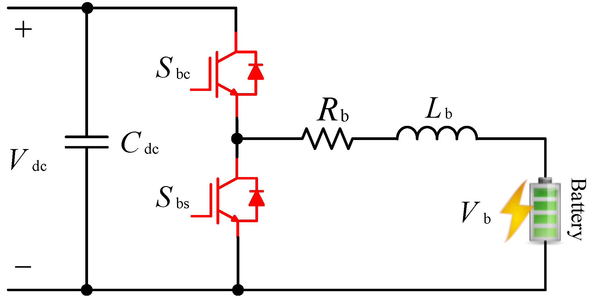
| Non-isolated | [26] | Figure 7 | 1-phase Buck | 2 switches | 250 V/48 kW | - | Simple structure and control/V2G support | Large inductor/Low power density/Limited power rating/Absence of isolation/No soft-switching |
| [77] | Figure 8a | 2-phase Interleaved Buck converter (IBC) | 2 switches 2 diodes | 150–200 V | Up to 96% | Reduced switching losses/Lower voltage stress on the semiconductor devices/Reduced current ripple/Compact structure/Better step-down voltage ratio | Sensitivity of current equalization among the phases to duty cycle fluctuation/Absence of isolation/No soft-switching/No V2G support | |
| [78] | Figure 8b | 3-phase Interleaved Buck converter (IBC) | 6 switches (each module) | 200–800 V/ Up to 150 kW | - | Increased power/Low cost simple design/Balanced power-sharing among the phases/Modularity/Low input and output current ripple/Minimized inductor size by operating in the discontinuous mode (DCM)/Soft-switching/V2G support | Different phase characteristics (such as power losses and RMS current) among the interleaved phases/Sensitivity of current equalization among the phases to duty cycle fluctuation/Soft-switching would be difficult at higher switching frequencies/Absence of isolation | |
| [82] | Figure 8c | 3-level asymmetrical voltage source converter | 4 switches | 200–500 V/40 kW | - | Lower rated switches/High-frequency operation/Smaller inductor/Reduced price and size/Compact structure/V2G support/Lower output and inductor current ripples | Absence of isolation/No soft-switching | |
| [84] | Figure 8d | Parallel 3-level buck converter | 8 switches | 1.2 kW | - | Can operate with a bipolar DC bus/Compact structure/V2G support | High voltage ripple at the input side/High circulating current/Absence of isolation/No soft-switching | |
| [126] | Figure 8e | Zero voltage transition (ZVT) converter | 4 switches | 220 V | - | High voltage conversion ratio/Compatible with different voltage ranges/Reduced voltage ripple with interleaved design/Soft-switching/V2G support | High conduction power losses because the resonant circuit is positioned in the current path)/Absence of isolation | |
| [127] | Figure 8f | Interleaved ZVT | 6 switches | 70–400 V/1 kW | ~95% | Low conduction losses/Low input current ripple/Small size inductors/Interleaved design/Soft-switching | High power losses at high power applications/Reverse recovery loss of body diodes/Absence of isolation/No V2G support | |
| [128] | Figure 8g | Half-bridge ZVT | 4 switches | 250 V/100 W | - | Capable of operating at moderate duty-cycle ratio/Lower EMI/Reduced voltage stresses on switches/Compact structure/Relatively simple control/Soft-switching/V2G support | Limited soft-switching range/Increased losses when operating at high switching frequencies/More components in the current path/Longer conduction path/Low efficiency/Absence of isolation | |
| [129] | Figure 8h | 3-level ZVT | 6 switches | ~300 V/100 kW | 98% | Reduced voltage stresses on semiconductor devices, so suitable for medium and very high-power applications/Soft-switching/V2G support | More resonant circuits/increased probability of losing soft-switching/High losses at light loads/Large size and the volume of the circuit/High control complexity | |
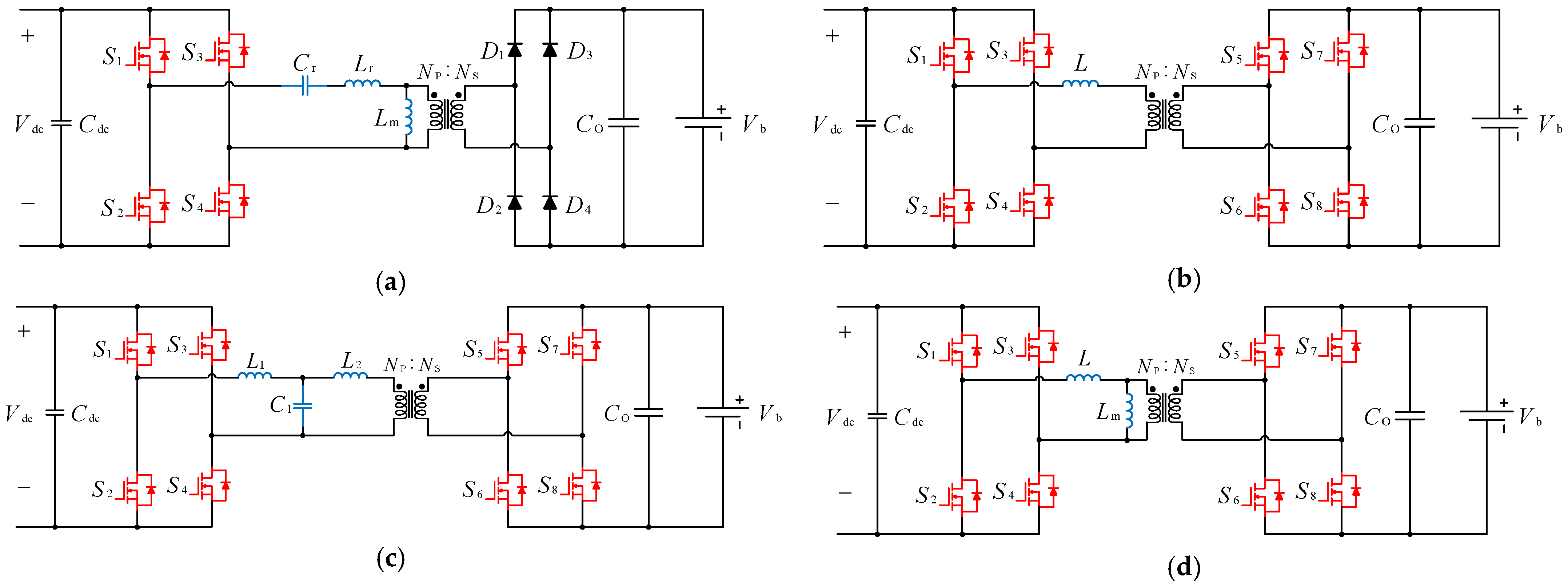
| Isolated | [121] | Figure 9a | Full-bridge 3-level LLC resonant converter | 6 switches 6 diodes | 225–378 V/6.6 kW | 98.14% | Good voltage regulation/Can operate with light loads/No diode recovery losses/A single capacitor to filter the output side/Compact size/Low EMI/High efficiency/Soft-switching | Unidirectional power flow/Complex design procedure/Switching and resonant frequencies are close/No V2G support |
| [57] | Figure 9b | Dual-active bridge (DAB) converter | 8 switches | 200–450 V/20 kW | 96% | High efficiency/High power density/Galvanic isolation/Soft-switching/V2G support/Modular design/Wide range of voltage transfer ratio | Soft-switching is challenging at light to medium EV battery voltage/Transformer peak current losses/Transformer’s operation in saturation/Current overshoot/High losses/High-frequency current ripple, reducing battery lifetime | |
| [63] | Figure 9c | Dual-active bridge (DAB) LCL resonant converter | 8 switches | 400 V/4 kW | 95% | Reduced reactive power/Increased efficiency/Reduced conduction loss compared to DAB converter/No transformer saturation/V2G support | Cannot guarantee soft-switching for a wide range of battery voltage/Complex synchronization and control/High cost | |
| [75] | Figure 9d | Phase-shifted full-bridge (PSFB) converter | 4 switches 6 diodes | 270–420 V/3.3 kW | 98.5% | Modular design/Reduced stresses on semiconductor devices/reduced Electro magnetic interference/No circulating current on primary and secondary sides/Soft-switching | Hard switching for secondary side diodes/Low efficiency/Severe voltage overshoot across the full-bridge rectifier due to high-voltage EV charging/Reverse recovery problems of the diodes for high power flow/No V2G support | |
| Type | Ref. | Figure | No. of S/D | Rectification/Inversion Mode | Voltage/Power | THD | η | Specifications | ||
|---|---|---|---|---|---|---|---|---|---|---|
| Advantages | Disadvantages | |||||||||
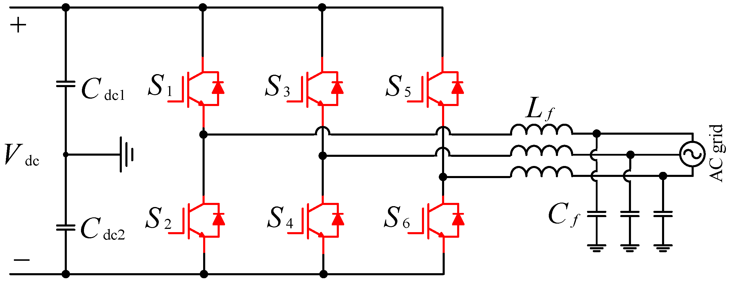
| Voltage source Inverter (VSI) | Step-up (Boost mode) | [45] | Figure 10 | 6 Switches | Both | 620 V/4 kW | 3.29% | 96.5% | Simplified structure and control scheme/Continuous input current/High output DC voltage/Low current stress/Low THD/High efficiency/Soft-switching | Harmonics appear at the DC-link voltage under unbalanced/AC input voltage/High switching losses |
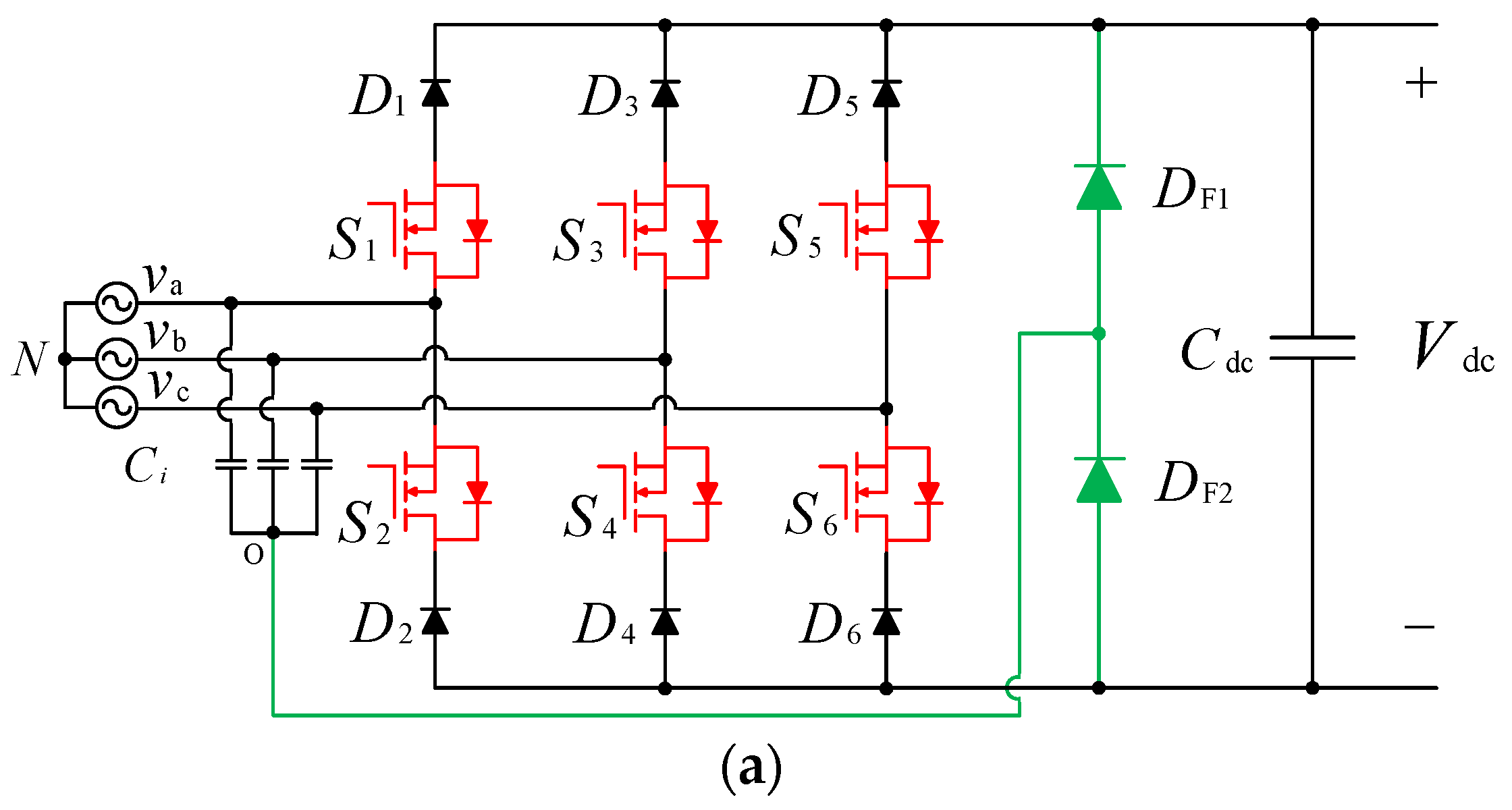
| Step-down (Buck mode) | [31] | Figure 11a | 6 Switches 8 diodes | Rectification | 600 V | - | ~97% | Simplified structure and control scheme/Continuous input current/High output DC voltage/Low current stress/Low THD/High efficiency/Minimized reverse recovery losses of the anti-parallel diodes/Soft-switching | Semiconductor losses/High voltage stresses on the switches in EV charging/Input current distortion, especially at light load conditions/Complex control/Reduced soft-switching capability | |
| VIENNA converter | [42] | Figure 11c | 12 Switches | Both | 800 V/15 kW | <5% | >98% | Suitable for high power applications/Simple structure and control method/High power Density and efficiency/Low THD/Neutral connection-free structure/Low voltage stresses on the switches/Consistent with bipolar DC bus/Soft-switching/operating at unity power factor | The need for dc-link capacitors/Limited switching frequency for a better trade-off between high efficiency and high-power density | |
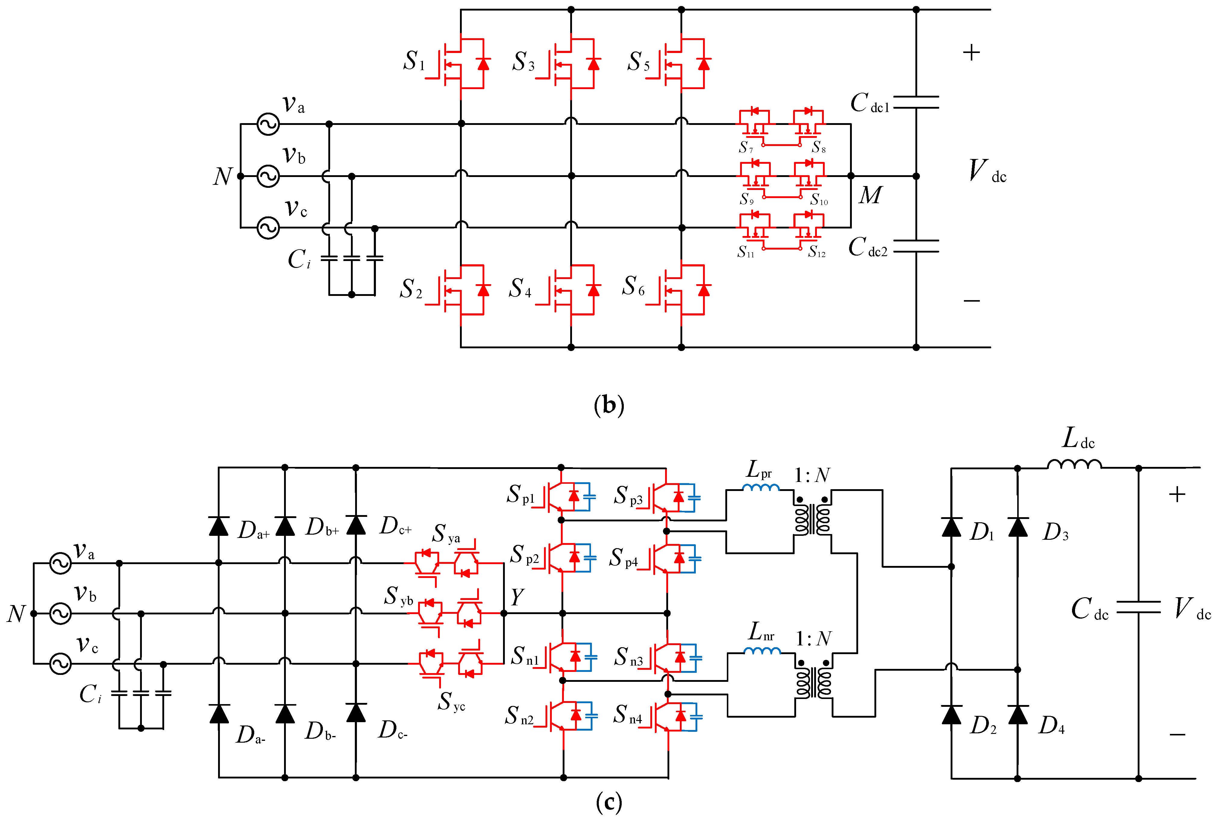
| SWISS converter | [39] | Figure 11b | 14 Switches 10 diodes | Rectification | 400 V/10 kW | <3% | 95% | High efficiency/Low common-mode noise/Low conduction and switching loss | Complex circuit and control in high power levels/Unidirectional power flow/Reduced soft-switching capability | |
| Multilevel | CHB | [46] | Figure 12a | 8 Switches (per phase) | Both | 540 V/2 kW | Low | 95.4 % | Several switching states/Modularity/Capability to isolate the faulty cells without any interruption in operations/Low current ripple/Robustness/Easy implementation | Capacitors voltage balancing/Inadequacy of delivering maximum modulation index/Vulnerability to potential failure/Reliability/No soft-switching |
| NPC | [51] | Figure 12b | 16 switches 8 diodes | Both | ~450 V/3.6 kW | 5.39% | - | Less distortion in output voltage waveforms/Decreased stresses on switches/Low THD/Minimised switching losses/Improved reliability/Consistent with bipolar DC bus structure | Severe unbalancing problem caused by uncertainties (e.g., various battery technologies and random arrival of vehicles/Limited switching frequency/Limited maximum phase current/Complex control/No soft-switching | |
| FC | [48] | Figure 12c | 8 switches (per level) | Both | 400 V/1.5 kW | <3.5% | ~99% | High-frequency operation/Smaller passive components/High power delivery capability (in three-phase) | High cost/Challenges in PFC/No soft-switching | |
| Ref. | Figure | Sub-Converters | Power Range | Operating Modes | η | Specifications | |||
|---|---|---|---|---|---|---|---|---|---|
| EV-Interfaced Converter | Grid-Interfaced Converter | PV-Interfaced Converter | Advantages | Disadvantages | |||||
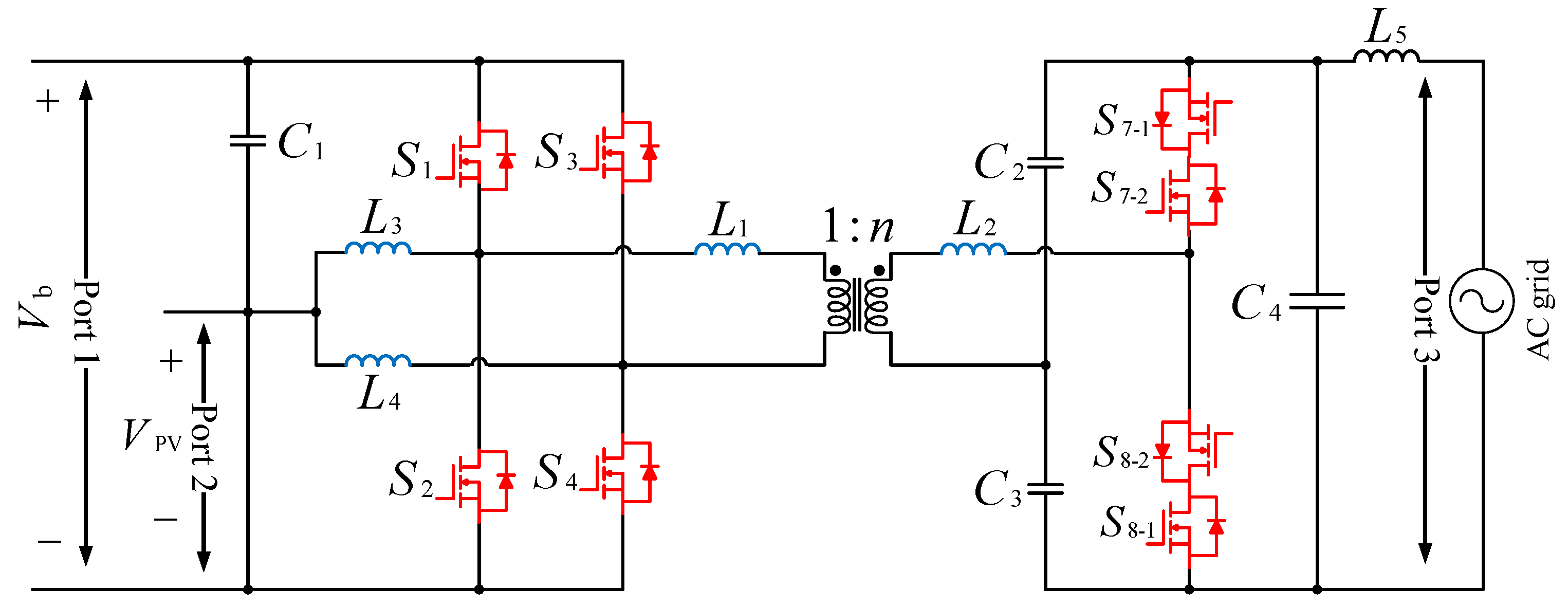
| [18] | Figure 13 | Interleaved Flyback | Three-phase VSI | Interleaved boost | 10 kW | V2G, PV2EV, PV2G, G2V | ~95% | High power density/Modularity/Electrical isolation/High Switching frequency/High partial and peak load efficiency | Hard switching for the interleaved PV-interfaced and three-phase VSI/Complex controls for the three sub-converters/Reliability concerns/No ESU/No control over SOC of the EV batteries/Soft-switching for EV-interfaced converter only |
| [86] | Figure 16 | Half-bridge | Full-bridge | Half-bridge | 3.5 kW | V2G, PV2EV, PV2G, G2V | - | V2G support/Low THD/Simple structure/High power density/Unity power factor | No ESU/No electrical isolation/Hard switching/No soft-switching |
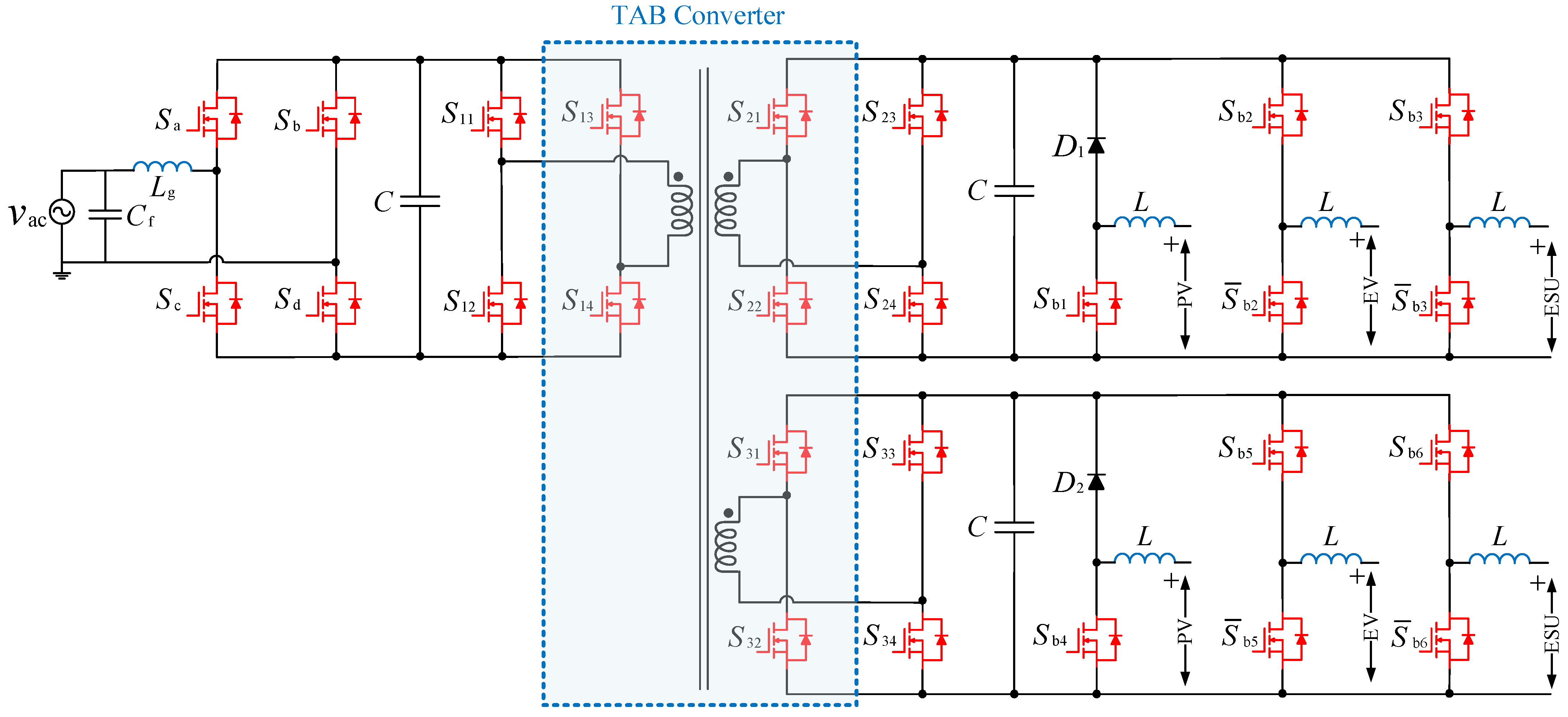
| [88] | Figure 14 | Bidirectional DC–DC converter | Bidirectional AC–DC converter | Unidirectional Boost | - | V2G, PV2EV, PV2G, G2V, PV2ESU, ESU2G, ESU2EV, G2ESU | - | Electrical isolation/Modularity/A wide variety of DC sources are supported through a multi winding transformer | Hard switching for the PV-, EV-, and grid-interfaced sub-converters, particularly in high power applications/Challenging transformer design for high power flow/Soft-switching for TAB converter only |
| [89] | Figure 15 | Interleaved Boost | Dual-active bridge (DAB) | Interleaved Boost | 0.2 kW | V2G, PV2EV, PV2G, G2V | ~96% | Simple and Compact design/No complex control or optimization for the modulation technique/High power density/It can be scaled up to high power levels | No ESU/Hard switching for the interleaved Boost converter/Large output filter is required to secure low THD/Soft-switching for DAB converter only |
Publisher’s Note: MDPI stays neutral with regard to jurisdictional claims in published maps and institutional affiliations. |
© 2022 by the authors. Licensee MDPI, Basel, Switzerland. This article is an open access article distributed under the terms and conditions of the Creative Commons Attribution (CC BY) license (https://creativecommons.org/licenses/by/4.0/).
Share and Cite
Nasr Esfahani, F.; Darwish, A.; Williams, B.W. Power Converter Topologies for Grid-Tied Solar Photovoltaic (PV) Powered Electric Vehicles (EVs)—A Comprehensive Review. Energies 2022, 15, 4648. https://doi.org/10.3390/en15134648
Nasr Esfahani F, Darwish A, Williams BW. Power Converter Topologies for Grid-Tied Solar Photovoltaic (PV) Powered Electric Vehicles (EVs)—A Comprehensive Review. Energies. 2022; 15(13):4648. https://doi.org/10.3390/en15134648
Chicago/Turabian StyleNasr Esfahani, Fatemeh, Ahmed Darwish, and Barry W. Williams. 2022. "Power Converter Topologies for Grid-Tied Solar Photovoltaic (PV) Powered Electric Vehicles (EVs)—A Comprehensive Review" Energies 15, no. 13: 4648. https://doi.org/10.3390/en15134648
APA StyleNasr Esfahani, F., Darwish, A., & Williams, B. W. (2022). Power Converter Topologies for Grid-Tied Solar Photovoltaic (PV) Powered Electric Vehicles (EVs)—A Comprehensive Review. Energies, 15(13), 4648. https://doi.org/10.3390/en15134648