Article

Experimental Study on Propagation Characteristics of Kerosene/Air RDE with Different Diameters

Science and Technology on Plasma Dynamics Laboratory, Air Force Engineering University, Xi’an 710038, China
*
Author to whom correspondence should be addressed.
Energies 2022, 15(12), 4442; https://doi.org/10.3390/en15124442
Submission received: 17 May 2022 / Revised: 11 June 2022 / Accepted: 15 June 2022 / Published: 18 June 2022

Abstract

:
A series of experimental tests were carried out in order to study the propagation characteristics of a liquid kerosene rotating detonation engine (RDE) with different diameters. Distinguished characteristics of spatial and temporal instability were found in the large-scale RDE due to the uneven circumferential distribution of kerosene supply pressure. As for the two counter-waves detonation system, the 500 mm-diameter RDE maintains a higher detonation wave velocity due to its longer injection recovery time. However, the 220 mm-diameter RDE can obtain a larger equivalence ratio operation range, higher specific thrust, and higher specific impulse. In addition, compared with the deflagration combustion, the detonation combustion has higher chamber pressure and thrust under the same operational conditions.

Graphical Abstract

1. Introduction

Detonation combustion has been widely studied in view of its potential benefits compared to existing combustors operating in a conventional deflagration mode [1]. Detonation provides a greater intensity of heat release and smaller entropy increase. The theoretical efficiency of the thermodynamic cycle based on detonation can be improved by nearly 20–50% when compared with the classical Brayton cycle [2]. Due to its higher working frequency and stable thrust output, continuous rotating detonation has a wide range of potential applications in the fields of aviation and aerospace power [3].
At present, most studies on RDE have mainly focused on gaseous fuels, such as hydrogen [4,5,6], acetylene [7,8], ethylene [9], and methane [10]. However, due to the volumetric efficiency of liquid storage [11] and higher energy density, liquid fuel is more attractive for practical applications. In recent years, significant progress has been made in the research and development of rotating detonation of macromolecular liquid fuels such as aviation kerosene, diesel, and gasoline. Usually, methods such as the addition of hydrogen or other highly active fuels, oxygen supplementation, oxidant heating, fuel heating, and fuel cracking are used to achieve kerosene rotating detonation.
For example, Le Naour et al. [12] used hydrogen mixing in kerosene to realize rotating detonation and found the problem of uneven propagation of the detonation wave caused by uneven distribution of two-phase fuel. In addition, the scheme of kerosene pre-heating evaporation has also been proposed, but with no follow-up report. Bykovskii et al. [13,14,15,16,17] successfully achieved kerosene/oxygen-enriched air (50% O2 and 50% N2) rotating detonation in a flow-type annular cylindrical combustor. They also obtained rotating detonation in a kerosene–air mixture with kerosene being bubbled with hydrogen or syngas, and found that the performance of the detonation engine changes significantly with the change in hydrogen concentration. Kindracki et al. [18,19] conducted research on the performance of a rotating detonation engine mixed with hydrogen and isopropyl nitrate in liquid kerosene and found that the addition of isopropyl nitrate enhanced the detonation sensitivity of kerosene, and a velocity deficit of 20–25% was determined for the mixture. Li et al. [20] carried out kerosene/hot air (100 °C) experiments with non-premixed and premixed strategies. Both methods can achieve rotating detonation. Studies have shown that the mixing and injection design of fuel and oxidants is critical to achieving detonation. Zheng et al. [21] carried out a rotating detonation experiment on hot air (620 K to 860 K) and kerosene fuels under supplemental oxygen conditions (oxygen mass fraction of 35%) and investigated the detonation propagation instability. Zhao et al. [22] have successfully achieved kerosene rotating detonation with oxygen-enriched air with an oxygen volume fraction of 40%; the stable rotating detonation waves can be obtained in a smaller combustor outlet. Ding et al. [23] also achieved kerosene rotating detonation with oxygen-enriched air. The effect of oxygen mass fraction (less than 40.5% to more than 43.6%) on wave propagation modes was investigated. Zhong [24,25] and Yang [26] used kerosene pre-combustion cracked gas and oxygen-enriched air (oxygen ratio of 50% and 30%) to achieve rotating detonation, and investigated the basic characteristics of the rotating detonation wave. Han et al. [27] also conducted experiments on rotating detonation with kerosene-fuel-rich gas and oxygen-enriched air and found that the minimum oxygen content that could successfully initiate and maintain the stable propagation of the detonation wave is 32%. According to these research results, it can be concluded that technical challenges still exist in liquid fuel rotating detonation due to the imperfect mixing of fuel and oxidant and the low chemical reaction activity of the fuel itself [21].
In recent years, attempts have also been made to combine RDE with gas turbines. For, example, Wolanski et al. [28,29] combined a kerosene–hydrogen rotating detonation combustor and a GTD-350 turbine to carry out detonation experiments and evaluated a 5–7% engine efficiency increase compared to the original engine. Frolov et al. [30] carried out an experiment combining a kerosene rotating detonation afterburner (CDA) with a TJ100 engine. Under the condition of supplemental oxygen (23% oxygen mass fraction), the specific thrust increased by 30% and the specific fuel consumption was reduced by 30% compared to the original afterburner. These results show that RDE has great potential in terms of engineering applications. However, when the air (could be from the compressor) is used as an oxidizer, a small combustor can be insufficient for obtaining rotating detonation with liquid fuels [31]. Furthermore, the application of RDE in a gas turbine also calls for a larger combustor structure when used to replace the main combustion chamber or afterburner. Wolanski et al. [32] have investigated the RDE performance with different diameters (100 mm, 150 mm, 200 mm), and found that a larger RDE can have a higher specific impulse. Bykovskii et al. [13,17] also conducted experiments on RDE with different diameters (306 mm, 503 mm) but did not compare their performance.
The use of jet fuels, for example aviation kerosene, in detonation-based engines is emerging as a promising possibility for the field of aviation [33]. Promoting the development of kerosene-fuel rotating detonation research, especially the research on engineering-level, large-scale rotating detonation combustion chambers, is useful for promoting RDE engineering applications. In this paper, the RP-3 kerosene rotating detonation is tested in a 500 mm-diameter large-scale RDE, and a 220 mm-diameter small-scale RDE is also investigated by contrast. The different detonation modes and propulsion performances of these two size RDEs are investigated, and the size effect is also concluded to better guide the large-scale RDE design.

2. Experimental Facility and Methodology

2.1. Experimental Facility

In order to explore the performance of different-sized rotating detonation engines, two kerosene/air continuous rotating detonation engines and a supporting experimental platform were built. The schematic diagram of the engine is shown in the Figure 1. The outer diameters of the detonation engines are 500 mm and 220 mm. The non-premixed injection strategy is utilized, in which the fuel and oxidizer enter the RDE channel through different flow passages. The fuel flows into the combustor radially through 180 (for 500 mm-diameter RDE) or 72 (for 220 mm-diameter RDE) equally spaced holes with a diameter of 0.2 mm under a high fuel injection pressure, while the oxidizer is fed into the annular channel through an axial convergence–expansion channel with a throat of 5 mm. The detailed geometry key parameters and operational conditions of the two engines are shown in Table 1. The temperature of the incoming air is about 500–520 K. The air is heated by an air–alcohol–oxygen three-component combustion air heater. The mass fraction of oxygen in the hot air is consistent with that in the atmosphere. A kerosene/oxygen hot jet is used for initiation. The hot jet generator is a small swirl combustion chamber. Kerosene and oxygen are ignited through a low-energy spark plug to form a high-temperature, high-pressure hot jet injected into the combustion chamber, igniting the rotating detonation wave.
A static pressure sensor and thermocouple are installed upstream of the throat to detect the incoming air pressure and temperature parameters. A static pressure sensor is installed in the detonation combustion chamber to monitor the pressure change in the combustion chamber under cold and hot conditions. In addition, three dynamic pressure transducers (PCB 113B24, PCB Piezotronics, Inc., New York, NY, USA) are installed 90 mm downstream of the air injection throat and circumferentially distributed along the outer cylinder wall of RDE with equal space. They are used to measure the peak of the detonation wave and to assist in estimating the propagation speed and mode of the detonation wave. Three combustion products’ collection interfaces (for 500 mm-diameter RDE) are fixed on the RDE outlet and in the middle position of the two PCB sensors in the circumference direction to collect combustion products. In the experiment, in order to prevent product pollution, a high-power diaphragm vacuum pump is used for gas extraction, a relay is used to control the solenoid valve to control the gas inlet timing, and the relay is programmed for timing control. Furthermore, the collected products are analyzed using an gas chromatograph (Agilent 7890b, Agilent Technologies, Santa Clara, CA, USA).

2.2. Time Sequence

This experiment adopts timing control. The experimental timing is shown in Figure 2. During the tests, the acquisition system is triggered to capture the high-frequency pressure oscillation in the combustor. Then, opening the air, after which alcohol and oxygen are injected into air heater simultaneously, the spark plug of the air heater is triggered before alcohol and oxygen. The kerosene solenoid valve is opened after the air heater begins working stably. Due to the large volume of the fuel chamber, a greater fuel plenum filling time should be given to ensure the stability of kerosene pressure. The ignition time of the hot jet is subject to the oxygen opening, which is maintained for about 0.3 s, and the whole detonation combustion working time is maintained for about 2.95 s for a 500 mm-diameter RDE (large-scale RDE) and 2.0 s for a 220 mm-diameter RDE (small-scale RDE). Furthermore, in order to ensure that the collected products are obtained during the self-sustaining detonation combustion period, the product collection time begins with the closing of the hot jet oxygen and ends with the closing of the kerosene supply.

3. Results and Discussion

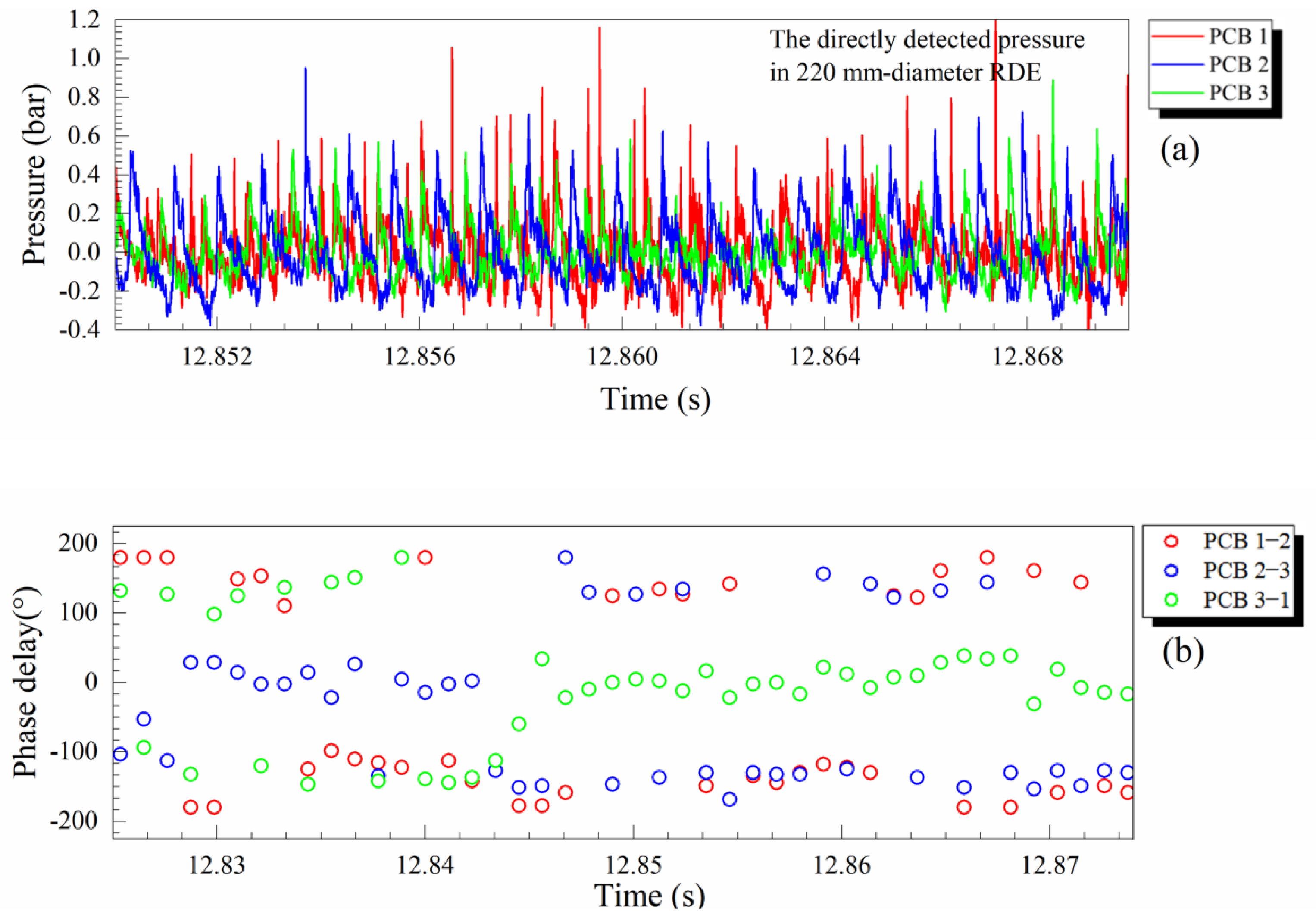
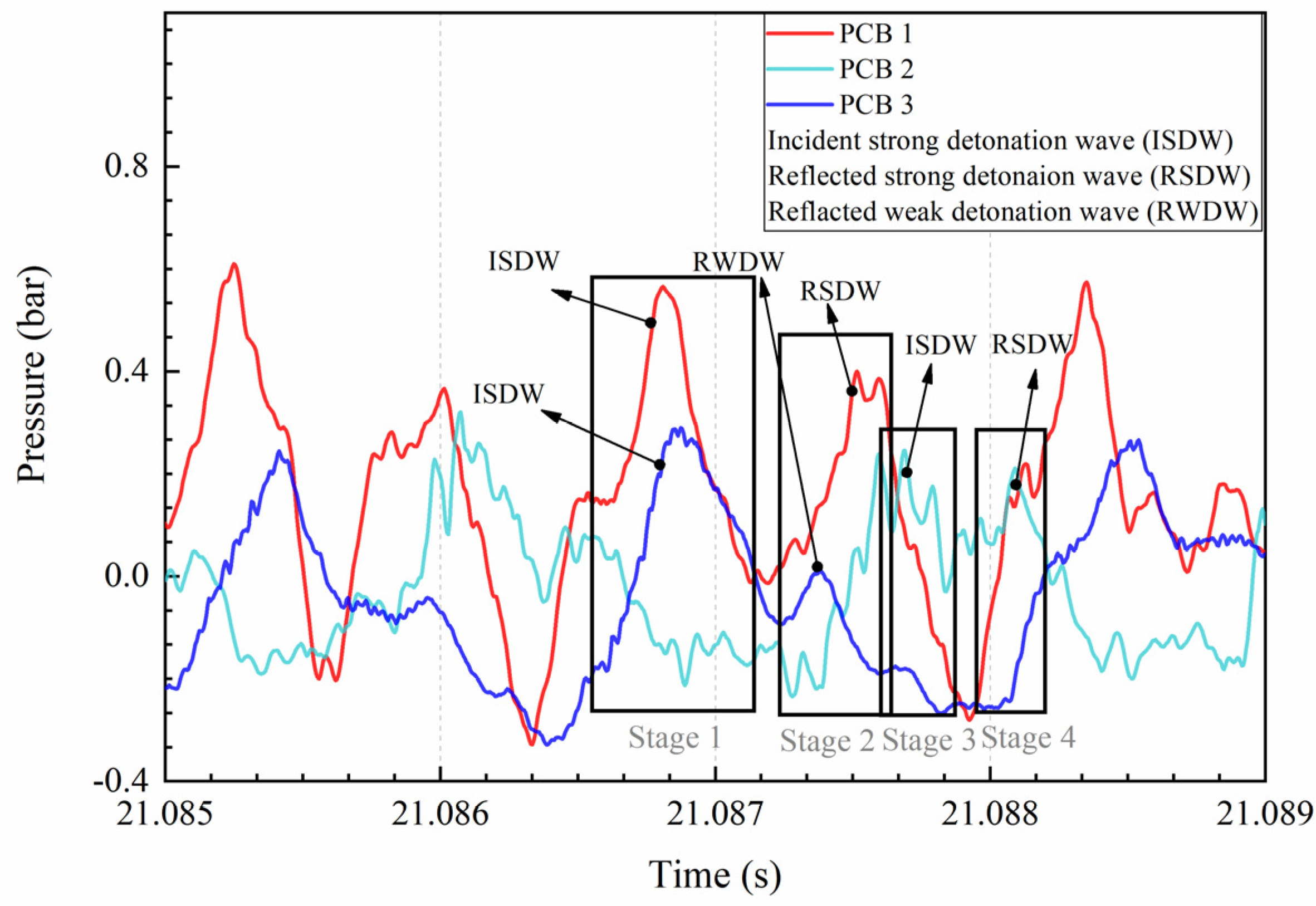
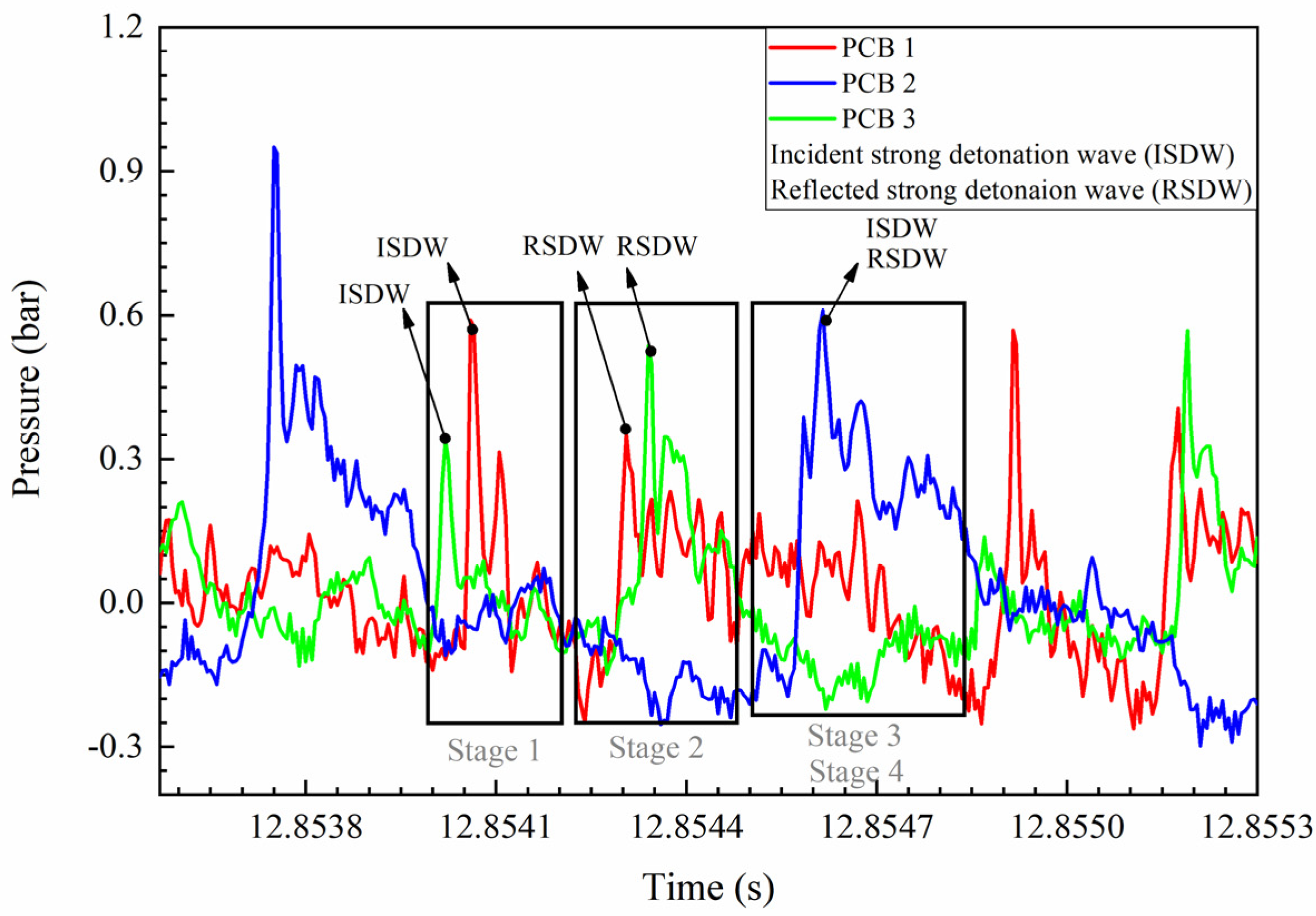
3.1. Analysis of Detonation Wave Propagation Mode and Spatial Instability

Due to the combustion products collection process, the 500 mm-diameter RDE has a longer operation time than the 220 mm-diameter RDE. Thus, the semi-infinite tube is used to measure the pressure in the large-scale RDE to avoid serious thermal ablation damage to the PCB sensors. Due to the pressure reflection and attenuation in the semi-infinite tube, some key information of the dynamic pressure signal may be lost. Therefore, there may be some distortion in amplitude and signal shape compared with the pressure signal collected by the PCB, which directly detects the detonation wave. However, it can still be used as an important basis for identifying modes and obtaining detonation wave velocity.
To identify the detonation wave propagating modes in the combustors with different diameters, a cross-correlation analysis [34] is used, by which the phase delay of the three pressure signals can be calculated. Figure 3a,b and Figure 4a,b demonstrate part of the typical pressure history diagrams and the typical cross-correlation results of the 500 mm-diameter RDE and the 220 mm-diameter RDE, respectively. In the experiment, the rotating detonation propagation mode is mainly that of non-stationary two waves’ collision. Two detonation waves propagate around the annular channel with opposite directions and collide twice in one cycle; the collision position always moves during the test.
However, there is a distinction in propagating modes between these two RDEs in terms of the detonation wave strength. Figure 5 and Figure 6 demonstrate the three PCB pressure signals’ local amplification of the 500 mm-diameter RDE and 220 mm-diameter RDE in detail, respectively. As can be seen in Figure 5, in the large-scale RDE, PCB 1 and PCB 3 can detect two strong incident detonation waves almost simultaneously, but only one strong reflected detonation wave can be detected by PCB1. The pressure strength detected by PCB 3 is too weak, and it cannot even be detected in some detonation cycles. Thus, it can be inferred that there is a strong and a weak detonation wave in this two-wave collision mode. When the departure detonation waves propagate through the annular channel after collision, one of them can transmit to a weak detonation wave or even decouple to a deflagration wave. However, the stronger ignition points could be generated under the reflection of the combustion chamber outer wall, and then the deflagration could be transformed into detonation combustion again [35]. It should be declared that the incident and reflected detonation waves here are relative to the collision point. Figure 7a–d shows the detonation waves’ propagation behavior in one cycle in the mode of one strong and one weak wave collision, which can be divided into four stages in total. They are the collision of two strong waves; the departure of one strong and one weak wave (during this period, the weak wave can be strengthened again in the process of propagation); the secondary collision of the two strong waves; and the reflection of the two waves, corresponding to the PCB signal changes in the four black solid line boxes in Figure 5 (stages 1–4, respectively).
Figure 6 demonstrates the typical pressure signal of the detonation-wave propagating cycle in small-scale RDE. The two pressure transducers (PCB 1 and PCB 3) could trace the arrival of two incident strong detonation waves almost simultaneously, as well as the departure of two strong reflected waves, which means that the collision point is in the middle position between these two PCBs. The third pressure transducer (PCB 2) then detects another collision event. Figure 7e–h describes the whole process of the two strong detonation waves colliding in one cycle in detail (corresponding to stages 1–4 in Figure 6).
In fact, through the mode analysis, it can be seen that there are differences in the spatial instability of the detonation-wave propagation mode in different sizes of RDEs. Through further research, it has been found that the inconsistency of two detonation waves’ intensity is largely due to the amplification of the uneven fuel pressure distribution for the large-scale RDE. Since the fuel supply ring is a one-way circuit, during the flow of kerosene along the fuel supply ring, the fuel injection holes on the inner wall of the fuel plenum are constantly unloading part of the pressure, resulting in pressure loss. At the same time, considering its own flow resistance loss, the fuel pressure is continuously reduced, and the fuel pressure is unevenly distributed along the circumference. With the increase in fuel pressure, the gap between the inlet and outlet fuel pressure will be further enlarged, resulting in an increase in the unevenness of the equivalence ratio distribution. Due to the size effect of the large-scale engine, this loss mechanism is amplified, which is rarely observed in the small-scale engine.
Two fuel pressure sensors were installed at the inlet and end of the fuel supply ring (for the 500 mm-diameter RDE), respectively. Figure 8 shows fuel pressure test data without ignition. It can be found that when the inlet gauge pressure is 1.045 bar, the end gauge pressure can only maintain 0.285 bar, which shows that even for a determined global equivalence ratio, the local equivalence ratio distribution along the circumference of the combustion chamber is not uniform. According to the different circumferential distribution of fuel flow, the annular combustion chamber can be roughly divided into three areas according to the distribution position of PCB, namely, the moderately fuel-rich area between sensors 3 and 1, the relatively fuel-rich area between sensors 1 and 2 and the slightly fuel-lean area between sensors 2 and 3. This also reveals the change in the detonation wave intensity in the 500 mm-diameter large-scale RDE. When the detonation wave departs after collision, the detonation wave in the fuel-lean area will be weakened or even decoupled, and the other will be restrengthened into a strong detonation wave after entering the fuel-rich area. In fact, most of the strong collision events happen in the moderately fuel-rich area and relatively fuel-rich area, corresponding to sensors 3–1 and 1–2, and the detonation waves are often weakened and even decoupled in the slightly lean fuel area between sensors 2 and 3.
To further illustrate the uneven distribution of detonation wave propagation along the circumferential direction, as introduced in the above section, three sampling points arranged along the circumferential direction are used to collect the combustion products and analyze their components (for 500 mm-diameter RDE).
Figure 9 is the signal peak intensity diagram of carbon dioxide, oxygen, and nitrogen components in the combustion product gas detected by gas chromatography. Since the air enters the combustion chamber evenly along the circumferential direction, the mass fraction distribution of carbon dioxide and oxygen at different positions can be converted using the principle of nitrogen invariance. It can be seen that as a combustion product, the concentration of carbon dioxide is higher in the so-called fuel-rich area and lower in the fuel-lean area. As an oxidant, the pattern of oxygen concentration is the opposite. This further confirms that the intensity of detonation combustion is stronger in fuel-rich areas and weaker in fuel-lean areas. Additionally, it demonstrates the continuous change in detonation wave intensity along the circumferential direction from another aspect.

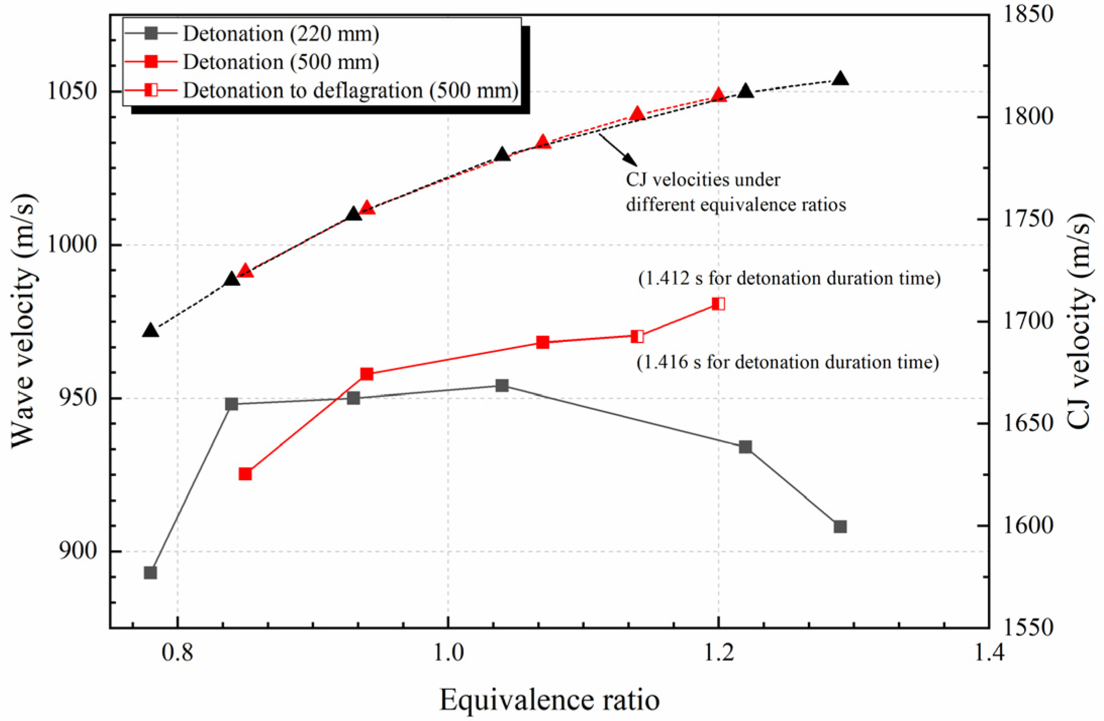
3.2. Analysis of Detonation Wave Propagation Velocity and Temporal Instability

The propagation velocities of detonation waves in combustors of different sizes are calculated from the pressure fluctuation detected by PCB. The variations in detonation wave velocity with equivalence ratio are shown in Figure 10. On the whole, the propagation velocity of the detonation wave in the 500 mm-diameter RDE is greater than in the 220 mm-diameter RDE under the same equivalence ratio condition. It is known that the propagation velocity of the detonation wave is closely related to the condition of fresh reactants immediately in front of the detonation wave [21]. Because the number of detonation waves in these two size RDEs is the same, a combustor with a larger diameter will have a longer injection recovery time and fuel–oxidant mixing time before the next detonation wave arrives. Taking the operating conditions near the stoichiometric equivalence ratio as an example; although the detonation wave velocity in the large-scale RDE reaches 969 m/s, the injection recovery time is still about 0.81 ms, while in the small-scale RDE, although the wave velocity is merely 954 m/s, the injection recovery time is only 0.36 ms. Therefore, in large-scale RDE, there will be a higher reactant-filling height and better mixing quality of the fresh mixture in front of the detonation wave, which will lead to a higher detonation wave velocity in the large-scale combustion chamber under the same equivalence ratio.
With the increase in equivalence ratio, the wave velocity in the large-scale RDE can still increase continuously, while in the small-scale RDE, the wave velocity first increases and then decreases with the increase in equivalence ratio, which can reach a maximum value near the stoichiometric equivalence ratio. In addition, the small-scale RDE can initiate detonation in a wider range of equivalence ratios, although the propagation velocity of the detonation wave decreases significantly when the operation condition is greater than the stoichiometric equivalence ratio. However, the detonation wave velocities for both size RDEs usually have 44–49% velocity deficit compared to the ideal CJ velocity for the kerosene/air mixture (as is shown in Figure 10), which echoes the weak detonation waves. Not only the imperfect mixing effect for heterogeneous fuel–air mixtures (FAMs), but also the poor physical and chemical properties of FAMs (low chemical reaction activity of liquid kerosene and 500–520 K air with 23% oxygen mass fraction, etc.) lead to the weak detonation pressure and relatively low detonation wave velocities.
What is more, under the fuel-rich condition, the large-scale RDE cannot always maintain good performance. When the operating equivalence ratio is beyond 1.1 or so, the combustor is often unable to maintain a stable detonation mode after working for a period of time; it turns into deflagration combustion. We call this phenomenon the temporal instability of detonation wave propagation. It is known that the propagation of detonation wave highly depends on the local conditions of fresh mixture immediately before the wave arrival. Since the phenomenon of detonation transmitting to deflagration often occurs under the operating conditions exceeding the stoichiometric equivalence ratio, the kerosene flowrate is too large, more kerosene evaporates and leaves the combustion chamber rather than participates in the combustion at this time, which could take away part of the heat. The detonation stability can deteriorate with time. In addition, the increase in fuel supply pressure aggravates the uneven circumferential distribution of kerosene, which leads to the increase of instability in the propagation of detonation wave along the annular combustion chamber. Thus, it is easy for detonation combustion to decouple into deflagration combustion. When detonation turns into deflagration, the RDE will continue to operate in deflagration mode at a relative fuel-rich condition.
Besides, these two stages of combustion modes (detonation mode and deflagration mode) can be easily distinguished by the macro-phenomenon. As shown in Figure 11, after initiation, the 500 mm-diameter RDE gradually stabilizes to the continuous rotating detonation mode, accompanied by a sharp sound and a blue white and short flame, which is not evenly distributed in the circumferential direction. The detonation wave lasts for about 1.4 s and then transforms to the rapid deflagration mode. At this time, the flame presents a blue-red color and a long length.
Under the same operating conditions and structural conditions, after detonation turns to deflagration combustion, the combustion chamber pressure and the RDE thrust will be significantly reduced. Figure 11 (under the condition of 2.56 kg/s air flow, 1.14 equivalence ratio) shows that, compared with the deflagration mode, the thrust oscillation amplitude under the detonation mode is large, and the average thrust under this working condition is nearly 42.4% higher than that under the deflagration mode. According to the thrust formula, the higher thrust in the detonation state is caused by higher average chamber pressure of the combustion chamber and higher exhaust speed of combustion products [32].
It should be noted that, in terms of thrust value, because there is no nozzle installed, a large amount of energy released by combustion is not converted into thrust. As a result, the thrusts of both detonation combustion and deflagration combustion are not very large.

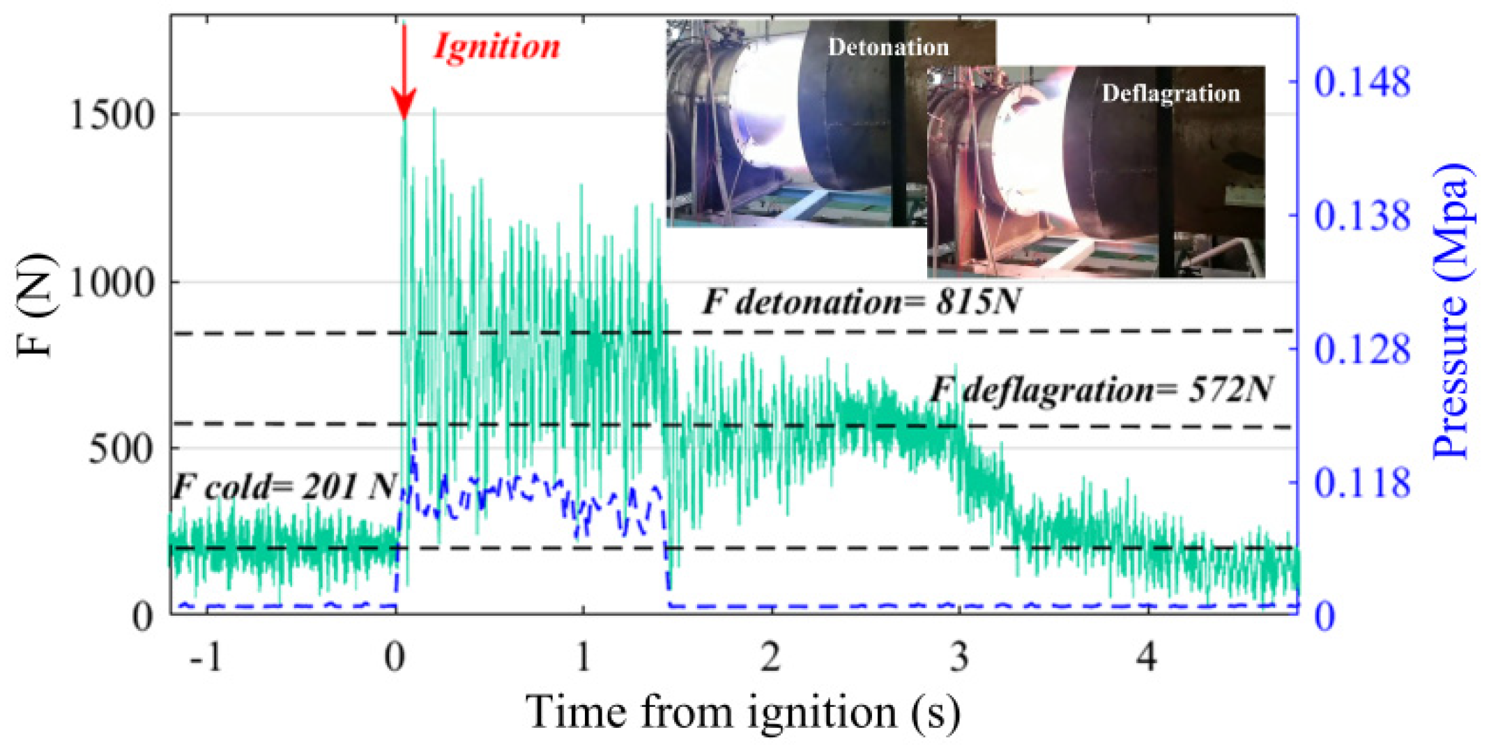
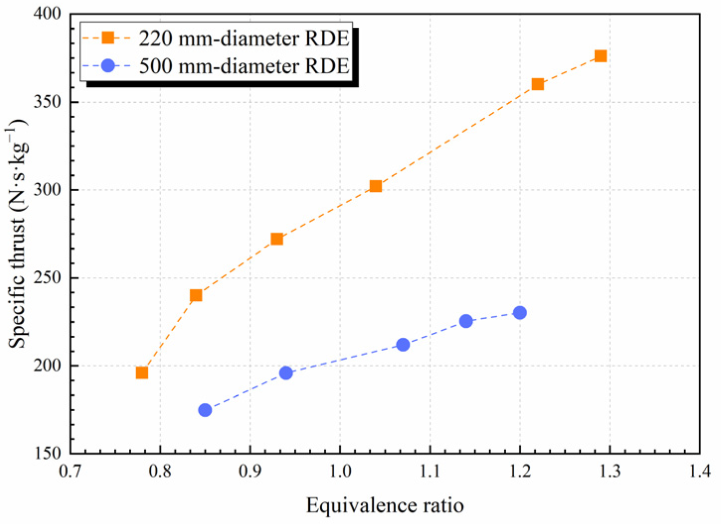
3.3. Comparative Analysis of Propulsion Performance of RDEs with Different Diameters

In order to explore the propulsion performance of RDE with different sizes, the specific thrust and specific impulse formulas are introduced to evaluate the oxidant utilization and fuel utilization of the RDE, respectively [36,37]. The formula of specific thrust is shown in Formula (1), and the specific impulse is obtained by Formula (2).
F s p = F h o t F c o l d m ˙ A i r
I s p = F h o t F c o l d m ˙ k e r o s e n e g 0
where, F h o t represents the stable average thrust of the engine under successful detonation, F c o l d represents the cold flow thrust of the engine before detonation ignition, m ˙ k e r o s e n e is the mass flowrate of kerosene injected in combustor, m ˙ A i r is the total hot air mass flowrate, and g 0 is the standard gravity. From the definition point of view, the above formulas can better synthetically characterize the thermal thrust performance and the fuel economy of the detonation combustor, respectively.
As shown in Figure 12, the specific thrust of both large- and small-scale engines increases with the increase in equivalence ratio. It is obvious that with the increase in injected fuel flowrate, the detonation wave velocity and the combustion chamber pressure increase, resulting in an increase in thrust. However, for the detonation engine with the same two counter-detonation waves system, the specific thrust performance of the large-scale engine is lower than that of the small-scale engine. Due to the limited effective thrust region generated by the detonation wave, for the large-scale engine, the detonation thrust region accounts for less annular area of the combustion chamber, and the airflow in more areas does not produce effective detonation thrust. In addition, due to the limitation of kerosene activity, when the mass flow flux is the same, although more injection recovery time promotes the detonation wave velocity and intensity, the thrust benefit still cannot compensate for the loss caused by the size amplification effect. Furthermore, as previously analyzed, the uneven distribution of the detonation wave along the circumferential direction (local strong detonation wave, local weak detonation wave or even deflagration) can also lead to a reduction in average specific thrust performance.
For the specific impulse, the same law is followed. With the enlargement of the engine size, the specific impulse decreases (as shown in Figure 13). It is well-known that the specific impulse is a measurement of fuel utilization, which is closely related to engine combustion performance. On the one hand, as analyzed above, too long of an injection recovery time leads to a large amount of fuel leaving the combustion chamber without complete combustion, resulting in reduced combustion efficiency. On the other hand, the uneven distribution of detonation combustion in the circumferential direction (local fuel-rich combustion or local fuel-lean combustion) is also an important reason for unsatisfactory combustion performance. Therefore, improving the uneven fuel distribution caused by large-scale effects and increasing the number and intensity of detonation waves are important aspects to be studied in the next step.

4. Conclusions

In this paper, the liquid kerosene was selected as fuel and the 500–520 K preheated air with 23% oxygen mass fraction was the oxidizer. The experimental tests of a 500 mm-diameter rotating detonation engine and a 220 mm-diameter rotating detonation engine were carried out to study the propagation characteristics of a liquid kerosene rotating detonation wave under different size engines. The results are concluded as follows:
(1)
In the large-scale RDE, the uneven detonation combustion along the annular combustor was discovered. Due to the uneven distribution of fuel supply pressure, there is a strong detonation wave and a weak detonation wave propagating in opposite direction, while in the small-scale RDE, there are two strong counter detonation waves with almost the same intensity.
(2)
Higher detonation wave velocity can be obtained in the large-scale RDE compared with that in small-scale RDE due to the longer reactant injection recovery time. However, the larger RDE usually has a smaller detonation range of equivalence ratio. Especially in the fuel-rich equivalence ratio, there often exists transition from detonation combustion to deflagration combustion.
(3)
Due to the limited effective thrust region generated by the detonation wave, a small-scale engine often has a higher specific thrust performance and higher specific impulse performance in the same two counter detonation waves system.
In view of fact that this paper does not achieve strong kerosene detonation wave compared to their ideal CJ velocities in both size RDEs, it is necessary to further improve the fuel–oxidant mixing strategy and combustor structure to promote the application of RDE fueled by kerosene.

Author Contributions

Data curation, J.Z.; Formal analysis, X.Y.; Investigation, P.C.; Writing—original draft, S.X.; Writing—review & editing, F.S. All authors have read and agreed to the published version of the manuscript.

Funding

This research was funded by National Natural Science Foundation of China, grant number 52106190.

Institutional Review Board Statement

Not applicable.

Informed Consent Statement

Not applicable.

Data Availability Statement

Not applicable.

Conflicts of Interest

The authors declare no conflict of interest.

References

  1. Frolov, S.M.; Aksenov, V.S.; Ivanov, V.S.; Shamshin, I.O. Large-scale hydrogen–air continuous detonation combustor. Int. J. Hydrogen Energy 2015, 40, 1616–1623. [Google Scholar] [CrossRef]
  2. Heiser, W.H.; Pratt, D.T. Thermodynamic cycle analysis of pulse detonation engines. J. Propuls. Power 2002, 18, 68–76. [Google Scholar] [CrossRef]
  3. Muraleetharan, K.; Polanka, M.D.; Schauer, F.R.; Huff, R. Detonation Confinement using a Flat Channel Plate in a Radial Rotating Detonation Engine. In Proceedings of the AIAA Scitech 2020 Forum, Orlando, FL, USA, 6–10 January 2020. [Google Scholar]
  4. Wang, Y.; Wang, J.; Li, Y.S.; Li, Y. Induction for multiple rotating detonation waves in the hydrogen—oxygen mixture with tangential flow. Int. J. Hydrogen Energy 2014, 39, 11792–11797. [Google Scholar] [CrossRef]
  5. Bykovskii, F.A.; Zhdan, S.A.; Vedernikov, E.F. Realization and modeling of continuous spin detonation of a hydrogen-oxygen mixture in flow-type combustors. 2. Combustors with expansion of the annular channel. Combust. Explos. Shock Waves 2009, 45, 716–728. [Google Scholar] [CrossRef]
  6. Anand, V.; St. George, A.; Driscoll, R.; Gutmark, E. Experimental investigation of H2-air mixtures in a rotating detonation combustor. In Proceedings of the Turbo Expo: Power for Land, Sea, and Air, Montreal, QC, Canada, 15–19 June 2015; American Society of Mechanical Engineers: New York, NY, USA, 2015; Volume 56697. [Google Scholar]
  7. Wu, Y.; Zheng, Q.; Weng, C. An experimental study on the detonation transmission behaviours in acetylene-oxygen-argon mixtures. Energy 2018, 143, 554–561. [Google Scholar] [CrossRef]
  8. Bykovskii, F.A.; Vedernikov, E.F. Continuous detonation of a subsonic flow of a propellant. Combust. Explos. Shock Waves 2003, 39, 323–334. [Google Scholar] [CrossRef]
  9. Anand, V.; George, A.S.; de Luzan, C.F.; Gutmark, E. Rotating detonation wave mechanics through ethylene-air mixtures in hollow combustors, and implications to high frequency combustion instabilities. Exp. Therm. Fluid Sci. 2018, 92, 314–325. [Google Scholar] [CrossRef]
  10. Lin, W.; Zhou, J.; Liu, S.; Lin, Z. An experimental study on CH4/O2 continuously rotating detonation wave in a hollow combustion chamber. Exp. Therm. Fluid Sci. 2015, 62, 122–130. [Google Scholar] [CrossRef]
  11. Humble, J.; Heister, S.D. Heterogeneous detonation physics as applied to high pressure rotating detonation engines. In Proceedings of the AIAA Scitech 2021 Forum, Online, 11–15 and 19–21 January 2021; p. 1027. [Google Scholar]
  12. Le Naour, B.; Falempin, F.H.; Coulon, K. MBDA R&T effort regarding continuous detonation wave engine for propulsion-status in 2016. In Proceedings of the 21st AIAA International Space Planes and Hypersonics Technologies Conference, Xiamen, China, 6–9 March 2017; p. 2325. [Google Scholar]
  13. Bykovskii, F.A.; Zhdan, S.A.; Vedernikov, E.F. Continuous spin detonation of fuel-air mixtures. Combust. Explos. Shock Waves 2006, 42, 463–471. [Google Scholar] [CrossRef]
  14. Bykovskii, F.A.; Zhdan, S.A.; Vedernikov, E.F. Continuous spin detonations. J. Propuls. Power 2006, 22, 1204–1216. [Google Scholar] [CrossRef]
  15. Bykovskii, F.A.; Zhdan, S.A.; Vedernikov, E.F. Initiation of detonation of fuel-air mixtures in a flow-type annular combustor. Combust. Explos. Shock Waves 2014, 50, 214–222. [Google Scholar] [CrossRef]
  16. Bykovskii, F.A.; Zhdan, S.A.; Vedernikov, E.F. Continuous spin detonation of a heterogeneous kerosene—Air mixture with addition of hydrogen. Combust. Explos. Shock Waves 2016, 52, 371–373. [Google Scholar] [CrossRef]
  17. Bykovskii, F.A.; Zhdan, S.A.; Vedernikov, E.F. Continuous detonation of the liquid kerosene—Air mixture with addition of hydrogen or syngas. Combust. Explos. Shock Waves 2019, 55, 589–598. [Google Scholar] [CrossRef]
  18. Kindracki, J. Experimental research on rotating detonation in liquid fuel–gaseous air mixtures. Aerosp. Sci. Technol. 2015, 43, 445–453. [Google Scholar] [CrossRef]
  19. Kindracki, J.; Wacko, K.; Woźniak, P.; Siatkowski, S.; Mężyk, Ł. Influence of Gaseous Hydrogen Addition on Initiation of Rotating Detonation in Liquid Fuel–Air Mixtures. Energies 2020, 13, 5101. [Google Scholar] [CrossRef]
  20. Li, J.M.; Chang, P.H.; Li, L.; Yang, Y.; Teo, C.J.; Khoo, B.C. Investigation of injection strategy for liquid-fuel rotating detonation engine. In Proceedings of the 2018 AIAA Aerospace Sciences Meeting, Kissimmee, FL, USA, 8–12 January 2018; p. 0403. [Google Scholar]
  21. Zheng, Q.; Meng, H.L.; Weng, C.S.; Wu, Y.W.; Feng, W.K.; Wu, M.L. Experimental research on the instability propagation characteristics of liquid kerosene rotating detonation wave. Def. Technol. 2020, 16, 1106–1115. [Google Scholar] [CrossRef]
  22. Zhao, M.; Wang, K.; Zhu, Y.; Wang, Z.; Yan, Y.; Wang, Y.; Fan, W. Effects of the exit convergent ratio on the propagation behavior of rotating detonations utilizing liquid kerosene. Acta Astronaut. 2022, 193, 35–43. [Google Scholar] [CrossRef]
  23. Ding, C.; Wu, Y.; Xu, G.; Xia, Y.; Li, Q.; Weng, C. Effects of the oxygen mass fraction on the wave propagation modes in a kerosene-fueled rotating detonation combustor. Acta Astronaut. 2022, 195, 204–214. [Google Scholar] [CrossRef]
  24. Zhong, Y.; Wu, Y.; Jin, D.; Chen, X.; Yang, X.; Wang, S. Investigation of rotating detonation fueled by the pre-combustion cracked kerosene. Aerosp. Sci. Technol. 2019, 95, 105480. [Google Scholar] [CrossRef]
  25. Zhong, Y.; Wu, Y.; Jin, D.; Chen, X.; Yang, X.; Wang, S. Effect of channel and oxidizer injection slot width on the rotating detonation fueled by pre-combustion cracked kerosene. Acta Astronaut. 2019, 165, 365–372. [Google Scholar] [CrossRef]
  26. Yang, X.; Wu, Y.; Zhong, Y.; Song, F.; Xu, S.; Jin, D.; Chen, X.; Wang, S.; Zhou, J. Investigation of rotating detonation fueled by pre-combustion cracked kerosene under different channel widths. Proc. Inst. Mech. Eng. Part G J. Aerosp. Eng. 2021, 235, 1023–1035. [Google Scholar] [CrossRef]
  27. Han, J.X.; Bai, Q.D.; Zhang, S.J.; Wang, F.; Weng, C.S. Experimental study on propagation characteristics of rotating detonation wave with kerosene fuel-rich gas. Def. Technol. 2022; in press. [Google Scholar] [CrossRef]
  28. Wolański, P. Application of the continuous rotating detonation to gas turbine. In Applied Mechanics and Materials; Trans Tech Publications Ltd.: Schwyz, Switzerland, 2015; Volume 782, pp. 3–12. [Google Scholar]
  29. Wolański, P.; Kalina, P.; Balicki, W.; Rowiński, A.; Perkowski, W.; Kawalec, M.; Łukasik, B. Development of gasturbine with detonation chamber. In Detonation Control for Propulsion; Springer: Cham, Switzerland, 2018; pp. 23–37. [Google Scholar]
  30. Frolov, S.M.; Ivanov, V.S.; Shamshin, I.O.; Aksenov, V.S.; Vovk, M.Y.; Marchukov, E.Y.; Mokrynskij, I.V. Kerosene-fueled turbojet afterburner operating on detonative combustion. In Proceedings of the International Workshop on Detonation for Propulsion, Christchurch, New Zealand, 2–6 August 2019. [Google Scholar]
  31. Bykovskii, F.A.; Zhdan, S.A. Current status of research of continuous detonation in fuel-air mixtures. Combust. Explos. Shock Waves 2015, 51, 21–35. [Google Scholar] [CrossRef]
  32. Wolanski, P. Influence of Sizing on Rotation Detonation Combustor Performance; Instytut Lotnictwa: Warszawa, Poland, 2019. [Google Scholar]
  33. Dahake, A.P.; Singh, A.V. A Comparative Study of Critical Detonation Parameters for Jet A and an Alcohol-to-Jet Synthetic Biofuel. In Proceedings of the AIAA SCITECH 2022 Forum, San Diego, CA, USA, 3–7 January 2022; p. 0819. [Google Scholar]
  34. St. George, A.C.; Anand, V.; Driscoll, R.B.; Gutmark, E.J. A correlation-based method to quantify the operating state in a rotating detonation combustor. In Proceedings of the 54th AIAA Aerospace Sciences Meeting, San Diego, CA, USA, 4–8 January 2016; p. 1402. [Google Scholar]
  35. Anand, V.; Gutmark, E. Types of low frequency instabilities in rotating detonation combustors. In Active Flow and Combustion Control 2018; Springer: Cham, Switzerland, 2019; pp. 197–213. [Google Scholar]
  36. Schwer, D.; Kailasanath, K. Numerical investigation of the physics of rotating-detonation-engines. Proc. Combust. Inst. 2011, 33, 2195–2202. [Google Scholar] [CrossRef]
  37. Liu, X.Y.; Luan, M.Y.; Chen, Y.L.; Wang, J.P. Propagation behavior of rotating detonation waves with premixed kerosene/air mixtures. Fuel 2021, 294, 120253. [Google Scholar] [CrossRef]
Figure 1. The schematic diagram of the engine.
Energies 15 04442 g001
Figure 2. The experimental timing.
Energies 15 04442 g002
Figure 3. (a) The typical pressure history diagram and (b) the typical cross-correlation result in 500 mm-diameter RDE.
Energies 15 04442 g003
Figure 4. (a) The typical pressure history diagram and (b) the typical cross-correlation result in 220 mm-diameter RDE.
Energies 15 04442 g004
Figure 5. PCB pressure signals’ local amplification of 500 mm-diameter RDE.
Energies 15 04442 g005
Figure 6. PCB pressure signals’ local amplification of 220 mm-diameter RDE.
Energies 15 04442 g006
Figure 7. The detonation wave propagating process in one cycle. (ad) for 500 mm-diameter RDE, (eh) for 220 mm-diameter RDE.
Energies 15 04442 g007
Figure 8. The pressure at inlet and outlet of the fuel supply ring.
Energies 15 04442 g008
Figure 9. The signal peak intensity diagram of O2, CO2, N2.
Energies 15 04442 g009
Figure 10. The propagation velocities of the detonation waves in combustors with different sizes.
Energies 15 04442 g010
Figure 11. The RDE performance of transition from detonation to deflagration (the green solid line represents the thrust; the black dotted line represents the average thrust under different combustion mode; the blue dotted line represents the combustor gauge pressure).
Energies 15 04442 g011
Figure 12. The specific thrust change with equivalence ratio in different-sized RDEs.
Energies 15 04442 g012
Figure 13. The specific impulse change with equivalence ratio in different-sized RDEs.
Energies 15 04442 g013
Table 1. The geometry key parameters and operation conditions of the two RDEs.
Outer
Diameter
Combustor
Length
Combustor Channel WidthThroat WidthNumber of
Injection Holes
Interval Distance of Injection HolesAir Flow RateMass Flux in
Combustor
500 mm300 mm40 mm5 mm1808.1117 mm2.56 kg/s44.31 kg/(s·m2)
220 mm300 mm40 mm5 mm728.0681 mm1 kg/s44.23 kg/(s·m2)
Publisher’s Note: MDPI stays neutral with regard to jurisdictional claims in published maps and institutional affiliations.

