1. Introduction
According to the IEC 61869-2, a current transformer is defined as a device that transforms the primary current to a proportional secondary current, in which the phase offset is equal to approximately zero [
1]. According to the IEC 61869-99, a low-power current transformer (LPIT) is specified as a transformer without rated output power, and an electronic current transformer is a low-power transformer where signal processing is implemented by active electronic components [
2]. Electronic current transformers (ECTs), compared with inductive current transformers (CTs), are characterized by being lightweight, small in volume, with easy digitization and proper isolation. Therefore, ECTs are some of the most popular devices used for signal digitization in intelligent substations [
3,
4,
5].
In [
6], the authors presented a method to determine the behavior of the current transformer during the transformation of high-frequency currents, based on digital signal processing, and using a measuring card with analogue two-digit converters. For sinusoidal currents in the frequency range of 50 Hz to 1 kHz, a comparison was made between the voltages from current shunts connected in the secondary windings of the tested and reference CTs, when they transform the same primary currents. In [
7], a simple calibration procedure was presented to test the phasor measurement unit (PMU) and LPIT. The procedure consisted of studies on steady-state conditions of the power grid and rated values of the input current, voltage, and frequency. In the presented work, the calibration procedures of LPITs and PMUs for non-sinusoidal operations were developed. In [
8], the authors presented a measuring system that allowed testing the accuracy of the DC voltage and current transducers up to 300 A and 6 kV, with frequencies up to 10 kHz. The system allowed performing tests recommended by EN 50463-2. Moreover, to characterize the transducers under real operating conditions, additional tests were performed using developed synthetic complex waveforms. The most popular technology used in ECTs is based on Hall effect sensors [
9,
10]. In [
11], the authors described a method to test the accuracy of ECTs equipped with both analog and digital outputs. This solution was based on the methodology presented in the standard IEC 61869-6 [
12]. In [
13], the authors proposed a measurement technique using Hall effect sensors, which were symmetrically placed on the conductor to measure the current. However, this solution suffered from a dc offset voltage of the Hall sensor and a thermal drift caused by the external temperature. These factors affected the accuracy of the HCT. In [
14], the authors’ solution enabled an evaluation of the extension of the accuracy class for the power quality measurements by the active and passive current transformers, notwithstanding the types of CTs. The developed methodology indicated the need for additional extensions of CT routine tests. The proposed evaluation criteria considered the nonlinearity of the magnetization characteristics of the inductive CT magnetic core, in which the accuracy of transformation decreased with the RMS value of the primary current.
The distortions of currents and voltages in the power grid have caused new requirements to be introduced to instrument transformers (regarding the transformation accuracies of distorted current and voltage waveforms). According to the standard IEC 61869-6 and the technical report IEC 61869-103, they only concern LPIT [
12,
15]. Moreover, the requirements for harmonic transformation accuracy have not been defined so far. However, standardized requirements and proposed measurement systems have already been described in scientific publications [
16,
17,
18,
19,
20,
21]. In [
16], the problems involving wideband transformation accuracy of inductive CT are described. The performed analysis consisted of the magnetic requirements used to properly design the inductive CT. The source of the accuracy deterioration for the transformation of the distorted current was discussed. The results indicated that the magnetic properties that ensure high transformation accuracy of harmonics are different than required in the transient state. The aim [
17] was to investigate the metrological and magnetic circuit performances of the inductive CT in the transformation of the sinusoidal currents, in the frequency range of 50 Hz to 20 kHz. In [
18], the authors presented a calibration circuit for the evaluation of CT accuracy with distorted waveforms. Moreover, the system implementation and characterization were shown. Often, to feed the measuring circuit, a power amplifier and an arbitrary generator (or calibrators) are used [
18,
19,
22,
23]. To obtain higher current values (more than about 30 A), it is possible to use a high-current transformer [
24]. The calibration procedure—without the necessity of the high current system—is the ampere-turn method [
25]. This solution can only be applied for window type CTs. It enables calibration for distorted currents in the frequency range of harmonics from 50 Hz to 5 kHz. Active low-power transformers may also be used for this purpose [
7,
14,
26,
27,
28]. In [
26], the authors presented a measurement system used to determine the accuracy of the inductive and low power voltage and current transformers. This solution uses a portable digital acquisition system with low-cost voltage and current acquisition boards. The online calibration of ECT was proposed in [
28]. The performed tests showed simplification of the calibration procedure, reducing its costs. The turns ratio correction is applied to most inductive CTs, ensuring a higher accuracy class without changing the magnetic core material type. Therefore, the values of the current error may have positive signs [
29]. The turns correction influences the equivalent magnetization curve in the load condition of the tested inductive CT. The developed method can determine the inductive CT turns ratio correction and its actual turns ratio.
The article presented a method to determine the values of the current error and phase displacement of electronic CTs during the transformation of the distorted current in the ampere-turn conditions. The additional winding (with the number of turns required to obtain the same values of the voltages on the current shunts) is connected to this winding and output circuit. The voltages between the current shunts in the additional primary winding and the output circuit of the tested ECT were compared. The differential voltages associated with the differential currents and the composite errors were measured. Moreover, self-generation of the lower-order higher harmonics to the secondary current of the ECT was considered. Regarding the concept of self-generation, in this paper, it is understood that the ECT introduces (to the secondary current) additional low-order higher harmonics, even if they are not present in the primary current. This causes a significant change in the obtained values of the current errors and phase displacement. We investigated the influence of the RMS value of the primary current and load of the ECT on the obtained values of the current error and phase displacement. To summarize the investigations presented in this paper, the main key points are detailed as follows:
Analysis of the self-generation of low-order higher harmonics.
Influences of nonlinearity (of the magnetization characteristics of the magnetic core) on values of the current error and phase displacement.
RMS value influences of the primary current and output load of the ECT on the wideband accuracy.
The frequency characteristics of the current error and phase displacement are non-linear, despite the presence of the operation amplifier and the Hall sensor in the output circuit.
Application of the differential voltage measurements between the current shunts connected in series in the primary and secondary windings of the tested ECT (to designate the wideband accuracy).
Utilization of the ampere-turn method, used before only for inductive CTs, to designate the wideband accuracy of the tested ECT.
The paper is organized into five sections; in
Section 1 and
Section 2, the background and state-of-the-art are presented. In
Section 3, the description of the tested ECT and the measuring circuit used are provided. In
Section 4, the results of the determined values of the current error and phase displacement in the tested frequency range are shown. The study findings and discussion of the results are presented in
Section 5.
2. Principle of Electronic CT Operation
Most mass-produced electronic CTs have implemented Hall sensors used to measure the magnetic field strength of the magnetic core. Therefore, the external supply of a direct current is necessary. Replacing conventional inductive CTs with electronic ones requires the necessity of rebuilding the topographies of power stations and adopting new requirements. Moreover, low values of the output signals of electric CTs also require the utilization of the stand-alone merging unit (SAMU) for digital measurements of voltages and currents. This device enables the conversion of analog signals from the current transformers and voltage transformers in the IEC 61850 sampled values.
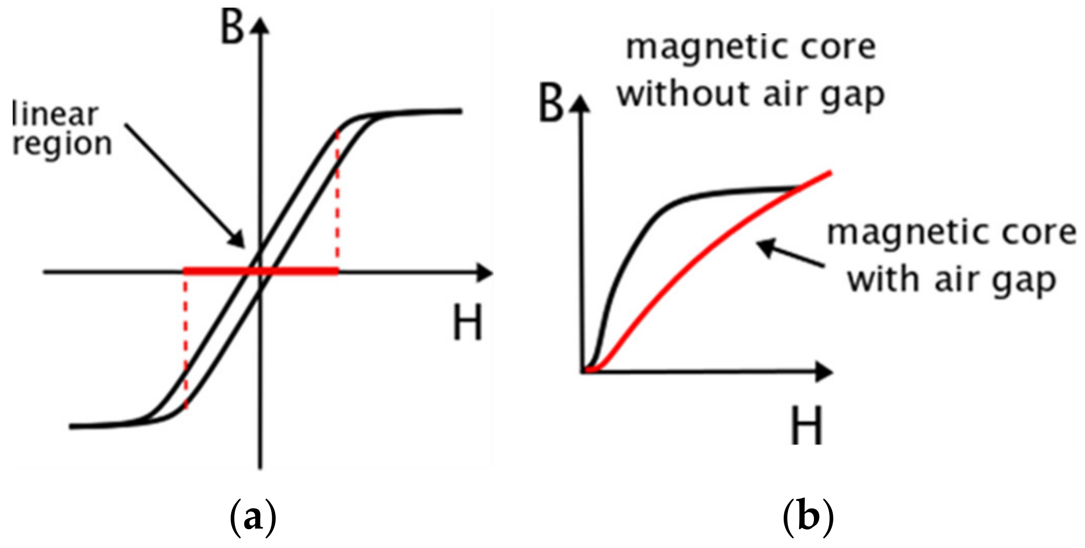
Electronic transformers using the Hall effect can be classified according to their feedback loop designs into open and closed loops. Open-loop transducers utilize the elemental application of the Hall effect. They ensure the most cost-effective solutions for current measurements with low power consumption, where the size and weight are reduced compared to the inductive CT. The primary winding of this transducer generates a magnetic field, which is concentrated by a magnetic core. The Hall sensor is used to detect the magnetic flux density and is placed in the air gap of the catted magnetic core. The differential gain and control current are provided by electronics in the transducer. If there is a linear relationship between magnetic flux density B and magnetic field strength H of the magnetic core, then the magnetic flux density B is proportional to the number of turns of the primary winding multiplied by the RMS value of the current flow in this winding. Moreover, regarding the magnetic flux density B, the Hall voltage is also proportional. Considering this and the Hall offset voltage, the instantaneous output voltage from the Hall sensor is proportional to the instantaneous value of the primary current. However, due to the nonlinearity of the magnetic core magnetization characteristics B–H, some deterioration of the transformation accuracy may occur. In
Figure 1b, the theoretical nonlinear magnetization curves are shown for the magnetic core with and without the air gap for the Hall sensor.
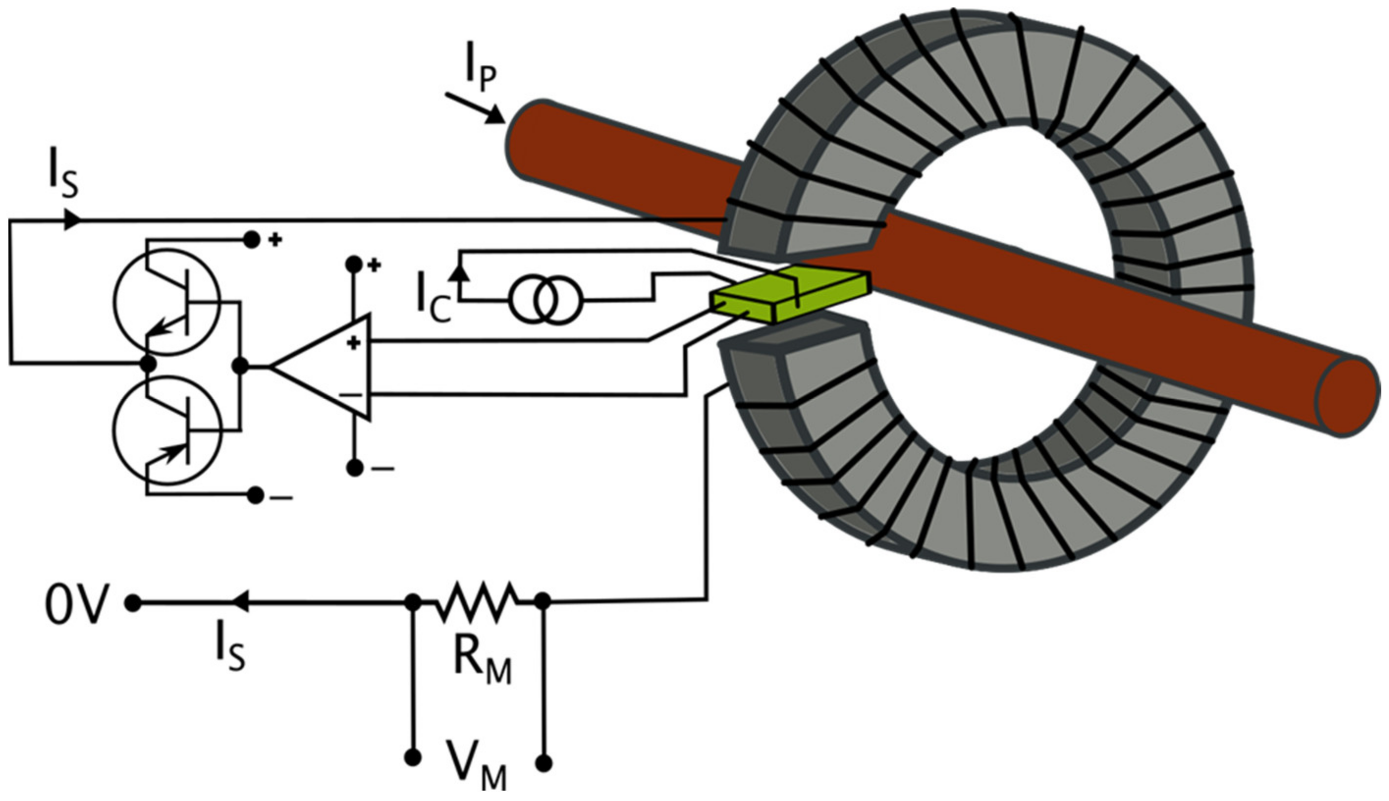
The measuring signal was thereafter compensated to eliminate the offset voltage and to counteract the temperature drift. After that, it was amplified to provide the required level of the output signal. The closed-loop Hall effect transducers (also known as zero flux transducers or Hall effect compensated transducers) were equipped with the compensating circuit that significantly improved the performance (
Figure 2). The secondary current, I
S, produced a flux equal to the flux produced by the primary current but in the reverse phase.
The zero flux operation eliminated the gain drift with the temperature. This approach enabled the utilization of the current transformer properties at higher frequencies. Therefore, the operation bandwidth significantly increased and the response time reduced. Full compensation of the magnetic flux density provided equal instantaneous values of the currents flowing in two windings. The secondary current ‘I
S’ is an accurate image of the measured primary current I
P. The current shunt R
M connected in series with the secondary winding provided an output voltage that was an accurate representation of the measured current. The typical number of turns of the secondary windings was in the range of 1000 to 5000, and the secondary current was usually in the range of 25 to 300 mA (although it could be (equal) up to 2 A). To achieve higher RMS values of the output currents, a higher gain of the amplifier was needed. The transducer operated at low frequencies using the Hall sensor. These effects are illustrated in
Figure 3.
The closed-loop transducer design ensured an operating frequency from DC to 200 kHz. The common problem of the transducers was to achieve a linear frequency response, in whole, considered spectrum, ensuring the proper intersection of the two operation curves. Moreover, regarding leakage flux, non-ideal coupling caused a residual flux in the magnetic core that resulted in a higher iron loss at an increased frequency. This may cause heating problems, but less significant than in the case of the open-loop-type transducer.
3. Measuring Circuit and Tested ECT
The tested electronic CT (ECT) was characterized by a 100 A/20 mA-rated current ratio and required an additional symmetrical DC power supply equal to ±12 V ± 15%. Moreover, the manufacturer specified the frequency range from DC to 100 kHz for any primary signal curves. The maximum load resistance of the current output was equal to 300 Ω. The accuracy was defined as ±0.5% without the specification of any IEC standard. The energy response time for 90% of the primary current (di/dt = 100 A/μs) was below 1 μs (the typical equals 150 ns). The accuracy tests of the window type CT can be done with the utilization of the reference CT or the ampere-turn method. To obtain equality of primary and secondary ampere-turns, the additional primary windings have to be wound. Therefore, for this tested ECT, the number of turns should be equal to 500 as it results from the rated current ratio. This approach enables the utilization of the differential current measurements, with the difference between the instantaneous current in the additional primary winding and the instantaneous output current. Another approach is to wind fewer turns of the additional winding and correctly select the values of the resistance of the used current shunts connected to the secondary and additional primary windings. The current shunts should have the same rated value of voltage during the normal operation of the tested ECT. Therefore, the differences between voltages on current shunts correspond to the differential currents. This enables determining the current error and phase displacement of the tested ECT. The presented approach is used in the measurement circuit in
Figure 4.
In
Figure 4, the following abbreviations are used:
AWG—arbitrary waveform generator;
DPM—digital power meter;
ECT—tested electronic CT;
iM—instantaneous value of the output current;
ip—instantaneous value of the current in the additional primary winding;
IT—isolation transformer;
PA—power amplifier;
PS—DC power supply;
RM—current shunt used to measure the output value of distorted current of the tested CT;
RP—current shunt used to measure the value of the distorted current in the additional primary winding of the tested ECT;
V1/V2—the voltage inputs of the measuring module of the DPM.
The measuring system is supplied by the power amplifier (PA) controlled by the arbitrary waveform generator (AWG). This allows to smoothly adjust the RMS values of the higher harmonics and their phase angles. The insulation transformers are used to ensure galvanic separation of the power amplifier and supplied circuit. Moreover, the ground potential level of a selected terminal can be forced. In the measuring circuit, the tested ECT has additional primary windings with 50 turns. The rated primary current of this winding is equal to 2 A. The resistance of the current shunt R
P is equal to 1 Ω, while the resistance of the current shunt R
M is equal to 100 Ω, where the rated output current is 20 mA. The rated voltage of both shunts equals 2 V. The differential voltage is measured between both shunts using differential channels of the DPM. Moreover, to determine current errors and phase displacements of the tested CT, the measurement of the voltage on the current shunt R
P is required. Therefore, considering the resistance of the used current shunts, the composite error can be determined from the equation:
where:
UDhk—the rms value of the
hk harmonic of the differential voltage between
RM and
RP current shunts,
UPhk—the rms value of the
hk harmonic of the voltage on the
RP current shunt.
Considering the phase angle between the measured
hk harmonic of both voltages, the rms value of the
hk harmonic of the secondary current can be determined from the equation:
where:
φhk—phase angle between the
hk harmonic of two measured voltages.
Therefore, the percentage value of the current error of the tested ECT for each hk higher harmonic of the distorted current can be determined from the equation:
The
hk values of the composite and the current errors allow determining the phase error of the tested ECT for each
hk higher harmonic of the distorted current:
The laboratory studies were performed during the transformation by the tested ECT on the distorted current, containing the main and single higher harmonics in the frequency range of 50 Hz to 5 kHz. Moreover, to designate the value of the self-generated higher harmonics of the tested ECT, the phase angles of the third and fifth higher harmonics, in relation to the main component, were adjusted by 10° steps, from 0° to 360°. The ECT was tested for 5%, 20%, 100%, and 120% of the main component of the rated primary current. The distorted current had a 10% level of the higher harmonic component. Additionally, the accuracy tests were conducted for two different loads of the output of the tested ECT, equal to 100 Ω and 300 Ω. This procedure enabled determining the values of the current error and phase displacement and investigated the influence of the load on the frequency characteristics of the ECT.
4. Results
The wideband transformation accuracy tests of ECT were performed in the measuring system from
Figure 4, using the rated ampere-turn method. In the first stage of the laboratory studies, the ECT was tested with an output load equal to 100 Ω. The results are presented in
Figure 5. For the third and fifth harmonics, their phase angles (in relation to the main component) were adjusted by 10° steps, from 0° to 360°. This approach was used to determine the influence of the self-generation phenomenon on values of the current error and phase displacement. In the presented figures, the characteristics labeled with (+) are determined for the highest positive values of the current error and phase displacement, while the characteristics labeled with (−) are determined for the highest negative values of the current error and phase displacement.
The change of the phase angle of the third and fifth higher harmonics led to different values of the current error and phase displacement between the highest positive and negative values. Due to this, the accuracy testes of the ECTs should be performed considering the self-generation phenomenon of the low order harmonics. The presented results indicate the change in the primary current RMS value caused by the change in the operation point of the magnetization curve of the magnetic core (
Figure 1b). The utilization of the Hall sensor due to nonlinearity of the magnetization characteristic of the magnetic core did not ensure the same operation point of the ECT. Due to this, the change in the values of the current error and phase displacement occurred with the RMS value of the primary current. The increase in the higher harmonic frequency to 5 kHz caused no significant changes in the wideband transformation accuracy.
In
Figure 6, we present the frequency characteristics of the current error and phase displacement values of the tested ECT for the resistive load equal to 300 Ω.
The increase in the output load of the ECT caused the increase of the Is current (
Figure 2) and an increase in the values of the current error. Moreover, the self-generation of the low-order higher harmonics also increased. These changes resulted from the increase of the magnetizing flux in the magnetic core of the ECT. This caused movement of the ECT operating point on the magnetization characteristic (
Figure 1b), closer to saturation, where nonlinearity is higher. This behavior is similar to what is widely used in power grid inductive CTs [
21]. To present a clearer self-generation phenomenon of the ECT, the percentage values of the third and fifth low-order higher harmonics are presented in
Figure 7. The calculations were performed according to the method presented in [
30].
Similar to the inductive CTs, the increase of the output load for the same value of the primary current caused an increase in the self-generation of the third and fifth low-order higher harmonics. Moreover, the increase in the primary current RMS value also caused an increase in the self-generation of these harmonics.


