Article

Transient Pressure and Rate Behavior of a Vertically Refractured Well in a Shale Gas Reservoir

1
School of Petroleum Engineering, Changzhou University, Changzhou 213164, China
2
Research Institute of Petroleum Exploration and Development of CNPC, Beijing 100089, China
*
Author to whom correspondence should be addressed.
Energies 2022, 15(12), 4345; https://doi.org/10.3390/en15124345
Submission received: 17 May 2022 / Revised: 11 June 2022 / Accepted: 13 June 2022 / Published: 14 June 2022
(This article belongs to the Section H1: Petroleum Engineering)

Abstract

:
Refracturing treatment is widely used to enhance the well productivity in shale gas reservoirs, particularly for initially fractured wells with low productivity. The principal of this work is based on the transient behavior of pressure and rate for a vertically refractured well in a shale gas reservoir, considering the fracture reorientation and adsorption and desorption property. Based on the point-source theory and Laplace transform, a semi-analytical solution for a refractured well is obtained by coupling the point-source solution of a shale gas reservoir and the solution of artificial fractures. The validation of this new solution is carried out smoothly by comparison with the results from the commercial software COMSOL. Five typical flow regimes are identified on the transient pressure curve, namely bi-linear flow regime, formation linear flow regime, mid-radial flow regime, inter-porosity flow regime, and pseudo-radial flow regime. A groove segment occurs on the transient-pressure derivative curve, and its width and depth largely depend on the adsorption and desorption constant and storativity ratio. Due to fracture reorientation, bi-linear flow regime, formation linear flow regime, and mid-radial flow regime may be significantly impacted. In addition, the transient rate of the refractured well in a shale gas reservoir is positively proportional to the storativity ratio, inter-porosity coefficient, and adsorption and desorption constant, while it is inversely proportional to fracture reorientation. These results provide important references for parameter design, property inversion, and productivity prediction of refracturing treatment in shale gas reservoirs.

1. Introduction

During the downturn of the oil and gas industry, refracturing treatment has become widely used and adopted for the economy of it enhancing low-productivity wells, which have undergone a fracturing stimulation, rather than drilling a new well in unconventional reservoirs, such as shale gas reservoirs [1,2,3]. Generally, refracturing treatment changes the flow state in the initial hydraulic fractures and also creates new fractures with complex morphologies. Under these circumstances, the low-productivity wells can be reactivated at a low cost [4,5,6,7]. Hence, accurately analyzing the transient pressure and rate behavior of refractured wells in shale gas reservoirs becomes necessary for understanding and predicting these wells’ dynamic production [8].
The transient pressure and rate behavior of fractured vertical wells or fractured horizontal wells in shale gas reservoirs have been extensively studied by many researchers. As the most representative results of the related studies, several semi-analytical and numerical models have been successively presented for investigating the transient behavior of the pressure or rate of fractured wells in shale gas reservoirs [9,10,11,12,13,14,15,16,17,18]. Considering the properties of desorption, Knudsen diffusion, and slip flow, Huang et al. [19] presented a semi-analytical model to simulate the transient pressure of a fractured vertical well in a shale gas reservoir. Chen et al. [20] employed the nodal analysis method to simulate the transient pressure behavior of a vertically fractured well with complex fracture networks. Later, Zhang et al. [21] proposed an elliptical stimulated reservoir volume (SRV) model to analyze the pressure and rate performance of a fractured well in a shale reservoir. However, the previous studies neglected the effect of complex fracture geometry on the well production in shale gas reservoirs. Using a finite element and finite difference to deal with the complex fractures, Zhang et al. [22] simulated the production performance of a multiple fracture horizontal well in a shale gas reservoir. Recently, Cui et al. [23] obtained a semi-analytical solution for the transient pressure and rate of a multiple fracture horizontal well in a shale gas reservoir by considering the effect of a space variable and stress sensitivity on hydraulic fractures. In order to predict shale gas productivity more accurately, Lin et al. [24] proposed a semi-analytical fractured horizontal well model in shale gas reservoirs by taking into account the effect of complex fracture morphology. Overall, the pressure and rate transient behavior of a fractured vertical well or a fractured horizontal well in a shale gas reservoir have been investigated widely.
Microseismic fracture monitoring shows that refracturing treatment can change the stress distribution near wellbore and create some complex fracture morphology, such as reorientation fractures [25,26,27]. Li et al. [28] established a coupled poromechanical model to define stress redistribution during the refracturing treatment of shale gas reservoirs. Based on this model, they demonstrated that the secondary refracture extends perpendicular to the initial hydro fracture and, ultimately, turns parallel to the initial hydro fracture due to stress redistribution during refracturing treatment. This viewpoint provides a guideline for the establishment of the mathematical model in this work. Teng and Li [29] introduced a semi-analytical model to characterize the transient flow behavior of a secondary refracture in the vicinity of the initial hydraulic fractures. However, their fracture model is based on the assumption of planar fractures, which are different from the actual non-coplanar fracture system, such as reorientation fractures. To simulate the transient flow behavior of a reorientation fracture, Wu et al. [30] employed the nodal analysis method to obtain a semi-analytical reorientation fracture solution in an anisotropic reservoir. By extending Wu et al.’s solution, several representative studies on the pressure and rate behavior of the vertically refractured wells in a conventional reservoir have been reported [31,32,33]. However, few researchers have studied the transient pressure and rate behavior of a refractured well in a shale gas reservoir.
To analyze the transient pressure and rate of a vertically refractured well in a shale gas reservoir with adsorption and desorption, a semi-analytical model is developed and validated in this work. Firstly, by coupling the semi-analytical solution for a shale gas reservoir and the analytical solution for an artificial fracture system (including a hydro fracture formed by initial fracturing and a reorientation fracture generated by refracturing), a semi-analytical solution for a vertically refractured well in a shale gas reservoir was achieved. Secondly, the validation of this model is carried out by comparing the proposed solution in this work with the results obtained from the commercial software (COMSOL). Thirdly, based on our solution, flow regime identification for this refractured well model in a shale gas reservoir is conducted. Finally, the influence of some key parameters on the transient pressure and rate is analyzed and discussed in detail. The relevant results in this work can provide an important reference and basis for parameter design, property inversion, and productivity prediction of refracturing treatment. This study also provides a new idea for researching more complex fracture networks in a similar stimulation process.

2. Physical Model

In this section, a physical model is established to analyze the transient pressure and rate behavior of a refractured well in a shale gas reservoir, as shown in Figure 1. For some initially fractured wells, the proppants inside the initial hydro fractures are embedded due to the consecutive withdrawal of shale gas, resulting in the current low production. In order to enhance the production of these fractured wells in shale gas reservoirs, refracturing treatment is a potential and available stimulation technology because of its low investment. Through refracturing treatment, the initial hydro fractures can be unplugged and restore their conductivities. Meanwhile, reorientation fractures are often generated after refracturing treatment due to the change in the stress field near the initial hydraulic fractures and the continuous extraction of shale gas. Some basic assumptions for this model are made as follows:
(1)
This shale gas reservoir is homogenous, infinite, and has a uniform initial pressure distribution. Refracturing treatment forms an artificial fracture system near the vertical wellbore, including a hydro fracture formed by initial fracturing and a reorientation fracture created by refracturing.
(2)
This fracture system penetrates the whole reservoir vertically, and its height is equal to the thickness of this shale gas reservoir, h. Each fracture has two symmetrical wings. The reorientation fracture consists of five parts: the principal fracture part with a length of (Rf1 + Rf3), which is perpendicular to the initial hydro fracture; two reoriented fracture parts with length Rf2 and Rf4, respectively, which are parallel to the extension of the initial hydro fracture; and two reoriented zones.
(3)
A pure gas flow is assumed to occur in the shale gas reservoir and artificial fracture system. The initial fracture and reorientation fracture have an equal conductivity after refracturing treatment.
(4)
Gas diffusion flowing out from the shale matrix observes Fick’s law, and gas flowing into natural fractures and artificial fractures obeys Darcy’s law. Also, the effects of gravity’s force are ignored.

3. Mathematical Models

3.1. Flow Model for Shale Gas Reservoir

Based on the above model assumptions and the dimensionless definitions in Appendix A, the point source pseudo pressure solution (Appendix B) of a shale gas reservoir with consideration of the mechanism of adsorption and desorption can be yielded in the Laplace domain:
m ˜ D ( x D , y D , s ) = q ˜ D i ( s ) τ K 0 [ s f ( s ) ( x D x w D ) 2 + ( y D y w D ) 2 ] d τ
where
f ( s ) = ω λ + ( 1 ω ) ( ψ λ + ω s ) ( 1 ω ) s + λ
In Equation (2), ω represents the dimensionless storativity ratio between the natural fracture system and shale matrix system; λ represents the dimensionless inter-porosity coefficient to describe the gas flow from the shale matrix to the natural fractures; and ψ represents the dimensionless adsorption and desorption constant to characterize the shale gas’s adsorption and desorption capacity.
A hydraulic fracture can be divided into a finite number of line sources with finite length. The solution of one line source can be obtained by integrating the solution of the point source according to the line-source theory. Based on this discrete integral idea and Equation (1), the line source solution (parallel to the x-axis) of a shale gas reservoir can be obtained as follows:
m ˜ D ( x D , y D , s ) = q ˜ D i ( s ) τ K 0 [ s f ( s ) ( x D x w D ) 2 + ( y D y w D ) 2 ] d τ
However, in this work, an arbitrary azimuthal angle, θi, exists between the line source and the x-axis—particularly for the reorientation fracture (Figure 1)—and thus a Cartesian-coordinate rotation is necessarily developed and employed to solve this problem, as shown in Figure 2.
Based on this rotation and Equation (3), in the Laplace domain the dimensionless pseudo pressure solution for the line source with uniform-flux and azimuthal angle in the shale gas reservoir can be developed:
m ˜ D ( x D , y D , s ) = q ˜ D i ( s ) x w D l D i 2 x w D + l D i 2 K 0 [ s f ( s ) ( x D u ) 2 + ( y D y w D ) 2 ] d u
where
x D = x D cos θ i + y D sin θ i
x w D = x w D cos θ i + y w D sin θ i
y D = y D cos θ i x D sin θ i
y w D = y w D cos θ i x w D sin θ i

3.2. Flow Model in Initial Fracture and Reorientation Fracture

Xing et al. [31] proposed a flow equation to describe the flow behavior inside a reorientation fracture in a tight oil reservoir, which is also applicable to a planar fracture in a shale gas reservoir. Accordingly, the dimensionless pseudo pressure of the i-th fracture segment in the shale gas reservoir can be obtained in the Laplace domain:
m ˜ w D m ˜ f D , i = 2 π C f D [ l D i j = 1 N k ( q ˜ f D j Δ l D j ) Δ l D i 2 8 q ˜ f D i j = 1 i 1 ( Δ l D j 2 + l D i n = 1 j Δ l D n ) Δ l D j q ˜ f D j ]
where Nk represents the discrete number of the k-th fracture wing.
Equation (9) can be expressed in the matrix form in the Laplace domain:
( m ˜ w D m ˜ w D ) ( m ˜ f D , 1 m ˜ f D , N k ) = ( A 1 , 1 k A 1 , N k k A N k , 1 k A N k , N k k ) ( q ˜ f D , 1 q ˜ f D , N k )
where Ak represents the coefficient matrix of a wing in the fracture system and can be obtained from Equation (9).
Considering that a fracture consists of two wings, the flow equation in the form of the matrix for the initial fracture or reorientation fracture can be rewritten as:
Energies 15 04345 i001
In this work, the artificial fracture system consists of two fractures, namely an initial fracture and a reorientation fracture. The flow in two fractures is independent of each other, and thus the flow equation describing the flow behavior in the established physical model can be written as follows:
( m ˜ w D m ˜ w D ) ( m ˜ f D , 1 m ˜ f D , a ) = ( A N 1 k 1 + N 1 k 2 1 0 N 1 k 1 + N 1 k 2 0 N 2 k 1 + N 2 k 2 A N 2 k 1 + N 2 k 2 2 ) ( q ˜ f D , 1 q ˜ f D , a ) a = N 1 k 1 + N 1 k 2 + N 2 k 1 + N 2 k 2
where N 1 k 1 + N 1 k 2 represents the total discrete number of the initial fracture and N 2 k 1 + N 2 k 2 represents the total discrete number of the reorientation fracture.

3.3. Semi-Analytical Solution of a Refractured Vertical Model in Shale Gas Reservoir

According to the superposition principle, the dimensionless pseudo pressure distribution at any point in the shale gas reservoir caused by multiple line sources can be yielded in the Laplace domain:
m ˜ D = q ˜ D i ( s ) j = 1 a x w D , j l D j 2 x w D , j + l D j 2 [ K 0 [ s f ( s ) ( x D , i u ) 2 + ( y D , i y w D , j ) 2 ] ] d u
Equation (13) cannot be directly integrated to get an analytical solution and a Gauss–Seidel numerical integral can be employed to obtain its corresponding numerical solution. Further, Equation (13) can be rewritten in the following matrix form:
( m ˜ D , 1 m ˜ D , a ) = ( B 1 , 1 B 1 , a B a , 1 B a , a ) ( q ˜ D , 1 q ˜ D , a )
where B represents the coefficient matrix and can be obtained from Equation (13) with a Gauss–Seidel numerical integral.
The continuous conditions at fracture face can be expressed as:
m ˜ D ( x D , i , y D , i ) = m ˜ f D ( x D , i , y D , i ) i = 1 , 2 a
q ˜ D ( x D , i , y D , i ) = q ˜ f D ( x D , i , y D , i ) i = 1 , 2 a
Moreover, the flow rate of each fracture segment contributes to the total rate of this refractured well and the flow rate condition for any fracture segment can be written as follows:
j = 1 a ( l D j q ˜ f D j ) = 1 s
Equations (12) and (14)–(17) can compose (1 + a)-order system of linear algebraic equations. By solving linear algebraic equations with the Gaussian elimination method, the dimensionless pseudo pressure of the refractured well in the shale gas reservoir in the Laplace domain can be achieved, and then the Stehfest numerical algorithm [34] can be employed to obtain the corresponding dimensionless wellbore pressure of the refractured well in the shale gas reservoir in the real-time domain.
According to the Duhamel principle, in the Laplace domain the dimensionless rate for the refractured well under constant wellbore pressure can be achieved by using the pseudo pressure solution of the refractured well under a constant flow rate [35]:
q ˜ w D m ˜ w D = 1 s 2

4. Model Validation

To our best knowledge, there are no reports on the transient pseudo pressure analysis of a refractured well in a shale gas reservoir, and we constructed a numerical model in the commercial software (COMSOL) to validate the accuracy and reliability of our derived semi-analytical solution for a refractured well in a shale gas reservoir. A finite shale gas reservoir was employed in COMSOL using the following basic parameter values: CfD = π, ω = 5.02 × 10⁻², λ = 4.894 × 10⁻², and ψ = 2.504, are used to verify our work. As shown in Figure 3, our semi-analytical solution matches exactly with the results obtained from COMSOL, except in the early flow period, which validates the accuracy and reliability of our semi-analytical solution. A minor error exists in the early flow period, but the semi-analytical solution in this work is sufficient to meet engineering requirements.

5. Results and Discussion

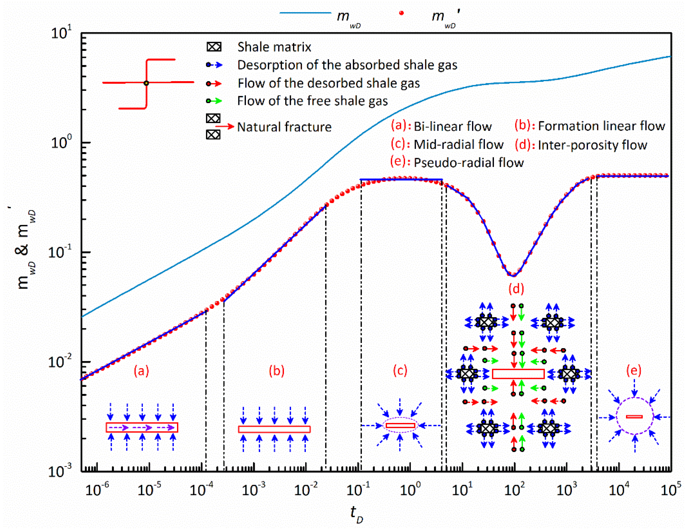
5.1. Flow Regime Identification

Flow regime identification is an important task in well testing and can be used to invert the reservoir or fracture parameters. Figure 4 demonstrates the flow regime identification for a vertically refractured well in a shale gas reservoir with consideration of the mechanism of adsorption and desorption. As presented in Figure 4, there are five typical flow regimes for shale gas flow in the vertically refractured well.
(a)
Bi-linear flow regime: the dimensionless pseudo pressure and pseudo pressure derivative curves are parallel to each other, and the slope of two straight lines is 0.25. Linear flow happens around and inside the artificial fractures in this regime.
(b)
Formation linear flow regime: this regime is generally recognized by two straight lines with the same slope of 0.5 on both the dimensionless pseudo pressure and pseudo pressure derivative curves. There is sufficient gas supply to the artificial fractures and linear flow only occurs around two artificial fractures in this flow mode.
(c)
Mid-radial flow regime: this typical regime often occurs after formation linear flow. In this regime, shale gas flows radially from the formation to the area around two artificial fractures, which is different from the radial flow dominated by the reservoir outer boundary. The duration of the mid-radial flow regime depends on the inter-porosity coefficient and adsorption and desorption constant. Meanwhile, the occurrence of the mid-radial flow regime strongly relates to the storativity ratio between the natural fracture system and shale matrix system.
(d)
Inter-porosity flow regime: this flow regime is characterized by a deep “groove” on the dimensionless pseudo pressure derivative curve. In this regime, the absorbed shale gas that is far away from the refractured well gradually tends to desorb from the shale matrix. Under this circumstance, the desorbed shale gas along with the original free shale gas in natural fractures flows from the far end of the well to the fracture system around the wellbore. The depth of the “groove” largely depends on the storativity ratio and adsorption and desorption constant.
(e)
Pseudo-radial flow regime: in the late period, the dimensionless pseudo pressure derivative curve stabilizes at 0.5 and a pseudo-radial flow regime can be observed. This flow regime occurs when shale gas that is far away from the wellbore flows steadily and radially into natural fractures away from the wellbore.

5.2. Effect of Shale Gas Reservoir Properties and Fracture Reorientation on Transient Pressure of a Refractured Vertical Well

In this section, a single variable control method is adopted to investigate the effects of the properties of the shale gas reservoir and artificial fracture on the transient pseudo pressure, including the storativity ratio, inter-porosity coefficient, adsorption and desorption constant, and fracture reorientation factor. Note that the fracture reorientation factor is a newly defined parameter to quantitatively evaluate the influence of fracture reorientation on the transient pseudo pressure of a refractured well.

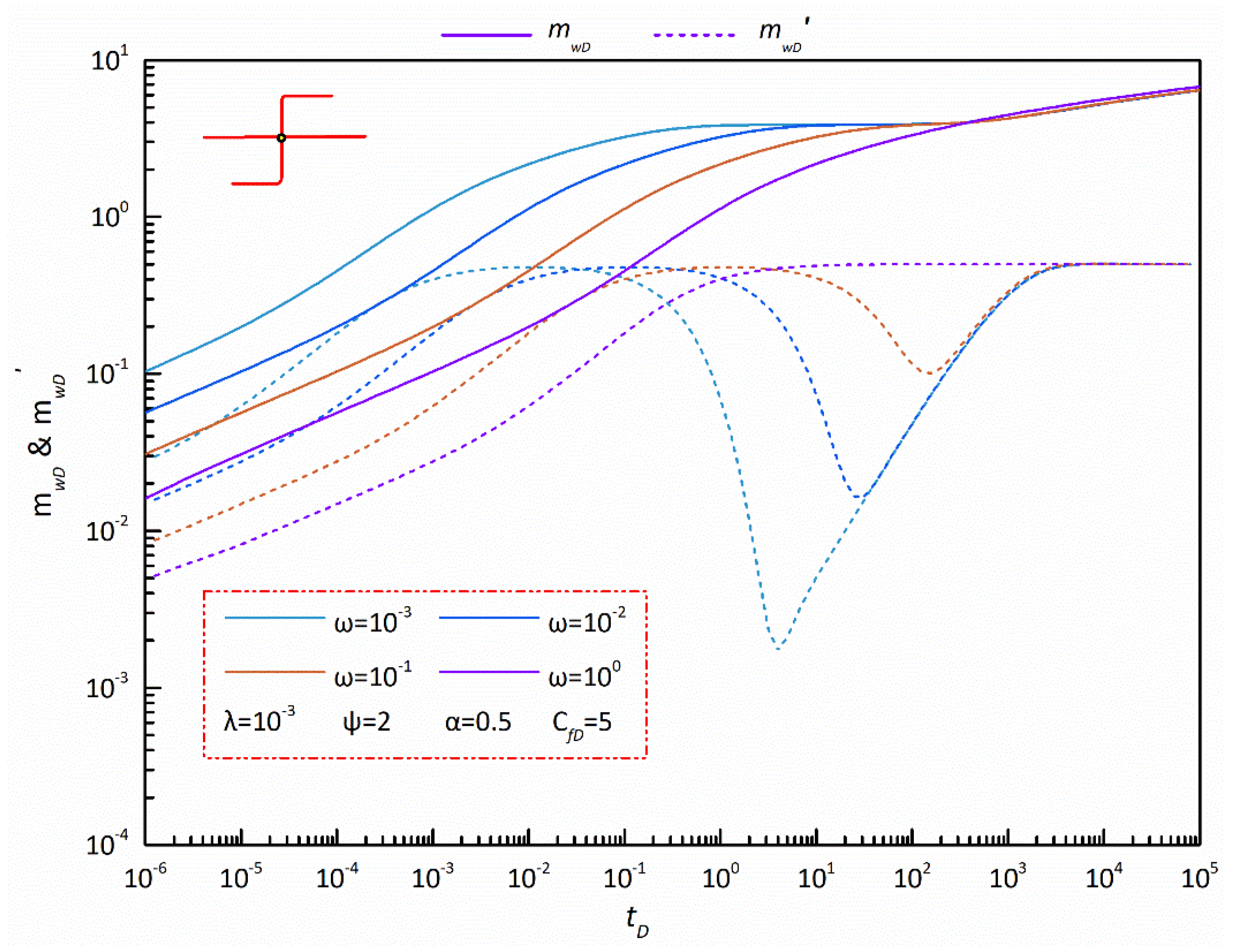
5.2.1. Storativity Ratio between Natural Fracture System and Shale Matrix System

The storativity ratio reflects the difference between the shale gas storage capacity in the shale matrix and the natural fractures. Figure 5 illustrates the influence of the dimensionless storativity ratio on the dimensionless pseudo pressure and pseudo pressure derivative curves for a refractured well with an initial fracture and a reorientation fracture in a shale gas reservoir.
As seen in Figure 5, the storativity ratio mainly affects the early linear flow regime, mid-radial flow regime, and inter-porosity flow regime, while its influence disappears in the pseudo-radial flow regime. It can also be observed that, if the dimensionless storativity ratio gets larger, the linear flow regimes last longer and the mid-radial flow regime appears later. The “groove” on the pseudo pressure derivative curve also becomes shallow or even disappears (short dash violet line in Figure 5) as the dimensionless storativity ratio increases, which can be explained when the storativity ratio increases to some extent, the storativity of the shale matrix is too low to be neglected, and the inter-porosity flow between the shale matrix and natural fractures almost disappears. At the same time, the disappearance of the inter-porosity flow regime results in the combination of the mid-radial flow regime and the pseudo-radial flow regime on the type curves.

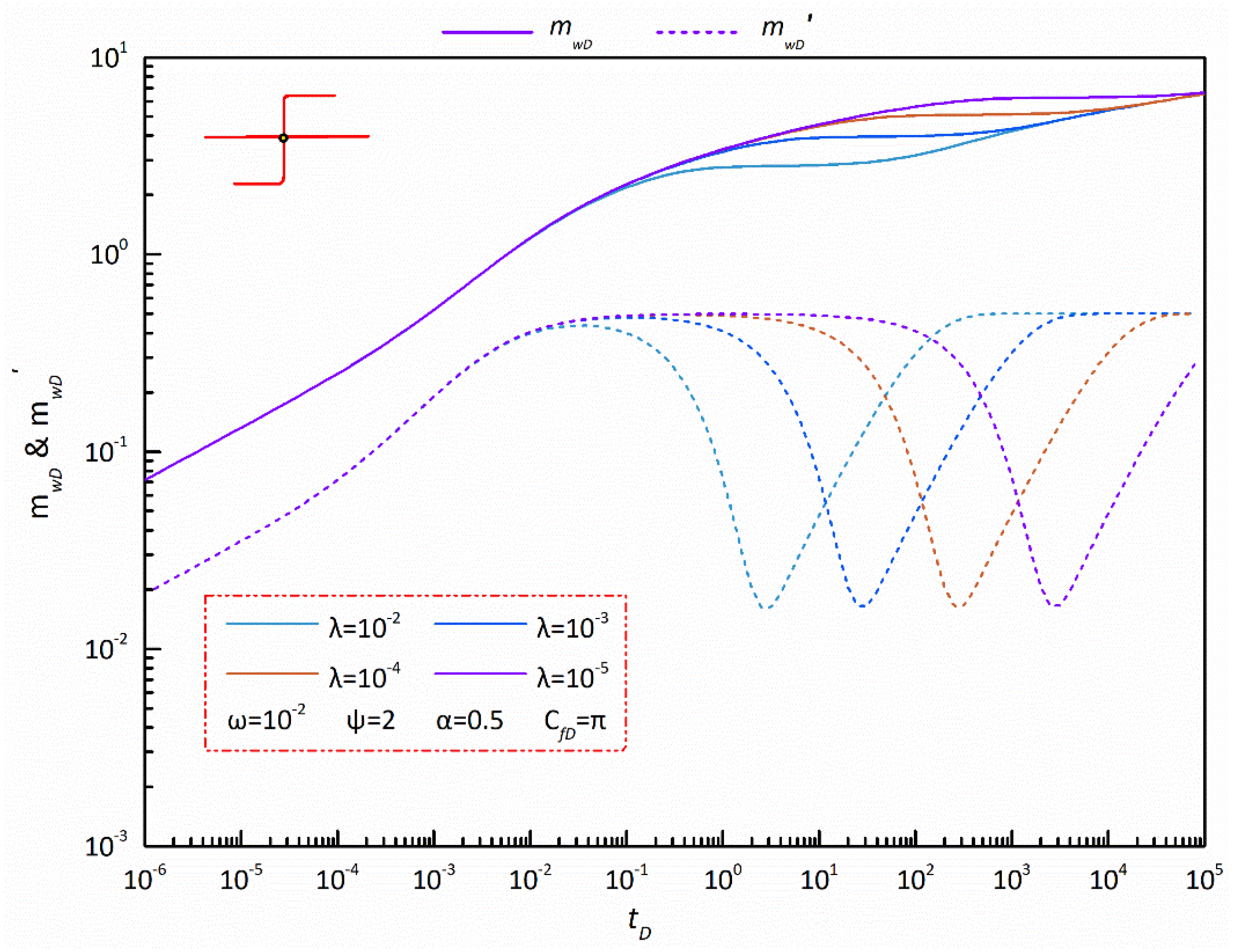
5.2.2. Inter-Porosity Coefficient from Shale Matrix System to Natural Fracture System

Generally, plenty of natural fractures always exist in shale gas reservoirs and the flow capacity of shale gas is totally different in the shale matrix and natural fractures. The inter-porosity coefficient just reflects the ability of the shale matrix system to supply gas to the natural fracture system. Figure 6 shows the effect of the dimensionless inter-porosity coefficient on the dimensionless pseudo pressure and pseudo pressure derivative curves for a refractured well in a shale gas reservoir.
As shown in Figure 6, the effect of the dimensionless inter-porosity coefficient on the pseudo pressure performance can be neglected in the early linear flow regimes. However, its influence on type curves tends to occur after the formation linear flow, and the duration of the mid-radial flow regime tends to last longer with the decrease of this coefficient. This phenomenon can be interpreted as when there is a lower inter-porosity coefficient, the desorbed shale gas diffuses slower into natural fractures and additional time and pressure are needed to maintain the constant flow rate. Meanwhile, the “groove” on the pseudo pressure derivative curve occurs later, but does not disappear when the dimensionless inter-porosity coefficient decreases to some extent, which indicates that the “groove” appears later, but does not disappear in type curves. In addition, the appearance of the pseudo-radial flow regime is also delayed when the dimensionless inter-porosity coefficient becomes low.

5.2.3. Adsorption and Desorption Constant of Shale Gas

For shale gas reservoirs, a large amount of shale gas is adsorbed on the surface of the shale matrix and the adsorbed shale gas becomes free gas through desorption due to the drop in gas reservoir pressure during the withdrawal of shale gas. In order to evaluate the effect of the adsorption and desorption of shale gas on the transient pseudo pressure behavior, a dimensionless adsorption and desorption constant is defined, which is the product of the dimensionless adsorption coefficient and dimensionless desorption coefficient and reflects the ability for adsorption and desorption. The larger the dimensionless adsorption and desorption constant is, the more the adsorbed shale gas in the shale matrix is. The effect of the dimensionless adsorption and desorption constant on the dimensionless pseudo pressure and pseudo pressure derivative curves is displayed in Figure 7.
As displayed in Figure 7, the effect of the dimensionless adsorption and desorption constant on the dimensionless pseudo pressure and pseudo pressure derivative concentrates on the mid-radial flow regime and inter-porosity flow regime. The duration of the mid-radial flow regime is inversely proportional to the dimensionless adsorption and desorption constant, and the corresponding inter-porosity flow regime occurs early when this parameter gets large. Meanwhile, it can be observed in Figure 7 that the width and depth of the “groove” on the pseudo pressure derivative curve is positively proportional to the dimensionless adsorption and desorption constant, which can be explained by increase in adsorbed shale gas in the shale matrix under a larger dimensionless adsorption and desorption constant and leads to an easy diffusion of the shale gas into natural fractures. Hence, the amount of adsorbed shale gas in the shale matrix can be qualitatively assessed through the depth and width of the “groove”.

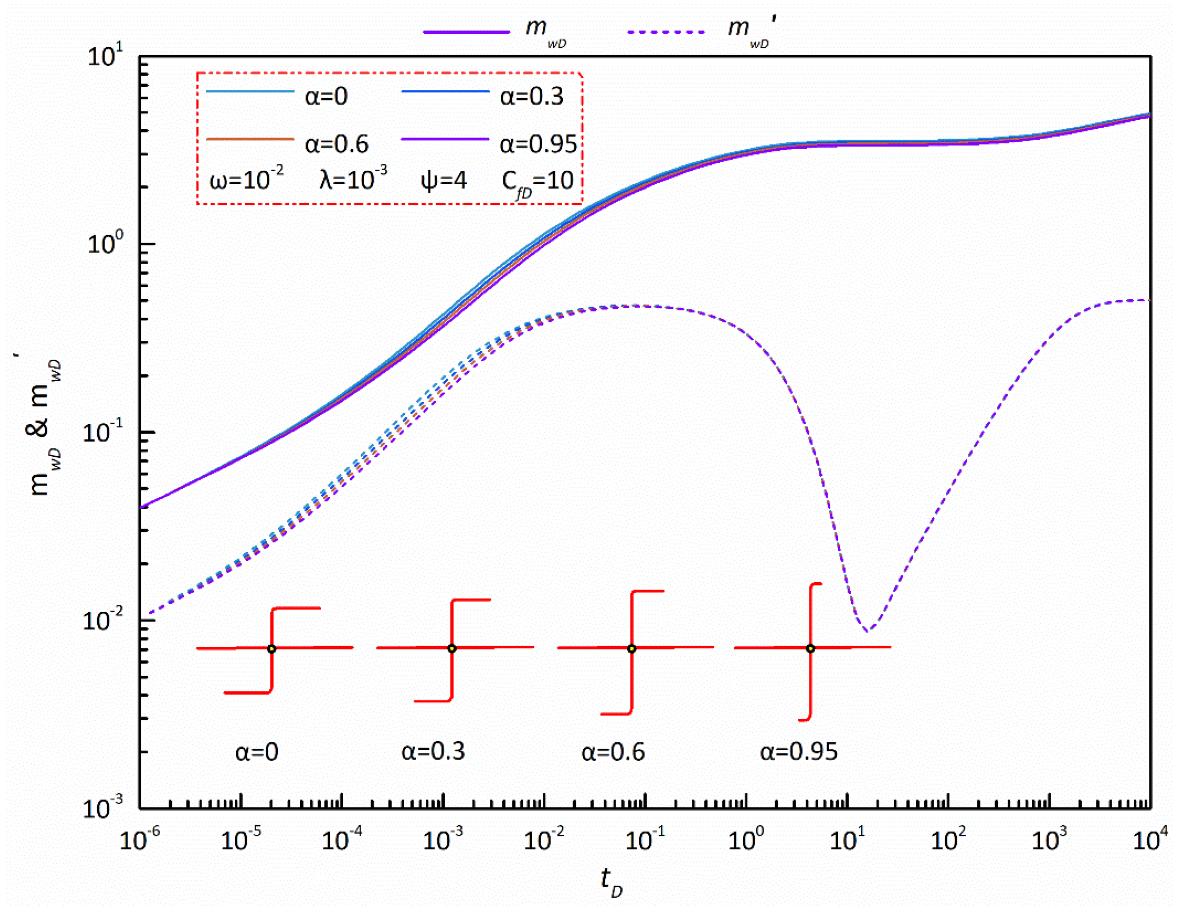
5.2.4. Fracture Reorientation Factor

In order to analyze the effect of fracture reorientation on the dimensionless transient pseudo pressure behavior, a new parameter, namely the fracture reorientation factor, is defined as follows,
α = | R f 2 + R f 3 R f 1 R f 4 | | R f 2 + R f 3 + R f 1 + R f 4 |
When α gets close to zero, the length of the reoriented fracture part is equal to that of the principal fracture part, thereby indicating that fracture reorientation is extremely serious; when α approaches one, fracture reorientation is weak. Meanwhile, we assume that two wings of this reorientation fracture are symmetrical around the intersection point to avoid the effect of the asymmetry of the fracture system on the transient pseudo pressure. Figure 8 demonstrates the transient pseudo pressure behavior of a refractured well with different fracture reorientation factors in a shale gas reservoir.
As shown in Figure 8, the fracture reorientation factor imposes a significant influence on the early flow regimes, including the bi-linear flow regime, formation linear flow regime, and mid-radial flow regime. With the increase of the fracture reorientation factor, the dimensionless pseudo pressure and pseudo pressure derivative get lower and the bi-linear flow regime lasts longer, while the formation linear flow regime appears later and lasts for a shorter time. A reasonable explanation for this phenomenon is that the length of the principal fracture part is much longer when compared to the reoriented fracture part when fracture reorientation factor increases to some degree. Moreover, the shape of the seepage area of a refractured well transitions from circular to elliptical when the fracture reorientation factor increases from 0 to 0.95, and thus the mid-radial flow regime occurs later and lasts for a shorter time.

5.3. Effect of Shale Gas Reservoir Properties and Fracture Reorientation on Transient Rate of a Refractured Well

Both transient pressure analysis and transient rate analysis can help to invert parameters and predict productivity in a well test, and the transient rate analysis can directly present the effects of some properties on the production performance. In this section, the effects of the storativity ratio, inter-porosity coefficient, adsorption and desorption constant, and fracture reorientation factor on the transient rate of a refractured well are discussed further.

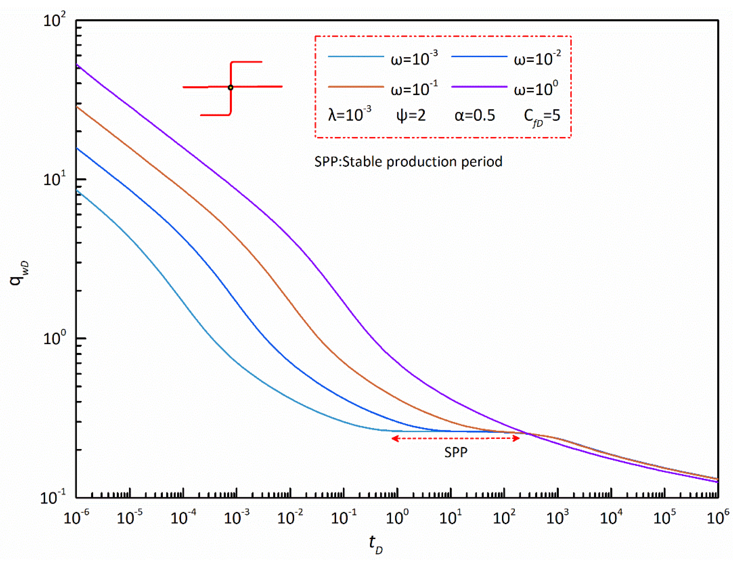
5.3.1. Storativity Ratio between Natural Fracture System and Shale Matrix System

Figure 9 illustrates the influence of the storativity ratio on the transient rate of a vertically refractured well in a shale gas reservoir. On the whole, under constant pressure, the shale gas well productivity decreases rapidly at first, and then slowly after.
In contrast, the dimensionless rate of this refractured well decreases with the decrease of the dimensionless storativity ratio during the rapid decline period. It can be interpreted that the larger the dimensionless storativity ratio is, the more the free gas in natural fractures there is and also the larger the withdrawal of shale gas there is. Meanwhile, the decrement of the dimensionless rate varies in different flow periods under the same decrease of the dimensionless storativity ratio. For example, at tD = 10−5, the dimensionless rate of the refractured well decreases from 15.7654 to 4.2936, with a huge decreasing ratio of 267.18% when the dimensionless storativity ratio decreases from ω = 10−1 to ω = 10−3. However, under the same condition, the decreasing ratio is only 15.045% at tD = 10. This phenomenon indicates that the effect of the storativity ratio on the transient rate becomes gradually weaker as the shale gas continues to be extracted from the reservoir. Moreover, the duration of the stable production period (SPP, the decline rate approaches zero) shortens and even disappears (violet line in Figure 9) with the increase of the dimensionless storativity ratio can be explained when the shale gas reservoir shows the characteristics of a single porosity medium when the dimensionless storativity ratio gets close to one.

5.3.2. Inter-Porosity Coefficient from Shale Matrix System to Natural Fracture System

Figure 10 shows the influence of the dimensionless inter-porosity coefficient, which characterizes the ability of the desorbed shale gas flowing into natural fractures on the dimensionless rate.
As displayed in Figure 10, this coefficient has a strong effect on the middle flow periods and has nearly no effect on the early- and late- flow periods. In the middle flow periods, the rate of the refractured well is positively proportional to this coefficient, and the decrement of the dimensionless rate tends to decrease with the decrease of the dimensionless inter-porosity coefficient. For example, at tD = 10, the dimensionless rate of the refractured well decreases from 0.3527 to 0.2554, with a decreasing ratio of 38.10% when the inter-porosity coefficient decreases from λ = 10−2 to λ = 10−3, while the decreasing ratio is only 16.12% when this coefficient decreases from λ = 10−3 to λ = 10−4, implying that a low inter-porosity coefficient significantly affects the refractured well production in middle flow periods. Similarly, the effect of the dimensionless inter-porosity coefficient on the transient rate gradually weakens with the continuous withdrawal of shale gas. For example, at tD = 103, the dropping ratio of the shale gas rate is 21.22% when the dimensionless inter-porosity coefficient decreases from λ = 10−4 to λ = 10−5, while the dropping ratio is only 14.31% at tD = 104. Moreover, the appearance of the stable production period (SPP, the decline rate approaches zero) delays the increase of the dimensionless inter-porosity coefficient, which can be explained by the increase of the dimensionless inter-porosity coefficient, which results in the delay of the inter-porosity flow.

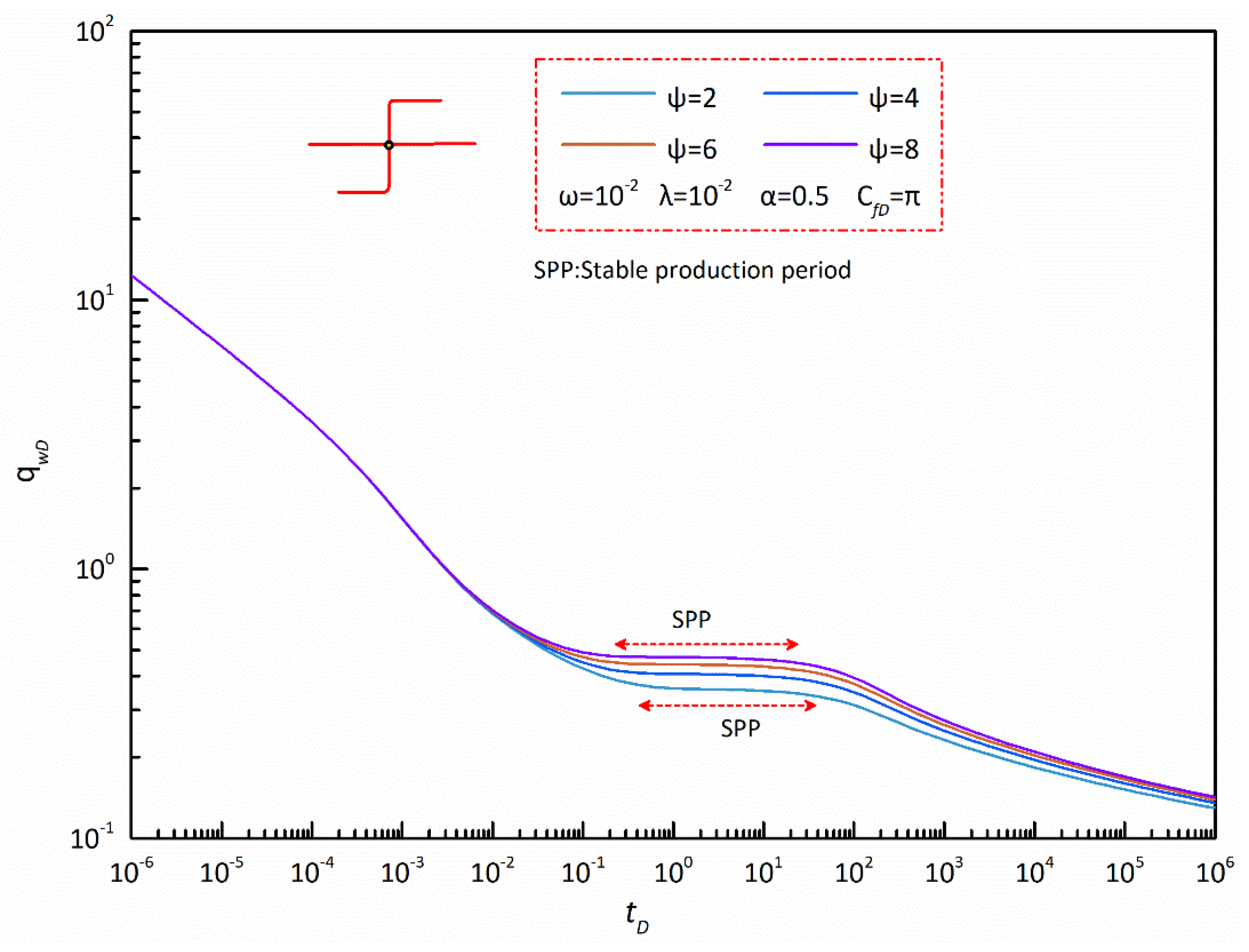
5.3.3. Adsorption and Desorption Constant

Adsorbed gas and free gas exist in the shale matrix and natural fractures, respectively. Adsorbed shale gas first becomes free gas through desorption and then flows into natural fractures and artificial fractures, and finally is produced from vertical wellbore. Figure 11 demonstrates the effect of adsorption and desorption on the transient rate of a refractured well in a shale gas reservoir.
As shown in Figure 11, the dimensionless adsorption and desorption constant affects all flow periods except the early flow period. In the stable production period (SPP), the dimensionless rate has a positively proportional relationship with the dimensionless adsorption and desorption constant. Meanwhile, the decrement of the dimensionless rate tends to be strengthened as the dimensionless adsorption and desorption constant decreases. For example, at tD = 2, when this parameter decreases from 6 to 4, the rate of the refractured well drops from 0.4411 to 0.4064 with a decreasing ratio of 7.88%, while the decreasing ratio is up to 11.98% when the dimensionless adsorption and desorption constant decreases from 4 to 2. This feature implies that when this constant decreases to some degree, the dimensionless rate of the refractured well will be relatively low during SPP, which can be explained by the free gas in natural fractures that is almost extracted at the early flow periods while the adsorbed shale gas is not enough to maintain high production in this period. Moreover, the appearance of SPP causes a slightly delay from the decrease of the dimensionless adsorption and desorption constant. In the late flow period, the effect of this constant on the transient rate is rather weak compared to that in the stable production period.

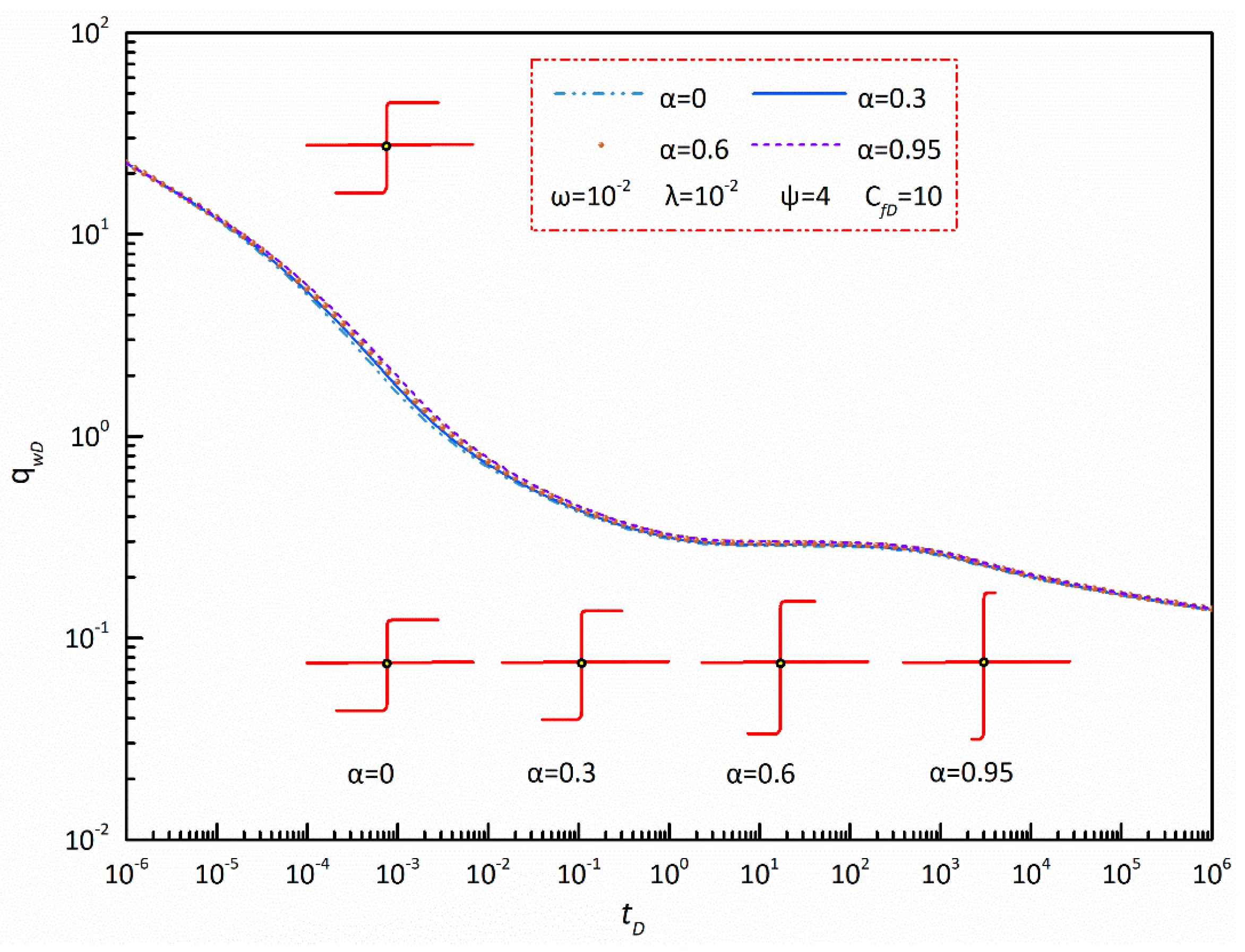
5.3.4. Fracture Reorientation Factor

Figure 12 illustrates the influence of the fracture reorientation factor on the transient rate for a refractured well in a shale gas reservoir. It can be observed in Figure 12 that the effect of the fracture reorientation factor on the dimensionless rate concentrates on the early flow periods. In the bi-linear flow regime, the difference in the dimensionless rate caused by the fracture reorientation factor can be neglected. After the bi-linear flow regime, the impact of the fracture reorientation factor begins to occur, and the dimensionless rate of the refractured well shows an inversely proportional relationship with fracture reorientation, which can explain why the more serious the fracture reorientation is, the longer the length of the reoriented fracture is and also the larger the seepage area of the refractured well is. From the above phenomenon, it can be concluded that a large fracture reorientation factor is conducive to enhancing the productivity of a refractured well in a shale gas reservoir.

6. Conclusions

This work has developed a semi-analytical solution for a refractured well model in a shale gas reservoir with consideration of the effect of absorption and desorption and fracture reorientation. The transient behavior of the pseudo pressure and rate of the refractured well was also discussed, and the following conclusions can be obtained:
  • For a refractured well in a shale gas reservoir with absorption and desorption and fracture reorientation, five typical flow regimes are identified on type curves: bi-linear flow regime, formation linear flow regime, mid-radial flow regime, inter-porosity flow regime, and pseudo-radial flow regime.
  • According to the flow regime identification, a “groove” can be observed on the dimensionless pseudo pressure derivative curve, which corresponds to the inter-porosity flow regime. The larger the dimensionless storativity ratio or adsorption and desorption constant is, the later this flow regime appears and also the shallower and narrower the “groove” is. The dimensionless inter-porosity coefficient only affects the appearance of the “groove” but has no influence on its width and depth.
  • Fracture reorientation imposes a weak influence on the linear flow regimes and mid-radial flow regime, and in these flow regimes a long extension of the principal fracture corresponds to a lower pressure loss.
  • A short, stable production period can be observed on the dimensionless rate transient curves and its duration is closely related to the dimensionless storativity ratio. The dimensionless rate during this period depends on the dimensionless inter-porosity coefficient and dimensionless adsorption and desorption constant.
  • The transient rate of the refractured well in a shale gas reservoir is positively proportional to the dimensionless storativity ratio, dimensionless inter-porosity coefficient, and dimensionless adsorption and desorption constant, but inversely proportional to the fracture reorientation.

Author Contributions

All authors have contributed to this work. X.D. established the mathematical model, wrote the main manuscript and compiled the corresponding mathematical algorithm of this work. G.X. made substantial contributions to the conception/design of the work as the corresponding author. S.H., Z.T. and J.L. contributed to the modeling, drawing, and results analysis and discussion. All authors have read and agreed to the published version of the manuscript.

Funding

This study was funded by the National Natural Science Foundation of China (Program No. 52004038), the Natural Science Research of Jiangsu Higher Education Institutions of China (Program No. 20KJB440003).

Data Availability Statement

All the data have been included in the manuscript.

Conflicts of Interest

The authors declare no conflict of interest.

Nomenclature

Field Variables
ZShale gas compressibility factor, fraction
TTemperature, K
pPressure, MPa
tTime, s
wfHydraulic fracture width, m
μFluid viscosity, Pa·s
φPorosity, fraction
ρShale gas density, g/m3
rfEquivalent half length, m
vShale gas velocity, m/s
VmAdsorption concentration of shale matrix particles, m3/m3
VEEquilibrium adsorption concentration, m3/m3
DDiffusion coefficient, m2/s
αShape factor of matrix block, fraction
VLLangmuir’s volume, m3/m3
ViInitial adsorption volume, m3/m3
rf1 + rf2Length of initial fracture, m
Rf1 + Rf3Length of principal fracture in a reorientation fracture, m
Rf2 + Rf4Length of reoriented fracture in reorientation fracture, m
Dimensionless Variables
CfDDimensionless facture conductivity
tDDimensionless time
m ˜ D Dimensionless pseudo pressure in Laplace domain
mDDimensionless pseudo pressure in real time domain
xDDimensionless length in the x-axis
yDDimensionless length in the y-axis
reDDimensionless radial length
ωDimensionless storativity ratio
λDimensionless inter-porosity coefficient
βDimensionless desorption coefficient
εDimensionless adsorption coefficient
ψDimensionless adsorption and desorption constant
q ˜ D Dimensionless point source flux
lDDimensionless length of line source
x D Dimensionless length in the x-axis after Cartesian-coordinate rotation
y D Dimensionless length in the y-axis after Cartesian-coordinate rotation
q ˜ f D Dimensionless point source flux in a fracture
αFracture reorientation factor
Subscripts
fgNatural fracture property in the shale gas reservoir
fmMatrix property in the shale gas reservoir
fHydraulic fracture property
DDimensionless
wWellbore property
scStandard condition
Special Functions
K0(x)Modified Bessel function (second kind, zero order)

Appendix A. Dimensionless Definitions

To convert the governing equation and initial-boundary conditions more concise, the following dimensionless variables are defined.
The dimensionless pseudo pressure in shale gas reservoirs and natural or artificial fractures are given as,
m D = π k f g h Z s c T s c ( m i m ) q s c p s c T m f D = π k f g h Z s c T s c ( m i m f ) q s c p s c T
Here mi is the pseudo pressure corresponding to the initial pressure in shale gas reservoirs and kfg is the gas permeability of natural fractures in shale gas reservoirs. The subscript (sc) represents the fluid properties under standard condition.
The dimensionless production time is,
t D = k f g t [ ( μ ϕ c t ) f g + ( μ ϕ c t ) f m ] r f 2
In this work, rf represents the equivalent half-length of artificial fractures and thus rf can be written as,
r f = r f 1 + r f 2 + R f 1 + R f 2 + R f 3 + R f 4 4
where rf1 and rf2 are the length of two wings of initial fracture respectively, and Rf1, Rf2, Rf3, Rf4 are the length of principal fracture part and reoriented fracture parts of reorientation fracture.
For the proposed fracture model in this work, the dimensionless fracture conductivity, CfD, is,
C f D = k f w f k f g r f
Here wf is fracture width and kf is fracture permeability.
The dimensionless radial distance, rD, is,
r D = r r f
To characterize the fluid flow in shale matrix and natural fractures, we define the dimensionless storativity ratio and inter-porosity coefficient respectively,
ω = ( μ ϕ c t ) f g [ ( μ ϕ c t ) f g + ( μ ϕ c t ) f m ]
λ = D α ( μ ϕ c t ) f m k f g r f 2
where D is diffusion coefficient, m2/s; α is shape factor of shale matrix block. The subscripts fm and fg represent the properties of shale matrix and natural fractures in shale gas reservoirs.
To evaluate the adsorption and desorption of shale gas at shale matrix surface, the dimensionless desorption coefficient and adsorption coefficient can be defined respectively,
β = 2 π h V i k f g ρ s c q s c ( μ ϕ c t ) f m
ε = m L ( m + m L ) m i q s c p s c T π k f g h Z s c T s c
where Vi is the initial adsorption volume of shale gas, m3/m3, mL is the pseudo pressure corresponding to equilibrium adsorption concentration and VL is Langmuir’s volume, m3/m3.
Combining Equations (A8) and (A9) yields the dimensionless adsorption and desorption constant, which reflects the ability of adsorption and desorption,
ψ = β ε
Meanwhile, the dimensionless adsorption concentration of shale gas in shale matrix particles can defined as follows,
V m D = V i V m V i
And the dimensionless flow rate of per unit fracture length, qDi, is defined as,
q D i = q i q s c
Moreover, the dimensionless flow rate strength, qfD, is written as,
q f D = q f r f q s c
where qf is the flow rate of per unit fracture length.

Appendix B. Point-Source Solution of the Physical Model

To obtain a semi-analytical solution for a refractured well in a shale gas reservoir, the point-source solution of this physical model (shown in Figure 1) is obtained firstly. The continuity equation can be written as Equation (A14) in radial coordinates,
1 r ( r ρ v r ) r = ( ρ ϕ ) t + V m t
where Vm is the adsorption concentration of shale matrix particles, m3/m3.
According to Darcy’s law, the following equation can be obtained,
v r = k f g μ p r
Based on gas state equation, the following equation can be written,
ρ = T s c Z s c ρ s c p s c p Z T
Further, the pseudo-pressure function is defined as follows,
m ( p ) = 0 p 2 p μ Z d p
Combining Equation (A14) to Equation (A17) can yield,
k f g ( 2 m r 2 + 1 r m r ) = ( ϕ μ C t ) f m t + 2 p s c T T s c Z s c ρ s c V m t
Equation (A18) is the partial-differential equation to describe the flow behavior in the shale gas reservoir.
The initial reservoir condition is:
m ( r , t = 0 ) = m i
The inner boundary and outer boundary conditions are,
π r h k f g Z s c T s c p s c T m r | r 0 = q i
m ( p ) | r = m i
After the desorption of the shale gas adsorbed in shale matrix, it obeys Fick’s law and thus we can yield,
V m t = D α ( V m V E )
where VE is equilibrium adsorption concentration, m3/m3.
Meanwhile, the adsorption of shale gas in shale matrix follows Langmuir isothermal adsorption law and thus we can yield,
V = V L m m L + m
The initial adsorption volume is:
V | t = 0 = V i ( m i )
By using the related dimensionless definitions in Appendix A, the dimensionless governing equation and boundary conditions for shale gas reservoir can be obtained.
2 m D r D 2 + 1 r D m D r D = ω m D t D + β ( 1 ω ) V m D t D
( r D m D r D ) | r D 0 = q D i
m D | r D = 0
m D ( r D , t D = 0 ) = 0
( 1 ω ) V m D t D = λ ( V E D V m D )
V E D = ε m D
The following equations can be yielded by imposing Laplace transform on Equation (A25) to Equation (A30),
{ 2 m ˜ D r D 2 + 1 r D m ˜ D r D = s f ( s ) m ˜ D ( r D m ˜ D r D ) | r D 0 = q ˜ D i m ˜ D | r D = 0
where
f ( s ) = ω λ + ( 1 ω ) ( ψ λ + ω s ) ( 1 ω ) s + λ
In Equation (A32), ψ is the dimensionless adsorption and desorption constant.
The point-source solution for the shale gas reservoir can be obtained by solving the above equations,
m ˜ D ( r D , s ) = q ˜ D i ( s ) K 0 ( s f ( s ) r D )

References

  1. Benedict, D.S.; Miskimins, J.L. Analysis of reserve recovery potential from hydraulic fracture reorientation in tight gas Lenticular reservoirs. In Proceedings of the SPE Hydraulic Fracturing Technology Conference, The Woodlands, TX, USA, 19–21 January 2009. SPE-119355-MS. [Google Scholar] [CrossRef]
  2. Indras, P.; Blankenship, C. A commercial evaluation of refracturing horizontal shale wells. In Proceedings of the SPE Annual Technical Conference and Exhibition, Houston, TX, USA, 28–30 September 2015. SPE-174951-MS. [Google Scholar] [CrossRef]
  3. Xu, T.; Lindsay, G.; Baihly, J.; Ejofodomi, E.; Malpani, R.; Shan, D. Proposed refracturing methodology in the Haynesville shale. In Proceedings of the SPE Annual Technical Conference and Exhibition, San Antonio, TX, USA, 9–11 October 2017. SPE-187236-MS. [Google Scholar] [CrossRef]
  4. Siebrits, E.; Elbel, J.L.; Hoover, R.S.; Diyashev, I.R.; Griffin, L.G.; Demetrius, S.L.; Wright, C.A.; Davidson, B.M.; Steinsberger, N.P.; Hill, D.G. Refracture reorientation enhances gas production in Barnett shale tight gas wells. In Proceedings of the SPE Annual Technical Conference and Exhibition, Dallas, TX, USA, 1–4 October 2000. SPE-63030-MS. [Google Scholar] [CrossRef]
  5. Diakhate, M.; Gazawi, A.; Barree, B.; Cossio, M.; Tinnin, B.; McDonald, B.; Barzola, G. Refracturing on horizontal wells in the Eagle Ford Shale in South Texas-one operator’s perspective. In Proceedings of the SPE Hydraulic Fracturing Technology Conference, The Woodlands, TX, USA, 3–5 February 2015. SPE-173333-MS. [Google Scholar] [CrossRef]
  6. Shah, M.; Shah, S.; Sircar, A. A comprehensive overview on recent developments in refracturing technique for shale gas reservoirs. J. Nat. Gas Sci. Eng. 2017, 46, 350–364. [Google Scholar] [CrossRef]
  7. Xing, G.; Wang, M.; Zhang, Y.; Shi, H.; Guo, W.; Li, T.; Luo, R.; Dou, X. Productivity evaluation of refracturing to a poorly/damaged fractured well in a tight reservoir. Arab. J. Sci. Eng. 2021, 46, 1–24. [Google Scholar] [CrossRef]
  8. Saputra, W.; Kirati, W.; Patzek, T.W. Generalized extreme value statistics, physical scaling and forecasts of gas production in the Haynesville shale. J. Nat. Gas Sci. Eng. 2021, 94, 104041. [Google Scholar] [CrossRef]
  9. Nobakht, M.; Clarkson, C.R.; Kaviani, D. New type curves for analyzing horizontal well with multiple fractures in shale gas reservoirs. J. Nat. Gas Sci. Eng. 2013, 10, 99–112. [Google Scholar] [CrossRef]
  10. Sang, Y.; Chen, H.; Yang, S.; Guo, X.; Zhou, C.; Fang, B.; Zhou, F.; Yang, J.K. A new mathematical model considering adsorption and desorption process for productivity prediction of volume fractured horizontal wells in shale gas reservoirs. J. Nat. Gas Sci. Eng. 2014, 19, 228–236. [Google Scholar] [CrossRef]
  11. Chen, Z.; Liao, X.; Zhao, X.; Dou, X.; Zhu, L. Performance of horizontal wells with fracture networks in shale gas formation. J. Pet. Sci. Eng. 2015, 133, 646–664. [Google Scholar] [CrossRef]
  12. Kim, T.H.; Lee, K.S. Pressure-transient characteristics of hydraulically fractured horizontal wells in shale-gas reservoirs with natural-and rejuvenated-fracture networks. J. Can. Pet. Technol. 2015, 54, 245–258. [Google Scholar] [CrossRef]
  13. Guo, J.J.; Wang, H.T.; Zhang, L.H. Transient pressure and production dynamics of multi-stage fractured horizontal wells in shale gas reservoirs with stimulated reservoir volume. J. Nat. Gas Sci. Eng. 2016, 35, 425–443. [Google Scholar] [CrossRef]
  14. Kim, T.H.; Lee, J.H.; Lee, K.S. Integrated reservoir flow and geomechanical model to generate type curves for pressure transient responses of a hydraulically-fractured well in shale gas reservoirs. J. Pet. Sci. Eng. 2016, 146, 457–472. [Google Scholar] [CrossRef]
  15. Lu, T.; Li, Z.; Lai, F.; Meng, Y.; Ma, W.; Sun, Y.; Wei, M. Blasingame decline analysis for variable rate/variable pressure drop: A multiple fractured horizontal well case in shale gas reservoirs. J. Pet. Sci. Eng. 2019, 178, 193–204. [Google Scholar] [CrossRef]
  16. Dahim, S.; Taghavinejad, A.; Razghandi, M.; Rigi, H.R.; Moeini, K.; Jamshidi, S.; Sharifi, M. Pressure and rate transient modeling of multi fractured horizontal wells in shale gas condensate reservoirs. J. Pet. Sci. Eng. 2020, 185, 106566. [Google Scholar] [CrossRef]
  17. Xu, Y.J.; Li, X.P.; Liu, Q.G. Pressure performance of multi-stage fractured horizontal well with stimulated reservoir volume and irregular fractures distribution in shale gas reservoirs. J. Nat. Gas Sci. Eng. 2020, 77, 103209. [Google Scholar] [CrossRef]
  18. Xu, Y.; Liu, Q.; Li, X.; Meng, Z.; Yang, S.; Tan, X. Pressure transient and Blasingame production decline analysis of hydraulic fractured well with induced fractures in composite shale gas reservoirs. J. Nat. Gas Sci. Eng. 2021, 94, 104058. [Google Scholar] [CrossRef]
  19. Huang, T.; Guo, X.; Chen, F.F. Modeling transient pressure behavior of a fractured well for shale gas reservoirs based on the properties of nanopores. J. Nat. Gas Sci. Eng. 2015, 23, 387–398. [Google Scholar] [CrossRef]
  20. Chen, Z.; Liao, X.; Zhao, X.; Zhu, L. Influence of magnitude and permeability of fracture networks on behaviors of vertical shale gas wells by a free-simulator approach. J. Pet. Sci. Eng. 2016, 147, 261–272. [Google Scholar] [CrossRef]
  21. Zhang, Q.; Su, Y.; Wang, W.; Lu, M.; Ren, L. Performance analysis of fractured wells with elliptical SRV in shale reservoirs. J. Nat. Gas Sci. Eng. 2017, 45, 380–390. [Google Scholar] [CrossRef]
  22. Zhang, R.H.; Zhang, L.H.; Tang, H.Y.; Chen, S.N.; Zhao, Y.L.; Wu, J.F.; Wang, K.R. A simulator for production prediction of multistage fractured horizontal well in shale gas reservoir considering complex fracture geometry. J. Nat. Gas Sci. Eng. 2019, 67, 14–29. [Google Scholar] [CrossRef]
  23. Cui, Y.; Jiang, R.; Wang, Q.; Liu, X. Production performance analysis of multi-fractured horizontal well in shale gas reservoir considering space variable and stress-sensitive fractures. J. Pet. Sci. Eng. 2021, 207, 109171. [Google Scholar] [CrossRef]
  24. Lin, R.; Li, G.M.; Zhao, J.Z.; Ren, L.; Wu, J.F. Productivity model of shale gas fractured horizontal well considering complex fracture morphology. J. Pet. Sci. Eng. 2022, 208, 109511. [Google Scholar] [CrossRef]
  25. Zhai, Z.Y.; Sharma, M.M. Estimating fracture reorientation due to long term fluid injection/production. In Proceedings of the Production and Operations Symposium, Oklahoma City, OK, USA, 27–29 March 2007. SPE-106387-MS. [Google Scholar] [CrossRef]
  26. Kuzmina, S.; Butula, K.K.; Nikitin, A. Reservoir pressure depletion and water flooding influencing hydraulic fracture orientation in low-permeability oilfields. In Proceedings of the 8th European Formation Damage Conference, Scheveningen, The Netherlands, 27 May 2009. SPE-120749-MS. [Google Scholar] [CrossRef]
  27. Tavassoli, S.; Yu, W.; Javadpour, F.; Sepehrnoori, K. Selection of candidate horizontal wells and determination of the optimal time of refracturing in Barnett Shale (Johnson County). In Proceedings of the SPE Unconventional Resources Conference Canada, Calgary, AB, Canada, 5–7 November 2013. SPE-167137-MS. [Google Scholar] [CrossRef]
  28. Li, X.; Wang, J.H.; Elsworth, D. Stress redistribution and fracture propagation during restimulation of gas shale reservoirs. J. Pet. Sci. Eng. 2017, 154, 150–160. [Google Scholar] [CrossRef]
  29. Teng, B.L.; Li, H.Z.A. A semi-analytical model for characterizing the fluid transient flow of reoriented refractures. J. Pet. Sci. Eng. 2019, 177, 921–940. [Google Scholar] [CrossRef]
  30. Wu, S.; Xing, G.; Cui, Y.; Wang, B.; Shi, M.; Wang, M. A semi-analytical model for pressure transient analysis of hydraulic reorientation fracture in an anisotropic reservoir. J. Pet. Sci. Eng. 2019, 179, 228–243. [Google Scholar] [CrossRef]
  31. Xing, G.; Wu, S.; Wang, J.; Wang, M.; Wang, B.; Cao, J. Pressure transient performance for a horizontal well intercepted by multiple reorientation fractures in a tight reservoir. Energies 2019, 12, 4232. [Google Scholar] [CrossRef] [Green Version]
  32. Luo, L.; Cheng, S.Q.; Lee, J. Characterization of refracture orientation in poorly propped fractured wells by pressure transient analysis: Model, pitfall, and application. J. Nat. Gas Sci. Eng. 2020, 79, 103332. [Google Scholar] [CrossRef]
  33. Jiang, L.; Liu, J.; Liu, T.; Yang, D. Production decline analysis for a fractured vertical well with reorientated fractures in an anisotropic formation with an arbitrary shape using the boundary element method. J. Pet. Sci. Eng. 2021, 208, 109213. [Google Scholar] [CrossRef]
  34. Stehfest, H. Algorithm 368: Numerical Inversion of Laplace Transforms. Commun. ACM 1970, 13, 47–49. [Google Scholar] [CrossRef]
  35. Van Everdingen, A.F.; Hurst, W. The application of the Laplace transformation to flow problems in reservoirs. J. Pet. Technol. 1949, 1, 305–324. [Google Scholar] [CrossRef]
Figure 1. Schematic of physical model for a refractured well in a shale gas reservoir.
Energies 15 04345 g001
Figure 2. Cartesian-coordinate rotation of a line source with an arbitrary azimuthal angle.
Energies 15 04345 g002
Figure 3. Comparison of transient pressure calculated by our semi-analytical model with the results obtained from the commercial software.
Energies 15 04345 g003
Figure 4. Flow regime identification for a refractured vertical well in a shale gas reservoir.
Energies 15 04345 g004
Figure 5. Effect of dimensionless storativity ratio on transient pressure of a refractured well.
Energies 15 04345 g005
Figure 6. Effect of dimensionless inter-porosity coefficient on transient pressure of a refractured well.
Energies 15 04345 g006
Figure 7. Effect of dimensionless adsorption and desorption constant on transient pressure of a refractured well.
Energies 15 04345 g007
Figure 8. Effect of fracture reorientation factor on transient pressure of a refractured well.
Energies 15 04345 g008
Figure 9. Effect of dimensionless storativity ratio on transient rate of a refractured well.
Energies 15 04345 g009
Figure 10. Effect of dimensionless inter-porosity coefficient on transient rate of a refractured well.
Energies 15 04345 g010
Figure 11. Effect of dimensionless adsorption and desorption constant on transient rate of a refractured well.
Energies 15 04345 g011
Figure 12. Effect of fracture reorientation factor on transient rate of a refractured well.
Energies 15 04345 g012
Publisher’s Note: MDPI stays neutral with regard to jurisdictional claims in published maps and institutional affiliations.

