Article

An Appropriate Index to Assess the Global Cancellation Level of the Harmonic Currents Consumed by a Set of Single-Phase Uncontrolled Rectifiers and a Set of Fluorescent Lamps

1
Department of Electrical Engineering (EEBE-UPC), Universitat Politècnica de Catalunya, Av. Eduard Maristany 16, 08019 Barcelona, Spain
2
Department of Electrical Engineering (ETSEIB-UPC), Universitat Politècnica de Catalunya, Av. Diagonal 647, 08028 Barcelona, Spain
3
Department of Electrical Engineering (EPSEVG-UPC), Universitat Politècnica de Catalunya, Av. Víctor Balaguer 1, 08800 Vilanova i la Geltrú, Spain
*
Author to whom correspondence should be addressed.
Energies 2022, 15(12), 4315; https://doi.org/10.3390/en15124315
Submission received: 30 April 2022 / Revised: 3 June 2022 / Accepted: 8 June 2022 / Published: 13 June 2022
(This article belongs to the Special Issue Power Quality in the Modeling of Machines and Electrical Devices)

Abstract

:
An in-depth study of harmonic current reduction in European commercial buildings due to the harmonic cancellation effect when a set of single-phase uncontrolled rectifiers and a set of fluorescent lamps are connected at the same voltage level is essential, since both types of non-linear loads are very present in commercial and residential sectors. This paper provides an appropriate index to assess the global cancellation level of the harmonic currents for this study. The equivalent circuit per phase of the typical three-phase power system of European commercial installations is presented and simplified for the cancellation analysis of the harmonic currents consumed by a set of multiple identical single-phase uncontrolled rectifiers and a set of multiple identical fluorescent lamps connected at the same voltage level. The suitability and usefulness of the proposed index are shown by applying it to that analysis, which leads to some results of practical interest. This index can be generalized to any number of sets of multiple identical non-linear loads and can be applied in graphical and optimization studies that will allow a greater benefit from the harmonic cancellation effect to be obtained given the global nature of the index.

1. Introduction

The growing presence of non-linear loads (NLLs) in commercial and residential installations has raised the harmonic distortion levels in power distribution systems [1,2]. NLLs in these installations are mainly small-power single-phase loads in the 15–300 W range, but high-power three-phase loads in the 15–75 kW range are significantly increasing (see Table 1). Small-power single-phase NLLs are switched-mode power supplies of office and entertainment equipment, as well as lighting devices. They include, for example, single-phase uncontrolled rectifiers (URs) representing power supplies of personal computers (PCs) (units in the 100–300 W range), and fluorescent lamps (FLs) and compact fluorescent lamps (CFLs), representing magnetically and electronically ballasted lighting devices (units in the 15–80 W range), respectively. It should be noted that the waveforms of currents consumed by some CFLs and some LED lamps are similar to those of URs, which makes it possible to treat these lamps as URs. High-power NLLs are three-phase uncontrolled rectifiers representing adjustable-speed drives (ASDs) for heating, ventilation, and air-conditioning (HVAC) equipment, and phase-controlled rectifiers for temperature regulation of residential households [3]. Although the individual power consumption of NLLs of the first group is small, their collective power consumption can be as high as that of the second group because many of these loads can be connected to the same bus.
As an example of a commercial installation, the typical three-phase, four-wire power system of a European commercial office building is shown in Figure 1. The utility incoming medium voltage (MV) is transformed to 400/230 V low-voltage (LV) levels at the point where three- and single-phase loads share the MV/LV transformer. Three-phase linear and non-linear loads are connected at the line-to-line 400 V level, while single-phase NLLs such as office equipment and lighting devices are connected at the line-to-neutral 230 V level. In North American commercial office buildings, a 480/277 to 208/120 V delta-wye transformer separates three-phase loads and lighting devices from single-phase loads connected at the voltage levels of 480, 277, and 120 V, respectively [3,4]. On the other hand, the typical residential installation has a one-line diagram remarkably similar to that of the European commercial office building of Figure 1. The main difference between both installations is the type of connected loads.
It is known that the fixed harmonic current method for modeling NLL behavior leads to an overestimation of the harmonic currents consumed by the aggregate of the NLLs of the above installations, because the harmonic attenuation and cancellation effects [3,4,5,6,7,8,9,10,11,12,13,14,15,16,17] can significantly reduce these currents. The harmonic attenuation effect refers to the interaction between voltage and current distortion due to shared system impedance [5,13]. The harmonic cancellation effect is owing to the phase angle diversity of harmonic currents due to the following factors: (1) three- and single-phase loads connected at the same voltage level, (2) similar types of loads with differences in system impedances and load parameters, (3) different types of loads connected at the same voltage level, and (4) delta-wye transformer phase shift for single-phase loads connected at two different voltage levels. Some of these harmonic current reduction causes have already been analyzed in the literature. For example, the attenuation and cancellation effects (cancellation effect due to the second factor) on PC harmonic currents are studied in [3,6,7,8,9,15]. Cancellation of harmonic currents consumed by HVAC equipment and PCs due to the first factor is studied in [3,10], and by lighting devices and PCs due to the third factor is studied in [3,11,12,14,16]. Harmonic cancellation due to the first and third factors is not usual in North American commercial installations because a 480/277 to 208/120 V delta-wye transformer separates HVAC equipment and lighting devices from PCs. However, harmonic cancellation due to the fourth factor is commonly present in these installations [3,4].
Several indexes have been proposed to assess the cancellation level of the harmonic currents consumed by NLLs. They can be grouped under those that assess the cancellation level of individual harmonic currents and those that assess the global cancellation level of harmonic currents. Indexes such as the summation exponent or summation coefficient [17,18,19], the diversity factor [3,6,8,12,15,17,18,19,20,21,22,23,24,25,26,27,28], the weighted-average diversity factor [29], and the prevailing ratio [30] belong to the first group, whereas indexes such as the total equivalent CFL index in combination with the total compatibility index [31] belong to the second group.
Among the indexes to assess the cancellation level of individual harmonic currents, the summation exponent or summation coefficient is the only index that assesses the cancellation level of individual harmonic currents when their phase angles are not available, but their magnitudes are. However, the value of this index must be obtained by solving a non-linear equation iteratively and, under some conditions, the equation may not have a solution. If both the magnitudes and phase angles of the harmonic currents are available, the diversity factor is the appropriate index to assess the cancellation level of individual harmonic currents. This index has a more general version, known as the weighted-average diversity factor, which is normally used when the diversity factors of different aggregations of loads are available. Another general version of the diversity factor is the prevailing ratio, which is usually employed when the variation level of the individual harmonic currents during a specific time interval (a level assessed by cancellation) is of interest.
Among the indexes to assess the global cancellation level of harmonic currents, the total equivalent CFL index is a magnitude-based index to quantify each NLL in terms of its harmonic effect, expressed as the number of CFLs it is equivalent to. This index is useful for comparing the harmonic current magnitudes of NLLs, but it does not provide information on harmonic phase angle diversification. This is the reason this index is used in combination with the total compatibility index, which is a phase angle-based index to quantify the harmonic cancellation level between two NLLs for equal harmonic current magnitudes.
With the purpose of solving the lack of a single, appropriate index to assess the global cancellation level of harmonic currents considering their magnitudes and phase angles simultaneously, the aim of this paper is to provide such an index. The suitability and usefulness of the proposed index are shown by applying it to the study of harmonic current reduction in European commercial buildings due to the harmonic cancellation effect. Only a set of URs (power supplies of PCs) and a set of FLs (magnetically ballasted lighting devices) connected at the same voltage level are considered, meaning that only harmonic cancellation due to the third factor is analyzed. Such an in-depth study is essential because both types of NLLs are very present in commercial and residential sectors: PCs are the most common small-power NLLs in low-voltage installations [2], and FLs are among the most used and efficient lighting devices because of their low cost and simple design [1,2,32]. The study is based on the univocal characterization of these devices through their invariants. These, which are the minimum number of normalized parameters required to completely characterize NLL behavior, can be used to efficiently conduct NLL studies (e.g., investigations on harmonic interaction, cancellation, and attenuation effects [33,34,35,36,37,38,39,40]) [41].
The original contribution of the paper is an index that allows cancellation studies of harmonic currents to be carried out from a global point of view, the latter being a scientific novelty for studies of this sort. This paper is organized as follows. Section 2 shows the UR and FL circuits, the invariants to univocally characterize the behavior of both NLLs together with their respective usual ranges of values, and how the fundamental and harmonic currents consumed by these NLLs can be expressed as a function of their respective invariants. In Section 3, the equivalent circuit per phase of the typical three-phase power system of European commercial installations is presented and simplified for the cancellation analysis of the harmonic currents consumed by a set of multiple identical URs and a set of multiple identical FLs connected at the same voltage level. In Section 4, the proposed index to assess the global cancellation level of harmonic currents is provided, and its suitability and usefulness are shown by applying it to that analysis. In Section 5, some remarks on the performed analysis are made. Finally, Section 6 draws conclusions from the results obtained and discussed in Section 4 and Section 5.

2. Single-Phase Uncontrolled Rectifiers and Fluorescent Lamps

2.1. Non-Linear Load Modeling

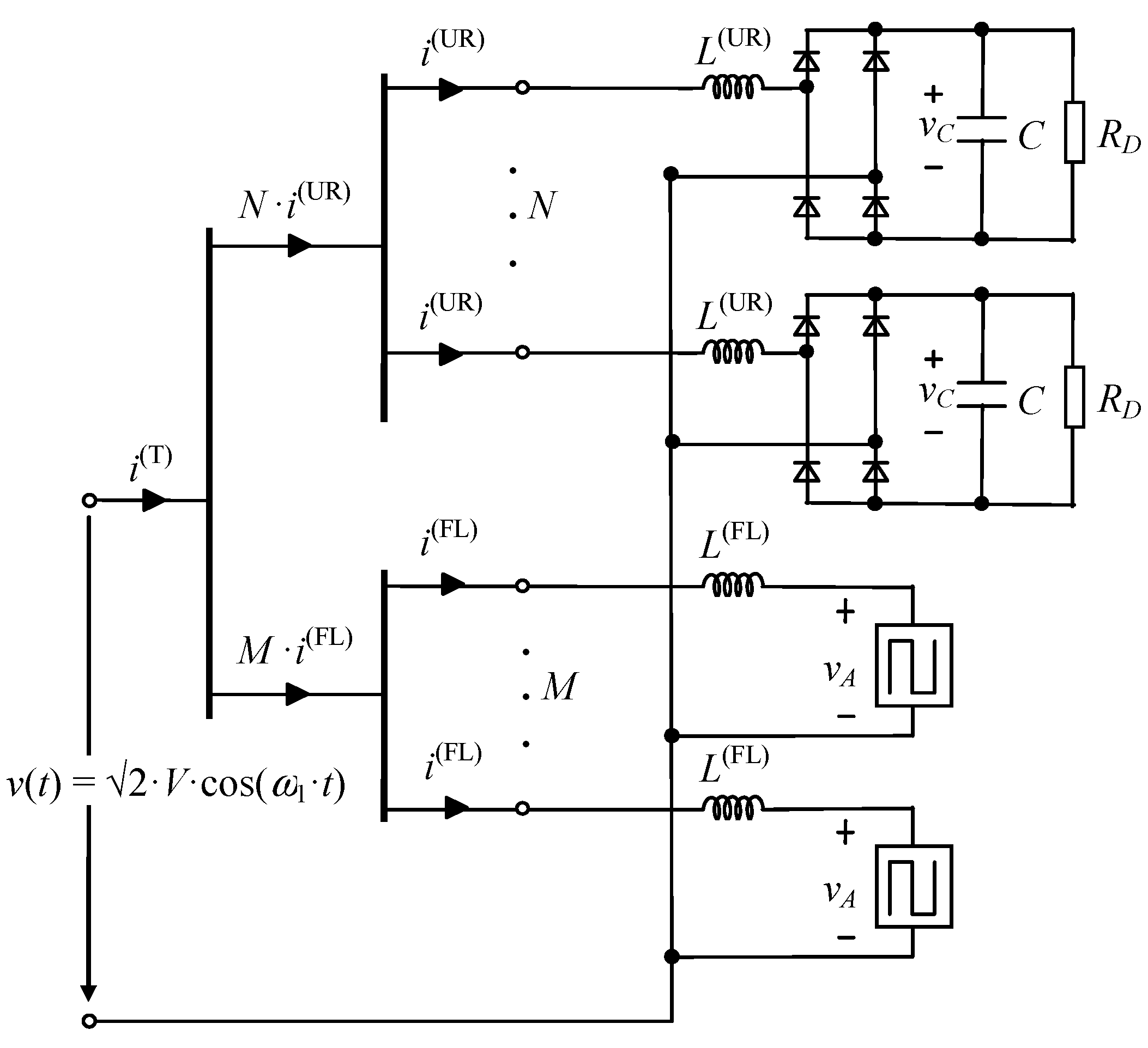
The typical circuits of the single-phase NLLs studied here are presented in Figure 2, where ω1 = 2π·f1, f1 being the fundamental frequency of the supply system. In the UR (representing a power supply of a PC), the resistance, RD, models the DC power consumption [6,7,33]. In the FL (representing a magnetically ballasted lighting device), the arc voltage phenomenon is modeled by the square wave vA = ±VA [42]. The UR and FL characterizations are presented in [41]. Based on a suitable normalization, the behavior of these loads is univocally characterized from normalized parameters. The resistances of the AC side impedances in both NLLs are not considered in this study (i.e., R = 0) because their influence on NLL behavior is much smaller than that of the inductive reactances of these impedances [6,7,33,42]. The normalized parameters, called invariants, are also presented in [43] (UR) and [42] (FL) for the UR and FL, respectively. Their usefulness lies in the fact that they are the minimum number of parameters required to completely characterize NLL behavior. Thus, they can be used to perform studies of NLLs (e.g., harmonic cancellation studies) in a friendly way. The above invariants are presented below.

2.1.1. Single-Phase Uncontrolled Rectifier

Choosing the fundamental supply voltage rms value and the rectifier DC resistance as references (i.e., UR = V1, ZR = RD in Figure 2a, and therefore IR = UR/ZR = V1/RD), the normalized variables iN = i/IR and vC,N = vC/UR can be univocally described only by the UR invariants:
x L , N = X L Z R = L ω 1 R D , x C , N = X C Z R = 1 / ( C ω 1 ) R D ,
and the parameters vk,N = Vk/V1 and βk (k = 1, 3, 5, …) make it possible to consider the harmonic distortion influence on the rectifier behavior.
The usual range of xL,N and xC,N values in practical applications is obtained in [41,43] by relating each one of these invariants to the short-circuit ratio, RSC, at the PCC and the rectifier DC voltage ripple, ∆vC/VC, respectively. Thus, according to [41], their typical values are xL,N (%) = (0.05 … 10) and xC,N (%) = (0.5 … 4.5), which approximately correspond to an RSC = (5 … 1000) and a ∆vC/VC (%) = (1 … 10).

2.1.2. Fluorescent Lamp

Choosing the fundamental supply voltage rms value and the lamp reactance as references (i.e., UR = V1, ZR = XL = L·ω1 in Figure 2b, and therefore IR = UR/ZR = V1/XL), the normalized variable iN = i/IR can be univocally described only by the FL invariant:
v A , N = V A U R = V A V 1 ,
and the parameters vk,N = Vk/V1 and βk (k = 1, 3, 5, …) make it possible to consider the harmonic distortion influence on the lamp behavior.
The usual range of vA,N values in practical applications is obtained in [41,42] by relating this invariant to θ1 (final angle of the positive half-wave of i and initial angle of the negative half-wave of vA). Thus, according to [41], its typical values are vA,N (%) = (0 … 75.9), which correspond to a θ1 (°) = (122.48 … 180) considering the fundamental supply voltage, V1, as a reference (i.e., β1 = 0 in Figure 2).

2.2. Non-Linear Load Fundamental and Harmonic Currents

According to [41], the fundamental and harmonic currents consumed by these NLLs, Ih (h = 1, 3, 5, …), can be easily obtained by multiplying their normalized fundamental and harmonic currents, Ih,N (h = 1, 3, 5, …), by the NLL reference current, IR, i.e.,
I _ h ( UR ) = I R ( UR ) I _ h , N ( UR ) = V 1 R D g _ h ( UR ) ( x L , N , x C , N ) I _ h ( FL ) = I R ( FL ) I _ h , N ( FL ) = V 1 X L g _ h ( FL ) ( v A , N ) ( h = 1 , 3 , 5 , ) ,
where the superscripts (UR) and (FL) denote the single-phase uncontrolled rectifier and the fluorescent lamp, respectively. It must be noted that the normalized fundamental and harmonic currents, Ih,N, are directly related to the NLL invariants. Their influence on these currents is analyzed in [41] from extensive simulations performed by a MATLAB customized program based on (3) considering the typical values of the invariants (Section 2.1.1 and Section 2.1.2) and sinusoidal supply voltages (i.e., vk,N = 0, with k = 3, 5, …).
The UR behavior is analyzed from xL,N and xC,N. It is concluded that the fundamental and harmonic currents are mainly characterized by the invariant xL,N. The FL behavior is analyzed from vA,N. Considering sinusoidal supply voltages, the fundamental and harmonic currents of both loads can be described by the formulae in [44] for the UR and in [45] (model C) for the FL.

3. Power System Model

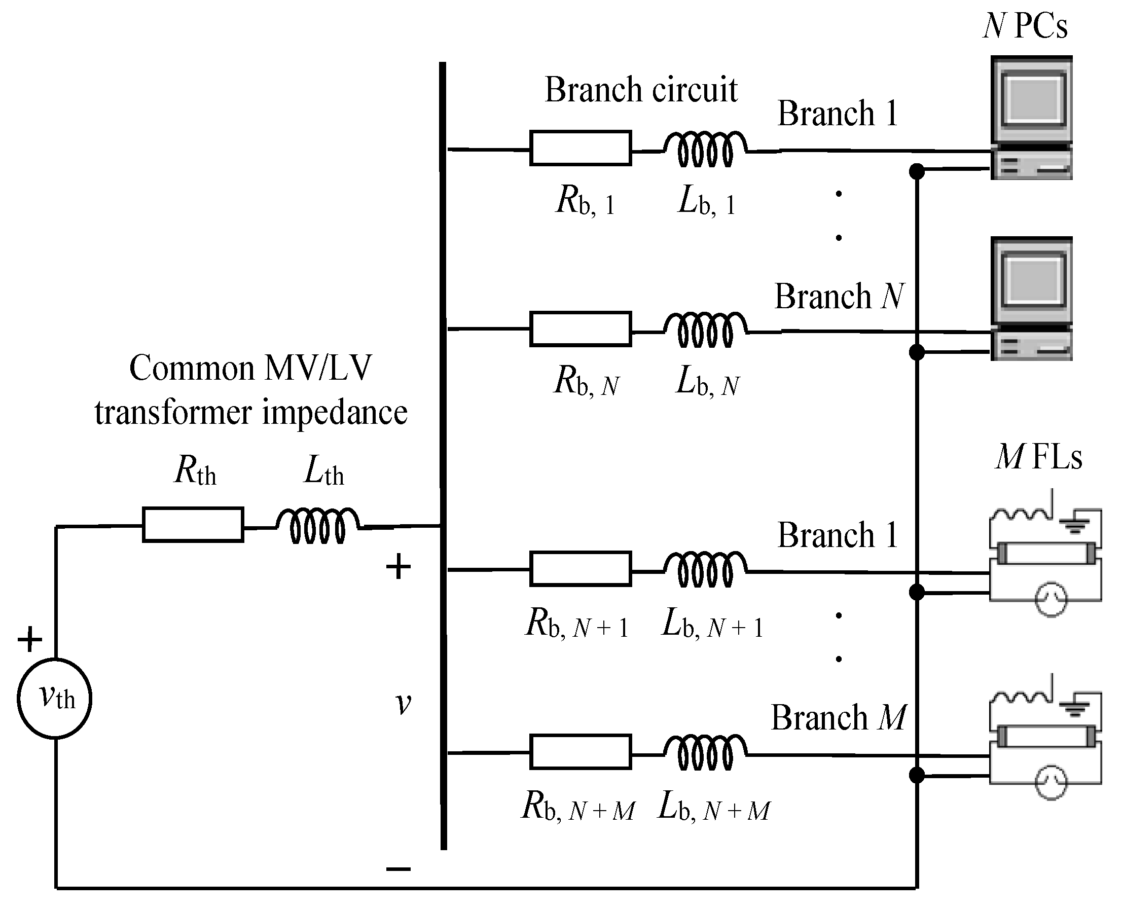
Figure 3 shows the equivalent circuit per phase, including only PCs and FLs, of the typical European commercial installations (circuit also valid for residential installations) in Figure 1. The common MV/LV transformer and the wall outlet circuits are represented by the impedances Zth = Rth + j·Lth·ω1 and Zb,i = Rb,i + j·Lb,i·ω1, respectively, where i = 1, …, N + M. For the cancellation study of the harmonic currents consumed by a set of PCs (URs) and a set of FLs, the following hypotheses are considered:
  • The PC and FL wall outlet circuits are connected to a common stiff bus in parallel supplied by a sinusoidal voltage [6]. The supply voltage assumption is reasonable given the relative independence of harmonic current reduction due to diversity from voltage distortion [7] and the voltage distortion levels in current distribution systems (approximately 2–3%) [41].
  • The wall outlet circuit impedances, Zb,i, are not considered since PC and FL harmonic cancellation mainly depends on the NLL parameters rather than on the branch circuit impedances, Zb,i [7,46].
  • A set of N identical PCs and a set of M identical FLs are considered since harmonic cancellation due to differences in the parameters of the N PCs or of the M FLs is not significant (i.e., the reduction of the total harmonic current consumed by N PCs with different parameters or by M FLs with different parameters is mainly due to the attenuation effect) [7,46].
Thus, the simplified equivalent circuit per phase in Figure 4 is used for the cancellation analysis of the harmonic currents consumed by a set of N identical PCs (URs) and a set of M identical FLs connected at the same voltage level.

4. Cancellation Study of Harmonic Currents

Cancellation of the harmonic currents consumed by a set of N identical PCs (URs) and a set of M identical FLs connected at the same voltage level is analyzed according to Figure 4 and using the models based on the invariants in Section 2. This effect consists of the reduction of the rms value of the total h-th harmonic current consumed by both sets of NLLs together, Ih(T) = |N·Ih(UR) + M·Ih(FL)|, due to the phase angle diversity of the h-th harmonic currents consumed by each of the two sets of NLLs individually, i.e., N·Ih(UR) = N·Ih(UR)ϕh(UR) and M·Ih(FL) = M·Ih(FL))ϕh(FL) for the set of PCs (URs) and the set of FLs, respectively.
The study aims to obtain the values of the NLL invariants (xL,N and xC,N for the URs and vA,N for the FLs) for which this effect is produced. In broad terms, these values can be achieved by determining when the h-th harmonic current phasors of both sets of NLLs are close to counterphase, i.e., when the absolute value of the phase difference of the h-th harmonic current phasors of both sets of NLLs is close to 180° [41]. However, as can be seen in Appendix A, the magnitudes of the h-th harmonic current phasors of both sets of NLLs must also be considered. Therefore, it is better to study cancellation with the diversity factor of the h-th harmonic current (DFh) because it allows the h-th harmonic current reduction due to this effect to be quantified [3,6,8,12,15,17,18,19,20,21,22,23,24,25,26,27,28]. This factor ranges from 0 to 1 (i.e., 0 ≤ DFh (%) ≤ 100), with lower values resulting in higher cancellation levels. Thus, the diversity factor of the h-th harmonic current is expressed as a function of the invariants and the ratio of the power consumption of the set of FLs to total power consumption, i.e., ∆p(FL) = M·P(FL)/(N·P(UR) + M·P(FL)) ∈ ]0, 1[, where P(UR) and P(FL) are the power consumptions of a PC (UR) unit and an FL unit, respectively:
D F h ( x L , N , x C , N , v A , N , Δ p ( FL ) ) = = | N I _ h ( UR ) + M I _ h ( FL ) | N I h ( UR ) + M I h ( FL ) = | I _ h , N ( UR ) + M I R ( FL ) N I R ( UR ) I _ h , N ( FL ) | I h , N ( UR ) + M I R ( FL ) N I R ( UR ) I h , N ( FL ) = | I _ h , N ( UR ) + I _ ˜ h , N ( FL ) | I h , N ( UR ) + I ˜ h , N ( FL ) .
In (4), the UR normalized harmonic currents, Ih,N(UR), are functions of the corresponding invariants, (3), and the FL modified normalized harmonic currents, Ĩh,N(FL), are functions of the corresponding invariants, (3), the FL normalized fundamental current, and the ∆p(FL) ratio:
I R ( FL ) I R ( UR ) = I 1 ( FL ) / I 1 , N ( FL ) V 1 / R D 18 π 2 I 1 , N ( FL ) cos ϕ 1 ( FL ) P ( FL ) P ( UR ) M I R ( FL ) N I R ( UR ) 18 π 2 I 1 , N ( FL ) cos ϕ 1 ( FL ) Δ p ( FL ) 1 Δ p ( FL ) .
The expressions of the power consumptions of a PC (UR) unit and an FL unit, P(UR) = VC2/RD and P(FL) = V1·I1(FL)·cosϕ1(FL), and the approximation of the UR DC voltage mean value VC ≈ (3·√2/π)·V1 [41], are considered in (5). It is important to note that the ∆p(FL) range ]0, 0.5] corresponds to (M·P(FL))/(N·P(UR)) ≤ 1 (i.e., power consumption of the set of PCs is higher than that of the set of FLs), whereas the ∆p(FL) range [0.5, 1[ corresponds to (M·P(FL))/(N·P(UR)) ≥ 1 (i.e., power consumption of the set of PCs is lower than that of the set of FLs).
To assess the global cancellation level of harmonic currents, and as in [47,48] with the attenuation factor, the definition of the diversity factor of the h-th harmonic current, DFh, is extended to a total diversity factor of the harmonic currents, TDF, using the definition of total harmonic distortion, THD, as a reference and considering the weightings of the individual DFh. This total diversity factor can be obtained by calculating a weighted average of the individual DFh, as:
T D F ( x L , N , x C , N , v A , N , Δ p ( FL ) ) = = h = 3 5 , 7 , | N I _ h ( UR ) + M I _ h ( FL ) | 2 h = 3 5 , 7 , ( N I h ( UR ) + M I h ( FL ) ) 2 = h = 3 5 , 7 , | I _ h , N ( UR ) + I _ ˜ h , N ( FL ) | 2 h = 3 5 , 7 , ( I h , N ( UR ) + I ˜ h , N ( FL ) ) 2 = h = 3 5 , 7 , ( w h D F h ) 2 ,
where:
w h = N I h ( UR ) + M I h ( FL ) h = 3 5 , 7 , ( N I h ( UR ) + M I h ( FL ) ) 2 = I h , N ( UR ) + I ˜ h , N ( FL ) h = 3 5 , 7 , ( I h , N ( UR ) + I ˜ h , N ( FL ) ) 2
are the weightings of the individual DFh. It is worth highlighting that the proposed total diversity factor of the harmonic currents can be generalized to any number of sets of multiple identical NLLs, as detailed in Appendix B.

4.1. Graphical Study

In order to analyze the cancellation of the harmonic currents consumed by a set of N identical PCs (URs) and a set of M identical FLs connected at the same voltage level from a graphical point of view, the MATLAB customized program based on (3), which was used to examine the influence of the NLL invariants on the normalized harmonic currents, Ih,N, in [41], was adapted to obtain contour plots of (4) and (6) resulting from setting specific typical values for one of the NLL invariants and the ∆p(FL) ratio, and performing a joint sweep of the other two NLL invariants considering the complete range of their typical values (Section 2.1.1 and Section 2.1.2). In addition, the zones where the diversity factors of the h-th harmonic currents range from 0% to 30%, the absolute values of the phase differences of the h-th harmonic currents range from 150° to 180°, and the magnitude resemblances of the h-th harmonic currents range from 50% to 100%, are also provided by the program and shown for comparison.
Contour plots for h = 3, 5, 7, and 9 in Figure 5 show the diversity factors of the h-th harmonic currents (DFh) and the total diversity factor of the harmonic currents (TDF) as a function of the invariants with the greatest influence on the NLL consumed currents (xL,N and vA,N) and for ∆p(FL) = 70%, 80%, and 90%. In these contour plots, xC,N = 2% since it was numerically verified that the results obtained can be approximately generalized for any value of the invariant xC,N because of its small influence on the UR consumed current. Moreover, values of ∆p(FL) < 70% are not considered in this study because the harmonic cancellation levels associated with them are not significant.
It must be noted that, for any of the ∆p(FL) values and harmonic orders considered, the contour plots in the first four rows of Figure 5 serve to determine the xL,N and vA,N values leading to a specific cancellation level of the individual harmonic currents consumed by a set of URs and a set of FLs. Likewise, given particular xL,N and vA,N values, it is possible to obtain the corresponding cancellation level of the above individual harmonic currents for any of the ∆p(FL) values and harmonic orders considered. Three types of zones are also shown in these plots for comparison: those where the diversity factors of the h-th harmonic currents range from 0% to 30% (i.e., 0 ≤ DFh (%) ≤ 30), those where the absolute values of the phase differences of the h-th harmonic currents range from 150° to 180° (i.e., 150 ≤ Δϕh (°) ≤ 180), and those where the magnitude resemblances of the h-th harmonic currents range from 50% to 100% (i.e., 50 ≤ ΔIh (%) ≤ 100). For the harmonic orders considered, it can be observed that:
  • The zone where 150 ≤ Δϕh (°) ≤ 180 remains unchanged when Δp(FL) varies, covering the whole range of xL,N. On the other hand, the whole range of vA,N is covered by this zone only for the seventh and ninth harmonic orders.
  • The zone where 50 ≤ ΔIh (%) ≤ 100 covers the whole range of vA,N and moves from high values of xL,N to low values when Δp(FL) increases.
  • Practically the whole zone where 0 ≤ DFh (%) ≤ 30 is contained in the intersection of the two previous zones in all the plots. Therefore, like the zone where 50 ≤ ΔIh (%) ≤ 100, it moves from high to low values of xL,N when Δp(FL) increases.
If the aim is to assess the global cancellation level of harmonic currents, the TDF is the proposed index. Thus, for any of the Δp(FL) values considered, the contour plots in the fifth row of Figure 5 make it possible to determine the xL,N and vA,N values leading to a specific global cancellation level of the harmonic currents consumed by a set of URs and a set of FLs. Likewise, given particular xL,N and vA,N values, it is possible to obtain the corresponding global cancellation level of the above harmonic currents for any of the Δp(FL) values considered. It can be observed that, like the zones where 50 ≤ ΔIh (%) ≤ 100 and 0 ≤ DFh (%) ≤ 30 for the harmonic orders studied, the zone with the lowest TDF moves from high to low values of xL,N when Δp(FL) increases.
The contour plots of the TDF globally summarize, in a weighted manner, what is observed in the contour plots of the individual DFh for the harmonic orders h = 3, 5, 7, and 9, both for any of the Δp(FL) values considered and when Δp(FL) increases. Therefore, the suitability of the TDF to assess the global cancellation level of harmonic currents, simultaneously taking into account their magnitudes and phase angles, has been graphically checked for a set of N identical PCs (URs) and a set of M identical FLs connected at the same voltage level.

4.2. Optimization Study

Considering the power ranges for a PC (UR) unit (100–300 W) and an FL unit (15–80 W) in Section 1, this study aims to find the values of their respective invariants, as well as the M/N ratio range, in order to maximize the global cancellation level of the harmonic currents consumed by a set of N identical PCs (URs) and a set of M identical FLs connected at the same voltage level. To that end, the MATLAB program used in Section 4.1 is simplified to provide values of (4) and (6) as a result of setting specific values for the NLL invariants and the Δp(FL) ratio. The resulting program is a MATLAB function that will be passed as an argument to the global optimization numerical method ECAM [49] supplied by the MATLAB version of the GANSO programming library [50].
The GANSO library implements a number of Global And Non-Smooth Optimization methods that can solve the generic optimization problem:
min f ( x ) s . t . x D n
The feasible domain, D, is specified by a number of linear constraints (equations and inequalities), including box constraints. In the case of unconstrained minimization, D = n . Differentiability of the objective function, f, is not assumed, and only Lipschitz continuity (local or global) is required, i.e.,
| f ( x ) f ( y ) | L d ( x , y ) ,
where x and y are two points in D, d(x, y) is the distance between these points, and L is a positive number. The inequality should hold for all x, yD. Under such a general condition, the optimization problem is extremely difficult. The objective function may have many local extrema, and locating its global minimum is very challenging.
Under the Lipschitz continuity assumption, it is possible to estimate the smallest possible minimum of the objective function from its recorded values at various points. It follows from the Lipschitz condition that:
f ( x ) max k = 1 , , K { f ( x k ) L d ( x k , x ) } = H ( x ) ,
where xk are the points with the recorded values of f(xk), and L is the Lipschitz constant of f. The expression on the right is called the (saw-tooth) underestimate of f. By using a large number of points, xk, it is possible to approximate f closely by its underestimate H, and then use the global minimum of the underestimate to approximate that of f. It turns out that minimizing the underestimate H is a structured optimization problem, and all its local (and hence global) minimizers can be explicitly found. This is the basis of the Extended Cutting Angle Method (ECAM), which uses a computationally efficient representation of local minimizers of H in a tree data structure and computes the global minimum of f from this information. The method guarantees the globally optimal solution.
In order to analyze the cancellation of the harmonic currents consumed by a set of N identical PCs (URs) and a set of M identical FLs connected at the same voltage level from an optimization point of view, five optimization problems are of interest:
min D F h ( x L , N , x C , N , v A , N , Δ p ( FL ) ) ( h = 3 , 5 , 7 , 9 ) s . t . ( x L , N , x C , N , v A , N , Δ p ( FL ) ) D min T D F ( x L , N , x C , N , v A , N , Δ p ( FL ) ) s . t . ( x L , N , x C , N , v A , N , Δ p ( FL ) ) D
For the five optimization problems, D = [0.05 … 10, 0.5 … 4.5, 0 … 75.9, 5 … 95]% is the feasible domain specified by four box constraints.
As justifiably assumed in Section 4.1, xC,N = 2%, enabling the five optimization problems to be reformulated as follows:
min D F h ( x L , N , v A , N , Δ p ( FL ) ) ( h = 3 , 5 , 7 , 9 ) s . t . ( x L , N , v A , N , Δ p ( FL ) ) D min T D F ( x L , N , v A , N , Δ p ( FL ) ) s . t . ( x L , N , v A , N , Δ p ( FL ) ) D
For the five reformulated optimization problems, D = [0.05 … 10, 0 … 75.9, 5 … 95]% is the feasible domain specified by three box constraints.
The optimal objective function values (min) and the optimal arguments (arg min) of the five reformulated optimization problems are obtained by applying ECAM with a starting point located in the center of the feasible domain, an estimate of the Lipschitz constant of the objective function equal to 10000, and a maximum number of iterations equal to 5000.
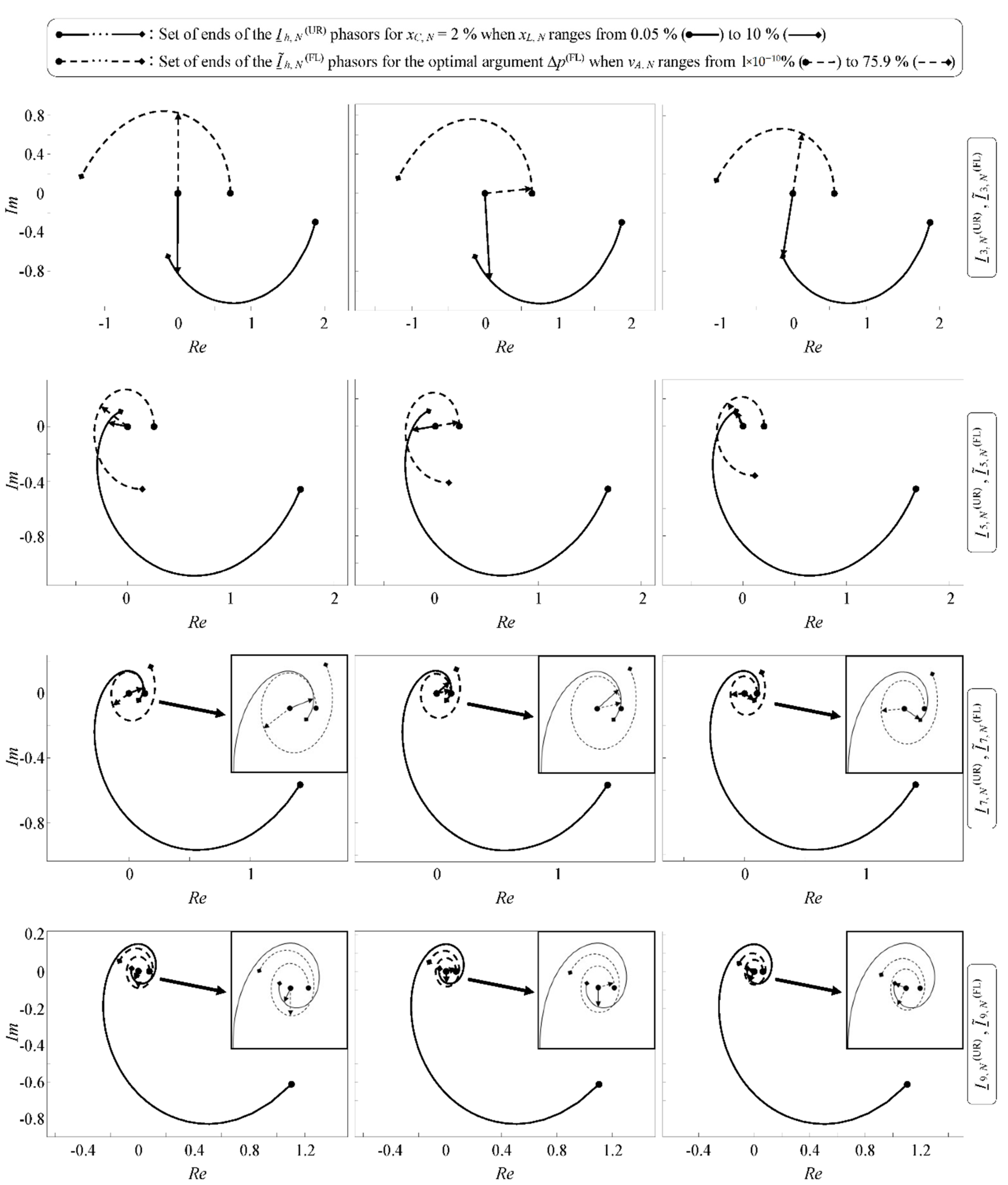
Phasorial plots for h = 3, 5, 7, and 9 in Figure 6 and Figure 7 show the Ih,N(UR) phasors for xC,N = 2% and the optimal argument xL,N, and the Ĩh,N (FL) phasors for the optimal arguments vA,N and Δp(FL), associated with the five reformulated optimization problems. In addition, the sets of ends of the Ih,N(UR) phasors for xC,N = 2% and the usual range of xL,N values, and the sets of ends of the Ĩh,N(FL) phasors for the optimal argument Δp(FL) and the usual range of vA,N values, are also depicted to show where the Ih,N(UR) and Ĩh,N(FL) phasors associated with the optima are located within the sets of feasible Ih,N(UR) and Ĩh,N(FL) phasors, respectively. A zoomed-in view of the zone of interest is provided in some phasorial plots of Figure 6 and Figure 7 for easy viewing. The phasorial plots associated with the reformulated optimization problem min TDF are shown in the right column for comfortable comparison with those associated with the other reformulated optimization problems in the left and central columns.
The optimal objective function values and the optimal arguments, the latter associated with the Ih,N(UR) and Ĩh,N(FL) phasors in Figure 6 and Figure 7, were obtained by applying ECAM to solve the different reformulated optimization problems and are provided in Table 2. The diversity factors of the h-th harmonic currents (DFh) and the total diversity factor of the harmonic currents (TDF) associated with the optima of the different reformulated optimization problems are presented in Table 3.
From the above, it can be deduced that:
  • The higher the harmonic order, h, the lower the optimal argument Δp(FL) and the shorter the Ĩh,N(FL) phasors associated with the optimum of the corresponding reformulated optimization problem min DFh. These shorter Ĩh,N(FL) phasors are located within sets of also shorter feasible Ĩh,N(FL) phasors.
  • Total cancellation of any of the h-th harmonic currents considered in the study is possible, but total global cancellation of all of them is impossible.
  • Only total cancellation of the third or seventh harmonic currents leads to high global cancellation of the harmonic currents.
  • High cancellations of the third and seventh harmonic currents, with higher cancellation of the harmonic current with the lowest harmonic order, lead to the highest global cancellation of the harmonic currents.
  • Total cancellation of any of the h-th harmonic currents considered in the study does not imply the highest global cancellation of the harmonic currents.
  • The highest global cancellation of the harmonic currents does not imply total cancellation of any of the h-th harmonic currents considered in the study.
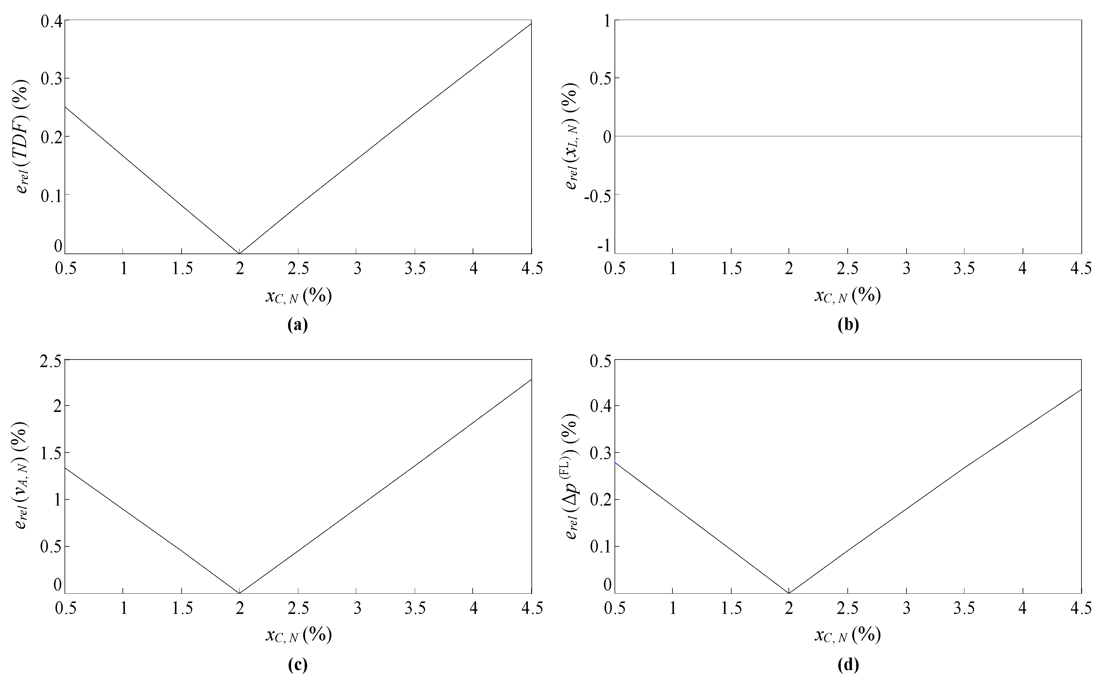
The optimal objective function value and the optimal arguments enabling the global cancellation level of the harmonic currents consumed by a set of N identical PCs (URs) and a set of M identical FLs connected at the same voltage level to be maximized, i.e., those obtained by solving the fifth reformulated optimization problem of (12) and shown in the last row of Table 2, must be compared for accuracy with those obtained by solving the fifth optimization problem of (11) before being used in further studies. This can be seen from Figure 8, where the relative errors of the fifth reformulated optimization problem of (12) with respect to the fifth optimization problem of (11) not only in the optimal objective function value but also in the optimal arguments are plotted. With a maximum value of relative error below 2.5%, a value associated with only one of the optimal arguments, it can be said that the optimal objective function value and the optimal arguments shown in the last row of Table 2 are accurate enough. This means that, according to the power ranges in Section 1 for a PC (UR) unit (100–300 W) and an FL unit (15–80 W), the optimal argument Δp(FL) = 73.58% can be used to determine the optimal M/N ratio range for a set of N identical PCs (URs) with xL,N = 10% and xC,N ∈ [0.5, 4.5]% and a set of M identical FLs with vA,N = 39.74% connected at the same voltage level. The expressions in (5) lead to:
M N Δ p ( FL ) 1 Δ p ( FL ) P ( UR ) P ( FL ) .
According to interval arithmetic, the lower bound of the optimal M/N ratio range is obtained from (13) by using the lower bound of the power range for a PC (UR) unit and the upper bound of the power range for an FL unit, i.e., the lowest feasible P(UR)/P(FL) ratio. Likewise, the upper bound of the optimal M/N ratio range is obtained from (13) by using the upper bound of the power range for a PC (UR) unit and the lower bound of the power range for an FL unit, i.e., the highest feasible P(UR)/P(FL) ratio. Thus, the resulting optimal M/N ratio range is [3.4, 55.8] = [17/5, 279/5]. From a practical point of view, this means that, for the lowest feasible P(UR)/P(FL) ratio, every set of 5 identical PCs (URs) with xL,N = 10% and xC,N ∈ [0.5, 4.5]% must be connected at the same voltage level to a set of 17 identical FLs with vA,N = 39.74% in order to achieve the highest global cancellation of the harmonic currents. Likewise, for the highest feasible P(UR)/P(FL) ratio, every set of 5 identical PCs (URs) with xL,N = 10% and xC,N ∈ [0.5, 4.5]% must be connected at the same voltage level to a set of 279 identical FLs with vA,N = 39.74% in order to achieve the highest global cancellation of the harmonic currents. For other feasible P(UR)/P(FL) ratios, the corresponding optimal M/N ratios are also obtained from (13), e.g., a P(UR)/P(FL) ratio of 200/30 W leads to an optimal M/N ratio of 18.6 = 93/5, and obviously 18.6 ∈ [3.4, 55.8], i.e., 93/5 ∈ [17/5, 279/5]. As can be seen, the usefulness of the TDF to assess the global cancellation level of harmonic currents considering their magnitudes and phase angles simultaneously has been checked by applying it to the optimization study developed in this section.

5. Some Remarks on the Performed Cancellation Study

It can be seen that the two types of loads connected at the same voltage level have different harmonic profiles, which is why there is a real possibility of cancellation of their corresponding harmonic currents. The harmonic cancellation effect is a reduction of the harmonic currents owing to their phase angle diversity. The diversity factor allows the reduction due to this effect to be quantified. The study carried out in this paper reveals that only two different types of loads connected at the same voltage level are enough to have such a phase angle diversity that it leads to low values of the diversity factor, i.e., to high levels of cancellation (see Table 2 and Table 3). More than two different types of loads connected at the same voltage level would increase the phase angle diversity, but this would not necessarily lead to lower values of the diversity factor, i.e., to higher levels of cancellation. On the other hand, there are other types of loads with both higher powers and much more different harmonic profiles compared to those of the types of loads studied, which would increase the harmonic cancellation impact when connected at the same voltage level.
A set of multiple identical PCs and a set of multiple identical FLs have been considered, when in fact there is a wide variety of each of these types of loads with quite different harmonic spectra on the market. The specific PC studied corresponds to the typical single-phase capacitive rectifier without active filtering stages, and the specific FL studied corresponds to the typical FL with an arc voltage modeled by a square wave and with a magnetic ballast (see their respective circuits in Figure 2). The choice of these two specific loads is because their modeling is well-known in the literature, which has allowed a better study of the problem and of the application of the proposed index to be performed. It is true that there is no cancellation of harmonic currents between the multiple PCs of the set because they are identical, and the same occurs with the multiple FLs of the other set. However, there is a cancellation of harmonic currents between both sets of loads because their loads are of different types and of different harmonic profiles. If it were of interest to carry out a cancellation study of harmonic currents between two loads of a specific type with quite different harmonic spectra, each of these two loads could be included in a different set (two sets in total), enabling this cancellation study to be performed in a similar way as has been carried out in this paper.
The emission of harmonic currents from a non-linear load depends on many factors. Some of the factors have been considered in the models and in the optimization, while other factors have not been considered in a justified way so as not to complicate the cancellation study, although without loss of generality. Thus, the type of rectifier circuit and its topology have been contemplated in the non-linear load model used, and in its parameters, although other types of rectifier circuits and their topologies could have been considered. The type of power system has been contemplated in the power system model used, and in its parameters, carrying out some justified simplifications on it, although other types of power systems could have been considered. The presence of voltages with harmonic distortions in the power system has not been contemplated because the limits imposed by the standards allow stating that in general, these distortions will not be high, being at most 3% in current power systems, as indicated in Section 3. However, the presence of voltages with harmonic distortions in the power system could have been considered. In summary, the models and the optimization explicitly or implicitly consider some of the factors that can affect the cancellation of harmonic currents, while the non-consideration of other factors is justifiably performed. It is true that a more complete study could have been carried out in terms of types of loads, types of power systems, and the presence of voltages with harmonic distortions, but this does not detract from the generality of the cancellation study of harmonic currents presented in this paper.

6. Conclusions

With the purpose of assessing the global cancellation level of harmonic currents considering their magnitudes and phase angles simultaneously from a single index, an appropriate index was proposed. This index is an extension of the definition of the diversity factor of the h-th harmonic current, DFh, to a total diversity factor of the harmonic currents, TDF, by using the definition of total harmonic distortion, THD, as a reference and considering the weightings of the individual DFh. After simplifying the equivalent circuit per phase of the typical three-phase power system of European commercial installations, the TDF was applied to the cancellation study of the harmonic currents consumed by a set of N identical PCs (URs) and a set of M identical FLs connected at the same voltage level. In view of the results obtained and discussed in Section 4 and Section 5, it can be concluded that:
  • The TDF globally summarizes, in a weighted manner, what the individual DFh indicate, demonstrating the suitability of the TDF.
  • By using a global optimization numerical method such as ECAM, the TDF can be used to find optimal values of the UR and FL invariants, as well as optimal M/N ratios, which is of interest from a practical point of view. The optimization study that made it possible to obtain them demonstrates the usefulness of the TDF.
Since the TDF can be generalized to any number of sets of multiple identical NLLs, future work could extend the cancellation study of harmonic currents presented in this paper not only to other pairs of sets of multiple identical NLLs, but also to more than two such sets connected at the same voltage level. It is also proposed as future work to analyze how factors such as other types of rectifier circuits and their topologies different from that considered in this paper, other types of power systems different from that contemplated in this paper, and the presence of voltages with harmonic distortions in the power systems, influence the TDF.

Author Contributions

Conceptualization, J.J.M. and L.S.; methodology, L.S. and J.P.; software and validation, J.J.M. and L.M.; writing—original draft preparation, J.J.M. and L.S.; writing—review and editing, J.J.M. All authors have read and agreed to the published version of the manuscript.

Funding

This research was funded by the Ministerio de Ciencia, Innovación y Universidades, under Grant RTI2018-095720-B-C33.

Institutional Review Board Statement

Not applicable.

Informed Consent Statement

Not applicable.

Data Availability Statement

Not applicable.

Conflicts of Interest

The authors declare no conflict of interest.

Appendix A. Cancellation of the Harmonic Currents

It is commonly accepted that a high cancellation level of the h-th harmonic current occurs when two h-th harmonic current phasors (Ih(1) = Ih(1)ϕh(1) and Ih(2) = Ih(2))ϕh(2)) are close to counterphase (i.e., when the absolute value of the phase difference of two h-th harmonic current phasors is close to 180°). As a result, their geometric sum is much smaller than their arithmetic sum. Nevertheless, the magnitudes of the two h-th harmonic current phasors also influence their geometric sum, which must be considered in harmonic cancellation studies. To explore this influence, the diversity factor of the h-th harmonic current is written as a function of Δϕh = |ϕh(1)ϕh(2)| (Δϕh allows the absolute value of the phase difference of two h-th harmonic current phasors to be determined) and ΔIh = min{Ih(1), Ih(2)}/max{Ih(1), Ih(2)} (ΔIh allows the magnitude resemblance of two h-th harmonic current phasors to be determined):
D F h ( Δ ϕ h , Δ I h ) = | I _ h ( 1 ) + I _ h ( 2 ) | I h ( 1 ) + I h ( 2 ) = 1 + ( Δ I h ) 2 + 2 Δ I h cos ( Δ ϕ h ) 1 + Δ I h .
Figure A1a shows (A1) in a contour plot. It can be observed that two h-th harmonic current phasors far from counterphase (point B and plot B in Figure A1a and Figure A1b, respectively) may lead to a higher cancellation level than two h-th harmonic current phasors close to counterphase (point A and plot A in Figure A1a and Figure A1b, respectively). Therefore, to achieve a high cancellation level of the h-th harmonic current, not only must the two h-th harmonic current phasors be close to counterphase, but their magnitudes must also be very similar (point C and plot C in Figure A1a and Figure A1b, respectively).
Figure A1. Cancellation of two h-th harmonic current phasors Ih(1) = Ih(1)ϕh(1) and Ih(2) = Ih(2)ϕh(2): (a) Diversity factor of the h-th harmonic current (DFh) as a function of Δϕh = |ϕh(1)ϕh(2)| and ΔIh = min{Ih(1), Ih(2)}/max{Ih(1), Ih(2)}. (b) Phasorial diagrams at three specific points.
Energies 15 04315 g0a1

Appendix B. Generalization of the Total Diversity Factor of the Harmonic Currents

Suppose that it is of interest to analyze the cancellation of the harmonic currents consumed by a set of N identical NLL1s, a set of M1 identical NLL2s, …, and a set of Mn−1 identical NLLns connected at the same voltage level. This effect consists of the reduction of the rms value of the total h-th harmonic current consumed by all the n sets of NLLs together, Ih(T) = |N·Ih(NLL1) + M1·Ih(NLL2) + ⋯⋯ + Mn−1·Ih(NLLn)|, due to the phase angle diversity of the h-th harmonic currents consumed by each of the n sets of NLLs individually, i.e., N·Ih(NLL1) = N·Ih(NLL1)ϕh(NLL1), M1·Ih(NLL2) = M1·Ih(NLL2)ϕh(NLL2), …, and Mn−1·Ih(NLLn) = Mn−1·Ih(NLLn)ϕh(NLLn) for the set of NLL1s, the set of NLL2s, …, and the set of NLLns, respectively.
It is convenient to study the cancellation with the diversity factor of the h-th harmonic current (DFh), because it allows the h-th harmonic current reduction due to this effect to be quantified [3,6,8,12,15,17,18,19,20,21,22,23,24,25,26,27,28]. This factor ranges from 0 to 1 (i.e., 0 ≤ DFh (%) ≤ 100), with lower values resulting in higher cancellation levels. Thus, the diversity factor of the h-th harmonic current is expressed as a function of the invariants p1,N, …, pm,N and the ratios of the power consumptions of the sets of NLL2s, …, NLLns to total power consumption, i.e., ∆p(NLL2) = M1·P(NLL2)/(N·P(NLL1) + M1·P(NLL2) + ··· + Mn−1·P(NLLn)) ∈ ]0, 1[, …, ∆p(NLLn) = Mn−1·P(NLLn)/(N·P(NLL1) + M1·P(NLL2) + ··· + Mn−1·P(NLLn)) ∈ ]0, 1[, where P(NLL1), P(NLL2), …, and P(NLLn) are the power consumptions of an NLL1 unit, an NLL2 unit, …, and an NLLn unit, respectively:
D F h ( p 1 , N , , p m , N , Δ p ( NLL 2 ) , , Δ p ( NLL n ) ) = | N I _ h ( NLL 1 ) + M 1 I _ h ( NLL 2 ) + + M n 1 I _ h ( NLL n ) | N I h ( NLL 1 ) + M 1 I h ( NLL 2 ) + + M n 1 I h ( NLL n ) = | I _ h , N ( NLL 1 ) + M 1 I R ( NLL 2 ) N I R ( NLL 1 ) I _ h , N ( NLL 2 ) + + M n 1 I R ( NLL n ) N I R ( NLL 1 ) I _ h , N ( NLL n ) | I h , N ( NLL 1 ) + M 1 I R ( NLL 2 ) N I R ( NLL 1 ) I h , N ( NLL 2 ) + + M n 1 I R ( NLL n ) N I R ( NLL 1 ) I h , N ( NLL n ) = | I _ h , N ( NLL 1 ) + I _ ˜ h , N ( NLL 2 ) + + I _ ˜ h , N ( NLL n ) | I h , N ( NLL 1 ) + I ˜ h , N ( NLL 2 ) + + I ˜ h , N ( NLL n ) .
In (A2), the NLL1 normalized harmonic currents, Ih,N(NLL1), are functions of the corresponding invariants, and the NLLi modified normalized harmonic currents, Ĩh,N(NLLi), are functions of at least the corresponding invariants and the corresponding ∆p(NLLi) ratio. It is important to note that the ∆p(NLLi) range ]0, 0.5] corresponds to (Mi−1·P(NLLi))/(N·P(NLL1)) ≤ 1 (i.e., power consumption of the set of NLL1s is higher than that of the set of NLLis), whereas the ∆p(NLLi) range [0.5, 1[ corresponds to (Mi−1·P(NLLi))/(N·P(NLL1)) ≥ 1 (i.e., power consumption of the set of NLL1s is lower than that of the set of NLLis).
To assess the global cancellation level of harmonic currents, and as in [47,48] with the attenuation factor, the definition of the diversity factor of the h-th harmonic current, DFh, is extended to a total diversity factor of the harmonic currents, TDF, using the definition of total harmonic distortion, THD, as a reference and considering the weightings of the individual DFh. This total diversity factor can be obtained by calculating a weighted average of the individual DFh, as:
T D F ( p 1 , N , , p m , N , Δ p ( NLL 2 ) , , Δ p ( NLL n ) ) = h = 3 5 , 7 , | N I _ h ( NLL 1 ) + M 1 I _ h ( NLL 2 ) + + M n 1 I _ h ( NLL n ) | 2 h = 3 5 , 7 , ( N I h ( NLL 1 ) + M 1 I h ( NLL 2 ) + + M n 1 I h ( NLL n ) ) 2 = h = 3 5 , 7 , | I _ h , N ( NLL 1 ) + I _ ˜ h , N ( NLL 2 ) + + I _ ˜ h , N ( NLL n ) | 2 h = 3 5 , 7 , ( I h , N ( NLL 1 ) + I ˜ h , N ( NLL 2 ) + + I ˜ h , N ( NLL n ) ) 2 = h = 3 5 , 7 , ( w h D F h ) 2 ,
where:
w h = N I h ( NLL 1 ) + M 1 I h ( NLL 2 ) + + M n 1 I h ( NLL n ) h = 3 5 , 7 , ( N I h ( NLL 1 ) + M 1 I h ( NLL 2 ) + + M n 1 I h ( NLL n ) ) 2 = I h , N ( NLL 1 ) + I ˜ h , N ( NLL 2 ) + + I ˜ h , N ( NLL n ) h = 3 5 , 7 , ( I h , N ( NLL 1 ) + I ˜ h , N ( NLL 2 ) + + I ˜ h , N ( NLL n ) ) 2
are the weightings of the individual DFh.

References

  1. Teixeira, M.D.; de Oliveira, J.C.; Medeiros, C.A.G.; de Oliveira, J.C.; Teixeira, G.S. A Power Quality Comparative Analysis Related to Electronic and Electromagnetic Fluorescent Ballast Operation. In Proceedings of the 10th IEEE International Conference on Harmonics and Quality of Power (ICHQP), Rio de Janeiro, Brazil, 6–9 October 2002; pp. 424–429. [Google Scholar]
  2. Emanuel, A.E.; Janczak, J.; Pileggi, D.J.; Gulachenski, E.M.; Breen, M.; Gentile, T.J.; Sorensen, D. Distribution feeders with nonlinear loads in the northeast U.S.A.: Part I—Voltage distortion forecast. IEEE Trans. Power Deliv. 1995, 10, 340–347. [Google Scholar] [CrossRef]
  3. Mansoor, A.; Grady, W.M. Analysis of Compensation Factors Influencing the Net Harmonic Current Produced by Single-Phase Non-Linear Loads. In Proceedings of the 8th IEEE International Conference on Harmonics and Quality of Power (ICHQP), Athens, Greece, 14–16 October 1998; pp. 883–889. [Google Scholar]
  4. Mansoor, A. Lower Order Harmonic Cancellation: Impact of Low-Voltage Network Topology. In Proceedings of the IEEE Power Engineering Society Winter Meeting (PESWM), New York, NY, USA, 31 January–4 February 1999; pp. 1106–1109. [Google Scholar]
  5. Ngandui, É.; Paraiso, D. Line and Neutral Current Harmonics Characteristics in Three-Phase Computer Power Systems. In Proceedings of the IEEE Canadian Conference on Electrical and Computer Engineering (CCECE), Niagara Falls, ON, Canada, 2–5 May 2004; pp. 1659–1664. [Google Scholar]
  6. Mansoor, A.; Grady, W.M.; Chowdhury, A.H.; Samotyj, M.J. An investigation of harmonics attenuation and diversity among distributed single-phase power electronic loads. IEEE Trans. Power Deliv. 1995, 10, 467–473. [Google Scholar] [CrossRef]
  7. Mansoor, A.; Grady, W.M.; Staats, P.T.; Thallam, R.S.; Doyle, M.T.; Samotyj, M.J. Predicting the net harmonic currents produced by large numbers of distributed single-phase computer loads. IEEE Trans. Power Deliv. 1995, 10, 2001–2006. [Google Scholar] [CrossRef]
  8. Grady, W.M.; Mansoor, A.; Fuchs, E.F.; Verde, P.; Doyle, M. Estimating the Net Harmonic Currents Produced by Selected Distributed Single-Phase Loads: Computers, Televisions, and Incandescent Light Dimmers. In Proceedings of the IEEE Power Engineering Society Winter Meeting (PESWM), New York, NY, USA, 27–31 January 2002; pp. 1090–1094. [Google Scholar]
  9. Moore, P.J.; Portugués, I.E. The influence of personal computer processing modes on line current harmonics. IEEE Trans. Power Deliv. 2003, 18, 1363–1368. [Google Scholar] [CrossRef]
  10. Hansen, S.; Nielsen, P.; Blaabjerg, F. Harmonic cancellation by mixing nonlinear single-phase and three-phase loads. IEEE Trans. Ind. Appl. 2000, 36, 152–159. [Google Scholar] [CrossRef]
  11. Capasso, A.; Lamedica, R.; Prudenzi, A. Estimation of Net Harmonic Currents Due to Dispersed Non-Linear Loads within Residential Areas. In Proceedings of the 8th IEEE International Conference on Harmonics and Quality of Power (ICHQP), Athens, Greece, 14–16 October 1998; pp. 700–705. [Google Scholar]
  12. El-Saadany, E.F.; Salama, M.M.A. Reduction of the net harmonic current produced by single-phase non-linear loads due to attenuation and diversity effects. Int. J. Electr. Power Energy Syst. 1998, 20, 259–268. [Google Scholar] [CrossRef]
  13. Nassif, A.B.; Acharya, J. An Investigation on the Harmonic Attenuation Effect of Modern Compact Fluorescent Lamps. In Proceedings of the 13th IEEE International Conference on Harmonics and Quality of Power (ICHQP), Wollongong, NSW, Australia, 28 September–1 October 2008; pp. 1–6. [Google Scholar]
  14. Elhenawy, A.A.E.; Sayed, M.M.; Gilany, M.I. Harmonic Cancellation in Residential Buildings. In Proceedings of the 20th International Middle East Power Systems Conference (MEPCON), Cairo, Egypt, 18–20 December 2018; pp. 346–351. [Google Scholar]
  15. Mesas, J.J.; Sainz, L.; Sala, P. Statistical study of personal computer cluster harmonic currents from experimental measurements. Electr. Power Compon. Syst. 2015, 43, 56–68. [Google Scholar] [CrossRef] [Green Version]
  16. Rawa, M.J.H.; Thomas, D.W.P.; Sumner, M. Harmonics Attenuation of Nonlinear Loads Due to Linear Loads. In Proceedings of the IEEE Asia-Pacific Symposium on Electromagnetic Compatibility (APEMC), Singapore, 21–24 May 2012; pp. 829–832. [Google Scholar]
  17. Meyer, J.; Schegner, P.; Heidenreich, K. Harmonic Summation Effects of Modern Lamp Technologies and Small Electronic Household Equipment. In Proceedings of the 21st International Conference on Electricity Distribution (CIRED), Frankfurt, Germany, 6–9 June 2011; Paper 0755. pp. 1–4. [Google Scholar]
  18. Ćuk, V.; Cobben, J.F.G.; Kling, W.L.; Ribeiro, P.F. Analysis of harmonic current summation based on field measurements. IET Gener. Transm. Distrib. 2013, 7, 1391–1400. [Google Scholar] [CrossRef]
  19. Blanco, A.M.; Meyer, J.; Schegner, P. Calculation of Phase Angle Diversity for Time-Varying Harmonic Currents from Grid Measurement. In Proceedings of the 12th EA4EPQ International Conference on Renewable Energies and Power Quality (ICREPQ), Córdoba, Spain, 8–10 April 2014; pp. 790–795. [Google Scholar]
  20. Ahmed, E.E.; Xu, W.; Zhang, G. Analyzing systems with distributed harmonic sources including the attenuation and diversity effects. IEEE Trans. Power Deliv. 2005, 20, 2602–2612. [Google Scholar] [CrossRef]
  21. Ćuk, V.; Cobben, J.F.G.; Kling, W.L.; Timens, R.B. An Analysis of Diversity Factors Applied to Harmonic Emission Limits for Energy Saving Lamps. In Proceedings of the 14th IEEE International Conference on Harmonics and Quality of Power (ICHQP), Bergamo, Italy, 26–29 September 2010; pp. 1–6. [Google Scholar]
  22. Suárez, J.A.; Di Mauro, G.F.; Anaut, D.; Agüero, C. Análisis de la distorsión armónica y los efectos de atenuación y diversidad en áreas residenciales. IEEE Lat. Am. Trans. 2005, 3, 429–435. [Google Scholar]
  23. Hegazy, Y.G.; Salama, M.M.A. Calculations of diversified harmonic currents in electric distribution systems. IEE Proc.—Gener. Transm. Distrib. 2003, 150, 651–658. [Google Scholar] [CrossRef]
  24. Hegazy, Y.G.; Salama, M.M.A. Calculations of Diversified Harmonic Currents in Multiple Converter Systems. In Proceedings of the IEEE Power Engineering Society Summer Meeting (PESSM), Seattle, WA, USA, 16–20 July 2000; pp. 727–731. [Google Scholar]
  25. Djokic, S.Z.; Collin, A.J. Cancellation and Attenuation of Harmonics in Low Voltage Networks. In Proceedings of the 16th IEEE International Conference on Harmonics and Quality of Power (ICHQP), Bucharest, Romania, 25–28 May 2014; pp. 137–141. [Google Scholar]
  26. Collin, A.J.; Cresswell, C.E.; Djokic, S.Z. Harmonic Cancellation of Modern Switch-Mode Power Supply Load. In Proceedings of the 14th IEEE International Conference on Harmonics and Quality of Power (ICHQP), Bergamo, Italy, 26–29 September 2010; pp. 1–9. [Google Scholar]
  27. Collin, A.J.; Djokic, S.Z.; Cresswell, C.E.; Blanco, A.M.; Meyer, J. Cancellation of Harmonics between Groups of Modern Compact Fluorescent Lamps. In Proceedings of the International Symposium on Power Electronics, Electrical Drives, Automation and Motion (SPEEDAM), Ischia, Italy, 18–20 June 2014; pp. 1190–1194. [Google Scholar]
  28. Blanco, A.M.; Stiegler, R.; Meyer, J. Power Quality Disturbances Caused by Modern Lighting Equipment (CFL and LED). In Proceedings of the IEEE Power Tech Conference (PTC), Grenoble, France, 16–20 June 2013; pp. 1–6. [Google Scholar]
  29. Eisenmann III, F.G.; Parsons, A.C.; Grady, W.M. A Study of Harmonic Current Cancellation in a Semiconductor Fabrication Plant. In Proceedings of the 7th IEEE International Conference on Harmonics and Quality of Power (ICHQP), Las Vegas, NV, USA, 16–18 October 1996; pp. 534–541. [Google Scholar]
  30. Meyer, J.; Blanco, A.M.; Domagk, M.; Schegner, P. Assessment of prevailing harmonic current emission in public low-voltage networks. IEEE Trans. Power Deliv. 2017, 32, 962–970. [Google Scholar] [CrossRef]
  31. Nassif, A.B.; Yong, J.; Xu, W.; Chung, C.Y. Indices for comparative assessment of the harmonic effect of different home appliances. Int. Trans. Electr. Energy Syst. 2013, 23, 638–654. [Google Scholar] [CrossRef]
  32. Embriz-Santander, E.; Domijan, A.; Williams, C.W. A comprehensive harmonic study of electronic ballasts and their effect on a utility’s 12 kV, 10 MVA feeder. IEEE Trans. Power Deliv. 1995, 10, 1591–1599. [Google Scholar] [CrossRef]
  33. Mansoor, A.; Grady, W.M.; Thallam, R.S.; Doyle, M.T.; Krein, S.D.; Samotyj, M.J. Effect of supply voltage harmonics on the input current of single-phase diode bridge rectifier loads. IEEE Trans. Power Deliv. 1995, 10, 1416–1422. [Google Scholar] [CrossRef]
  34. Gorgette, F.A.; Lachaume, J.; Grady, W.M. Statistical summation of the harmonic currents produced by a large number of single-phase variable speed air conditioners: A study of three specific designs. IEEE Trans. Power Deliv. 2000, 15, 953–959. [Google Scholar] [CrossRef]
  35. El-Saadany, E.F.; Salama, M.M.A. Effect of interactions between voltage and current harmonics on the net harmonic current produced by single-phase non-linear loads. Electr. Power Syst. Res. 1997, 40, 155–160. [Google Scholar] [CrossRef]
  36. Maswood, A.I.; Jun, Z. Attenuation and Diversity Effect in Harmonic Current Propagation Study. In Proceedings of the IEEE Power Engineering Society General Meeting (PESGM), Toronto, ON, Canada, 13–17 July 2003; pp. 1480–1485. [Google Scholar]
  37. Blanco, A.M.; Yanchenko, S.; Meyer, J.; Schegner, P. The impact of supply voltage distortion on the harmonic current emission of non-linear loads. DYNA 2015, 82, 150–159. [Google Scholar] [CrossRef]
  38. Blanco, A.M.; Gupta, M.; Gil de Castro, A.; Rönnberg, S.; Meyer, J. Impact of Flat-Top Voltage Waveform Distortion on Harmonic Current Emission and Summation of Electronic Household Appliances. In Proceedings of the 16th EA4EPQ International Conference on Renewable Energies and Power Quality (ICREPQ), Salamanca, Spain, 21–23 March 2018; pp. 698–703. [Google Scholar]
  39. Blanco, A.M.; Yanchenko, S.; Meyer, J.; Schegner, P. Impact of Supply Voltage Distortion on the Harmonic Emission of Electronic Household Equipment. In Proceedings of the VII Simposio Internacional sobre Calidad de la Energía Eléctrica (SICEL), Medellín, Colombia, 27–29 November 2013; pp. 1–8. [Google Scholar]
  40. Bhattacharyya, S.; Myrzik, J.; Kling, W.; Cobben, S.; van Casteren, J. Harmonic Current Interaction at a Low Voltage Customer’s Installation. In Proceedings of the 10th IEEE International Conference on Electrical Power Quality and Utilisation (EPQU), Lodz, Poland, 15–17 September 2009; pp. 1–6. [Google Scholar]
  41. Sainz, L.; Mesas, J.J.; Ferrer, A. Characterization of non-linear load behavior. Electr. Power Syst. Res. 2008, 78, 1773–1783. [Google Scholar] [CrossRef]
  42. Mayordomo, J.G.; Hernández, A.; Asensi, R.; Beites, L.F.; Izzeddine, M. A Unified Theory of Uncontrolled Rectifiers, Discharge Lamps and Arc Furnaces. Part I: An Analytical Approach for Normalized Harmonic Emission Calculations. In Proceedings of the 8th IEEE International Conference on Harmonics and Quality of Power (ICHQP), Athens, Greece, 14–16 October 1998; pp. 740–748. [Google Scholar]
  43. Sainz, L.; Mesas, J.J.; Herraiz, S. Study of Harmonic Cancellation between AC/DC Converter Currents. In Proceedings of the 11th IEEE International Conference on Harmonics and Quality of Power (ICHQP), Lake Placid, NY, USA, 12–15 September 2004; pp. 148–153. [Google Scholar]
  44. Mesas, J.J.; Sainz, L.; Molina, J. Parameter estimation procedure for models of single-phase uncontrolled rectifiers. IEEE Trans. Power Deliv. 2011, 26, 1911–1919. [Google Scholar] [CrossRef]
  45. Mesas, J.J.; Sainz, L.; Ferrer, A. Deterministic and stochastic assessment of the harmonic currents consumed by discharge lamps. Electr. Power Syst. Res. 2011, 81, 10–18. [Google Scholar] [CrossRef]
  46. Dwyer, R.; Khan, A.K.; McGranaghan, M.; Tang, L.; McCluskey, R.K.; Sung, R.; Houy, T. Evaluation of harmonic impacts from compact fluorescent lights on distribution systems. IEEE Trans. Power Syst. 1995, 10, 1772–1779. [Google Scholar] [CrossRef]
  47. Yong, J.; Nassif, A.B.; Xu, W. Effect of voltage crest shape on the harmonic amplification and attenuation of diode-bridge converter-based loads. IET Gener. Transm. Distrib. 2011, 5, 1033–1041. [Google Scholar] [CrossRef]
  48. Malagón, G.; Bello, J.; Almeida, C.F.M.; Duarte, C.; Kagan, N.; Ordóñez, G. An Investigation on Harmonic Attenuation-Amplification Effect on Home Appliances Branch Circuits. In Proceedings of the IX Simposio Internacional Sobre Calidad de la Energía Eléctrica (SICEL), Bucaramanga, Colombia, 1–3 November 2017; pp. 1–7. [Google Scholar]
  49. Beliakov, G. Extended cutting angle method of global optimization. Pac. J. Optim. 2008, 4, 153–176. [Google Scholar]
  50. Beliakov, G.; Ugon, J. Implementation of novel methods of global and nonsmooth optimization: GANSO programming library. Optimization 2007, 56, 543–546. [Google Scholar] [CrossRef] [Green Version]
Figure 1. One-line diagram of the typical three-phase power system of a European commercial office building.
Energies 15 04315 g001
Figure 2. Non-linear load circuits: (a) single-phase uncontrolled rectifier and (b) fluorescent lamp.
Energies 15 04315 g002
Figure 3. Equivalent circuit per phase of the typical three-phase power system of European commercial installations (circuit also valid for residential installations).
Energies 15 04315 g003
Figure 4. Simplified equivalent circuit per phase.
Energies 15 04315 g004
Figure 5. Diversity factors of the h-th harmonic currents (DFh) and total diversity factor of the harmonic currents (TDF) as a function of xL,N and vA,N for Δp(FL) = 70% (left column), 80% (central column), and 90% (right column).
Energies 15 04315 g005
Figure 6. Ih,N(UR) phasors (arrows in continuous line) for xC,N = 2% and the optimal argument xL,N, and Ĩh,N(FL) phasors (arrows in dashed line) for the optimal arguments vA,N and Δp(FL), associated with the reformulated optimization problems min DF3 (left column), min DF5 (central column), and min TDF (right column).
Energies 15 04315 g006
Figure 7. Ih,N(UR) phasors (arrows in continuous line) for xC,N = 2% and the optimal argument xL,N, and Ĩh,N(FL) phasors (arrows in dashed line) for the optimal arguments vA,N and Δp(FL), associated with the reformulated optimization problems min DF7 (left column), min DF9 (central column), and min TDF (right column).
Energies 15 04315 g007
Figure 8. Relative errors of the reformulated optimization problem min TDF(xL,N, vA,N, Δp(FL)) considering xC,N = 2% with respect to the optimization problem min TDF(xL,N, xC,N, vA,N, Δp(FL)): (a) in the optimal objective function value, (b) in the optimal argument xL,N, (c) in the optimal argument vA,N, and (d) in the optimal argument Δp(FL).
Energies 15 04315 g008
Table 1. Non-linear loads in commercial and residential installations.
Commercial InstallationsResidential Installations
1-phase NLLsOffice equipment:
-
PCs
-
Fax machines
-
Photocopiers
-
Lighting devices:
-
FLs, CFLs, and LED lamps
Entertainment and work equipment:
-
TV sets
-
Audio/visual devices
-
PCs
-
Lighting devices:
-
FLs, CFLs, and LED lamps
3-phase NLLsHVAC equipment:
-
Heating, ventilation, and air-conditioning
HVAC equipment:
-
Heating and air-conditioning
Household electric appliances:
-
Dryers
-
Dishwashers
-
Freezers/fridges
-
Ranges/ovens
-
Table 2. Optimal objective function values and optimal arguments obtained by applying ECAM to solve the different reformulated optimization problems.
Optimization Problemminarg min
xL,NvA,NΔp(FL)
min DF30%6.53%44.98%77.89%
min DF50%5.48%2.26%76.06%
min DF70%6.66%41.98%74.36%
min DF90%6.21%66.55%63.27%
min TDF28.03%10%39.74%73.58%
Table 3. Diversity factors of the h-th harmonic currents (DFh) and total diversity factor of the harmonic currents (TDF) associated with the optima of the different reformulated optimization problems.
Optimization ProblemDF3DF5DF7DF9TDF
min DF30%98.37%15.5%96.68%29.1%
min DF571.65%0%97.91%63.76%69.36%
min DF711.57%96.6%0%99.2%29.89%
min DF948.63%85.63%91.61%0%53.68%
min TDF2.69%99.7%28.92%81.09%28.03%
Publisher’s Note: MDPI stays neutral with regard to jurisdictional claims in published maps and institutional affiliations.