Article

Hybrid Quasi-Optimal PID-SDRE Quadrotor Control

by
Wojciech Giernacki
1,*,
Sławomir Stępień
2,
Marcin Chodnicki
3 and
Agnieszka Wróblewska
4
1
Institute of Robotics and Machine Intelligence, Faculty of Automatic Control, Robotics and Electrical Engineering, Poznan University of Technology, Piotrowo 3a, 60-965 Poznan, Poland
2
Institute of Automatic Control and Robotics, Faculty of Automatic Control, Robotics and Electrical Engineering, Poznan University of Technology, Piotrowo 3a, 60-965 Poznan, Poland
3
Aircraft Composite Structures Division, Air Force Institute of Technology, 6 Ksiecia Boleslawa St., 01-494 Warsaw, Poland
4
Institute of Heat Energy, Faculty of Environmental and Power Engineering, Poznan University of Technology, Piotrowo 5, 61-138 Poznan, Poland
*
Author to whom correspondence should be addressed.
Energies 2022, 15(12), 4312; https://doi.org/10.3390/en15124312
Submission received: 12 May 2022 / Revised: 7 June 2022 / Accepted: 10 June 2022 / Published: 13 June 2022

Abstract

:
In the paper, a new cascade control system for an autonomous flight of an unmanned aerial vehicle (UAV) based on Proportional–Integral–Derivative (PID) and finite-time State-Dependent Riccati Equation (SDRE) control is proposed. The PID and SDRE controllers are used in a hybrid control system for precise control and stabilization, which is necessary to increase the drone’s flight stability and maneuver precision. The hybrid PID-SDRE control system proposed for the quadrotor model is quasi-optimal, since the suboptimal control algorithm for the UAV stabilization is used. The combination of the advantages of PID and SDRE control gives a significant improvement in the quality of control while maintaining the simplicity of the control system. Furthermore, the use of the suboptimal control technique provides the UAV attitude tracking in finite time. These remarks are drawn from a series of simulation tests conducted for the drone model.

1. Introduction

In recent years, there has been a strong trend in the development of control and estimation techniques for unmanned aerial vehicles (UAVs) [1]. This is mainly due to their wide availability, which, in combination with photo- and video-recording devices, greatly extends the scope of their applicability. To operate safely and precisely in an environment close to humans [2], drones need appropriate hardware and sensory tools as well as efficient control algorithms.
Currently, a cascade closed-loop control system is widely used [3]. The speed and precision of control is there based on the outer and inner loops for adjusting the orientation and position of the drone in 3D space. It usually uses well-known, simple, fixed-value controllers in the P, PD or PID structure. For an underactuated plant such as a drone, using four inputs expressing the expected/reference position of the drone and its orientation around the Z axis (yaw angle) in the observer (Earth) coordinate system, already roughly selected controller gains allow for a stable, controllable, autonomous flight, which in terms of image recording from a camera equipped with a stabilizer is more than enough.
The situation is quite different in the cases that require greater precision. Here, more advanced solutions are sought to ensure fast stabilization in flights with variable mass [4], mobile manipulation [5], or military missions [6]. Often in military tasks, the vector correlated with the front of the drone marks the target, and it is necessary not only to move the drone from point to point but also to orientate and stabilize it in the 3D space by tracking predefined angles that express the orientation of the drone (roll, pitch, yaw angles). This paper is devoted to this application problem, which is still recognized and classified as one of the key areas of research in the UAV community. In the following article, the proposed hybrid quasi-optimal PID-SDRE quadrotor control method will serve to achieve this goal.
The potential of the SDRE control strategy being considered and extended here has already been validated with the success by the UAV community over the last two decades. For the first time in the world scientific literature, a non-linear UAV control system based on state-dependent Riccati equations (SDRE) was proposed in [7], where its aim is to stabilize a desired velocity vector and the attitude of a multirotor UAV model. In [8], an INS/GPS sensor fusion scheme was introduced as an alternative to the extended Kalman filter (EKF). There, the state-dependent Riccati equation navigation filter was tested in the flight scenario. The aim was to minimize the influence of linearization errors on the tracking performance of the reference signals. In the paper, one may also find the stability proof of the SDRE non-linear filter and comparison with the classical EKF filter. Furthermore, in [9], through the integration process of the differential SDRE filter algorithm and the finite-horizon SDRE technique, the authors created an efficient online technique to control the missile guidance system.
The latest research trends in the use of the SDRE method in UAVs are, respectively:
  • Development of a flight controller for quad tilt-wing UAV that during its transition flight (with the change of wing angle) will be able to deal with high nonlinearity in this situation and provide drone stability [10];
  • Development of a suboptimal integral sliding mode trajectory tracking anti-interference controller based on the state-dependent Riccati equation [11];
  • Development of non-linear controllers for cargo UAVs to obtain precise robot flight and efficient reduction of load oscillations by exploiting the natural coupling between horizontal UAV movement and payload oscillation [12].
Last but not least (to summarize the state-of-the-art of SDRE methods for UAVs) are the papers of Nekoo, Acosta and Ollero [13,14,15]. They are devoted to aerial–acrobatic maneuvers and collision avoidance of the SDRE controller using the artificial potential field method.
Except for the SDRE control method, state-of-the-art analysis for UAV control provides a wide spectrum of approaches, both model-free and model-based [16,17,18]. In this paper and research, using the advantages of both, we proposed a hybrid method, in which the model-free PID control is used to control the UAV’s position, while the model-based finite-time SDRE method will increase the precision level in tracking the UAV orientation (via attitude control in inner loop).
The novelty and added value of our work is the development of an original cascade hybrid finite-time quasi-optimal PID-SDRE quadrotor control system as well as comparative simulation tests for the problem of stabilization of the set orientation of the drone in a predefined time horizon.
The new contribution of this work is described as follows:
  • Optimal attitude stabilization and control with finite time;
  • An increasing precise attitude control method;
  • Elimination of the PID stabilizer and the tuning problem.
The paper is organized as follows: In Section 2, the dynamical model of the quadrotor is presented. Section 3 contains a description of the control system design with the new PID-SDRE attitude controller, the P-PID attitude controller, and the finite-time SDRE stabilizer, respectively. The UAV used in simulation experiments, as well as their comprehensive report and analysis, can be found in Section 4. Finally, the conclusion is drawn in Section 5.

2. Quadrotor Model

In most mathematical models of UAVs, its dynamics is considered for the structure treated as a rigid body with the mass of the UAV placed in the center of gravity and the mass of each of four propulsion units placed symmetrically in the cross-type frame. Therefore, the rigid body equations of motion are the differential equations that describe the evolution of the basic states of the quadrotor.
Furthermore, regarding the shape of the drone (Figure 1), and its natural X-type layout configuration, the North-East-Down (NED) axes convention with regard to the observer’s coordinate system (the so-called Earth frame— { EF } ) is used. In this convention, the x axis of the UAV’s local coordinate system (body frame— { BF } ) follows the camera direction, the y axis is perpendicular to the right, and the z axis is looking down according to the right-hand rule, respectively.
The dynamics of the quadrotor is generally defined using Newton’s force and moment equations [3]. The force equation is the following
F = m v ˙ + ω × v ,
where v is a quadrotor linear velocity, ω is the angular velocity, m is the mass of the aircraft and F denotes the force vector. For completeness, the moment equation should also be considered. The equation describes all the moments that act on the aircraft, which are equal to the rate of change in angular momentum.
M = I ω ˙ + ω × I ω ,
where I is an aircraft inertia matrix and M denotes the moment vector. When considering the vector v defined for all components in the direction x, y and z and ω for roll ϕ , pitch θ and angle of yaw ψ
v = u v w T
and
ω = p q r T
then equations of aircraft aerodynamics can be defined for linear and angular speeds. In addition, because of symmetry, in the inertia matrix, only the diagonal elements become nonzero
I = I x 0 0 0 I y 0 0 0 I z .
The system of non-linear equations that describes the flight dynamics of aircraft, considering gravity force g and force due to thrust F T , is the following
u ˙ v ˙ w ˙ = r v q w + 1 m F x p w r u + 1 m F y q u p v + 1 m F z ,
p ˙ q ˙ r ˙ = I z I y I x r q + 1 I x M x I x I z I y p r + 1 I y M y I y I x I z p q + 1 I z M z ,
where F x = k 1 x ˙ , F y = k 2 y ˙ , F z = k 3 z ˙ , M x = k 4 φ ˙ 2 , M y = k 5 θ ˙ 2 , M z = k 6 ψ ˙ 2 , and k 1 , k 2 , k 3 are translational air drag coefficients, while k 4 , k 5 , k 6 are aerodynamic friction coefficients.
Equations (6) and (7) are non-linear functions of states, and they have to be easily formed as the state-dependent coefficient (SDC) form. Therefore, the separation of (6) and (7) is not complicated because, in general, the variables in the state are in the form of products.
To describe the aircraft orientation, the kinetic equations should be considered as functions that transform its angular position from the Earth frame to the body frame
ϕ ˙ θ ˙ ψ ˙ = p + q s i n ϕ + r c o s ϕ t a n θ q c o s ϕ r s i n ϕ q s i n ϕ + r c o s ϕ s e c θ ,
where s e c θ = 1 / c o s θ .
To convert between the body frame ( B F ) and the Earth frame ( E F ), the following rotation matrix from B F to E F is used:
R BE = c o s θ c o s ψ s i n φ θ c o s ψ c o s φ s i n ψ c o s ψ s i n θ c o s φ + c o s ψ s i n φ c o s θ s i n ψ s i n ψ s i n θ s i n φ + c o s φ c o s ψ s i n ψ s i n θ c o s φ c o s ψ s i n φ s i n θ c o s θ s i n φ c o s θ c o s φ ,
where R X ( φ ) , R Y ( θ ) , and R Z ( ψ ) , are matrices of Euler angles: roll ( φ ), pitch ( θ ) and yaw ( ψ ), defined as
R X ( φ ) = 1 0 0 0 c o s φ s i n φ 0 s i n φ c o s φ ,
R Y ( θ ) = c o s θ 0 s i n θ 0 1 0 s i n θ 0 c o s θ ,
R Z ( ψ ) = c o s ψ s i n ψ 0 s i n ψ c o s ψ 0 0 0 1 .

3. Control System Design

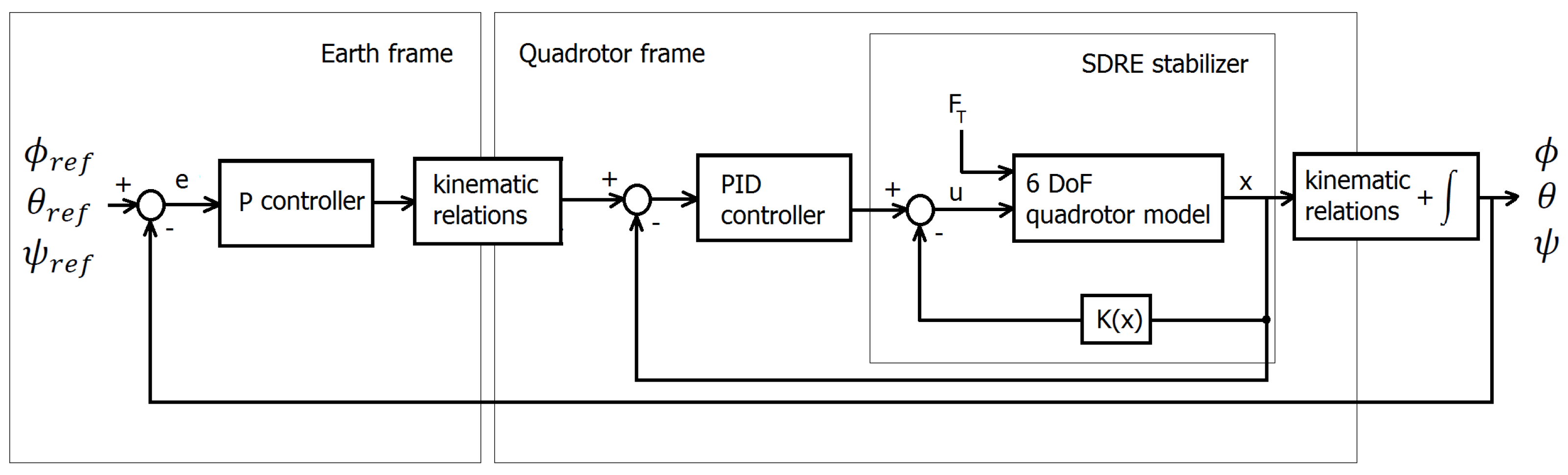
3.1. PID-SDRE Attitude Controller

The quadrotor is an unstable plant. Therefore, a UAV control system should contain a stabilization subsystem in design to make attitude control fast in response and free from overshoots. Then, from the point of view of practical implementation and drone usefulness, both the angular and linear speeds should stabilize. This is a reason why two blocks of controllers are proposed: one to control the orientation in space by the angular position and the other to stabilize the angular quadrotor speeds. These requirements can be achieved by using a PID attitude controller coupled to PID stabilizers. However, the use of PID-type controllers has affected efforts to tune and achieve optimal performance for the control system. Thus, a better idea is to use the PID-SDRE coupled solution or full integrated SDRE controller, which does not need to be optimized because it is optimal for control purposes.
Taking into account the above, this paper deals with the hybrid PID-SDRE controller dedicated to attitude control and finite-time stabilization. The control system schema is presented in Figure 2.
As shown, the controller consists of three control units. The attitude control system is implemented in outer closed-loop systems using the P controller, but the speed stabilization problem is performed by the inner closed-loop subunit with the PID controller and the feedback compensator employing the finite-time SDRE control technique. The stabilization problem can also be realized by the following:
  • PID controller without SDRE stabilizer;
  • SDRE feedback compensator neglecting PID stabilizer.
This means that the PID speed controller or SDRE speed compensator is redundant and the system can work as a two-unit and two-closed-loop control system. In this case, a thrust force F T is set as constant and allows one to obtain the desired altitude. The other variables contained in Figure 2 denote: x = v ω T = u v w p q r T —state vector of the 6 DoF model, u = M x M y M z T —attitude control vector and error vector of the attitude angles e = ϕ r e f ϕ θ r e f θ ψ r e f ψ T .

3.2. P-PID Attitude Controller

The control system presented in Figure 2 includes two PID-based controllers: situated in the main loop P controller for attitude control and located in the inner loop PID controller for angular speed control (stabilization). The main P controller operates in the Earth frame and performs the UAV space orientation task, controlling the attitude angles: roll ϕ , pitch θ , and yaw ψ to the reference values. The inner-loop PID controller is used to stabilize the attitude speeds to zero. The PID-based control system works when fine and optimal tuning of P and PID controllers is achieved; however, sometimes it is problematic and not easy.
Considering the kinematic relations from Earth to the quadrotor frame, the control law for the main P controller is as follows
u P = p p q p r p = e ϕ e ψ s i n θ k p ϕ e θ c o s ϕ e ψ s i n ϕ c o s θ k p θ e ψ c o s ϕ c o s θ e θ s i n ϕ k p ψ ,
where
e = e ϕ e θ e ψ = ϕ r e f ϕ θ t h e t a ϕ ψ r e f ψ
is the error signal e , which is a vector of three elements fed to the P controller. The PID controller used to stabilize the quadrotor space consists of three independent controllers for the rolling speed p , the pitching speed q , and the yawing speed r . The output of a PID controller u PID = M x P I D M y P I D M z P I D T is calculated in the time domain from the feedback speed error as follows:
u PID = k P ω + k I ω d t + k D d ω d t .
The speed error signal is equal to ω , because the reference angular speed is equal to zero. Then, a three-element vector fed to the PID controller is computed that performs the proportional, derivative, and integral functions of this signal with respect to time. k P , k I , and k D are proportional, integral, and derivative gain matrices:
k P = d i a g k P p , k P q , k P r , k I = d i a g k I p , k I q , k I r , k D = d i a g k D p , k D q , k D r .
The integral matrix gain k I times the integral of the error vector plus the derivative matrix gain k D times the derivative of the error vector are calculated using its approximation and creating the digital form of the PID. This is a standard formulation of digital PID that uses the bilinear transformation of the continuous integral and derivative action [1].

3.3. Finite-Time SDRE Stabilizer

The state-dependent Riccati equation (SDRE) optimal control method is a promising and rapidly emerging tool for the control of non-linear systems. The technique with further improvement and a modified approach is widely described in recent literature [19,20,21,22,23]. Scientists can follow the state-dependent Riccati equation (SDRE) approach in the context of the non-linear control problem with a quadratic objective function [24,25,26,27]. The formulation based on a quadratic objective function is commonly used in practical solutions because the objective function defines energy, i.e., energy lost and delivered to the system, which is compatible with practical applications.
The finite-time control problem consists of finding an optimal control law that minimizes the following objective function defined for control time t f [28]
J ( u ) = 1 / 2 x T ( t f ) S ( x ( t F ) ) x ( t f ) + 1 / 2 0 t f x T Q ( x ) x + u T R ( x ) u d t
subject to non-linear dynamics for affine systems
x ˙ = F ( x ) + B ( x ) u .
Non-linear dynamics (18) can be written using the state-dependent coefficient (SDC) form [29]
x ˙ = A ( x ) x + B ( x ) u ,
where S ( x ) and Q ( x ) are symmetric, positive semi-definite weighting matrices for states, and R ( x ) is the symmetric, positive definite weighting matrix for control inputs. Equation (18) includes the vector F ( x ) , which is piecewise continuous in time and smooth with respect to its arguments, and that satisfies the Lipschitz condition.
Taking into account the SDC approximation (19), if the pair A ( x ) , B ( x ) is a stabilizable parameterization of the system, then to check the controllability of the affine system, this pair in the linear sense should be controllable. On the other hand, checking the controllability of that pair does not require state or control input information [19,21,27]. It can be simply checked by the matrix
M ( x ) = B ( x ) A ( x ) B ( x ) A n 1 B ( x )
often called the controllability matrix. Then, the system (18) or (19) is controllable if the controllability matrix (20) has full rank.
Employing Hamiltonian theory, the optimal control law is as follows
u = R ( x ) 1 B ( x ) T K ( x ) x ,
where K ( x ) is a state-dependent feedback compensator that can be obtained from the solution of a state-dependent differential Riccati equation (SDDRE)
K ˙ ( x ) + K ( x ) A ( x ) + A ( x ) T K ( x ) K ( x ) B ( x ) R ( x ) 1 B ( x ) T K ( x ) + Q ( x ) = 0 .
Equation (22) is in the form of a differential SDRE for affine systems and must be solved many times for each x throughout the control process with the final condition K ( x ( t f ) ) = S ( x ( t f ) ) . The solution of the equation exactly results in suboptimal control because it neglects the so-called ’SDRE necessary condition for optimality’, which tends to zero [19,23,27]. Equation (22) known as differential SDRE or shortly SDDRE (State-Dependent Differential Riccati Equation); it can be solved numerically employing different algorithms. In the literature, there are many efficient algorithms dedicated to finding a solution of the SDDRE. The most popular are: backward iteration, state transition matrix approach, Lyapunov-based method, Riccati root method, etc. [30].

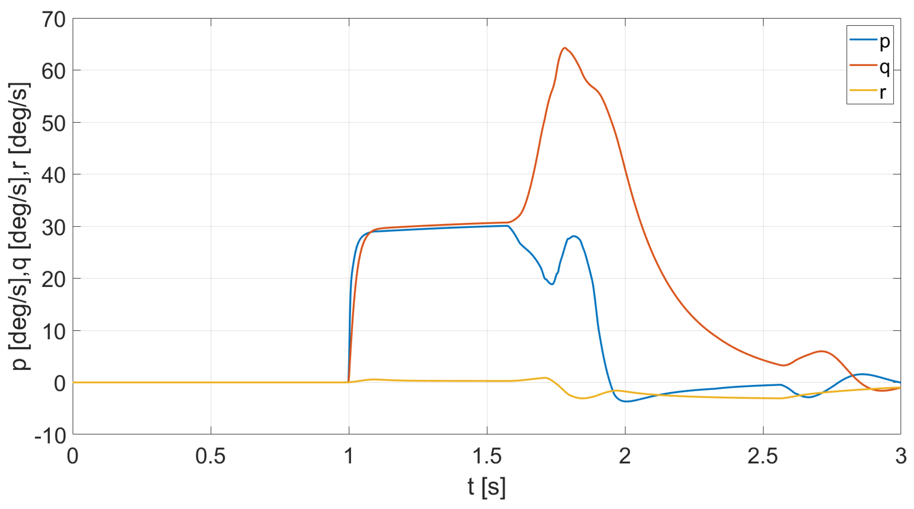
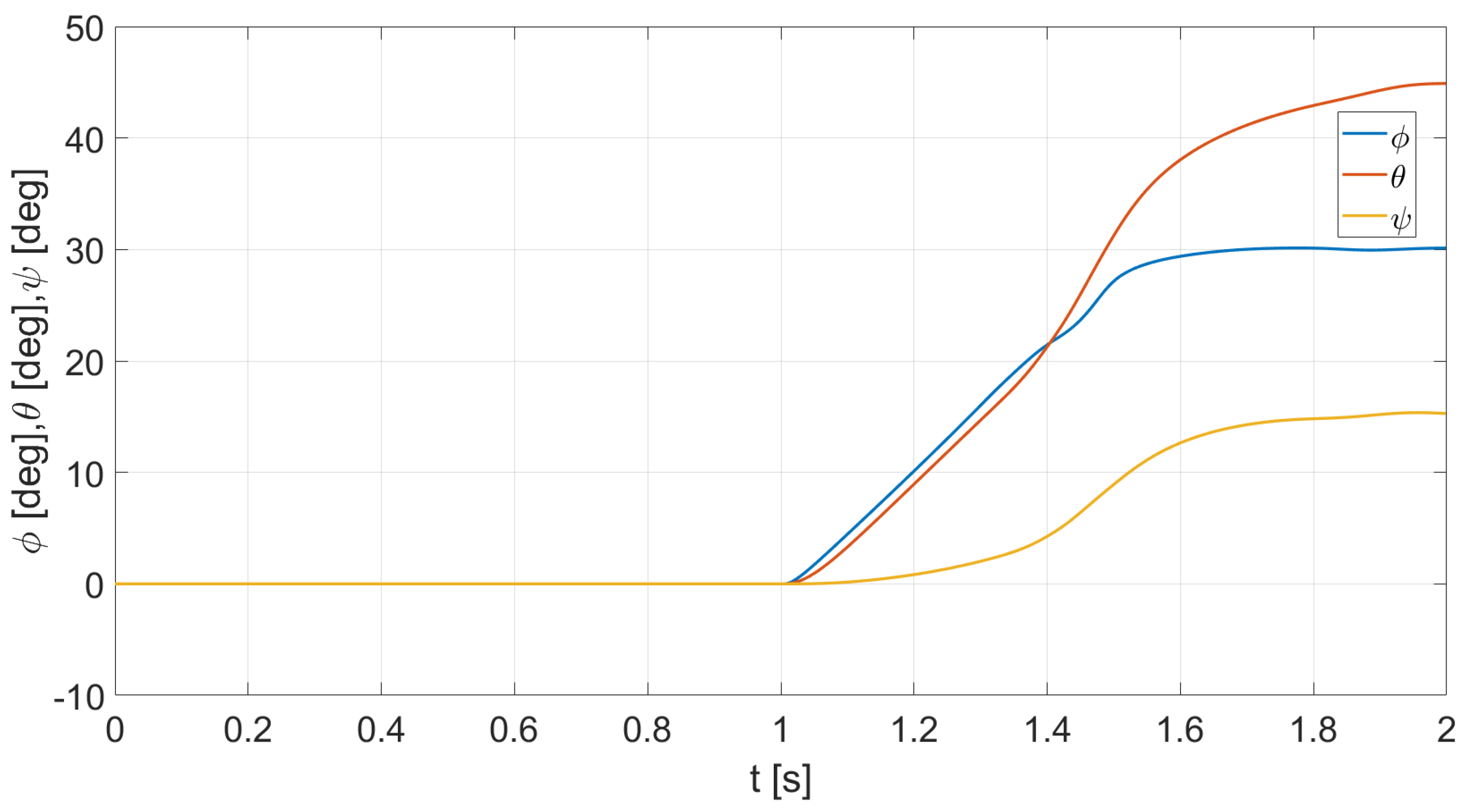
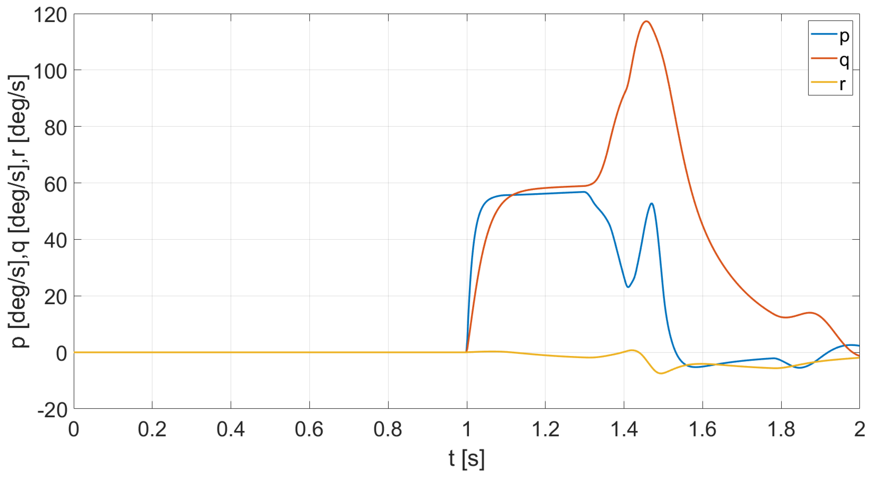
4. Experimental Results

4.1. UAV Used in Simulation Experiments

In the conducted experiments with the use of MATLAB/Simulink environment, a dynamical model of a military AtraxASF drone (shown in Figure 1) was used. AtraxASF is a quadrotor specially designed to perform precise test flights to inspect wild animals, especially in terms of detecting wild boars suffering from ASF (African swine fever). It was built as part of the research and development project financed by the National Center for Research and Development (Poland) and constructed by the Air Force Institute of Technology (ITWL, Warsaw, Poland). The UAV is equipped with a high-resolution thermal imaging sensor and has the following parameters:
  • Take-off mass: 13 kg,
  • Max. flight time: 40 min,
  • Flight range: 4.5 kg,
  • Optimal flight speed: 30 km/h,
  • Max. flight speed: 60 km/h.
This military UAV was chosen to be modeled, as the authors of this article have all the UAV data (some can be provided on request) and its hardware and software characteristics gathered and verified during laboratory, test stand, and flight tests with AtraxASF.

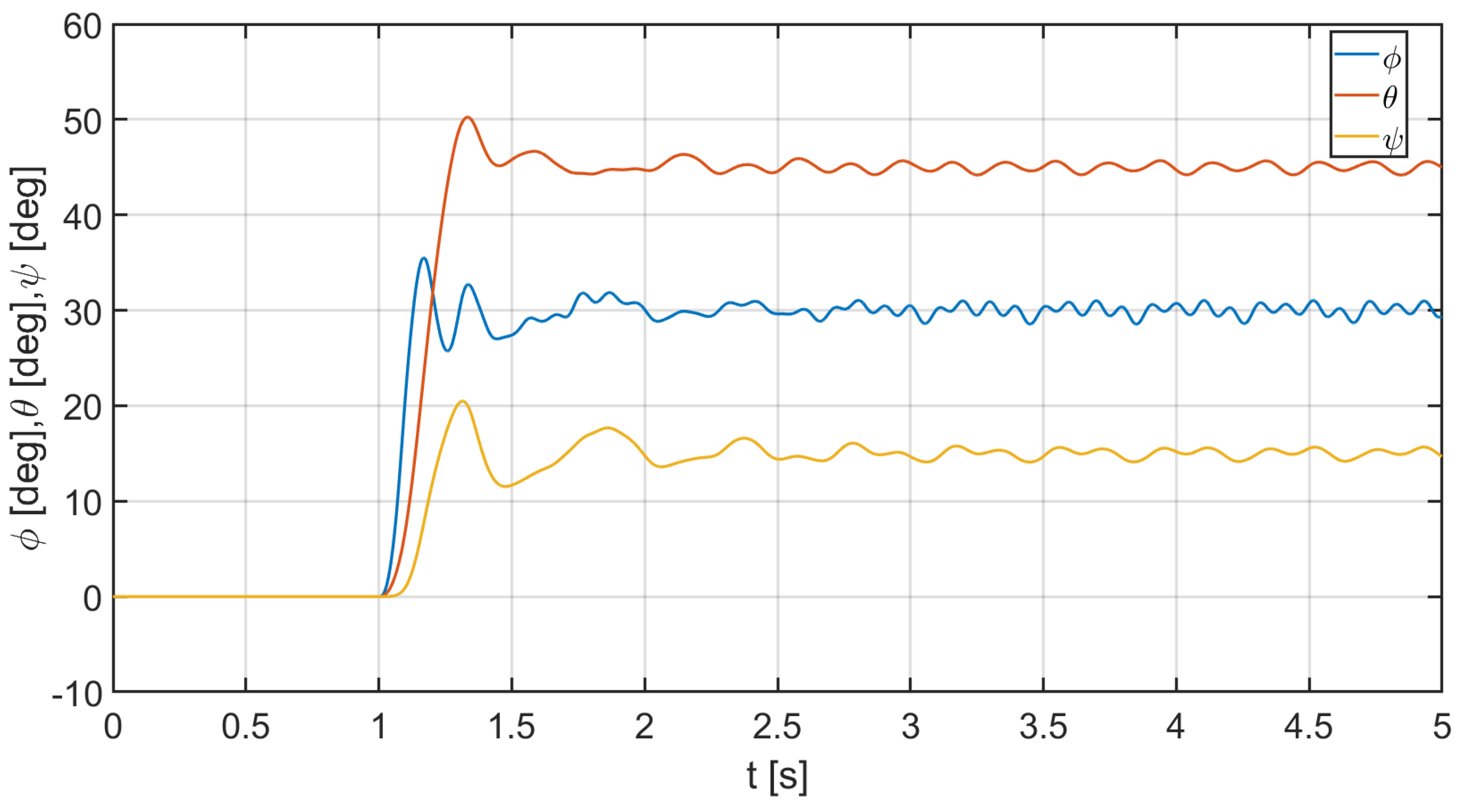
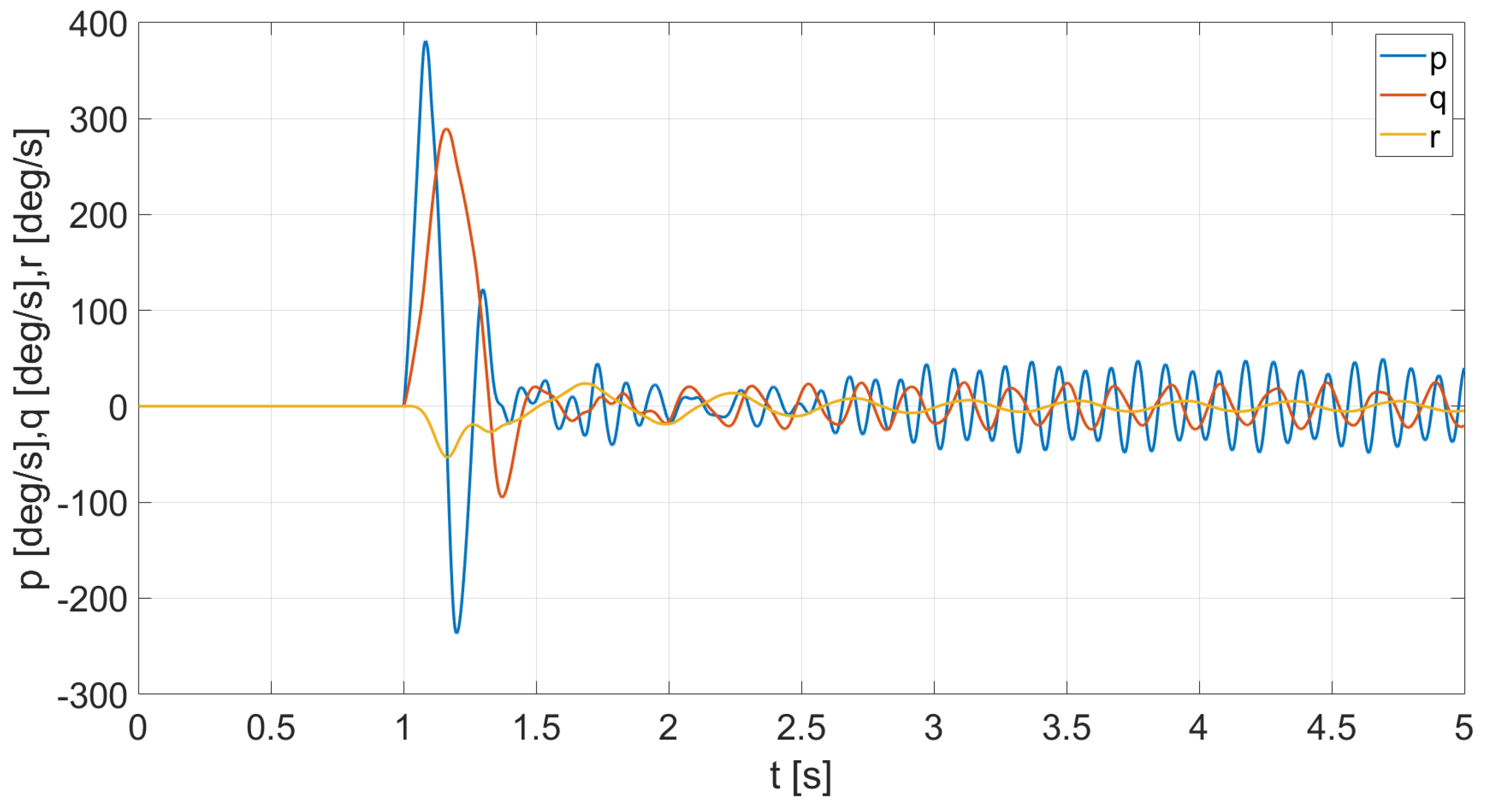
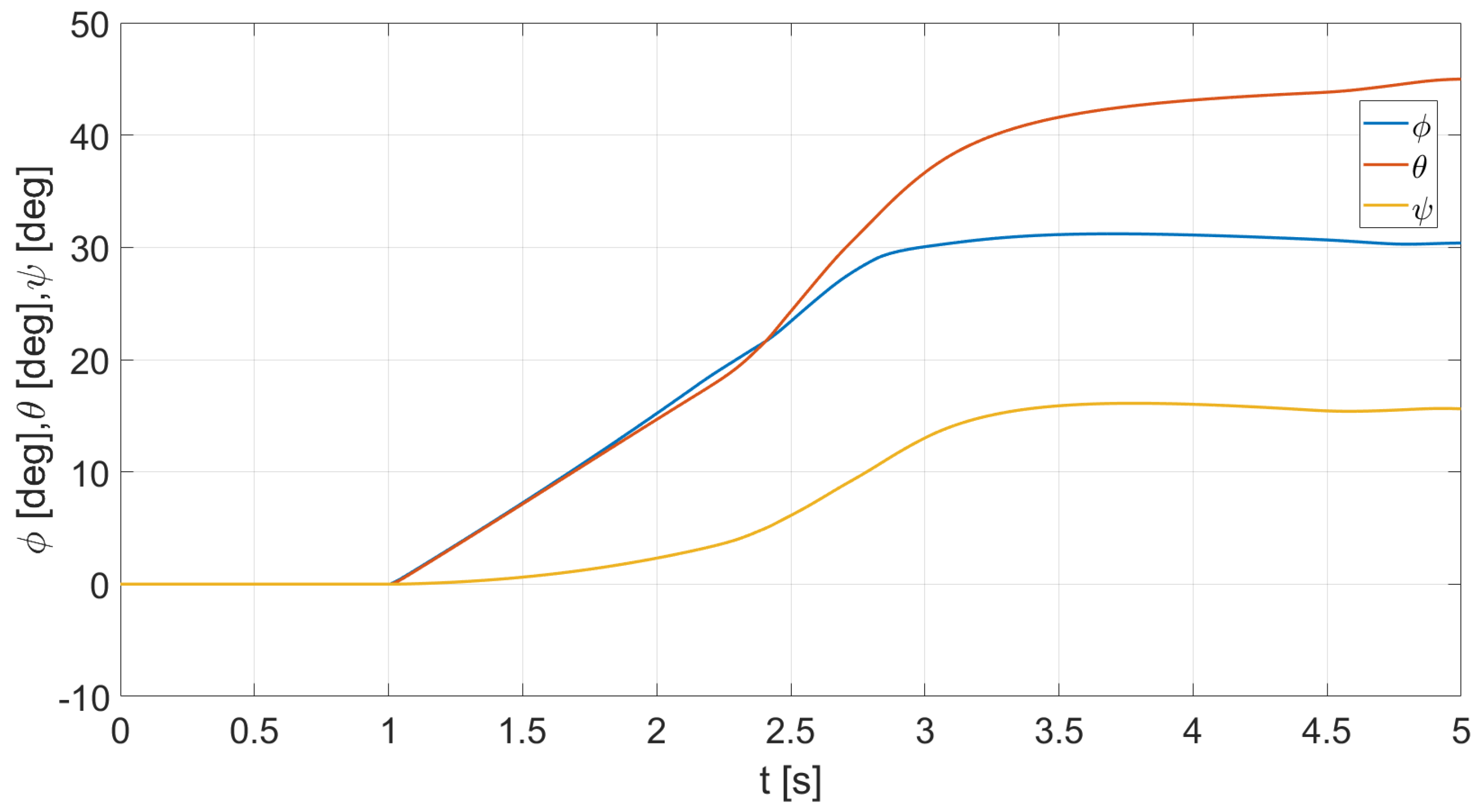
4.2. Simulation Experiments

The non-linear UAV model is applied to check the PID-SDRE control for attitude and stabilization when it tries to find the desired angular position during flight or take-off. Using the governing equations that describe the UAV aerodynamics in SDC form (19), the control problem consists of finding the ϕ , θ , and ψ moments with trust generated by UAV rotors. As defined in (6) and shown in Figure 2, the thrust acts positively along the positive body axis z. To perform the attitude control, to adjust its ψ angle, or to make it turn left or right, the vehicle applies more thrust to one set of motors generating ψ moment. ϕ and θ are adjusted by applying more thrust to one rotor and less to the other opposing rotor, generating ϕ and θ moments. In this simple way, rolling, pitching, or yawing moments are generated. According to the control schema proposed in Figure 2, the control applied to the UAV is a sum of the PID control and the SDRE stabilizator control, where the controller outputs are ϕ , θ , and ψ moments. Z-axis force related to altitude is assumed to be constant, and the forces on the x and y axes generated by the controller are neglected. Therefore, the output of an SDRE subcontroller u SDRE = M x S D R E M y S D R E M z S D R E T is calculated from (21). Using the described UAV model, the PID-SDRE control technique is applied to control the UAV attitude considering finite-time horizon SDRE feedback compensation for stabilization. To be exact, as shown in Figure 2, the attitude is controlled by the P controller (13), but the PID stabilization works, zeroing angular speeds (15). An additional SDRE feedback compensator additionally stabilizes the UAV angular position and makes it possible not only in finite time but also for rapid attitude changes. Briefly, the PID-SDRE method makes possible rapid response for user commands and moreover enables rapid stabilization of the path of flight when unexpected external forces try to change its position and orientation during flying action. Taking into account the above, the control problem consists of finding the state dynamics of the UAV and the PID-SDRE controls for the prescribed attitude for ϕ r e f = 30 deg, θ r e f = 45 deg, ψ r e f = 15 deg with and reference angular speed p r e f = 0 deg/s, q r e f = 0 deg/s, r r e f = 0 deg/s.
In association with (13), the gains of the P attitude controller are: k P ϕ = 10 , k P θ = 20 , k P ψ = 100 . PID stabilizer gains (15) are chosen as: k P = 0 , 3 I 3 × 3 , k I = 0 , 1 I 3 × 3 , k D = d i a g ( 0.01 , 0.01 , 0.0 ) and finally, the quadratic functional cost weighting matrices defined in (22) are as follows: S = 2 I 6 × 6 , Q = 0 , 5 I 6 × 6 and R = 0 , 1 I 6 × 6 .
The dynamics of the state of the UAV, in other words, the speed response, including its orientation to the desired angle position, is shown in Figure 3 and Figure 4. The UAV attitude control has been activated at time t = 1 s; then, the UAV angulary has been moved from the “zero” attitude to the reference angular position. First, simulations are performed for the UAV controlled by the P and PID stabilizer only, neglecting the SDRE stabilizer.
Looking at the above figures (Figure 3 and Figure 4), the angular position and speed responses are quick due to the large gains in the P-controller. However, the presented P-PID technique controls the attitude with overshoots and oscillations. Generally, the control works and is easy to implement; however, the system fails in precision operation in airspace. In this type of control, stabilization and improvement of accuracy seems to be necessary.
Next, simulations are performed for the complete PID-SDRE controller to show how the UAV can stabilize in a finite time t f in the context of angular speeds. To verify precision and rapidity and to compare the proposed technique considering the SDRE-based method with the commonly used PID technique, a numerical experiment is performed three final times: t f = 4 s, t f = 2 s, and t f = 1 s with the same reference attitude. The simulation results are presented in Figure 5, Figure 6, Figure 7, Figure 8, Figure 9 and Figure 10 with the impact of the successively reduced control time t f from 4 to 1 s.
When looking at and analyzing Figure 5 and Figure 6, the proposed PID-SDRE control shows that the quadrotor can be successfully controlled to referenced angles, zeroing angular speed, and reducing or eliminating overshoots. As expected, the referenced attitude is reached at the control time t f = 4 s. When considering the following Figure 7, Figure 8, Figure 9 and Figure 10, the same results are obtained for different control times t f = 2 s and t f = 1 s. Therefore, the insertion and use of the SDRE optimal stabilizer in the standard PID control system increases the complexity of the controller, making a hybrid PID-SDRE controller appropriate, because it allows for avoiding oscillations and allows the possibility of operating in airspace with high precision and adjustable control time t f . The results presented as an effect of performed numerical experiments prove the usefulness and correctness of the proposed technique; moreover, they allow us to verify its behavior.

5. Conclusions

The hybrid PID-SDRE finite-time control technique is formulated and solved for the UAV-quadrotor attitude control problem. The UAV non-linear 6 DoF state-dependent parametrized model is proposed. The P-PID fine-tuned control methodology with an optimal non-linear SDRE feedback speed stabilizer, performing attitude control and stabilization task, is analyzed. The effectiveness of the presented technique is demonstrated in a numerical example in which a UAV response is found using a finite-time SDRE-based technique. The presented results show that the proposed technique can be successively applied to UAV flight control systems when it must operate precisely in airspace. The next step of the analysis and research performed is preparation for application in a real UAV control system.

Author Contributions

Methodology, W.G. and S.S.; software, M.C.; validation, W.G. and S.S.; writing—original draft preparation, W.G. and M.C.; writing—review and editing, W.G., M.C. and S.S.; supervision, A.W. All authors have read and agreed to the published version of the manuscript.

Funding

This research was financially supported as a statutory work of the Poznan University of Technology (No. 0214/SBAD/0237).

Institutional Review Board Statement

Not applicable.

Informed Consent Statement

Not applicable.

Data Availability Statement

Not applicable.

Conflicts of Interest

The authors declare no conflict of interest.

Abbreviations

The following abbreviations are used in this manuscript:
BFBody Frame
EFEarth Frame
EKFExtended Kalman Filter
GPSGlobal Positioning System
INSInertial Navigation System
NEDNorth-East-Down
PIDProportional–Integral–Derivative Controller
QTW UAVQuad Tilt-Wing Unmanned Aerial Vehicle
SDCState-Dependent Coefficient
SDREState-Dependent Riccati Equation
UAVUnmanned Aerial Vehicle

References

  1. Kim, J.; Gadsden, S.A.; Wilkerson, S.A. A Comprehensive Survey of Control Strategies for Autonomous Quadrotors. Can. J. Electr. Comput. Eng. 2020, 43, 3–16. [Google Scholar] [CrossRef]
  2. Kornatowski, P.M.; Bhaskaran, A.; Heitz, G.M.; Mintchev, S.; Floreano, D. Last-Centimeter Personal Drone Delivery: Field Deployment and User Interaction. IEEE Robot. Autom. Lett. 2018, 43, 3813–3820. [Google Scholar] [CrossRef]
  3. Rao, J.; Li, B.; Zhang, Z.; Chen, D.; Giernacki, W. Position Control of Quadrotor UAV Based on Cascade Fuzzy Neural Network. Energies 2022, 15, 1763. [Google Scholar] [CrossRef]
  4. Lungu, M. Auto-landing of UAVs with variable centre of mass using the backstepping and dynamic inversion control. Aerosp. Sci. Technol. 2020, 103, 105912. [Google Scholar] [CrossRef]
  5. Orsag, M.; Korpela, C.; Oh, P. Modeling and Control of MM-UAV: Mobile Manipulating Unmanned Aerial Vehicle. J. Intell. Robot. Syst. Vol. 2013, 69, 227–240. [Google Scholar] [CrossRef]
  6. Huang, H.; Zhao, X.; Zhang, X. Intelligent Guidance and Control Methods for Missile Swarm. Comput. Intell. Neurosci. 2022, 2022, 8235148. [Google Scholar] [CrossRef]
  7. Voos, H. Nonlinear state-dependent Riccati equation control of a quadrotor UAV. In Proceedings of the 2006 IEEE Conference on Computer Aided Control System Design, 2006 IEEE International Conference on Control Applications, 2006 IEEE International Symposium on Intelligent Control, Munich, Germany, 4–6 October 2006; pp. 2547–2552. [Google Scholar] [CrossRef] [Green Version]
  8. Nemra, A.; Aouf, N. Robust INS/GPS Sensor Fusion for UAV Localization Using SDRE Nonlinear Filtering. IEEE Sens. J. 2010, 10, 789–798. [Google Scholar] [CrossRef] [Green Version]
  9. Khamis, A. Nonlinear Finite-Horizon Regulation and Tracking for Systems with Incomplete State Information Using Differential State Dependent Riccati Equation. Int. J. Aerosp. Eng. 2014, 78628, 178628. [Google Scholar] [CrossRef] [Green Version]
  10. Takayama, T.; Uchiyama, K.; Masuda, K. Controller Design Using SDRE Method for Tilt-Wing UAV. In Proceedings of the 2020 11th International Conference on Mechanical and Aerospace Engineering (ICMAE), Athens, Greece, 14–17 July 2020; pp. 102–106. [Google Scholar] [CrossRef]
  11. Hua, Z. Suboptimal Integral Sliding Mode Trajectory Tracking Control of a UAV Based on SDRE Method. In Advances in Guidance, Navigation and Control, Proceedings of the 2020 International Conference on Guidance, Navigation and Control, ICGNC 2020, Tianjin, China, 23–25 October 2020; Part of the Lecture Notes in Electrical Engineering Book Series (LNEE); Springer: Singapore, 2021; Volume 644, pp. 67–77. [Google Scholar] [CrossRef]
  12. Guerrero-Sanchez, M.E.; Lozano, R.; Castillo, P.; Hernandez-Gonzalez, O.; Garcia-Beltran, C.D.; Valencia-Palomo, G. Nonlinear control strategies for a UAV carrying a load with swing attenuation. Appl. Math. Model. 2021, 91, 709–722. [Google Scholar] [CrossRef]
  13. Nekoo, S.R.; Acosta, J.A.; Ollero, A. Quaternion-based state-dependent differential Riccati equation for quadrotor drones: Regulation control problem in aerobatic flight. Robotica 2022, 40, 1–16. [Google Scholar] [CrossRef]
  14. Nekoo, S.R.; Acosta, J.A.; Ollero, A. Geometric control using the state-dependent Riccati equation: Application to aerial-acrobatic maneuvers. Int. J. Control. 2021, 1–16. [Google Scholar] [CrossRef]
  15. Nekoo, S.R.; Acosta, J.A.; Ollero, A. Collision Avoidance of SDRE Controller using Artificial Potential Field Method: Application to Aerial Robotics. In Proceedings of the 2020 International Conference on Unmanned Aircraft Systems (ICUAS), Athens, Greece, 1–4 September 2020. [Google Scholar] [CrossRef]
  16. Monti, C. Model-Free Control of an Unmanned Aircraft Quadcopter Type System; Rochester Institute of Technology: Rochester, NY, USA, 2020. [Google Scholar]
  17. Bold, S.; Sosorbaram, B.; Chuluunjav, S. Mathematical Model Based PID Control of the Raspi Drone. Lect. Notes Electr. Eng. 2021, 712, 29–39. [Google Scholar] [CrossRef]
  18. Karahan, M.; Kasnakoglu, C. Modeling and Simulation of Quadrotor UAV Using PID Controller. In Proceedings of the 2019 11th International Conference on Electronics, Computers and Artificial Intelligence (ECAI), Pitesti, Romania, 27–29 June 2019. [Google Scholar]
  19. Banks, H.T.; Lewis, B.M.; Tran, H.T. Nonlinear feedback controllers and compensators: A state-dependent Riccati equation approach. Comput. Optim. Appl. 2018, 37, 177–218. [Google Scholar] [CrossRef] [Green Version]
  20. Çimen, T.; Banks, S.P. Global optimal feedback control for general nonlinear systems with non-quadratic performance criteria. Syst. Control Lett. 2004, 53, 327–346. [Google Scholar] [CrossRef]
  21. Çimen, T. Systematic and effective design of nonlinear feedback controllers via the state-dependent Riccati equation (SDRE) method. Annu. Rev. Control. 2010, 34, 32–51. [Google Scholar] [CrossRef]
  22. Cloutier, J.R.; D’Souza, C.N.; Mracek, C.P. Nonlinear regulation and nonlinear H control via the state-dependent Riccati equation technique: Part 1, Theory; Part 2, Examples. In Proceedings of the First International Conference on Nonlinear Problems in Aviation and Aerospace, Daytona Beach, FL, USA, 9–11 May 1996; pp. 117–141. [Google Scholar]
  23. Shamma, J.S.; Cloutier, J.R. Existence of SDRE stabilizing feedback. IEEE Trans. Autom. Control. 2003, 48, 513–517. [Google Scholar] [CrossRef]
  24. Erdem, E.B.; Alleyne, A.G. Design of a class of nonlinear controllers via state dependent Riccati equations. IEEE Trans. Control. Syst. Technol. 2004, 12, 133–137. [Google Scholar] [CrossRef]
  25. Hammett, K.D.; Hall, C.D.; Ridgely, D.B. Controllability issues in nonlinear state-dependent Riccati equation control. J. Guid. Control. Dyn. 1998, 21, 767–773. [Google Scholar] [CrossRef]
  26. Heydari, A.; Balakrishnan, S.N. Closed-form solution to finite-horizon suboptimal control of nonlinear systems. Int. J. Robust Nonlinear Control 2015, 25, 2687–2704. [Google Scholar] [CrossRef]
  27. Mracek, C.; Cloutier, J. Control designs for the nonlinear benchmark problem via the state-dependent Riccati equation method. Int. J. Robust Nonlinear Control. 1998, 8, 401–433. [Google Scholar] [CrossRef]
  28. Wernli, A.; Cook, G. Suboptimal control for the nonlinear quadratic regulator problem. Automatica 1975, 11, 75–84. [Google Scholar] [CrossRef]
  29. Liang, Y.; Lin, L. Analysis of SDC matrices for successfully implementing the SDRE scheme. Automatica 2013, 49, 3120–3124. [Google Scholar] [CrossRef]
  30. Korayem, M.; Nekoo, S. Finite-time state-dependent Riccati equation for time-varying nonaffine systems: Rigid and flexible joint manipulator control. ISA Trans. 2015, 54, 125–144. [Google Scholar] [CrossRef] [PubMed]
Figure 1. AtraxASF UAV used for drone modeling and simulation experiments.
Energies 15 04312 g001
Figure 2. PID-SDRE control schema of the 6 DoF quadcopter model.
Energies 15 04312 g002
Figure 3. UAV angular response—PID control mode.
Energies 15 04312 g003
Figure 4. UAV angular speed response—PID control mode.
Energies 15 04312 g004
Figure 5. Angular response of UAV—PID-SDRE control mode, t f = 4 s.
Energies 15 04312 g005
Figure 6. UAV angular speed response—PID-SDRE control mode, t f = 4 s.
Energies 15 04312 g006
Figure 7. Angular response of UAV—PID-SDRE control mode, t f = 2 s.
Energies 15 04312 g007
Figure 8. UAV angular speed response—PID-SDRE control mode, t f = 2 s.
Energies 15 04312 g008
Figure 9. Angular response of the UAV—PID-SDRE control mode, t f = 1 s.
Energies 15 04312 g009
Figure 10. UAV angular speed response—PID-SDRE control mode, t f = 1 s.
Energies 15 04312 g010
Publisher’s Note: MDPI stays neutral with regard to jurisdictional claims in published maps and institutional affiliations.

