Article

Smart Predictive Maintenance Device for Critical In-Service Motors

by
Emil Cazacu
*,
Lucian-Gabriel Petrescu
and
Valentin Ioniță
Department of Electrical Engineering, Faculty of Electrical Engineering, Polytechnic University of Bucharest, 313 Splaiul Independentei, 060042 Bucharest, Romania
*
Author to whom correspondence should be addressed.
Energies 2022, 15(12), 4283; https://doi.org/10.3390/en15124283
Submission received: 16 May 2022 / Revised: 4 June 2022 / Accepted: 8 June 2022 / Published: 10 June 2022
(This article belongs to the Section F: Electrical Engineering)

Abstract

:
The paper proposed an innovative predictive maintenance system, designated to monitor and diagnose critical electrical equipment (generally large power electric motors) within industrial electrical installations. A smart and minimally invasive system is designed and developed. Its scope is to evaluate continuously the essential operating parameters (electrical, thermal, and mechanical) of the investigated equipment. It manages to report the deviations of inspected machine operating parameters values from the rated ones. The system also suggests the potential cause of these abnormal variations along with possible means (if the defect is identified in a database, constantly updated with each appearance of a malfunction). The developed maintenance device generates an operating report of the analyzed equipment, in which the values of power quality and energy indicators are computed and interpreted. Additionally, real-time remote transmission of analyzed data is facilitated, making them accessible from any location. The proposed maintenance system is a low-cost device that is easy to install and use in comparison with similar existing devices and equipment. The designed maintenance system was tested on dedicated to low-voltage equipment up to 100 kW.

Graphical Abstract

1. Introduction

The requirement nowadays for constant performance in large production facilities of any kind is expressed in terms of high-quality products manufactured at low costs. These demands determined the company’s management to develop specific organizational and technical measurements. One of these actions, of paramount importance, is to reduce the accidental shutdowns of the critical equipment, directly involved in the production process. Nowadays, the most common critical electrical equipment encountered in industrial installations are electromechanical converters, i.e., usually large power electric motors from the various electric drive systems. Consequentially, the analysis of maintenance procedures will focus on these distinctive electric loads. The main principles of this action are indicated in [1,2], while in [3,4,5], its limits and performances are revealed.
The technological development of the last decades [6,7] has made the share of corrective and reactive maintenance (intervention after occurrence, respectively at the manifestation of a fault) or even preventive (performed periodically) within the maintenance service to be significantly reduced in the favor of predictive. The latter continuously compares the most important operating parameters trend values for electrical, thermal, and mechanical quantities of investigated equipment with their accepted limits [8,9,10]. This enables the detection, analysis, and even correction of various malfunctions before they manifest (avoiding the appearance of a defect) [7,8,10]. These significant investigations capabilities were mainly feasible due to the increased computing power [7,9].
Currently, in most companies with various fields of activity, the maintenance of critical electrical equipment is preventively and not predictively performed. This is carried out by simple monitoring the power quality parameters, assessing thermal indicators (by temperature measurement) and mechanical stress (by vibration analysis) [6,7,8]. However, this kind of implementing the maintenance service requires considerable investments in high-precision apparatus and equipment (power quality analyzers, industrial oscilloscopes, vibration analyzers, and thermal imaging cameras) that provide numerous and different operating parameters. These need to be furthermore processed, analyzed (using computerized systems), and finally correctly interpreted by a suitably qualified operator.
Unfortunately, this frequently used maintenance services cannot provide a real-time and on-site analysis together with a diagnosis of the investigated critical equipment operation. The cause of a fault could be identified starting from a journalized correlation of all variations of operation parameters. Consequently, a non-comprehensive approach can lead to inefficient actions in terms of maintenance and diagnosis of the machine unproper functionality. Thus, the most suitable investigation could only be achieved from the integrative interpretation analysis adequately correlated with visualization of all monitored parameters [10,11]. Some other maintenance principles are based on the insulation aging detection [12] or bearing fault signaling [13]. Even laboratory maintenance tests were developed [14] or such systems dedicated to photovoltaic applications [15].
To respond to these demands, this paper suggests a simple, intuitive, and low-cost predictive maintenance system that continuously evaluates the essential operating parameters (electrical, thermal, and mechanical) of the investigated equipment and instantly notify their abnormal variation. Supplementary, this minimally invasive device manages to indicate the potential cause of the malfunctioning operation together with a possible corrective solution. That is achievable by creating a database of equipment faulty manifestations with their corresponding remedial actions. These predictive measures mainly base of the electrical motor voltage and current waveform signatures analysis [8,9,16,17] by also considering the power quality issues [18,19] and the machine surface thermal and mechanical measurements [18,19,20,21]. The faults database is permanently updated during the equipment exploitations. The developed predictive maintenance system also continuously generates an operation report of the analyzed equipment that indicates and interprets the values of the measured power quality parameters together with the equipment surface temperature variation and its vibration level. All these motor operating data are recorded by the maintenance device in a journalized manner. Additionally, a real-time, remote transmission of the measurement and processed data is facilitated too. The here-developed and investigated predictive maintenance system is very flexible and easy to implement, and only uses low-costs common electronic components and sensors. This makes it a very reliable and affordable solution to rather expensive and complex solutions offered by other similar commercial solutions.
The main drawbacks of the existing similar predictive maintenance devices are their complexity, high costs, and sometimes lacking flexibility, requiring specific connectivity’s schematics. Thus, the proposed maintenance system addresses this gap and due to its simplicity cope with the main field maintenance demands. Additionally, the novel device is to be applied to a large variety of equipment (not necessarily rotational) encountered in modern low-voltage installations.
The paper is organized in five sections. In the second section, the main causes and consequences of the motor faults are quantitatively presented, underlining their manifestations and identification procedures. The third section of the paper details the predictive maintenance device design and implementation, also exposing its main features. Section four is dedicated to discussions on the developed device performances and its limitations and describes its interconnection capabilities. The conclusions section sums up the device’s main novelty characteristics and suggests ways to improve its computation accuracy and extension of its addressability.

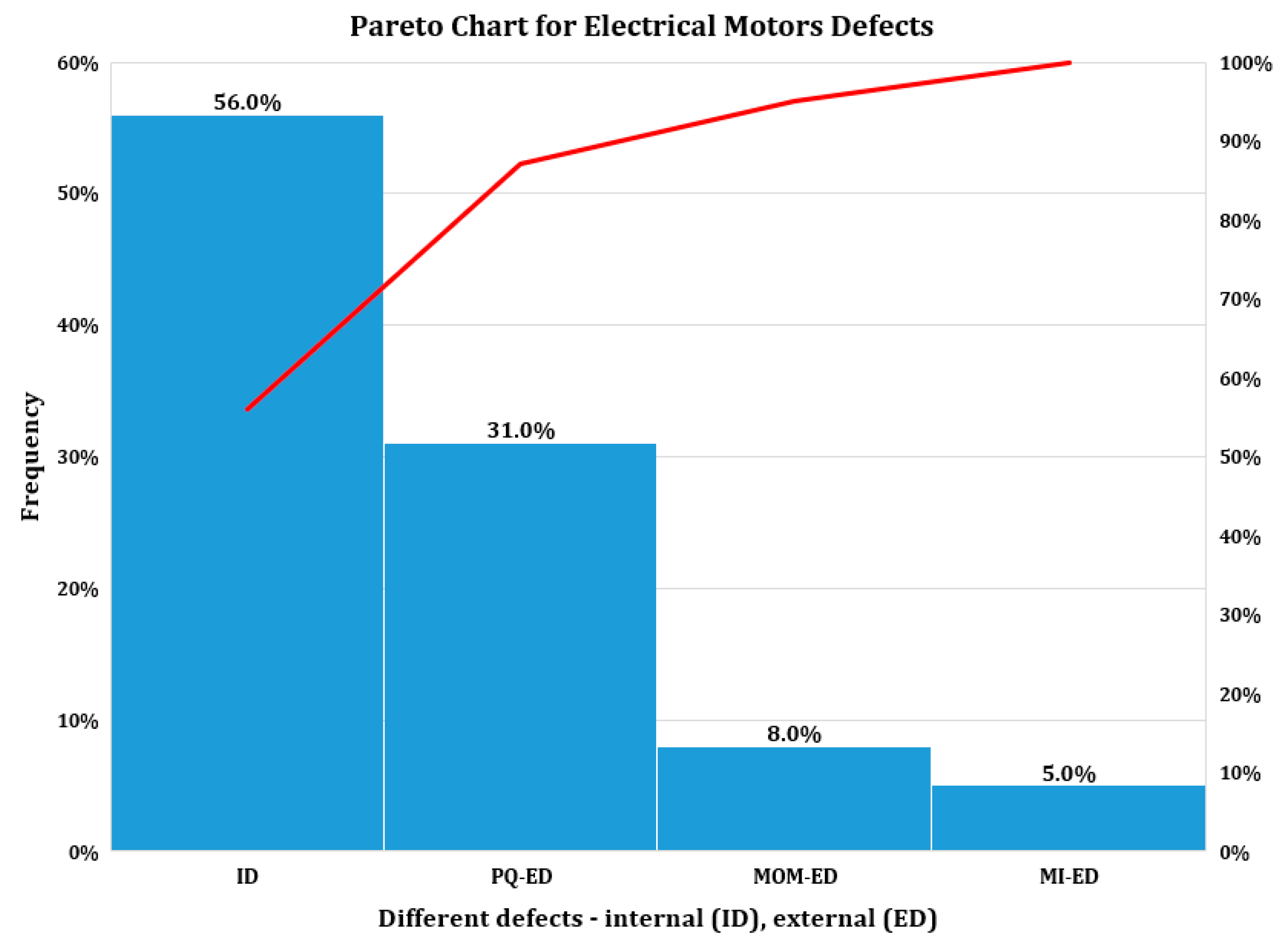
2. Motor Faults Causes and Consequences

In an electrical installation that includes drive systems, two major classes of faults that can affect electric motors, or the entire drive system, were discriminated [22,23,24]:
  • Internal defects (ID), which are mostly caused by short circuits between a phase and the metal casing, short circuits between phases or windings, overheating of the windings, breakage of a bar (for short-circuit rotor type motors), or problems related to tribology.
  • External defects, which have as causes various factors exogenous to the motor, such as:
    Power quality issues of the motor supply energy source (PQ-ED): harmonics, imbalances, voltages swells, sags or interruptions, overvoltage, etc.
    Motor misoperation mode (MOM-ED): various overloads, dysfunctional transient states (improper starts and stops), and loads with large rotational inertia.
    Motor mechanical installations issue (MI-ED): improper installation in the electric drives system: misalignment between motor and load, mechanical imbalances, overload of the shaft, etc.
This classification is rather feeble, since during motor exploitation, it becomes rather difficult to discriminate between internal and external faults [25,26,27,28]. In order to highlight the percentage occupied by each of the above-mentioned defects, a Pareto chart is shown in Figure 1.

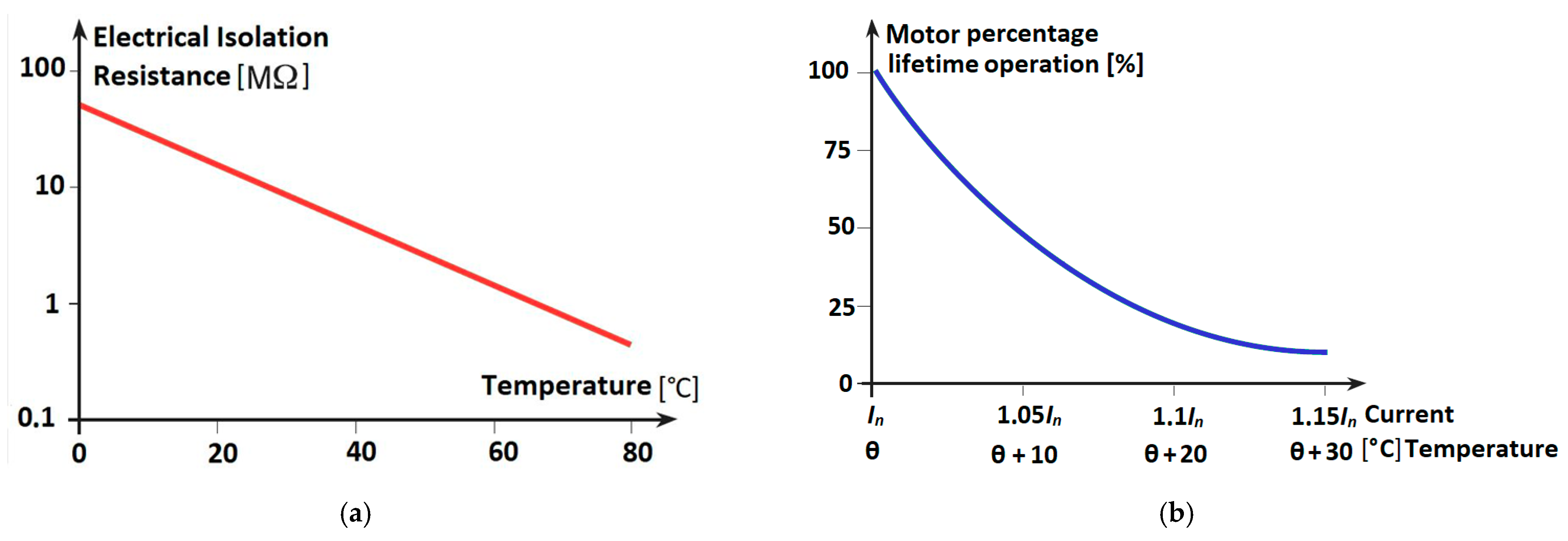
2.1. Motor Internal Faults

Internal faults are most often manifested by a motor as insulation defects. These faults can occur in both stator and rotor windings (for coiled rotor type motors). The degradation of the insulation can cause a permanent short-circuit between different motor active parts. The causes of these defects can be found in electrical (surface discharges, overvoltage), thermal (overheating), or even mechanical phenomena (vibrations, electrodynamic stresses in conductors, etc.) [21,22,23,24,25]. The most encountered causes of insulation crashes (in windings) are due to their overheating when the motor is overloaded. These are immediately signaled by a significant increase of the motor current effective values.
Figure 2a presents the variation of the motor insulation resistance as a function of temperature. Similarly, Figure 2b illustrates motor lifetime operation under the overload condition. These variations are usually indicated by most electric motor manufacturers. As Figure 2b indicates, an increase of only 5% in effective current, which leads to a 10 °C increase of winding temperature, halves the motor life [23,24,25]. Thus, the overload protection plays a key role in preventing overheating and reducing the risk of internal motor defects [26,27,28,29].

2.2. Motor External Faults

The external defects of the motors are mainly caused by power quality problem of the supply sources [29,30,31,32,33,34,35]. Consequently, our investigation is focused on these issues, especially on the harmonics and unbalanced conditions that are frequently found in low-voltage installations [35,36,37,38,39,40].

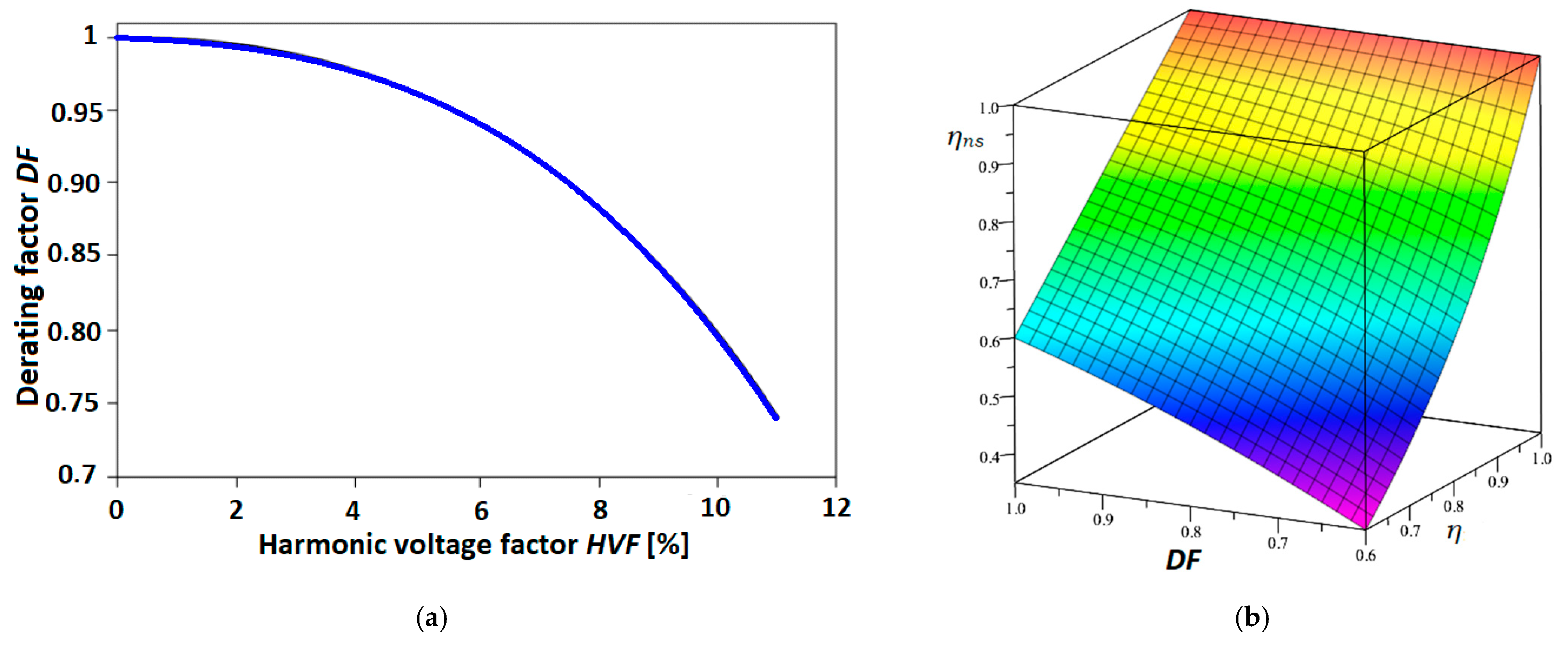
2.2.1. Supply Voltage Waveform Distortion

If the distribution system that energizes the motor has a low short-circuit power (a high internal impedance) and at the same time supplies strongly non-linear consumers, the voltage waveforms could exhibit an important distortion level. The main negative effects on the asynchronous motors powered by such distorted voltages are [35,36,37,38,39,40]:
  • Increased winding and magnetic core temperature, caused by additional losses in the conductive and magnetic materials (higher copper and iron losses).
  • Variations of the motor torque values, which leads to a reduction in its efficiency.
  • The appearance of oscillations of the motor torque at the shaft, which generates additional mechanical stresses on the electric drive system.
  • Interactions between the magnetic flux determined by the fundamental harmonic and those generated by the higher-order harmonics.
In order to preserve the characteristics of the motor supplied with non-sinusoidal voltages, the IEC TS 60034-25 standard [41] requires the denomination of its rated power—see Figure 3a. The associated derating factor DF is determined according to a specific power quality parameter harmonic voltage factor HVF:
H V F = k = 5 n 1 k ( U k U 1 ) 2 ,
where U1 represents the effective value of the voltage fundamental harmonic and Uk represents the effective values of the even harmonics of the voltage that are not divisible by 3.
A derating factor between 5 ÷ 10% can be assumed in very unfavorable cases (heavy harmonic polluted grid). If the voltage waveform is measured and analyzed (the HVF parameter is determined). The operating efficiency of the motor ηns can be expressed as a function of its rated efficiency η (under pure sinusoidal state) and the derating factor DF—as also shown in Figure 3b [32,33,34,35]:
η n s = η D F 2 1 + η ( D F 2 1 ) .
Variable speed drives, where induction motors are powered by static power converters (frequency converters), could also generate a highly distorted voltage. Under these conditions, it is necessary to analyze the practical possibilities of harmonic voltage mitigation or to reduce harmonic the network content. These actions decrease the motor overstresses and they can be performed in different ways: using controlled PWM converters (which preserve the voltage sinusoidal waveform), installing voltage harmonic filters, or powering the motor from a separate power source.

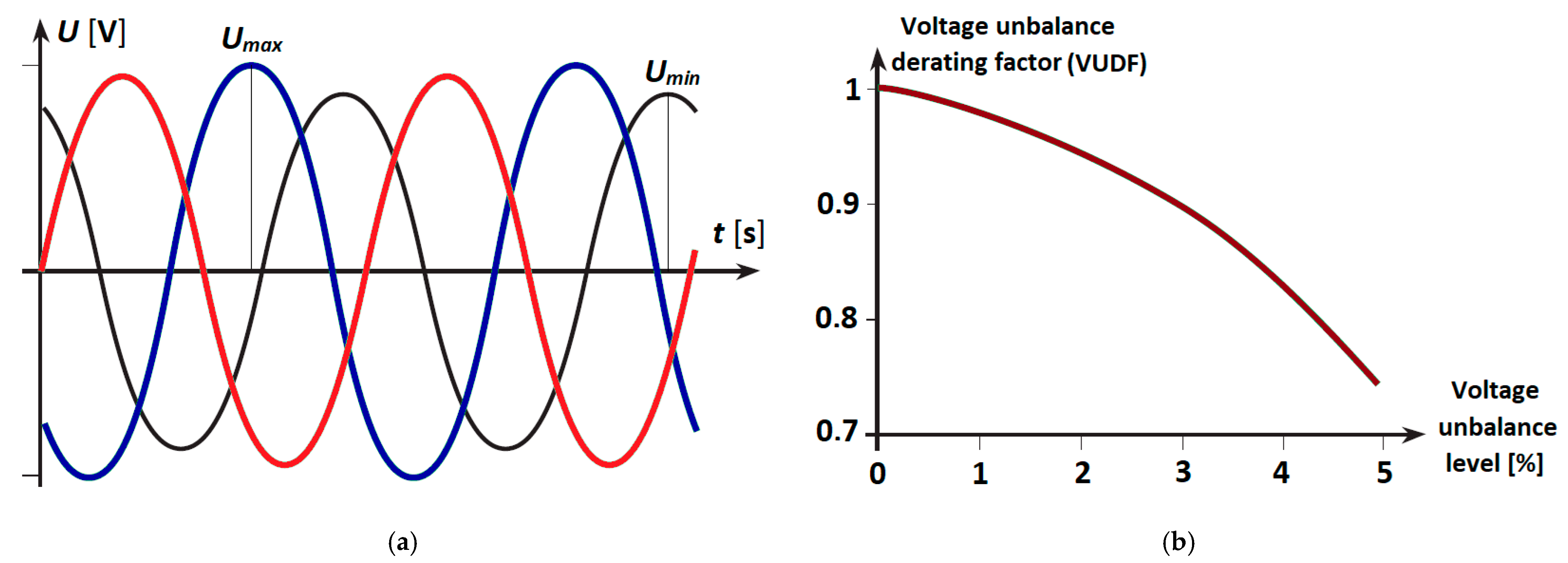
2.2.2. Supply Voltage Unbalance

The most important effect of the supply voltages unbalances on motors is overheating due to additional generated windings losses [34,35]. Additionally, they engender pulsating torques of high frequency that manifests by vibrations of the rotor [36,37,38,39,40]. At the same time, a significant reduction in engine efficiency is experienced, and ultimately, the motor lifespan is substantially reduced. Two different standards are nowadays used to quantitatively describe the level of unbalance for three-phase quantities (voltages and/or currents): the European standard [42] and the North American standard [43]. The North American standard is more adequate for field measurements, since it does not require sinusoidal quantities but only considers the asymmetry of their amplitude values by the factor kn:
k n = Δ U m a x U m e d 100 % = U max ( 1 , 2 , 3 ) U m e d U m e d 100 % , U m e d = U A + U B + U C 3 , U max ( 1 , 2 , 3 ) = max ( U A , U B , U C ) ,
where UA, UB, and UC represent the amplitudes of the three phase voltages of the investigated system.
It is important to mention that some power quality analyzers indicate an unbalance factor of the line voltages k s f , defined according to the maximum values voltages between phases UAB, UBC, and UCA [36,37,38,39,40]:
k s f = 1 3 6 β 1 + 3 6 β ,   β = U A B 4 + U B C 4 + U C A 4 ( U A B 2 + U B C 2 + U C A 2 ) 2 .
The standard IEC 60034-26 [41] provides a rule for derating motor power according to voltage unbalance—see Figure 4b. It may be used when this phenomenon is known or foreseeable into the network where the motor is supplied.
One can notice from Figure 4b that the lifespan of asynchronous motors decreases by 25%, to a voltage asymmetry of only 4% [36,37,38,39,40,41]. The voltage unbalance derating factor (VUDF) allows either to oversize the motor to withstand the effects of voltage imbalance or to reduce its available power. It is important to underline that the unbalance of three-phase voltages can also be determined by phase shifts other than 2π/3 between consecutive phase voltages. This usually has the effect of disrupting the operation of motor static power converters.

2.2.3. Voltage Swells, Sags, and Interruptions

Voltage swells can be temporary or permanent and could have various origins: atmospheric (lightning strike), electrostatic discharges, operation of a switching device connected to the same network as the motor, and many others [4,19]. They often overlap with the mains voltage and can occur both between the active conductors and the motor housing, as well as between the different motor constructive parts [26,27]. Most often, their effect breaks the windings insulation and finally destroys the motor [30,31,32].
The impact of voltage sags on induction motors is also significant. Thus, the decrease of the voltage value under the rated one has the following consequences: increase the absorbed current (overload), which could also determine an insulation defect, decrease the torques (nominal, maximum, and starting), due to their square dependence of voltage values (which can even lead to the inability of the motor to start under the rated load), and decrease the motor speed. Additionally, after an interruption, when the voltage returns to the rated value, the motor requires a re-accelerating current that has a value close to the starting one (inrush) current, causing significant thermal and electrodynamic stresses into the drive system. In addition, voltage converters and frequency converters are also severely affected by these voltage variations (swells and sags) [28,30].

2.2.4. Motor Misoperation Modes and Motor Mechanical Installations Issues

Due to its intrinsic characteristics, each motor can only withstand a limited number of starts, generally specified by the manufacturer (indicated as number of starts per hour). In addition, each motor has a maximum starting time, depending on its rated inrush (starting) current. One of the external faults with a high incidence is caused by motor starting process. This mostly happens due to an improper starting management, especially for large power motors.
Motor overload is also a common cause of external faults. This is usually caused by an increase in torque or a decrease in mains voltage (by at least 10% of rated one) [22,23,27]. This manifests by increasing the current absorbed by the motor that generates extra heat within its windings. Additionally, blocking a motor shaft due to a mechanical cause determine an overcurrent with values similar to the inrush currents but with a much more generated heat. That is explained because the losses in the rotor are maintained at the maximum value during the lock while the natural ventilation is suppressed (being directly related to the movement of the rotor). Under this faulty state, the rotor temperatures can reach extreme values of up to 350 °C.

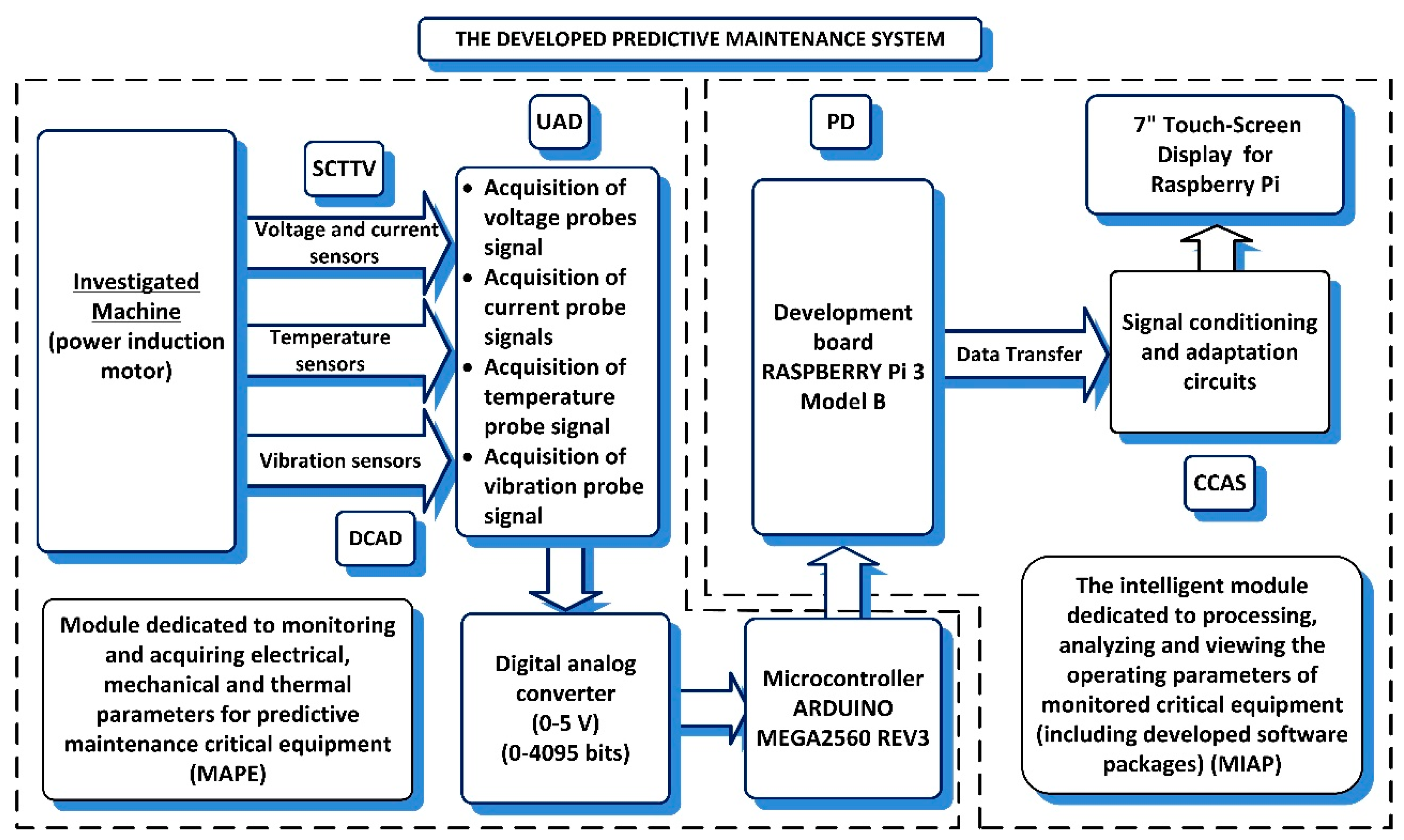
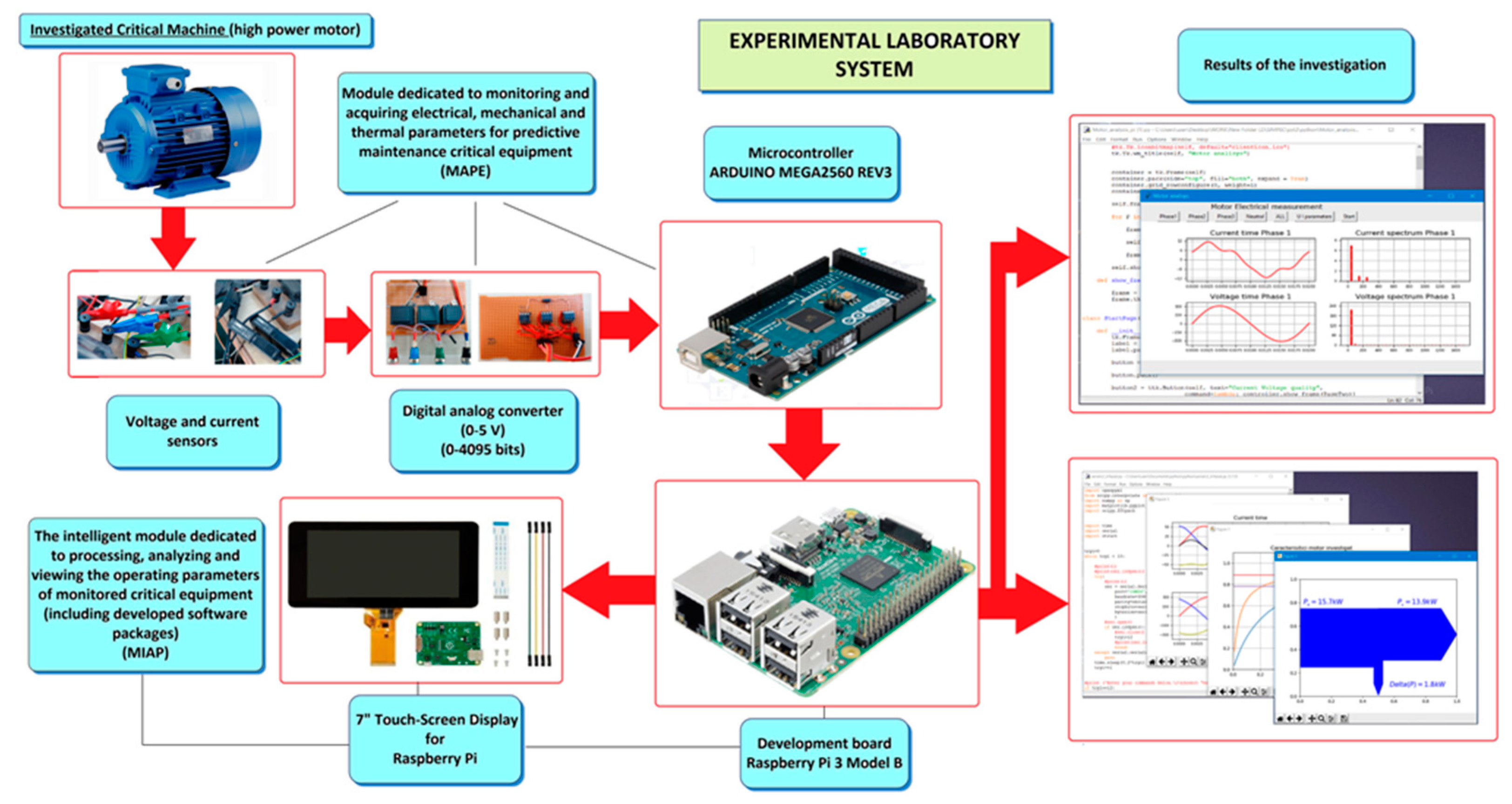
3. The Predictive Maintenance Device Design and Implementation

As already mentioned in the paper first sections, some of the most critical equipment in industrial power installations includes large electric motors. They are used to drive pumps, fans, compressors, extractors, or other various work machines of great importance for different technological processes. Therefore, these essential units require real-time predictive maintenance able to signal in advance the initiation of a potential fault. In this manner, their proper operation (with parameters within accepted limits) together with the initial lifetime expectancy is preserved.
Many industrial electrical installations users (production or operation engineers, technological engineers, or energy managers), knowing the importance of predictive maintenance for critical equipment, identified the need to develop intelligent (expert) systems capable of adequately performing this type of maintenance. This requires the adoption of an integrative predictive maintenance solution, which must meet the following design requirements:
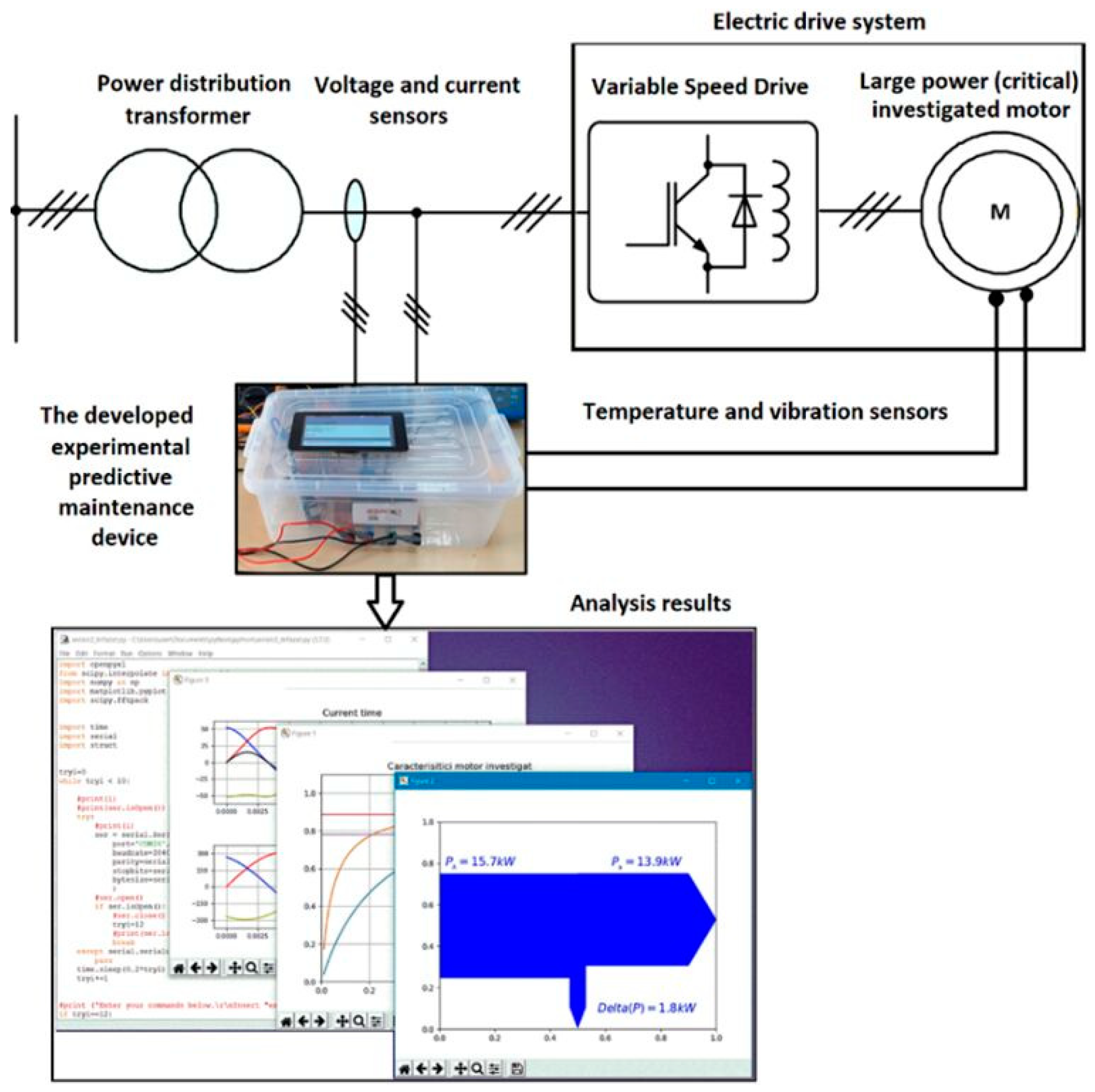
  • Continuously monitor the essential operating parameters values (electrical, thermal, and mechanical) of the investigated critical electrical equipment (motor) and to signal their deviation from the rated ones. Additionally, these abnormal variations are to be stored in a journalized manner.
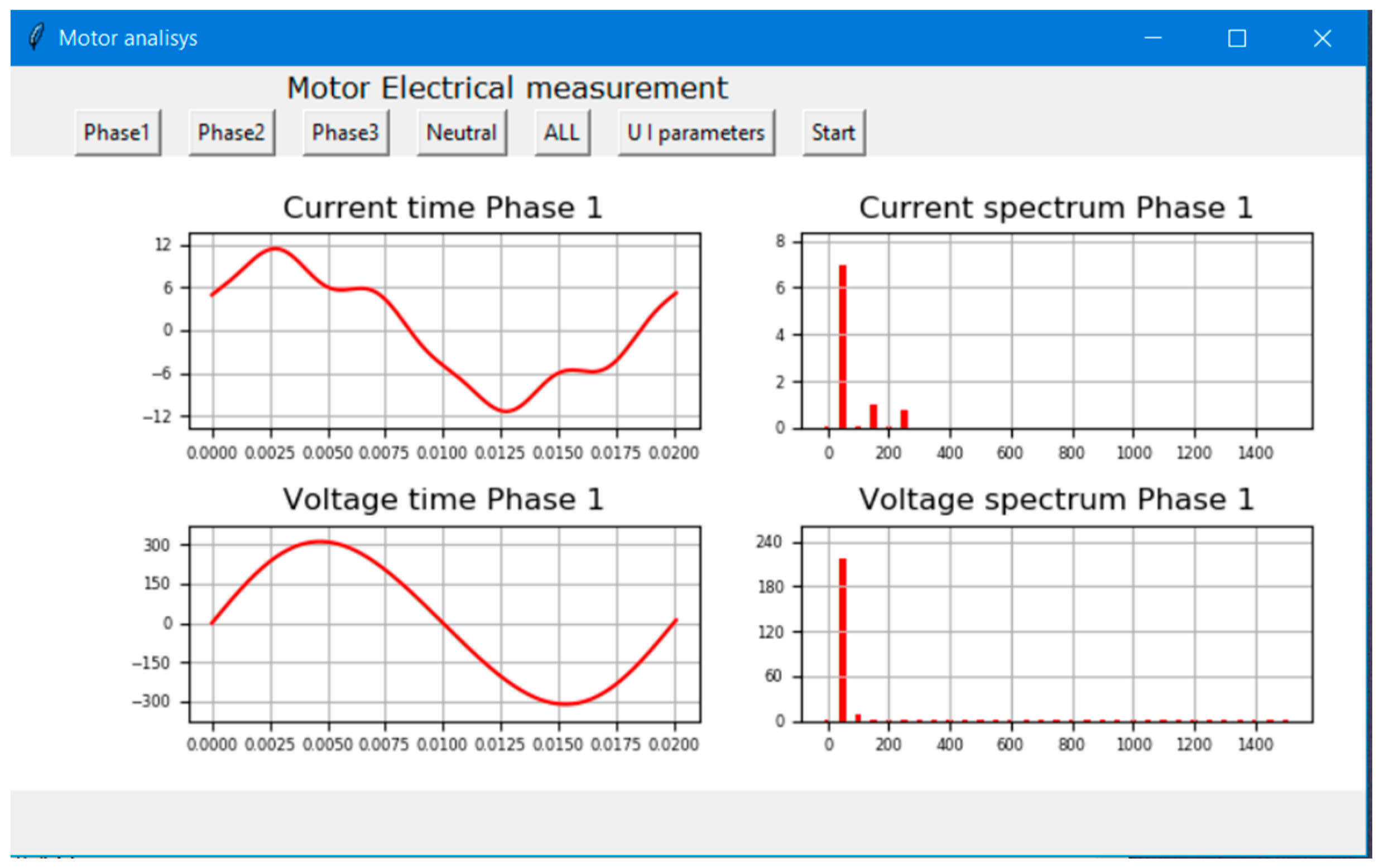
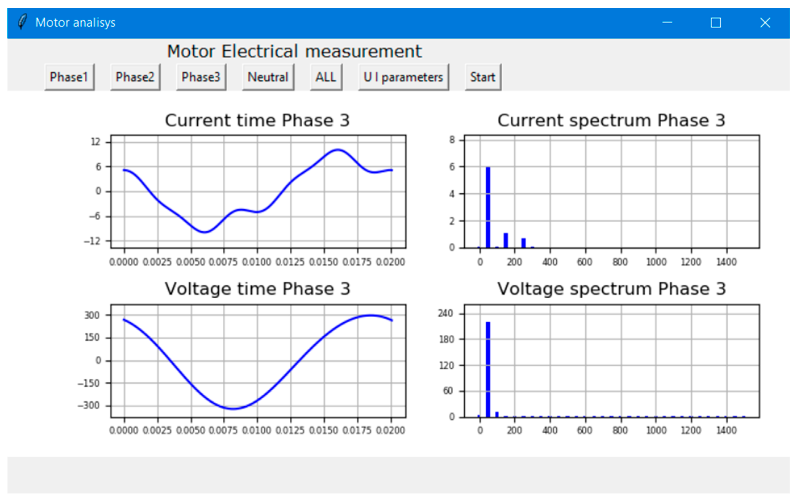
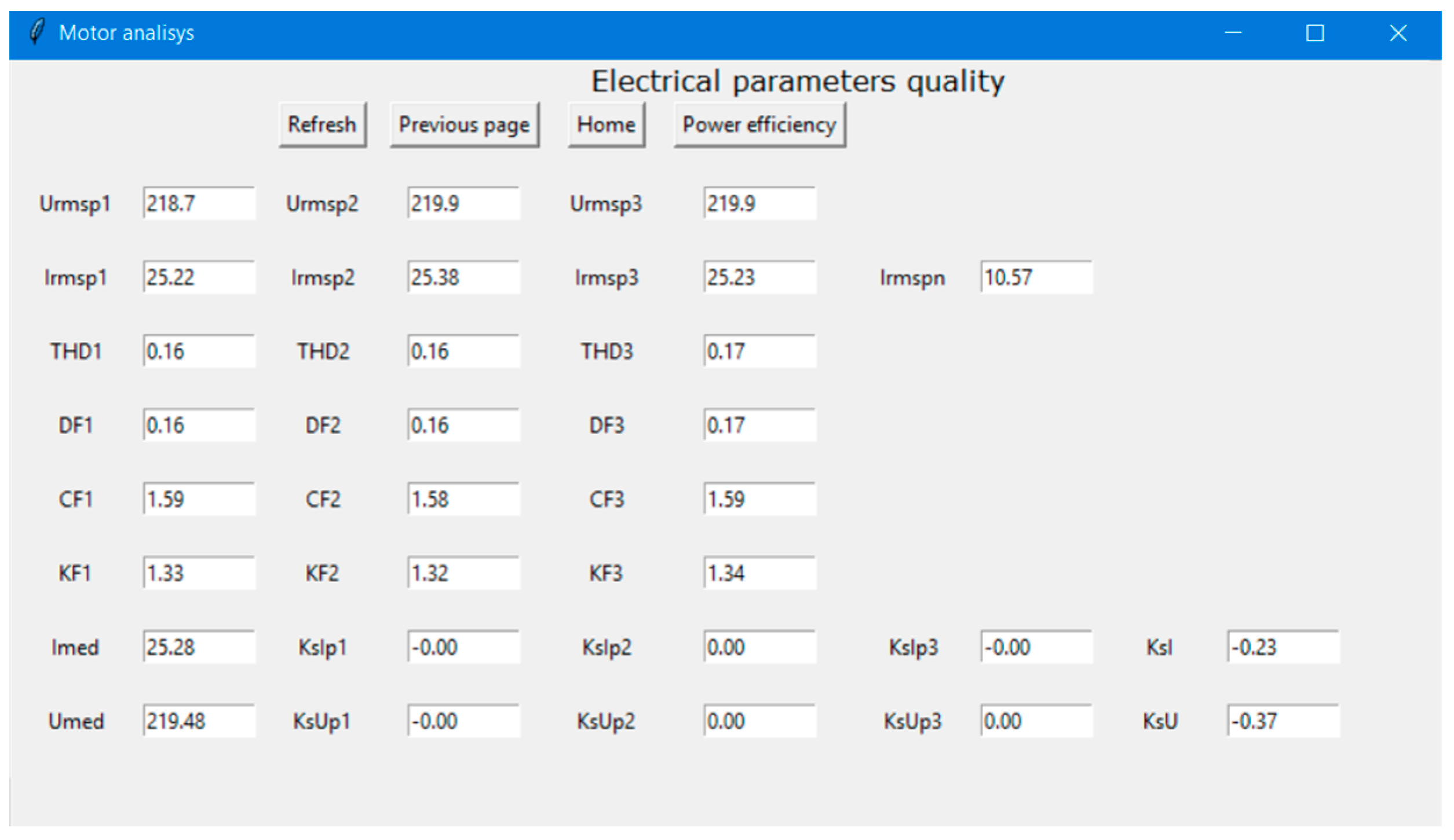
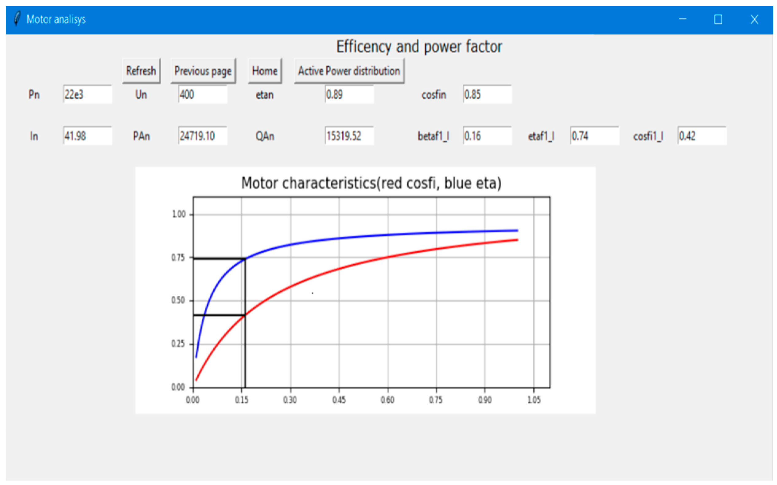
  • Facilitate a continuous determination of power quality and energy indicators of the tested equipment (voltage and current waveforms characteristics, active and reactive power distribution within the machine, operating efficiency, power factors, etc.). Thus, a maintenance report of the equipment is to be continuously generated.
  • The smart device must be also able to suggest the potential cause of the notified abnormal variations together with any remedies (if the defect is identified in a malfunction database of the developed system, constantly updated). Thus, the user of the installation could correctly address the indicated issue and consequentially maintain the continuity of the activity.
  • The device must be robust, reliable, and allow for a minimally invasive installation in the electrical installation, as the critical receivers (large power motors or machineries) rarely admit the interruption of the power supply for upgraded or improvement processes.
  • The developed intelligent system must also allow the remote transmission of the maintenance report so that it can be accessed from various locations with the help of mobile and portable communication devices (mobile phone, tablet, etc.).
Considering the demands and requirements illustrated in the previous section, an integrated predictive maintenance solution for critical equipment was developed [44]. It manages to meet the main criteria of a modern expert system.
The system is based on a simple architecture of two interconnected modules: the first one for monitoring and acquiring the power quality parameters, the temperature on the motor surface, and its vibration level (MAPE) and a second module for processing, data analysis, and visualization (MIAP)—see Figure 5.
The first module of the developed system (MAPE) uses a compact device for data acquisition (DCAD), analog and digital input-output units (UAD), sensors for current, voltage, temperature, and vibration (SCTTV), and software that allows the acquisition of data and data storage [44].
The module MAPE provides, at its terminals, electrical signals that contain information about the real-time operating parameters of the equipment under analysis (currents, voltages, temperatures, noise level, etc.). These signals are transmitted to the second smart module (MIAP), where data processing, analysis, and visualization are continuously performed. The latter consists of signal conditioning and adaptation circuits (CCAS) and a smart unit based on a development board (PD) that contains high-performance microcontrollers or digital signal controllers and the related software packages.
The implementation of the system envisages that the second module of the system (MIAP) will also facilitate the remote and real-time transmission of both the processing results (complete operation report) and the information data received from the first system module (MAPE)—the equipment operating parameters. In this way, the system is to be constantly monitored by users, regardless of their location.
The technological implementation of the MAPE module was done by current, voltage, temperature, and vibration probes, analog to digital signal processing converters and a microcontroller Arduino Mega 2560 Rev 3 type (Arduino, Torino, Italy) [45]. For the MIAP module a Raspberry Pi 3 Model B development board (Sony, Pencoed, Wales) [46] was adopted along with a dedicated 7” touchscreen display—see Figure 6.
The calculation procedures for the investigated energy parameters of the motors as well as those necessary for the interpretation of the measured power quality indicators have been implemented in the Python dynamic programming language. This software easily allows the adequate programming of Raspberry Pi board development. Figure 7 shows the homepage of the developed software packages.
The input data of the developed system are mainly represented by the motor rated power and the power quality parameters measured at the tested equipment terminals. Additionally, the temperature and noise level values measured at the machine surface are also acquired. The motor circuit parameters are extracted in accordance with its rated power from a large database developed within the proposed system. This includes a large variety of low-voltage induction motors, whose parameters were provided by different manufacturers.
The developed software packages consider the usually encountered field measurement situations, and consequently, exclusively require the motor rated power (indicated in kW). Subsequently, the database is accessed, and a generic motor is used for further computation. Thus, the motor circuit parameters are approximated in an acceptable manner. A more accurate determination is obtained if all the data for the examined motor are available from the machine manufacturer (a very infrequent condition).

4. Discussions

Figure 8, Figure 9, Figure 10, Figure 11, Figure 12 and Figure 13 illustrate captures of the various software modules developed to perform the determination, visualization, and non-invasive analysis of the in-service critical equipment (motor) under investigation. The developed system performs a continuous assessment of the essential operating parameters (electrical, thermal, and mechanical) of the investigated equipment and real-time signaling of deviation from their nominal values. It also suggests the potential cause of these abnormal variations along with possible remedies.
Thus, one can notice from Figure 8, Figure 9 and Figure 10 that the device allows the visualization of the motor phase waveforms and the computes the corresponding harmonic spectrum from both the voltage and the currents. Additionally, Figure 11 depicts the major power quality parameters associated with the harmonic distortions these waveforms. They are critically interpreted by the device and when they are exceeded (relative to the rated values, established by the standards) is immediately signaled and some possible solutions are suggested [30,31,32].
The here-presented smart predictive maintenance device also manage to evaluate the energetical aspects of the inspected operation motor. Therefore, Figure 12 presents the computed power factor and energy efficiency as a function of the motor load (defined as the measured active power relative to its rated one). These visualized characteristics can be very useful in establishing the motor adaptation to the load along with operating efficiency and power factor variations. Supplementary, the active power flow within the motor and its corresponding Sankey diagram is illustrated in Figure 13. This also represents a very intuitive way to indicate the motor active power usage and to immediately regard its current efficiency [35,38,39].
The developed functional model could allow predictive maintenance of other equipment (even small installations—machine circuits) that have a neutral conductor (the system is also equipped with clamps for measuring the current on the neutral conductor and the voltage between the protection PE and neutral conductor N). In this way, the use of the developed system is not intended exclusively for asynchronous motors. This could be especially useful for investigating distribution systems with neutral conductors that supply balanced and unbalanced single-phase non-linear loads. In these situations, the overloading of the neutral conductor is to be expected (especially for old in-service electric installations) due to the third harmonic attendance in the phase current load harmonic spectrum [24].
Due to the compact way in which the experimental device was designed, it proved to be a very reliable and robust system during the numerous laboratory tests. Furthermore, the device showed that it can operate under difficult environment conditions. The relatively small size of the system also allows its integration into other non-invasive predictive maintenance chains. Remote transmission of the investigated results can also be simply facilitated. The low cost of the here-developed maintenance equipment makes it also easy to implement in an industrial product.
The realization of the intelligent predictive maintenance system for critical in-service motors is indicated in Figure 14.
One can notice that the maintenance device was only manufactured with simple common low-costs components. In this manner, this equipment has the most important advantage relative to other maintenance system offered by various manufacturers—its very low production price. This affordability could be exploited by any small production facility, where the acquisitions of any commercial maintenance devices is, due to financial reasons, disregarded [9,11,14].
Figure 15 shows the simple way to connect the device to the terminals of an investigated motor. This non-invasive easy installation also represents a major advantage of the equipment since many of the inspected motors are in-service and their disconnection from the power supply source is not allowed due to the supplied technological process.
It is important to mention that the device has also some limitations regarding the computation of motor energetical parameters that could operate under unbalanced and/or distortion conditions. They are mainly derived from the fact that the adopted circuit model for the motor main operating computations parameters is valid under rated conditions (being supplied from a balanced and pure sinusoidal voltage source) [38,39,40]. Unfortunately, these conditions are rarely met in the field measurements. This is another reason why this novel smart maintenance device was also designed (to signal these issues too). Nevertheless, the indicated results of the equipment that are accurate only under rated conditions do represent a relevant portrait of the motor operation under any state and the equipment is a useful tool for preserving its lifetime operation.

5. Conclusions

The paper proposed an advanced predictive maintenance tool for critical equipment found in modern electrical installations. Thus, an intelligent and minimally invasive predictive maintenance system is designed. The developed maintenance system signals in advance the possibility of a defect, suggesting its causes and possible remedies (if the improper operation is found in the database of fault causes, a database that is always updated upon the occurrence of a new malfunction, later addressed).
The system continuously generates an operating report of the analyzed equipment, detailing the trend of the power quality indicators, the surface temperature variation of the inspected equipment, as well as its vibration level.
The novel device is also an alternative solution to the usage of numerous comprehensive measurement instruments that do not allow an immediate and on-site integrative analysis of the measured parameters. The system simple architecture ensures its high robustness and reliability. In addition, its high technical performance combined with low manufacturing costs makes it a competitive commercial product. Additionally, the device facilitates the remote transmission of investigated results.
Unlike the commercial predictive maintenance solutions, the proposed device manages to be affordable and very flexible and can be easily (or simply) adapted for a large variety of equipment under surveillances (not necessarily motors). Additionally, its connectivity schematics facilitates the investigations of critical equipment supplied from all low-voltage utility distribution network (TNC, TNC-S, IT, and TT). These significant advantages cope the current demands regarding the price and versatility of such expert systems.
The here-presented predictive maintenance system can be improved both in terms of its accuracy and applicability in at least two significant areas:
  • Improving the computation procedure of the examined motor operational energetical parameters. This demands the considerations of other essential power quality parameters that define the motor functionality under other states, e.g., unbalanced or distorted states, which are often encountered in low-voltage installations. Additionally, the motor transients are also to be investigated by this maintenance device, since during the switching processes, the electric and mechanical stresses within the machine are considerable and could endanger the motor’s operation after the transient decay.
  • Developing a better determination of the motor circuit parameter. This could be achieved by adopting an advanced motor model that also requires construction and material data of the machine and the usage of various numerical methods in developing the improved circuit model. Thus, the concept of the “generic” motor is to be updated also by periodically acquiring supplementary data from various motor manufacturers.
Since in numerous inspected electrical installations (old and new), many types of critical low-voltage equipment (motors) are not foreseen with any predictive maintenance tool, the here-presented device could be an affordable solution for performing this important service.

Author Contributions

Conceptualization, E.C. and L.-G.P.; methodology, E.C.; software, E.C.; validation, V.I. and E.C.; investigation, E.C., L.-G.P. and V.I.; writing—original draft preparation, E.C.; writing—review and editing, L.-G.P. and V.I. All authors have read and agreed to the published version of the manuscript.

Funding

This work has been supported by the “Programul Operațional Competitivitate-Competitiveness Operational Program-2014–2020” and “Acțiune 1.2.1”, through the project (ID/Cod My SMIS) 121611, contract number 273/24.06.2020 (acronym: SIPAMASRE).

Data Availability Statement

Not applicable.

Acknowledgments

The device was developed due to the research project “Intelligent system of predictive maintenance for critical industrial electrical equipments” (PN-III-P2-2.1-CI-2018-1220/204CI-25.07.2018).

Conflicts of Interest

The authors declare no conflict of interest.

References

  1. Hashemian, H.M.; Bean, W.C. State-of-the-Art Predictive Maintenance Techniques. IEEE Trans. Instrum. Meas. 2010, 60, 226–236. [Google Scholar] [CrossRef]
  2. Gono, R. Reliability and maintenance of electrical power system: Invited lecture. In Proceedings of the 18th International Scientific Conference on Electric Power Engineering (EPE), Kouty nad Desnou, Czech Republic, 17–19 May 2017; pp. 1–4. [Google Scholar] [CrossRef]
  3. Manjare, A.A.; Patil, B.G. A Review: Condition Based Techniques and Predictive Maintenance for Motor. In Proceedings of the 2021 International Conference on Artificial Intelligence and Smart Systems (ICAIS), Coimbatore, India, 25–27 March 2021; pp. 807–813. [Google Scholar] [CrossRef]
  4. Goundar, S.S.; Pillai, M.R.; Mamun, K.A.; Islam, F.R.; Deo, R. Real time condition monitoring system for industrial motors. In Proceedings of the 2nd Asia-Pacific World Congress on Computer Science and Engineering (APWC on CSE), Nadi, Fiji, 2–4 December 2015; pp. 1–9. [Google Scholar] [CrossRef]
  5. Cazacu, E.; Petrescu, L.; Petrescu, M.C. The major predictive maintenance actions of the electric equipments in the industrial facilities. Sci. Bull. Electr. Eng. Fac. 2018, 18, 26–33. [Google Scholar] [CrossRef] [Green Version]
  6. Janssens, O.; Loccufier, M.; van Hoecke, S. Thermal Imaging and Vibration-Based Multisensor Fault Detection for Rotating Machinery. IEEE Trans. Ind. Inform. 2018, 15, 434–444. [Google Scholar] [CrossRef] [Green Version]
  7. Alfredo Osornio-Rios, R.; Antonino-Daviu, J.A.; de Jesus Romero-Troncoso, R. Recent Industrial Applications of Infrared Thermography: A Review. IEEE Trans. Ind. Inform. 2018, 15, 615–625. [Google Scholar] [CrossRef]
  8. Novoa, C.G.; Berríos, G.A.G.; Söderberg, R.A. Predictive maintenance for motors based on vibration analysis with compact rio. In Proceedings of the 2017 IEEE Central America and Panama Student Conference (CONESCAPAN), Panama, Panama, 20–22 September 2017; pp. 1–6. [Google Scholar] [CrossRef]
  9. Lu, B.; Durocher, D.B.; Stemper, P. Predictive maintenance techniques. IEEE Ind. Appl. Mag. 2009, 15, 52–60. [Google Scholar] [CrossRef]
  10. Rahm, L.; Lorenz, J.; Khaydarov, V.; Maywald, T.; Glas, T.; Urbas, L. Predictive maintenance with NOA: Application and insights for rotating equipment. In Proceedings of the 2020 25th IEEE International Conference on Emerging Technologies and Factory Automation (ETFA), Vienna, Austria, 8–11 September 2020; pp. 761–767. [Google Scholar] [CrossRef]
  11. Al-Mansour, A.; Lee, K.-W.W.; Al-Qaili, A.H. Prediction of Pavement Maintenance Performance Using an Expert System. Appl. Sci. 2022, 12, 4802. [Google Scholar] [CrossRef]
  12. Jones, G.; Frost, N. Introduction to Predictive Models for Motor Dielectric Aging. In Proceedings of the 2020 IEEE Electrical Insulation Conference (EIC), Knoxville, TN, USA, 22 June 2020–3 July 2020; pp. 282–285. [Google Scholar] [CrossRef]
  13. Zhang, S.; Wang, B.; Kanemaru, M.; Lin, C.; Liu, D.; Miyoshi, M.; Teo, K.N.; Habetler, T.G. Model-Based Analysis and Quantification of Bearing Faults in Induction Machines. IEEE Trans. Ind. Appl. 2020, 56, 2158–2170. [Google Scholar] [CrossRef]
  14. Antonino-Daviu, J.; Dunai, L.; Climente-Alarcon, V. Design of innovative laboratory sessions for electric motors predictive maintenance teaching. In Proceedings of the IECON 2017-43rd Annual Conference of the IEEE Industrial Electronics Society, Beijing, China, 29 October–31 November 2017; pp. 3965–3970. [Google Scholar] [CrossRef]
  15. Baklouti, A.; Mifdal, L.; Dellagi, S.; Chelbi, A. An Optimal Preventive Maintenance Policy for a Solar Photovoltaic System. Sustainability 2020, 12, 4266. [Google Scholar] [CrossRef]
  16. Sung, G.-M.; Shen, Y.-S.; Keno, L.T.; Yu, C.-P. Internet-of-Things Based Controller of a Three-Phase Induction Motor Using a Variable-Frequency Driver. In Proceedings of the 2019 IEEE Eurasia Conference on IOT, Communication and Engineering (ECICE), Yunlin, Taiwan, 3–6 October 2019; pp. 156–159. [Google Scholar] [CrossRef]
  17. Penrose, H.W. Simple Time-to-Failure Estimation Techniques for Reliability and Maintenance of Equipment. IEEE Electr. Insul. Mag. 2009, 25, 14–18. [Google Scholar] [CrossRef]
  18. Jung, J.; Lee, J.; Kwon, B. Online Diagnosis of Induction Motors Using MCSA. IEEE Trans. Ind. Electron. 2006, 53, 1842–1852. [Google Scholar] [CrossRef]
  19. Mariut, L.; Filip, M.; Helerea, E.; Peter, I. Analysis and modeling on the induction machine faults. In Proceedings of the 3rd International Symposium on Electrical and Electronics Engineering (ISEEE), Galati, Romania, 16–18 September 2010; pp. 11–16. [Google Scholar] [CrossRef]
  20. Paun, A.; Vinga, C.M.; Frigura-Iliasa, F.M.; Vatau, D.; Cazacu, E.; Petrescu, L. Study about the active power and energy losses of a 400V 57 kW asynchronous motor. In Proceedings of the 19th International Scientific Conference on Electric Power Engineering (EPE), Brno, Czech Republic, 16–18 May 2018; pp. 1–4. [Google Scholar] [CrossRef]
  21. Cazacu, E.; Năvrăpescu, V.; Nemoianu, I.V. On-site efficiency evaluation for in-service induction motors. Rev. Roum. Sci. Techn. Électrotechn. et Énerg. 2013, 58, 63–72. [Google Scholar]
  22. Baurand, G.; Moliton, V. The Protection of LV Motors, Schneider Electric. Cahier Technique, no. 211. 2002. Available online: https://www.se.com/lt/lt/download/document/ECT211/ (accessed on 2 May 2022).
  23. Glen, A.M.; Weindorf, W.J. Electric Motor Drive Installation and Troubleshooting, 3rd ed.; American Technical Pubblishers: Orland Park, IL, USA, 2015. [Google Scholar]
  24. Ferracci, P.H. Power quality, Schneider Electric. Cahier Technique. no. 199. 2001. Available online: https://www.se.com/au/en/download/document/ECT199/ (accessed on 2 May 2022).
  25. Melani, A.H.A.; Murad, C.A.; Caminada Netto, A.; Souza, G.F.M.; Nabeta, S.I. Maintenance Strategy Optimization of a Coal-Fired Power Plant Cooling Tower through Generalized Stochastic Petri Nets. Energies 2019, 12, 1951. [Google Scholar] [CrossRef] [Green Version]
  26. Orság, P.; Kocman, S.; Otýpka, J. Impact of mains power quality on operation characteristics of induction motor. In Proceedings of the 2014 14th International Conference on Environment and Electrical Engineering, Krakow, Poland, 10–12 May 2014; pp. 382–385. [Google Scholar] [CrossRef]
  27. Peter, A.A.; Okakwu, I.K.; Olowasogo, E.S.; Alayande, A.S.; Airoboman, A.E. Influence of Power Quality Problem on the Performance of an Induction Motor. Am. J. Electr. Power Energy Syst. 2015, 4, 39–44. [Google Scholar] [CrossRef]
  28. Neves, A.B.F.; Filho, A.d.L.F.; de Mendonça, M.V.B. Effects of voltage unbalance on torque and efficiency of a three-phase induction motor. In Proceedings of the 16th International Conference on Harmonics and Quality of Power (ICHQP), Bucharest, Romania, 25–28 May 2014; pp. 679–683. [Google Scholar] [CrossRef]
  29. De Castro e Silva, M.D.; Ferreira Filho, A.L.; Neves, A.B.F.; Mendonça, M.V.B. Effects of sequence voltage components on torque and efficiency of a three-phase induction motor. Electric Power Syst. Res. 2016, 140, 942–949. [Google Scholar] [CrossRef]
  30. Duque-Perez, O.; Morinigo-Sotelo, D.; Perez-Alonso, M. Diagnosis of induction motors fed by supplies with high harmonic content using motor current signature analysis. In Proceedings of the International Conference on Power Engineering, Energy and Electrical Drives, Malaga, Spain, 11–13 May 2011; pp. 1–6. [Google Scholar] [CrossRef]
  31. Deraz, S.A.; Azazi, H.Z. Impact of distorted voltage on three-phase induction motor performance. In Proceedings of the Nineteenth International Middle East Power Systems Conference (MEPCON), Cairo, Egypt, 19–21 December 2017; pp. 857–863. [Google Scholar] [CrossRef]
  32. Donolo, P.D.; Pezzani, C.M.; Bossio, G.R.; de Angelo, C.H.; Donolo, M.A. Derating of Induction Motors Due to Power Quality Issues Considering the Motor Efficiency Class. IEEE Trans. Ind. Appl. 2020, 56, 961–969. [Google Scholar] [CrossRef]
  33. Babaa, F.; Bennis, O. Steady State Analytical Study of Stator Current Harmonic Spectrum Components on Three-Phase Induction Motor under Unbalanced Supply Voltage. In Proceedings of the International Conference on Control, Automation and Diagnosis (ICCAD), Paris, France, 7–9 October 2020; pp. 1–6. [Google Scholar] [CrossRef]
  34. Chauhan, S.; Singh, S.B. Effects of Voltage Unbalance and Harmonics on 3-Phase Induction Motor During the Condition of Undervoltage and Overvoltage. In Proceedings of the 6th International Conference on Signal Processing and Integrated Networks (SPIN), Noida, India, 7–8 March 2019; pp. 1141–1146. [Google Scholar] [CrossRef]
  35. Al-Badri, M.; Pillay, P.; Angers, P. A Novel in Situ Efficiency Estimation Algorithm for Three-Phase Induction Motors Operating with Distorted Unbalanced Voltages. IEEE Trans. Ind. Appl. 2017, 53, 5338–5347. [Google Scholar] [CrossRef]
  36. Silwal, B.; Mohamed, A.H.; Nonneman, J.; de Paepe, M.; Sergeant, P. Assessment of Different Cooling Techniques for Reduced Mechanical Stress in the Windings of Electrical Machines. Energies 2019, 12, 1967. [Google Scholar] [CrossRef] [Green Version]
  37. Ching-Yin, L. Effects of unbalanced voltage on the operation performance of a three-phase induction motor. IEEE Trans. Energy Convers. 1999, 14, 202–208. [Google Scholar] [CrossRef]
  38. Van Wyk, A.L.; Khan, M.A.; Barendse, P. Impact of over/under and voltage unbalanced supplies on energy-efficient motors. In Proceedings of the IEEE International Electric Machines & Drives Conference (IEMDC), Niagara Falls, ON, Canada, 15–18 May 2011; pp. 1380–1385. [Google Scholar] [CrossRef]
  39. Faiz, J.; Ebrahimpour, H.; Pillay, P. Influence of unbalanced voltage on the steady-state performance of a three-phase squirrel-cage induction motor. IEEE Trans. Energy Convers. 2004, 19, 657–662. [Google Scholar] [CrossRef]
  40. Donolo, P.; Bossio, G.; de Angelo, C.; García, G.; Donolo, M. Voltage unbalance and harmonic distortion effects on induction motor power, torque and vibrations. Electric Power Syst. Res. 2016, 140, 866–873. [Google Scholar] [CrossRef]
  41. IEC TS 60034-25:2014; Rotating Electrical Machines—Part 25: AC Electrical Machines Used in Power Drive Systems—Application Guide. 2014. Available online: https://webstore.iec.ch/publication/128 (accessed on 2 May 2022).
  42. IEC 61000-4-30:2015+AMD1:2021; CSV Consolidated Version. Electromagnetic Compatibility (EMC)—Part 4-30: Testing and Measurement Techniques—Power Quality Measurement Methods. 2021. Available online: https://webstore.iec.ch/publication/65716 (accessed on 2 May 2022).
  43. IEEE Std. 1459-2010; Standard Definitions for the Measurement of Electric Power Quantities Under Sinusoidal, Nonsinusoidal, Balanced, or Unbalanced Conditions. IEEE: New York, NY, USA, 2010.
  44. Cazacu, E. Research report nr. 1PN-III-P2-2.1-CI-2018-1220/204CI—25.07.2018. Intelligent System of Predictive Maintenance for Critical Industrial Electrical Equipments. 2018. Available online: http://www.simpec.elth.pub.ro/index.html (accessed on 2 May 2022).
  45. Available online: https://store.arduino.cc/arduino-mega-2560-rev3 (accessed on 2 May 2022).
  46. Available online: https://www.raspberrypi.org/products/raspberry-pi-3-model-b/ (accessed on 2 May 2022).
Figure 1. Pareto chart for electrical motor defects.
Energies 15 04283 g001
Figure 2. Impact of the motor winding temperature over the motor electric isolation resistance (a) and its lifetime operation (b).
Energies 15 04283 g002
Figure 3. The motor derating factor (a) and the corresponding operating efficiency under voltage distortion condition (b).
Energies 15 04283 g003
Figure 4. The unbalance voltage waveforms that supply and the motor (a) and the unbalance derating factor (b).
Energies 15 04283 g004
Figure 5. Block diagram of the smart predictive maintenance device.
Energies 15 04283 g005
Figure 6. Physical implementation of the smart predictive maintenance system dedicated to critical in-service motors.
Energies 15 04283 g006
Figure 7. Homepage of the developed software package.
Energies 15 04283 g007
Figure 8. The visualization of the waveforms and harmonic spectrum of voltage and current in Phase 1.
Energies 15 04283 g008
Figure 9. The visualization of the waveforms and harmonic spectrum of voltage and current in Phase 2.
Energies 15 04283 g009
Figure 10. The visualization of the waveforms and harmonic spectrum of voltage and current in Phase 3.
Energies 15 04283 g010
Figure 11. The major voltage and current power quality parameters measured at the investigated equipment terminals.
Energies 15 04283 g011
Figure 12. Computation of the monitored equipment instant efficiency and power factor along with their load characteristics.
Energies 15 04283 g012
Figure 13. Active power flow within the inspected electric motor and its corresponding Sankey diagram.
Energies 15 04283 g013
Figure 14. The realization of the intelligent predictive maintenance system for critical in-service motors.
Energies 15 04283 g014
Figure 15. The connection of the developed device to the terminals of an investigated in-service motor.
Energies 15 04283 g015
Publisher’s Note: MDPI stays neutral with regard to jurisdictional claims in published maps and institutional affiliations.

