Article

Reduction of the Electromagnetic Torque Oscillation during the Direct on Line (DOL) Starting of a 6 kV Motor by Means of a Controlled Vacuum Circuit-Breaker

by
Zbigniew Kłosowski
*,
Maciej Fajfer
and
Zbigniew Ludwikowski
Institute of Electrical Engineering, Faculty of Telecommunications, Computer Science and Electrical Engineering, Bydgoszcz University of Science and Technology, 85-796 Bydgoszcz, Poland
*
Author to whom correspondence should be addressed.
Energies 2022, 15(12), 4246; https://doi.org/10.3390/en15124246
Submission received: 3 May 2022 / Revised: 3 June 2022 / Accepted: 7 June 2022 / Published: 9 June 2022
(This article belongs to the Section F: Electrical Engineering)

Abstract

:
This article deals with the issue of the reduction of the oscillation of electromagnetic torque in the case of a direct on line (DOL) starting of a 6 kV induction motor. Such engines are used in drive systems where frequent starting may be required. Direct starting in such systems may reduce the mechanical and thermal durability. Therefore, the article presents a method of DOL starting of a 6 kV induction motor with the use of vacuum circuit-breakers and appropriate switching of the voltages supplying the electric machine. To confirm the advantages of the proposed solution, computer simulation and experimental tests were carried out, which are presented and discussed in the article. The obtained results confirm the advantages of the proposed solution, compared to the classic starting known from the literature.

1. Introduction

There is a large number of electric drives with squirrel cage induction motor operating in medium-voltage industrial grids (6 kV). In the vast majority of applications, there is no need for smooth speed or torque control, so the drives use direct on line starting (DOL), without power electronic converter and soft-starts method. The most common solution here is the application of electromechanical switches. In many cases, several to several dozen DOL starts are required during the day. There are two major operational problems in this type of drive system. The first problem is related to the flow of current of much greater intensity (relative to the rated current of the motor) during the DOL start. For the operation of the motor with frequent starts, it is appropriate to take into account the thermal effects in the motor’s windings. The second problem, very rarely considered in the literature, is the electromagnetic torque oscillations during DOL starting. This results in oscillations of the electrodynamic torque in the rotor, clutch and driven machine (e.g., fan drive). In the rotational speed waveform during DOL starting, brakings occur, and as a consequence, vibrations and faster wear of the mechanical elements of the system.
Power electronic converters are widely used in electric drives with squirrel cage induction motors. They allow you to control the operation of the engines, including during their starting. The authors of the article pay attention to such electric drives where the high starting current value is not a problem and the motor operation control is not required. These types of drives are powered directly from the network, and the switching processes are carried out with contact switches (without power electronic devices). The starting takes place through the direct connection (only through the connector contacts) of the winding terminals to the power supply network. In these cases, oscillations of the electromagnetic torque of the motor occur, which translates into deceleration of the rotor speed, followed by noise and faster wear of the mechanical components of the drive. The waveforms of dynamic torques occurring during the direct starting of induction motors are well known.
Figure 1 shows the known waveforms of the electromagnetic torque and rotor speed, as well as the dynamic mechanical characteristics of a squirrel-cage induction motor (11 kW rated power) during the classic direct start-up (motor without load). The presented diagrams show rotor braking and significant oscillations of the electromagnetic moment, and thus the dynamic one, characteristic for the classic direct starting method. Practitioners know very well that these are unfavorable phenomena that cause mechanical vibrations.
The authors of the article dealt with precisely this type of drive, in which there is no need to use power electronic converters. They propose an original way of switching induction motors on with a special contact switch, in which two contact sections switch on in a controlled manner. The proposed new method reduces the oscillations of the electromagnetic torque of the motor and ensures a dynamically smooth, i.e., without braking the rotor, starting process. For example, Figure 2 shows the results of simulation tests of a new method of direct starting of induction motors.
The comparison of the presented waveforms of the electromagnetic torque and rotor speed, as well as the dynamic mechanical characteristics with the results presented in Figure 1, confirm the thesis that there is a simple way to reduce the oscillation of the electromagnetic torque of the motor during direct start-up (without power electronic converters), which translates into limiting the mechanical vibrations of the drive.
The physical context of the problem of electromagnetic torque oscillation during direct starting was described in publication [1] in 2003. This publication proposes a method of limiting the oscillation of the electromagnetic torque in low voltage (LV) squirrel cage induction motors, the effectiveness of which has been confirmed experimentally. Controlled thyristor switches were used in that experiment. The effectiveness of the proposed method has been experimentally confirmed, but in technical terms, the use of power electronic switches is not satisfactory for the operators of this type of electric drive.The emerging current surge during DOL starting increases the thermal and electrodynamic effects on the engine structure. The inrush current flow results in electromagnetic forces acting on the stator winding and rotor cage, and the rapid heating of these windings. Each DOL starting wears out the engine. In the first moments of starting, there are strong oscillations of the electromagnetic torque, and hence the engine torque, which cause vibrations of the entire drive unit. They cause a significant reduction in the durability of mechanical drive components, including bearings and transmission gears, cause noise harmful to human health, as well as additional losses in the engine. Occurring mechanical vibrations are mainly caused by “decelerations” (negative accelerations) of the rotor related to the oscillations of the electromagnetic torque of the motor. In paper [2], a mathematical model of the discussed phenomenon was developed and the proposed method of limiting the oscillation of the electromagnetic torque was simulated. Limiting the oscillation of the electromagnetic torque in the motor reduces or eliminates the braking of rotational speed of the rotating parts. This reduces mechanical vibrations and reduces the wear of the mechanical parts. There are many research papers published which are briefly discussed below. In analyzing the literature on this topic [3,4,5,6,7], it can be noticed that the proposed solutions for the reduction of electromagnetic torque oscillations during starting refer to an electric drive with an induction motor supplied from a low voltage network. There is a lack of methods of reducing the oscillation of the electromagnetic torque in the case of supplying medium and high power induction motors from the 6 kV medium voltage network. In [3], a method of starting a squirrel cage induction motor was proposed by connecting it to the supply network through a series connection of a resistor and a capacitor in each of the phases. It should be emphasized that this work presents only simulation results. The authors of the work [4], in order to reduce the oscillations, used thyristor switches to simultaneously switch on two phases of delaying switching on the remaining phase. However, there is no justification regarding the value of the time chosen. Moreover, in [5], a method of direct motor starting with delayed switching on of one of the phases was proposed. However, in this case, electromagnetic switches were used. The control system has been designed to take into account the times of turning on the switches. The results of laboratory tests are also presented. The paper [6] concerns the research of the thyristor soft-start system. The focus here is on eliminating torque oscillations. This was achieved by properly switching on oppositely connected thyristors during the first voltage period, after switching on the power supply. In the work [7], the thyristor method of limiting the supply voltage of an induction motor with the use of thyristor switches was used. However, the authors proposed a new control algorithm, where the angle of thyristor activation is exponentially increased. This allows the reduction of the oscillation of the torque and the inrush current value.
The aim of the work, the effects of which are presented in this article, was to develop a method of DOL starting of electric drives with 6 kV induction motors with the use of vacuum circuit breakers, which will reduce the oscillations of the electromagnetic torque in the 6 kV motor. In the study, the method described in the literature [1,2,5,8,9,10,11] was used to limit the oscillation of the electromagnetic torque. It consists of switching on one phase of the supply voltage with a delay of 5 ms. As a consequence, the starting vibrations of the drive will be limited. The article can be divided into three parts. The first part describes the method of reducing the oscillation of the electromagnetic torque, which consists of the appropriate sequence of switching on the switches supplying the panic system. The second part presents the results of a computer simulation confirming that by properly joining the switches during the DOL starting of the electric drive with a 6 kV induction motor, it will be possible to limit, among other things, the oscillation of the electromagnetic torque. On the other hand, the last part of the article presents the results of experimental studies showing the possibilities of using vacuum circuit-breakers to reduce starting vibrations.

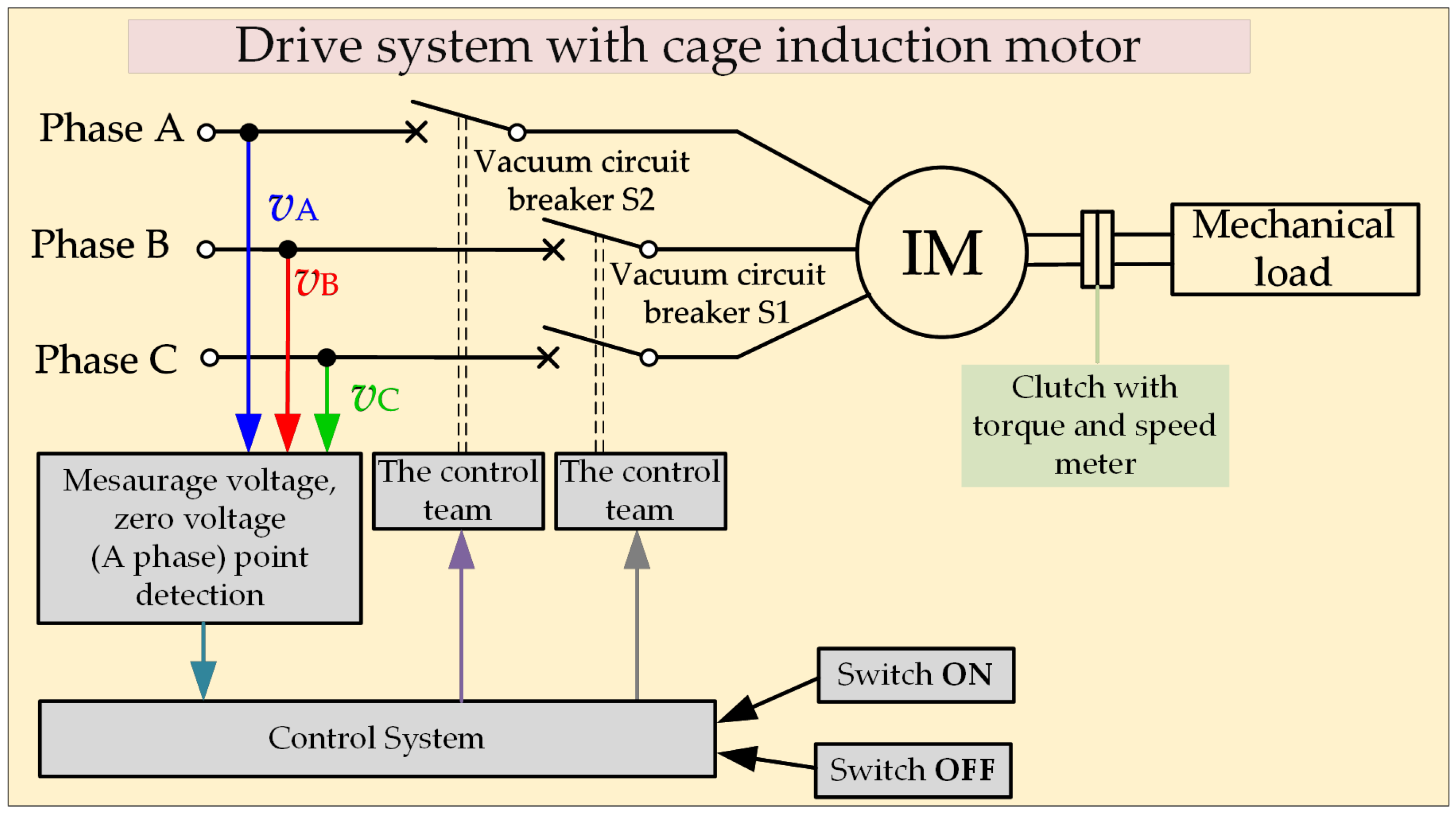
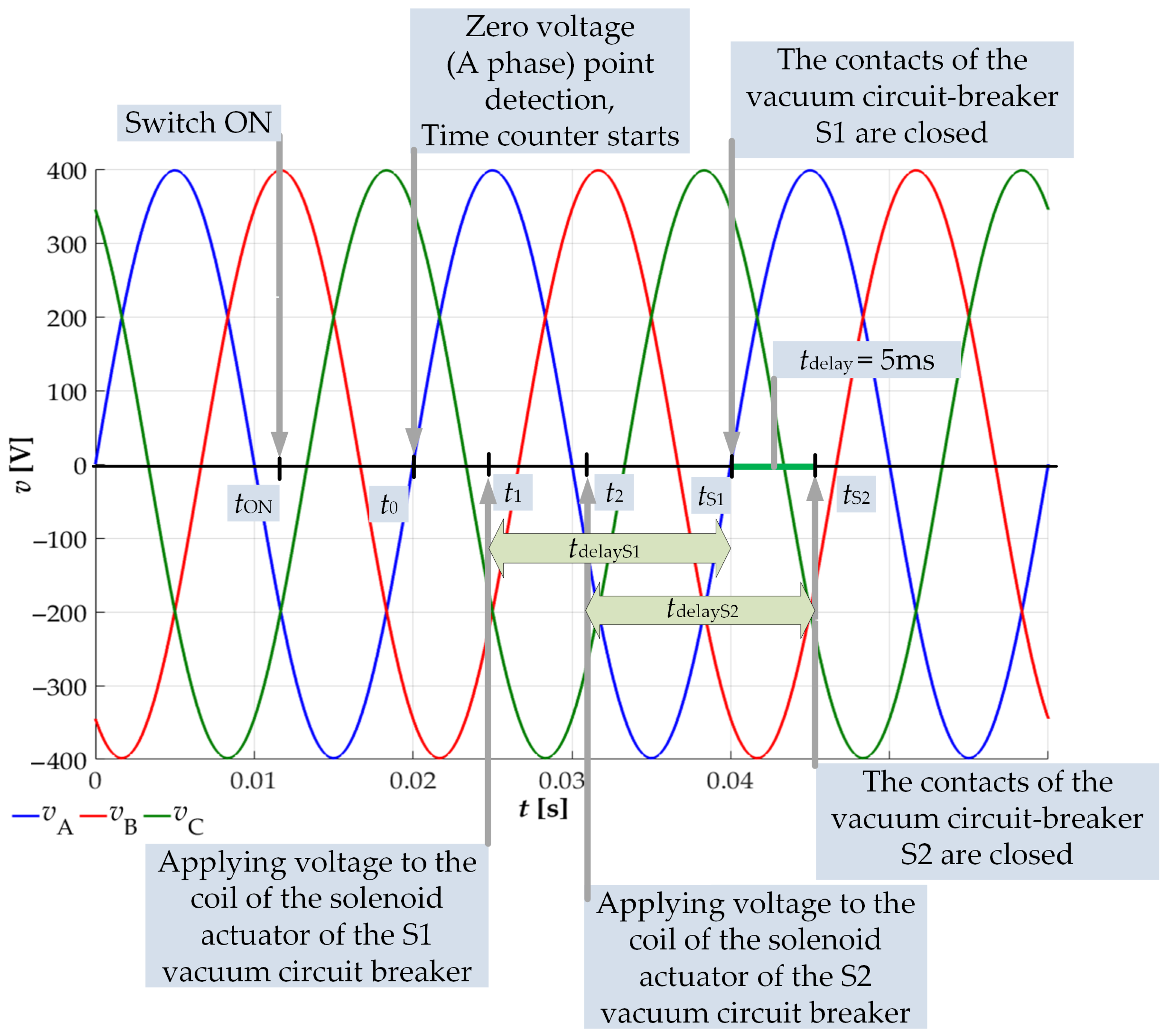
2. The Method of Minimizing the Oscillation of the Electromagnetic Torque of the Motor

During the motor starting, with the simultaneous switching of three phases, currents flow in the windings, which have two components, steady and transient. The transient component is gradually suppressed. The magnetic fields created by steady and transient currents are not generally stationary with respect to each other. The fields produced by the transient currents can amplify or weaken the main field produced by the steady currents, thereby increasing or decreasing the transient electromagnetic torque, respectively. Due to the effect of the transient currents, the magnetic fields may be directed at a certain point in such a way that the magnetic poles of the stator and the rotor adjacent to each other will repel each other and act on the rotor in the opposite direction of rotation. At this point, the electromagnetic torque of the motor becomes negative, which in turn causes the rotor to brake. This phenomenon is unfavorable because it causes a significant reduction in the durability of mechanical drive components, e.g., bearings and transmission gears, cause noise unfavorable to human health.
An effective way to limit the transient torque when starting an electric drive with induction motors is to create a flux compensating for a non-periodic flux component. Such an initial flux can be generated by switching on the supply voltages in individual phases in an appropriate procedure. The method of limiting the oscillation of the electromagnetic torque of an electric drive with an induction motor, analyzed in this work, was described in the following works [1,2,5,8,9,10,11]. The essence of the proposed procedure is the controlled delay of switching the winding of one stator phase in relation to the switching time of the windings of the other two phases. The idea of the applied method of reducing the torque oscillations during the start-up of the electromechanical system is presented in Figure 3. For this purpose, the voltage waveform should be observed, which is to be applied to the individual winding with a delay (it is assumed that the A phase voltage will be delayed), and after exceeding the zero of this voltage, voltage is applied to the stator windings of the remaining two phases (phase B and C). After the set time is 5 ms according to article [10], the phase winding in which the voltage was observed is switched on.
For the physical explanation of the phenomenon, a magnetic flux hodograph in the d-q orthogonal system was used. The simultaneous activation of the three phases causes the magnetic field of the motor to spin, which causes the torque to be applied to the rotor, which starts to move. The transient process clearly shows the transient trajectory of the main engine flux (Figure 4a), which causes oscillation of the electromagnetic moment and deceleration of the rotor speed. This process continues until the main stream enters the circular trajectory, characteristic for the steady state.
Switching on only two phases at the beginning (second phase B and third C), but when the voltage waveform of the first phase (A) crosses zero (time t 1 ), the initial trajectory of the main engine flux is not circular, therefore, it does not generate torque rotating rotor. The rotor does not move. The currents flowing through the motor windings cause an increase in the value of the main flux, which after time t 2 (¼ period of the supply voltage, for a frequency of 50 Hz it is 5 ms) reaches a value close to the value of the main flux on a circular trajectory appropriate for the main flux trajectory in steady state. If the first phase (A) is turned on at this moment, the main stream will follow this trajectory. The circular jet will create a torque on the rotor which will start to accelerate. The main stream, which theoretically moves along a circular trajectory, does not cause oscillation of the electromagnetic torque, and therefore, there is no inhibition of the rotational speed of the rotor.
If, for some reason (e.g., high magnetic inertia of the system), the main flux does not reach the value close to the value of the flux on the trajectory for the steady state (Figure 4b) at time t 2 (¼ period of voltage), then you can wait with switching on the first phase (A). After time t 2 corresponding to ¼ period, the flux value will start to decrease (Figure 4c), reaching zero after time t 3 (½ period), and after time t 4 (¾ period), the value opposite to the value of the main flux for the time corresponding to ¼ period. Note that this flux value will also be close to the flux value on the circular trajectory characteristic of the steady state. Theoretically, the first phase (A) can also be turned on at this time. If the missing phase is not turned on in this time, the flux value starts to decrease, reaching zero after the full voltage period (time t 5 ). After that, the flux starts to increase (the pulsating main flux does not make the rotor move), reaching in time t 6 corresponding to 5/4 of the voltage period, the value (for a frequency of 50 Hz it is 25 ms) will reach a value closer to the value of the main flux on the proper circular trajectory for the main stream trajectory in steady state. During this time, the third phase must be engaged. The conclusion is that for a supply voltage with a frequency of 50 Hz, the delay of switching on the third phase should be 5 ms + k · 20 ms (where: k is a positive integer, k = 0, 1, 2, 3, …). Generally, the delay can be written as T / 4 + k · T (where: T is the period of the supply voltage, k is a positive integer, k = 0, 1, 2, 3, …).
During the activation of only two phases, the classic magnetization of the motor core takes place, which does not cause the rotor to move, but sets the magnetic field in a state characteristic of a steady state. Switching on the third phase causes a circular field (appropriate for the steady state) and makes the rotor move without braking. The authors show an effective way to achieve the described process without power electronic converters, using appropriately controlled contact switches.

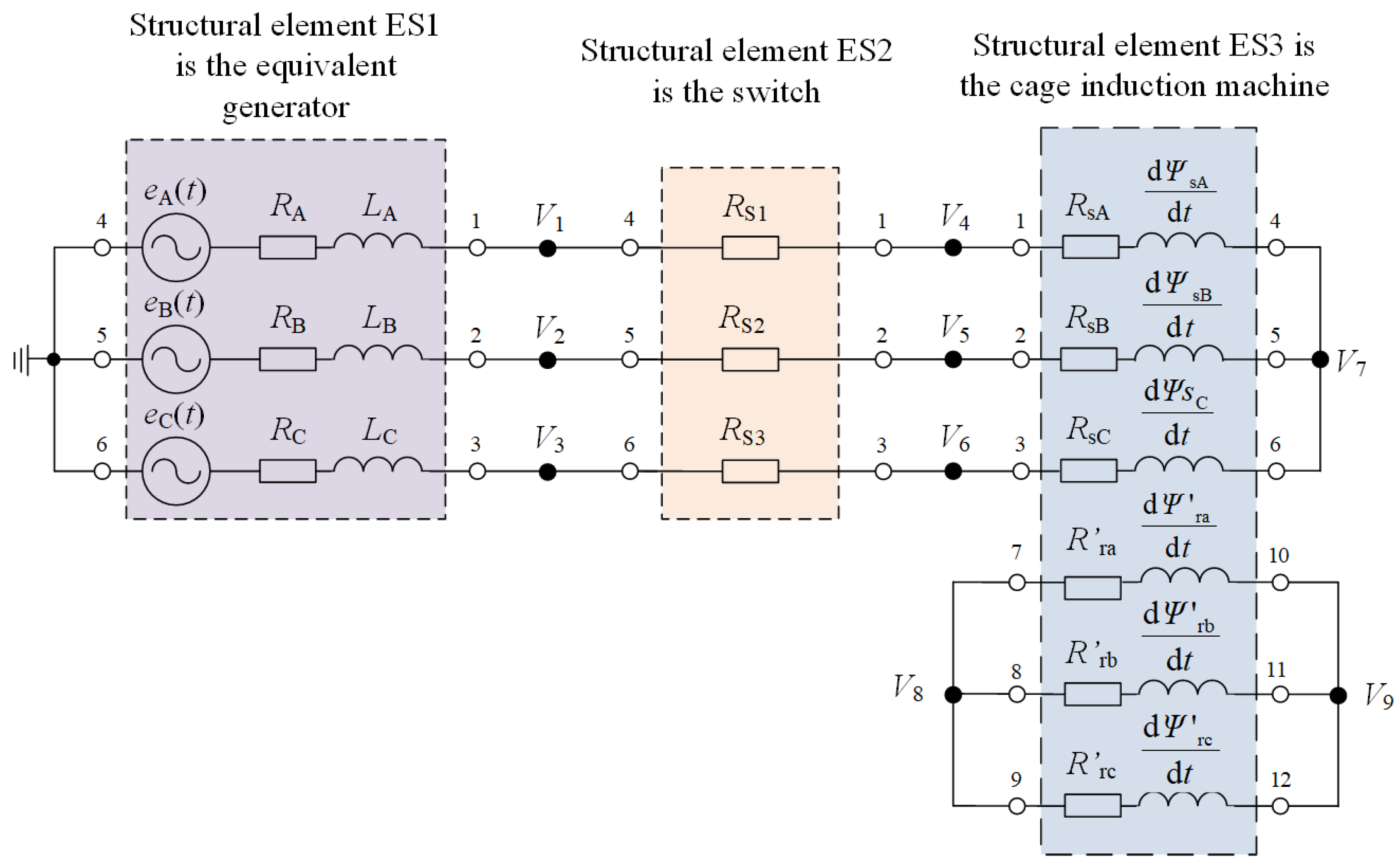
3. Mathematical Model of a Drive System with an Induction Motor

In order to confirm the effectiveness of the presented method of minimizing the oscillation of the electromagnetic torques, a computer simulation was carried out. This method was tested for the drive system with a 6 kV squirrel-cage induction motor, which is shown in Figure 5. The developed technology of switching on the induction motor was analyzed for the case when the tested machine was loaded:
  • constant torque with zero value; T o = 0 ,
  • lifting torque—resistance torque with a constant value; T o = const ,
  • fan torque—torque with a curve defined by the formula T o = T oN n n N 2 , where: T oN —resistance torque of the working machine at rated speed n = n N ,
  • fan torque with initial torque—torque with a curve defined by the formula T o = T op + T oN n n N 2 , where: T op —initial resistance torque of the working machine.
In developing the mathematical model of the system, the electric multipole method was used as a method of modeling complex electrical systems. Equivalent diagram of the power system, the test results of which are described in this section, with the division into structural elements is presented in Figure 6. The rated data of the induction motor are given in Table A1 (Appendix A).
A new approach to the approximation of differential-integral equations was used to develop a mathematical model of the drive system with an asynchronous motor. It is based on a one-step method of mathematical modeling of electrical circuits with averaging voltages at the calculation step. The basics of mathematical modeling of electrical systems with the use of the above methods are presented in detail in the article [12,13,14,15,16,17,18] written by the authors of this article. With regard to the system considered here, the following structural elements can be distinguished: an induction machine, a detailed model of which is presented in [12]; a replacement energy source (substitute generator), the detailed models of which are presented in [12]; and the connector, the model of which is presented in [12]. Performing the computer simulation it was assumed that the switch is perfect, defined only by the resistances R S 1 , R S 2 , R S 3 representing the contact resistance of the connectors of the respective phases. Depending on their position, the resistances assume the values for an open switch 100 M Ω , and for a closed switch 50 μ Ω .
Figure 7, Figure 8, Figure 9, Figure 10, Figure 11, Figure 12, Figure 13 and Figure 14 show the characteristic physical quantities of the considered processes for the SF400X6 engine and the types of loads described above. The physical quantities are: i A , i B , i C —stator currents in three phases, T —electromagnetic torque and n —rotational speed. The simulation is always performed for the DOL starting of an induction motor and for the start with reduction in the oscillation of the torque (delay of switching on the phase supplying the winding).
Comparing the stator current waveforms in three phases with DOL starting with the waveforms obtained with the voltage phase switching delay of t delay = 5 ms and at different load times, it can be noticed that the analyzed method limits the inrush current transient component (there are lower current surges during starting), which will contribute to smaller voltage drops in the path supplying the induction motor. In addition, it reduces the starting time by about 1.2 s compared to the DOL starting, which in turn will reduce the thermal and electrodynamic effects on the engine structure with frequent starting.
Next, the analysis of the trajectory of the stator flux vector during the DOL starting process and with the voltage phase switching delay of t delay = 5 ms was performed. It can be noticed that for the analyzed braking torques, the delay in switching the voltage phase on meant that the flux trajectory has a circular course. The reason for this is that at the first moment of starting, only two phases of the supply voltage are switched on, which causes the machine to generate a magnetic field (the magnetic circuit is magnetized) without generating torque. After a delay of 5 ms, the missing voltage is applied, with the consequent immediate formation of a circular magnetic field and torque generation.
Finally, the analysis of the electromagnetic torque and rotational speed waveforms was performed for the direct starting and for the voltage phase switching delay of t delay = 5 ms. In each considered case, switching on the voltage in three phases during DOL starting causes large oscillations of the electromagnetic torque, which cause high acceleration and deceleration of the rotor (vibrations caused by braking). Unfortunately, this is an undesirable phenomenon, because these vibrations cause the mechanical components of the drive to wear out faster, including bearings and transmission gears. It contributes to frequent breakdowns. With the use of DOL starting with a delay of switching on the supply phase by 5 ms, it can be said that very large oscillations of the electromagnetic torque, especially the negative torque, have been eliminated, which consequently contributed to the re-education of rotor braking (vibrations).
Simulation tests of the DOL starting of the drive system with a 6 kV squirrel-cage induction motor for the considered braking torques with a delay of switching on the supply voltage phase by 5 ms confirm the effectiveness of the tested solution.

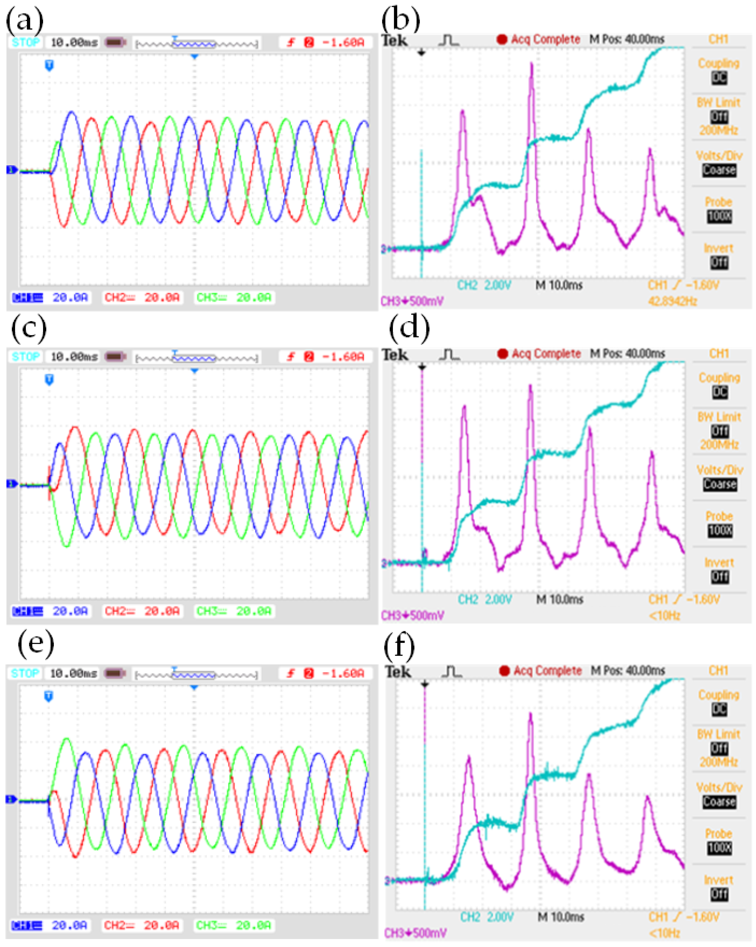
4. Experimental Research

In order to confirm the effectiveness of the tested method of starting the drive system with an induction motor with the use of vacuum circuit breakers, experimental tests were also carried out. The diagram of the electromechanical system with an induction motor with vacuum circuit breakers is shown in Figure 15. The electric motor is coupled to the braking torque through a mechanical clutch with a torque and rotational speed meter.
From among the vacuum circuit breakers available on the market, the circuit breaker from Tavrida Electric was selected for testing due to the method of synchronization of three drives located in the switching unit. It is carried out mainly in two ways [19]:
  • electrically—the same opening (closing) current impulse coming from the capacitors in the control unit is supplied to all the solenoid drive coils;
  • mechanically—the armature of each electromagnetic drive is mechanically connected to the synchronizing shaft running through the entire space of the drive chamber.
VCB vacuum circuit breakers by Tavrida Electric, type ISM/TEL-12-20, and CM/TEL-100/220-12-01A control units were used in the experimental tests.
As a result, when the circuit breaker is closed, the time of diversity between the poles is less than 1 ms. The research on this switch also shows that the time of this electrical apparatus is approximately constant. The average activation time (from the application of the switching signal to the closing of the circuit breaker contacts) is 38 ms. This is the time that should be taken into account when creating the control system. Figure 16 shows the algorithm implemented in the control system. The switching point may be at any t ON time. The system waits for the detection of the zero point of voltage in phase A (time t 0 ). During this time, the time counter is started and the control system takes into account the closing time of the vacuum circuit breakers t delayS 1 and t delayS 1 . The voltage supplying the solenoid driving coil of the vacuum circuit-breaker S1 is given at time t 1 , but the contacts of this circuit breaker will be closed at time t S 1 . The voltage supplying the solenoid driving coil of the vacuum circuit-breaker S2 is given at time t 2 , but the contacts of this circuit breaker will be closed at time t S 2 . Figure 17 and Figure 18 show a laboratory stand on which experimental tests were carried out, showing the practical application of the starting method that allows to minimize the oscillation of the electromagnetic torque of the electromechanical system.
Figure 19 and Figure 20 show the results of laboratory tests with an induction motor of the type MS 100L1-4, the nominal parameters of which are given in Table A2 (Appendix B). The experimental tests were carried out when the tested machine was loaded with a resistive torque of a constant value equal to 4 Nm. The transient waveforms during the classic (uncontrolled) starting of an induction motor are shown in Figure 19. The transient mileage during starting with the proposed procedure is shown in Figure 20. The currents in the stator windings are shown in Figure 19a,c,e and Figure 20a,c,d,f, while the rotor speed of the motor and the torque on the shaft are shown in Figure 19b,d,f and Figure 20b,d.
Figure 19 shows that during the classic starting of an electromechanical system, electromagnetic torque oscillations, including negative values, cause braking and vibration of the system. In these figures, it can also be noticed that the negative values of the electromagnetic torque appear regardless of the moment of switching on the three supply voltages. These phenomena with frequent starts of the electric machine can cause faster wear of the mechanical parts. Such a method of starting can be found in industry, especially in electric drives with 6 kV induction motors. Afterwards, DOL starting was performed again, but with a delay of switching on one phase of the supply voltage by 5 ms using the vacuum circuit-breakers. Figure 20b,e show that in the torque there are no negative torques responsible for the braking of the rotor. Figure 20c,f show that at the moment of zero detection in phase A, the switch contacts were closed and the missing phase supplying the motor was turned on with a delay of 5 ms. Laboratory tests of the induction motor starting system with the use of vacuum circuit breakers by Tavrida Electric confirm the feasibility of the proposed procedure in practice.

5. Conclusions

This article presents the method of DOL starting of drive systems with 6 kV induction motors with the use of vacuum circuit breakers and the delay of switching on one of the three phases of the supply voltage by 5 ms. This approach makes it possible to extend the operation of the drive system, especially when there are frequent starts. The computer simulation confirmed that the delay in one of the three phases of the voltage supplying the motor does not cause large oscillations of the electromagnetic torque, including negative torques, which are largely responsible for the braking and vibrations of the system. The advantage of such a starting method is also the reduction in thermal effects, as the starting time for the tested motor, regardless of the braking torque, decreases by about 1.2 s. The starting time was shortened by reducing/eliminating the inrush currents during the starting (reducing the in-rush transient component). Experimental studies of the induction motor starting system with the use of vacuum circuit breakers by Tavrida Electric have shown that it is possible to reduce the oscillation of the torque and vibrations of the system and show the simplicity of the proposed solution.

Author Contributions

Conceptualization, Z.L. and Z.K.; methodology, Z.K.; software, M.F.; validation, Z.K. and Z.L.; formal analysis, Z.K.; investigation, Z.K. and M.F.; resources, Z.K.; data curation, Z.K.; writing—original draft preparation, Z.K.; writing—review and editing, M.F.; supervision, Z.L. All authors have read and agreed to the published version of the manuscript.

Funding

This research received no external funding.

Institutional Review Board Statement

Not applicable.

Informed Consent Statement

Not applicable.

Data Availability Statement

Not applicable.

Conflicts of Interest

The authors declare no conflict of interest.

Abbreviations

The following abbreviations are used in this manuscript:
DOL startingdirect on line starting

Appendix A

Table A1. Parameters of the type SF400X6 squirrel cage induction motor.
Nominal DataParameters of Equivalent Circuits
Rated power400 kWStator resistance0.362 Ω
Voltage6000 V (Y)Rotor resistance (1)0.3645 Ω
Frequency50 HzMutual inductance0.06 H
Speed rated990 rpmStator inductance0.0631 H
Stator current48.4 ARotor inductance (1)0.0631 H
Power factor0.84L
Inertia Moment21.8 kg·m2
Efficiency94.4%
(1) Values converted to the stator side.

Appendix B

Table A2. Parameters of the MS 100L1-4 type induction motor.
Nominal Data
Rated power2.2 kWRated voltagee400 V
Speed rated1420 rpmFrequency50 Hz
Stator current4.2 APower factor0.81L

References

  1. Ludwikowski, Z.; Cieślik, S. Limitation of mechanical vibration during start-up of induction squirrel-cage motors. In Proceedings of the Problems of Automated Electrodrives—Theory and Practice, Charkov, Ukraine, 15–20 September 2003; pp. 189–190. [Google Scholar]
  2. Ludwikowski, Z.; Cieślik, S. Mathematical modeling of an electric drive with a direct starting induction motor in computer optimization of electromagnetic torque oscillation. In Materiały VIII Konferencji Naukowo-Technicznej pod Patronatem Sekcji Teorii Elektrotechniki Komitetu Elektrotechniki PAN: Zastosowania Komputerów w Elektrotechnice; Institute of Industrial Electrical Engineering, Poznan University of Technology: Poznan, Polnad, 2003; pp. 517–520. (In Polish) [Google Scholar]
  3. Akbaba, M. A novel simple method for elimination of DOL starting transient torque pulsations of three-phase induction motors. Eng. Sci. Technol. Int. J. 2021, 24, 145–157. [Google Scholar] [CrossRef]
  4. Nithin, K.S.; Jos, B.M.; Rafeek, M. An Improved Method for Starting of Induction Motor with Reduced Transient Torque Pulsations. Int. J. Adv. Res. Electr. Electron. Instrum. Eng. 2013, 2, 1–9. [Google Scholar]
  5. Cieślik, S.; Ludwikowski, Z. Start-Up of Induction Motor with Limitation of Starting Electromagnetic Torque Oscillation—Laboratory Research; National Technical University of Kharkiv: Dnieprodierzynsk, Ukraine, 2007; pp. 58–59. [Google Scholar]
  6. Zenginobuz, G.; Cadirci, I.; Ermis, M.; Barlak, C. Performance Optimization of Induction Motors during Voltage-Controlled Soft Starting. IEEE Trans. Energy Convers. 2004, 19, 278–288. [Google Scholar] [CrossRef]
  7. Shabestari, P.M.; Mehrizi-Sani, A. Current Limiting and Torque Pulsation Reduction of the Induction Motors. In Proceedings of the 2019 IEEE Power & Energy Society General Meeting (PESGM), Atlanta, GA, USA, 4–8 August 2019. [Google Scholar]
  8. Cieslik, S.; Ludwikowski, Z. Oscillation Limitation of Electromagnetic Torque of Squirrel-Cage Motor on Starting. Computer Applications in Electrical Engineering; Institute of Industrial Electrical Engineering, Poznan University of Technology: Poznan, Polnad, 2004. [Google Scholar]
  9. Cieślik, S. Mathematical Modeling and Simulation of Electric Power Systems with Induction Generators; Wydawnictwo Uczelniane Uniwersytetu Technologiczno-Przyrodniczego w Bydgoszczy: Bydgoszcz, Poland, 2008. (In Polish) [Google Scholar]
  10. Ludwikowski, Z.; Cieslik, S.; Plakhtyna, O. Dynamic properties of the electric drive with an induction motor using start-up with limited oscillation of the electromagnetic torque. In Techniczna Elektrodinamika; Ukrainian National Academy of Sciences: Kijów, Ukraine, 2004; pp. 38–40. [Google Scholar]
  11. Ludwikowski, Z.; Cieslik, S.; Plakhtyna, O. The analysis a lag of induction motor’s one phase connecting influence on the electromagnetic torque oscillation under starting. In Tieoretyczna Elektrotechnika; Ukrainian National Academy of Sciences: Lwów, Ukraine, 2004; pp. 61–69. [Google Scholar]
  12. Kłosowski, Z.; Cieślik, S. The Use of a Real-Time Simulator for Analysis of Power Grid Operation States with a Wind Turbine. Energies 2021, 14, 2327. [Google Scholar] [CrossRef]
  13. Kłosowski, Z.; Cieślik, S. Real-Time Simulation of Power Conversion in Doubly Fed Induction Machine. Energies 2020, 13, 673. [Google Scholar] [CrossRef] [Green Version]
  14. Cieślik, S. Mathematical Modeling of the Dynamics of Linear Electrical Systems with Parallel Calculations. Energies 2020, 14, 2930. [Google Scholar] [CrossRef]
  15. Kutsyk, A.; Semeniuk, M.; Korkosz, M.; Podskarbi, G. Diagnosis of the Static Excitation Systems of Synchronous Generators with the Use of Hardware-in-the-Loop Technologies. Energies 2021, 14, 6937. [Google Scholar] [CrossRef]
  16. Kłosowski, Z.; Plakhtyna, O.; Grugel, P. Applying the method of average voltage on the integration step length for the analysis of electrical circuits. Zesz. Nauk.—Elektrotechnika 2014, 17, 17–31. [Google Scholar]
  17. Płachtyna, O.; Kłosowski, Z.; Żarnowski, R. Mathematical model of DC drive based on a step-averaged voltage numerical method. Przegląd Elektrotechniczny 2011, 87, 51–56. (In Polish) [Google Scholar]
  18. Plakhtyna, O.; Kutsyk, A.; Semeniuk, M. Real-Time Models of Electromechanical Power Systems, Based on the Method of Average Voltages in Integration Step and Their Computer Application. Energies 2020, 13, 2263. [Google Scholar] [CrossRef]
  19. Travida Electric. VACUUM CIRCUIT BREAKERS 15.5—27 KV—Technical Manuals. Available online: https://www.tavrida.com/upload/iblock/747/TES_CBdoc_UG_VCB_1(EN)_1.7.pdf (accessed on 6 June 2022).
Figure 1. Waveform of electromagnetic torque and rotor speed (a), as well as mechanical dynamic characteristics (b) of a squirrel-cage induction motor during the classic direct starting.
Energies 15 04246 g001
Figure 2. Waveform of electromagnetic torque and rotor speed (a), as well as mechanical dynamic characteristics (b) of a squirrel-cage induction motor during the direct starting proposed in this article.
Energies 15 04246 g002
Figure 3. The idea of limiting the oscillation of the electromagnetic torque during the starting of the drive system with an induction motor.
Energies 15 04246 g003
Figure 4. Hodograph of the magnetic flux in the d-q orthogonal system, where: (a) for the direct start-up; (b) for the new direct start-up, with a voltage delay of one phase voltage equal to 5 ms; (c) for the new direct start-up, with a voltage phase switching delay of 25 ms.
Energies 15 04246 g004
Figure 5. Schematic diagram of the analyzed electromechanical system.
Energies 15 04246 g005
Figure 6. Substitute diagram of the analyzed electromechanical system with division into structural elements.
Energies 15 04246 g006
Figure 7. Waveforms of physical quantities for direct starting, with no voltage phase delay and load moment T o = 0 Nm: (a) time waveforms of the stator currents in three phases and rotational speed; (b) time waveform of the electromagnetic torque and rotational speed; (c) hodograph of the stator fluxes; (d) segment of the time waveform of the electromagnetic torque and rotational speed, in the first moment of start-up.
Energies 15 04246 g007
Figure 8. Waveforms of physical quantities for direct starting, with the voltage phase switching on delay of t delay = 5 ms and load torque T o = 0 Nm: (a) time waveforms of the stator currents in three phases and rotational speed; (b) time waveforms of the electromagnetic torque and rotational speed; (c) hodograph of stator fluxes; (d) fragment of the time waveforms of the electromagnetic torque and rotational speed, in the first moment of starting.
Energies 15 04246 g008
Figure 9. Waveforms of physical quantities for direct start-up, with no voltage phase delay and constant load torque T o = 500 Nm: (a) time waveforms of the stator currents in three phases and rotational speed; (b) time waveform of the electromagnetic torque and rotational speed; (c) hodograph of stator fluxes; (d) segment of the time waveform of the electromagnetic torque and rotational speed at the first moment of starting.
Energies 15 04246 g009
Figure 10. Waveforms of physical quantities for direct start-up, with a delay of switching on the voltage phase of t delay = 5 ms and constant load momentum T o = 500 Nm: (a) time waveforms of the stator currents in three phases and rotational speed; (b) time waveform of the electromagnetic torque and rotational speed; (c) hodograph of stator fluxes, (d) segment of the time waveform of the electromagnetic torque and rotational speed, in the first moment of starting.
Energies 15 04246 g010
Figure 11. Waveforms of physical quantities for direct starting, with no voltage phase delay and fan load moment T o = 3859 n 990 2 : (a) time waveforms of stator current in three phases and rotational speed; (b) electromagnetic torque and rotational speed timing; (c) hodograph of stator fluxes; (d) electromagnetic torque and rotational speed timing diagram, in the first moment of starting.
Energies 15 04246 g011
Figure 12. Waveforms of physical quantities for direct starting, with a voltage phase switching delay of t delay = 5 ms and a fan load moment T o = 3859 n 990 2 : (a) time waveforms of stator currents in three phases and rotational speed; (b) time course of electromagnetic torque and speed rotational speed; (c) hodograph of stator fluxes; (d) fragment of the electromagnetic torque and rotational speed temporal waveform, in the first moment of starting.
Energies 15 04246 g012
Figure 13. Waveforms of physical quantities for direct starting, with no voltage phase delay and fan load torque T o = 59 + 3800 n 990 2 : (a) time waveforms of the stator currents in three phases and rotational speed; (b) time waveforms of the electromagnetic torque and rotational speed; (c) hodograph of stator fluxes; (d) fragment of the time waveform of the electromagnetic torque and rotational speed in the first moment of starting.
Energies 15 04246 g013
Figure 14. Waveforms of physical quantities for direct starting, with a voltage phase switching delay of t delay = 5 ms and a fan load moment T o = 59 + 3800 n 990 2 : (a) stator currents in three phases and rotational speed; (b) electromagnetic torque waveform and rotational speed; (c) hodograph of stator fluxes; (d) fragment of the time waveform of electromagnetic torque and rotational speed, in the first moment of starting.
Energies 15 04246 g014
Figure 15. Detailed schematic diagram of the analyzed electromechanical system with cage induction motor.
Energies 15 04246 g015
Figure 16. Algorithm for switching on an induction motor by vacuum circuit breakers.
Energies 15 04246 g016
Figure 17. The electromechanical system on which the DOL starting with delay of phase voltage switching was tested.
Energies 15 04246 g017
Figure 18. Control system for switching on an induction motor with vacuum circuit breakers.
Energies 15 04246 g018
Figure 19. Waveforms of physical quantities during the classic direct starting of an electromechanical system with the use of a vacuum circuit breaker, where: (a,c,e) concerns the stator winding currents ( i A —CH1, i B —CH2, i C —CH3: scale 20 A/div), (b,d,f) concerns the torque on the shaft ( T —CH3: scale 50 Nm/1V) and the rotor speed of the motor ( n —CH2: scale 15 rpm/1V).
Energies 15 04246 g019
Figure 20. Waveforms of physical quantities during the direct start-up of the electromechanical system by means of a vacuum circuit breaker with a delay of switching on the phase supplying the motor by 5 ms, where: (a,c,d,f) concerns the stator winding currents ( i A —CH1, i B —CH2, i C —CH3: scale 20 A/div), (b,e) concerns the torque on the shaft ( T —CH3: scale 50 Nm/1V) and the rotor speed of the motor ( n —CH2: scale 15 rpm/1V).
Energies 15 04246 g020
Publisher’s Note: MDPI stays neutral with regard to jurisdictional claims in published maps and institutional affiliations.

