1. Introduction
When it is difficult to connect directly to a large system, such as on an island or in a mountainous area, an MG that supplies electricity with a diesel generator is built to supply electricity. In Korea, diesel generators supply electricity to 57 islands managed by KEPCO (Korea Electric Power Corporation) and some islands managed by local governments. In some cases, one diesel generator is used on islands managed by local governments, but at least three diesel generators are installed on islands managed by KEPCO and two or more diesel generators operate simultaneously. According to data from KEPCO, 57 islands managed by KEPCO consumed 77,710 kiloliters of diesel for power generation in 2019, while 73,489 kiloliters were consumed in 2020 when the number of tourists decreased due to the COVID-19 pandemic [
1]. In order to reduce the use of fossil fuels, Korea has made several attempts to supply electricity to the MG using renewable energy and ESS since 2012. On Gasa island, in one of several trials, diesel consumption decreased by about 75% compared to before the installation of renewable energy and ESSs [
2]. However, most attempts to replace diesel generators with renewable energy and ESSs in Korea have been unsuccessful. There is one ESS used for charging or discharging, and, for economic reasons, a diesel generator plays an important role [
3].
When one ESS operates at a constant frequency, it has the advantage that the frequency of the MG remains constant at the nominal frequency. However, if renewable energy and load are distributed over a wide area, the voltage of each part of the MG will fluctuate according to the amount of renewable energy generation and load even if the ESS regulates the voltage as constant at the connection point. Moreover, if a failure occurs in the ESS, a power outage occurs in the MG, which reduces the reliability of the power supply. Considering an increase in power demand over a long period of time, the initial investment cost is excessive, because it is necessary to install an ESS with an excessively larger capacity than the full load from the beginning. In addition, since the ESS cannot be operated at the optimal operating point, the efficiency of the entire MG is also lowered.
Considering the stability and scalability of the MG, multiple ESSs whose unit capacity is smaller than the maximum power demand of the MG must be installed and operated in parallel. In order to maximize the efficiency of the entire MG, it is necessary to determine the operation and stop of each ESS, as well as the operational reference value. When it is necessary to expand the ESS according to the increase in power demand, it is possible to easily respond to the increase in power demand by adding an ESS with a capacity corresponding to the increased power demand. Finally, the frequency must be stable even if some of the operating ESSs fail.
The ESS supplies power to the grid or absorbs power from the grid through a power converter. Various control methods have been proposed to share power among multiple power converters [
4,
5,
6,
7,
8,
9,
10,
11,
12,
13,
14,
15,
16]. Most of the research has aimed at equally distributing power between power converters operating in parallel, and some studies have considered dropouts of power converters operating in parallel or sudden changes in load. The method for operating multiple power converters in parallel can be broadly divided into the master–slave control method and the droop control method.
In the master–slave control method, one set of generators, designated as master devices, outputs a constant frequency voltage [
5]. Other devices are designated as slave devices and operate in synchronization, with the voltage and frequency generated by the master device. Slave devices control active and reactive power according to commands from the central controller [
5,
6,
8]. Basically, the master–slave control method requires a high-speed communication scheme, but a control method using a low-speed communication scheme has also been studied. The master device receives the maximum and minimum power data that can be generated from the distributed generators and transmits the transmission factor to all the slave devices to control the voltage of the microgrid so that it does not exceed the allowable range [
9]. In addition, the microgrid is divided into a DC part and an AC part, and using wireless communication, the information from devices located in each part is collected, and the amount of power generated is controlled to control the power flowing from utility to ‘0’ [
10]. Since the master device retains a constant frequency, the frequency supplied to the load has the advantage of being constant. However, if the load fluctuation range is large or other power generation devices are separated due to failure, etc., the master device bears the increased or decreased active power and reactive power. In this process, the master device becomes overloaded, and the master device controller determines that it is an overload failure and can disconnect itself from the grid. In order to prevent the master device from being disconnected due to an overload fault, either the master device is designed to exceed the actual required capacity, or the central controller must command a new power reference value to the slave devices within several milliseconds to several tens of milliseconds. In the laboratory, it is possible to command the power reference value at a high speed, but in an island MG environment, where various distributed power sources are distributed in a wide area, it is impossible to command the power reference value at a high communication speed.
In the droop control method, all controllable devices contribute to maintaining the frequency [
5,
6,
7,
11]. The generating devices operate according to each power reference value, and when the frequency or voltage deviates from the set value, they increase or decrease the active power or reactive power in proportion to the difference from the set value [
5,
6,
7,
11,
12]. Since all devices contribute to maintaining the frequency, there is an advantage that all devices share the transient state, even if the load changes rapidly or the power of the generator changes rapidly. However, if fewer than four or five devices operate with droop control, there are the following problems. In the case where the droop compensation is set to operate slowly, if a failure occurs in one ESS in operation, before the frequency is restored to normal, the normal ESS may be separated from the grid as a low-frequency or high-frequency failure. Conversely, when droop compensation is set to act quickly, it can react sensitively to small power changes in the load or other generators, resulting in continuous ripples in frequency or voltage [
12]. A typical droop control method does not require a central controller. However, it is necessary to use an MG central controller to keep the frequency and voltage constant in a situation where the load constantly fluctuates. One case demonstrated the effect of the communication speed between the central controller and the distributed power source [
13]. When the central controller collected information on each part of the MG at a 1 ms cycle, the voltage and frequency recovered quickly and smoothly, but when the information collection cycle increased to 500 ms and 1 s, it took several seconds or more to follow the frequency. In an actual MG, information is collected every several hundred milliseconds or longer, so if an ESS fails in a parallel situation, before the frequency is restored to normal, ESSs in normal operation may also be separated from the MGs due to frequency failure. Other studies have shown that it took more than a second to stabilize to the newly formed reactive power sharing point when the load changed rapidly [
12]. There was also a study considering the separation of the power converter in parallel operation from the MG [
16]. The harmonic filter parameter of the power converter used in the simulation of this study was 6 to 10 times larger than that of the actual power converter. If the harmonic filter parameter was too large compared to the actual one, the voltage and current did not fluctuate rapidly in the transient state. That is, the current of the power converter in operation changed slowly and returned to its normal state before detecting a fault. However, because the parameters were abnormally large, if implemented in practice, the product price would also be abnormally high.
Previous research has used very fast communication with a communication cycle of several milliseconds or less or evenly distributed power between power converters. However, the ESS installed in the MG must be charged or discharged with different reference values according to the situation of each device, and it is difficult to keep the communication cycle as short as several milliseconds, because the distance between each ESS can be several kilometers.
To ensure the reliability to stably maintain an MG and the scalability according to the increase in power demand, this paper proposes a new control that combines the advantages of the master–slave control method and the droop control method. The new control allows the frequency of the MG to be varied within the allowable range depending on the situation, and droop control is applied to the slave device. Moreover, when the master device is disconnected from the MG, the slave device changes to the master device to keep the frequency constant. When the proposed control is applied, each ESS actively responds to changes in voltage and frequency even if there is a large deviation in power supply and demand in the MG and quickly switches to a stable state after a short transient state. To verify the proposed control method, a simulation model based on an actual ESS was developed, and simulations were performed under various conditions.
This paper is organized as follows.
Section 2 summarizes the microgrid configuration and traditional control methods.
Section 3 describes the proposed control method. In
Section 4, the simulation model to validate the proposed control method is arranged.
Section 5 compares the proposed control method with the traditional control method. Finally,
Section 6 concludes the paper.
2. Conventional MG Control
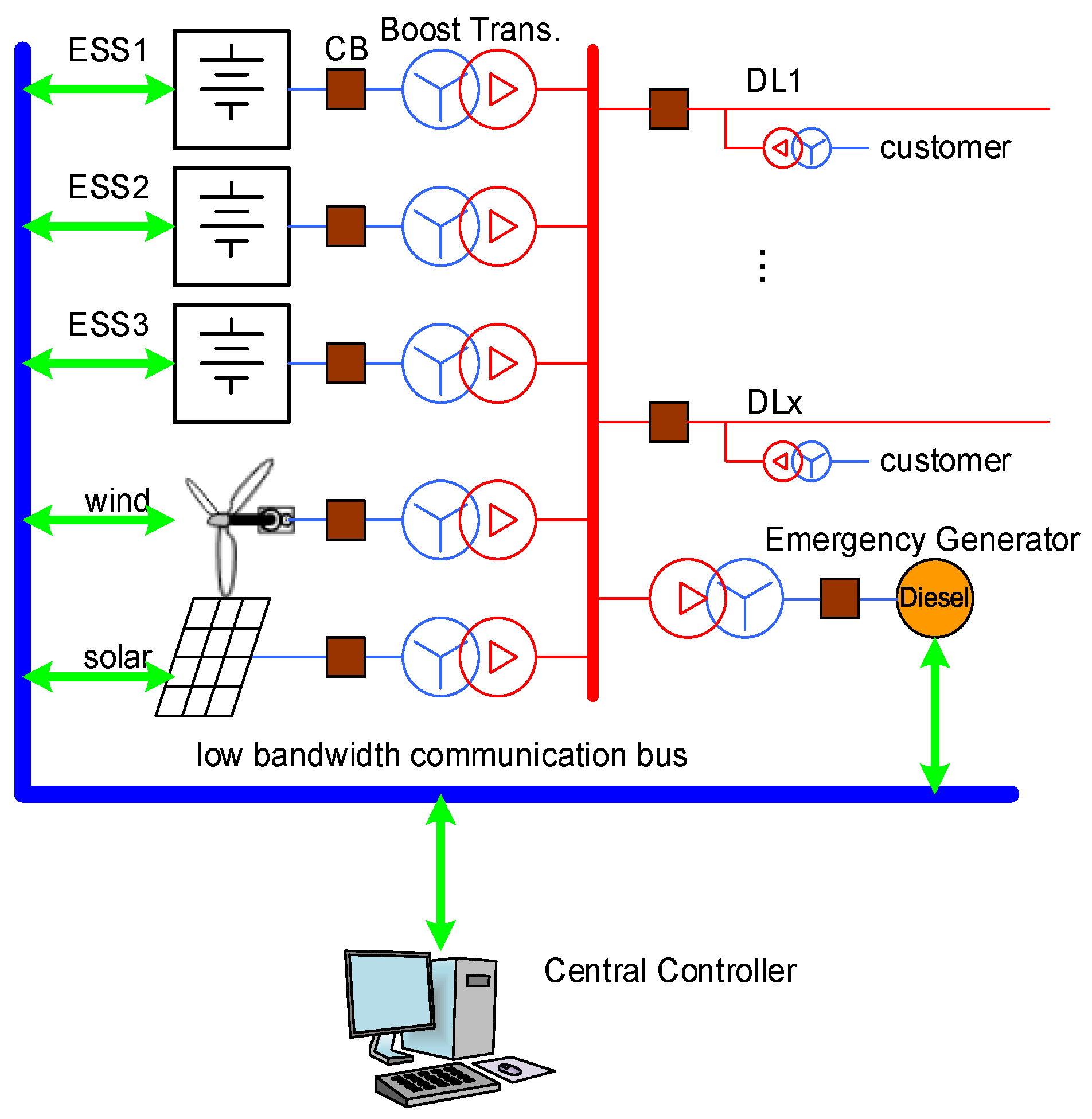
An MG based on renewable energy and ESS should be configured as shown in
Figure 1. The MG central controller communicates with individual distributed power supplies at intervals of hundreds of milliseconds to several seconds to command an operating reference or output limit and collects the operating information of the MG. Multiple ESSs are used, and electricity is supplied from renewable energies such as wind power and solar power. Each ESS performs output control according to the instructions of the MG central controller. Solar power generation and wind power generation using a power converter can limit the power generation through communication from the MG central controller. Diesel generators operate when renewable energy generation is insufficient or when there is a serious problem with the ESS.
Various droop control methods and master–slave control methods have been developed to keep the frequency constant in the MG composed of various power devices. This section briefly summarizes the representative methods.
2.1. Droop Control Method
In order to keep the voltage and frequency constant in the large-scale grid, a large-scale generator, such as thermal power or nuclear power, operates with constant power reference from a central controller. It also controls the voltage at the point where the generator is connected. Basically, the frequency of the grid remains constant around the nominal frequency. However, if the demand for power exceeds the supply due to sudden load fluctuations or some generators drop out from the grid, the frequency of the grid gradually decreases. When the frequency that was kept constant decreases, the rotational speed of the generator decreases in proportion to the frequency. At this time, some of the rotational energy of the rotor is converted into electrical energy and supplied to the grid, and the frequency drop is slowed. In this situation, the controller that manages the entire power grid keeps the frequency constant around the nominal frequency by instructing the generators to respond to the demand with a new active power reference value. Conversely, when the frequency is higher than the nominal frequency, a part of the energy supplied to the grid is used to increase the rotation speed of the generator, and the active power supplied to the grid is reduced, so that the frequency increases slowly. The larger the inertia of the generator, the more active power is supplied or absorbed according to the frequency change.
The droop control method works similarly to the generator control of the large grid in the MG. Each generating device is controlled by the active power reference setting. Similar to how the rotor inertia of a large generator slows down the frequency change, when the frequency of the MG deviates from the set value, it increases or decreases the active power of the generating device in proportion to the frequency change [
11,
13,
14,
15].
To summarize from the point of active power,
, the sum of the active power of all distributed power sources connected to the grid, is the same as
, the sum of the loss in the grid line, and
, the active power consumed by the total load.
The active power of each distributed power supply can be set to
or set to a different value according to the rated capacity and situation of each power source. In addition, if the frequency measured by each power source is outside the allowable range, the active power compensation value is calculated in proportion to the frequency deviation.
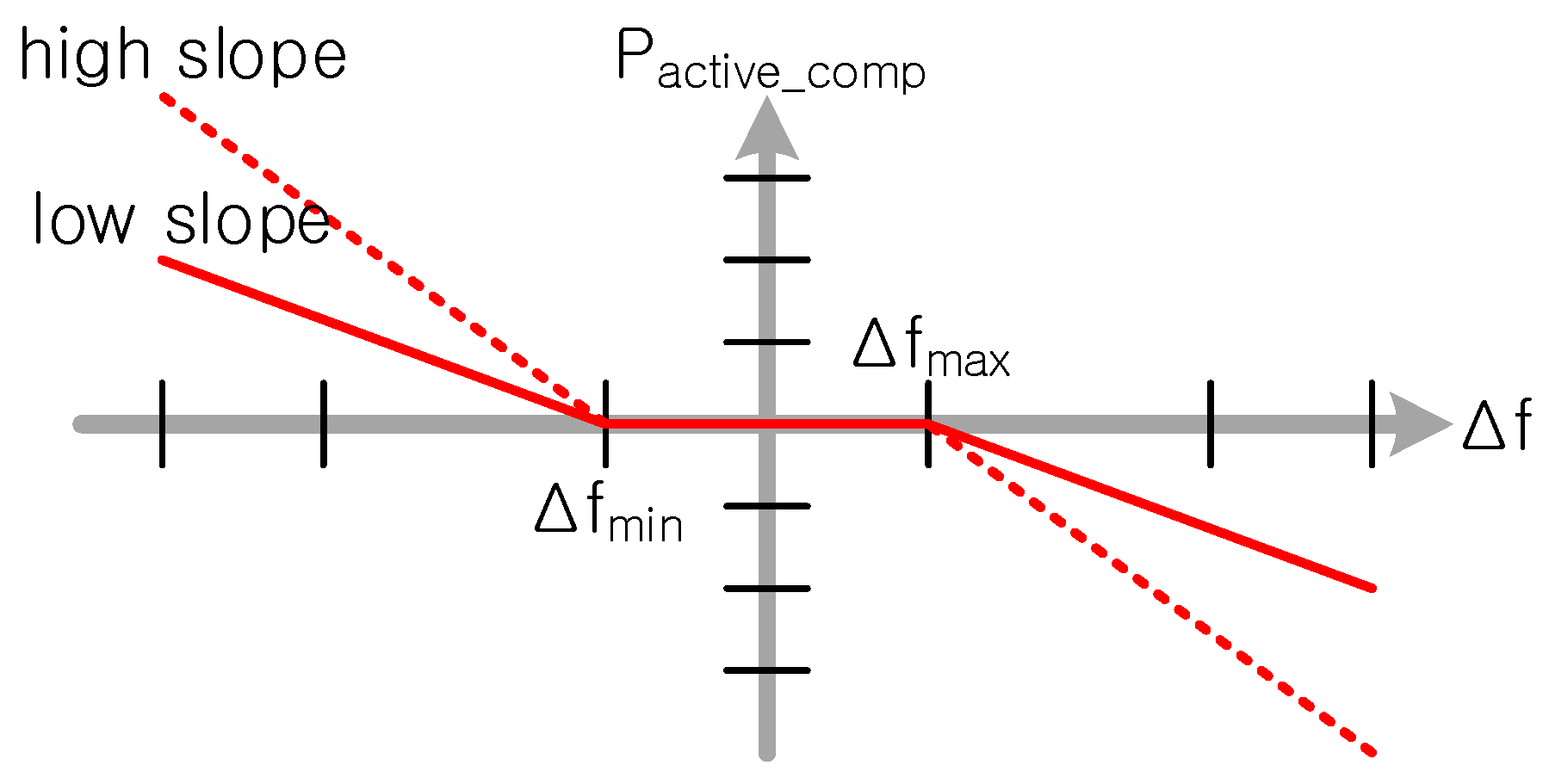
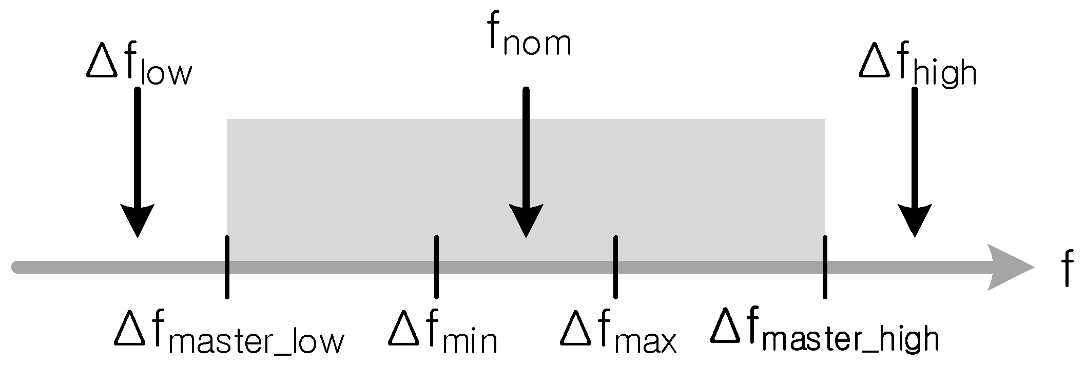
Figure 2 shows the concept of frequency-active power droop. The frequency tolerance for droop can be divided into
when the frequency is high and
when the frequency is low, and the tolerance can be set to ‘0’. If it is outside the allowable range, the compensation value is calculated in proportion to the deviation. The proportional factor can be set differently for each power source. When the frequency is lowered, more active power is supplied to the grid than the set value or less active power is supplied from the grid.
If the allowable frequency range is set to ‘0’, the active power reference
of the n-th power source is calculated as follows:
where
is the active power setpoint of the n-th power source,
is the frequency-active power droop coefficient,
is the measured frequency,
is the nominal frequency, and
is the nominal active power of the n-th power source.
Similar to the frequency-active power droop, there is also a voltage-reactive power droop. The voltage reference value is set for each power source, and the reactive power compensation value is calculated when the measured voltage deviates from the voltage reference value [
14].
When the droop control method is applied, all distributed generation devices participate to balance the supply and demand of active and reactive power in the grid, so that the load is not concentrated on a specific device in a transient state. Moreover, since no communication is required, it is advantageous to extend the MG to geographically distant places.
However, in the case of fewer devices participating in grid forming, if one of the participating devices is disconnected from the MG, the frequency or voltage will be outside the allowable range, which may lead to a power outage of the entire MG. To enable the droop control to respond quickly to events outside the device, a large droop coefficient can be set. However, if the droop coefficient is too large, it responds sensitively to small changes in power generation or load, resulting in continuous ripples in frequency or voltage.
Droop control does not require a central controller, but in some cases, such as MGs on islands, a central controller is used to change the set value of active power and reactive power and drop coefficient, depending on the situation [
5,
13].
Various modifications have been proposed to improve the shortcomings of such droop control [
5,
6].
2.2. Master–Slave Control Method
In the case of an independent operation method in which one device supplies all electricity, one device controls the voltage and frequency at a constant value, and the load operates according to the voltage and frequency generated by the power device. A variable voltage fixed frequency method is also possible, which constantly controls the terminal voltage that fluctuates according to the size of the load. In the case of an MG consisting of a small number of generating devices, there is also a method in which one device synthesizes a voltage of a constant frequency, similar to an independent operation. Other devices share the voltage control by controlling the active and reactive power in synchronization with the frequency generated by one device [
8]. This method is master–slave control. The master device operates at a constant frequency, and the slave devices operate with active/reactive power control.
In the case of the master–slave method, a central controller is required, and the slave devices receive the active power set value
and reactive power set value
from the central controller. The active power of the master device,
, is determined as follows:
where
is the total active power of the slave devices.
Since the active power of the master device is determined according to the demand and supply of active power in the grid, the active power of the master device continuously fluctuates according to the active power fluctuation of other distributed power devices or load fluctuations.
Similar to active power, the reactive power of the master device is also determined by supply and demand in the grid. If the output voltage of the master device is changed to keep the grid voltage constant, the reactive power of the master device is also changed.
In the master–slave control method, the central controller consists of a simple algorithm because the master device balances the supply and demand of active and reactive power. In addition, there is an advantage in that the master device maintains a constant frequency even if the amount of power generation or load changes.
However, the master unit must withstand a transient state until the central controller instructs a new reference value to the slave devices [
5]. In the worst case, power greater than nominal power may be applied to the master device. This is a disadvantage of the master–slave method. In addition, when the power generation or load changes rapidly, a fast communication system is required to instruct the reference value to the slave device; thus, if each device is distributed over a long distance, the system cost increases and the scalability decreases.
Various modifications have been proposed to improve the shortcomings of the master–slave control method [
5,
6].
3. Proposal for an MG Control Method
The advantages and disadvantages of droop control and master–slave control, summarized above, are as follows. Droop control does not concentrate the burden on one generating device even in a transient state, but there is a problem in that the frequency continuously fluctuates when the amount of power generation or the fluctuation range of the load is large. Conversely, the master–slave method can keep the frequency constant, but, in a transient state, an overload can be applied to the master device, and a fast communication system is required.
By combining the advantages of droop control and master–slave control, this paper proposes a control method to stably maintain the frequency of an MG even if some of the ESSs in operation fail in an MG composed of renewable energy sources and a small number of ESSs.
The proposed method is as follows: (1) It operates as a master–slave control method. (2) In order to prevent overload in the master device, the proposed method changes the frequency of the MG within the allowable range when an overload is applied to the master device and applies frequency-active power droop to the slave device. (3) If the master device is disconnected from the MG, the proposed method changes the higher priority slave device to the master device. (4) The proposed method only applies to ESSs but not to wind power or solar power. Except when the ESS can no longer be charged, wind or solar power runs with maximum power point tracking control.
3.1. Configuration of Control System
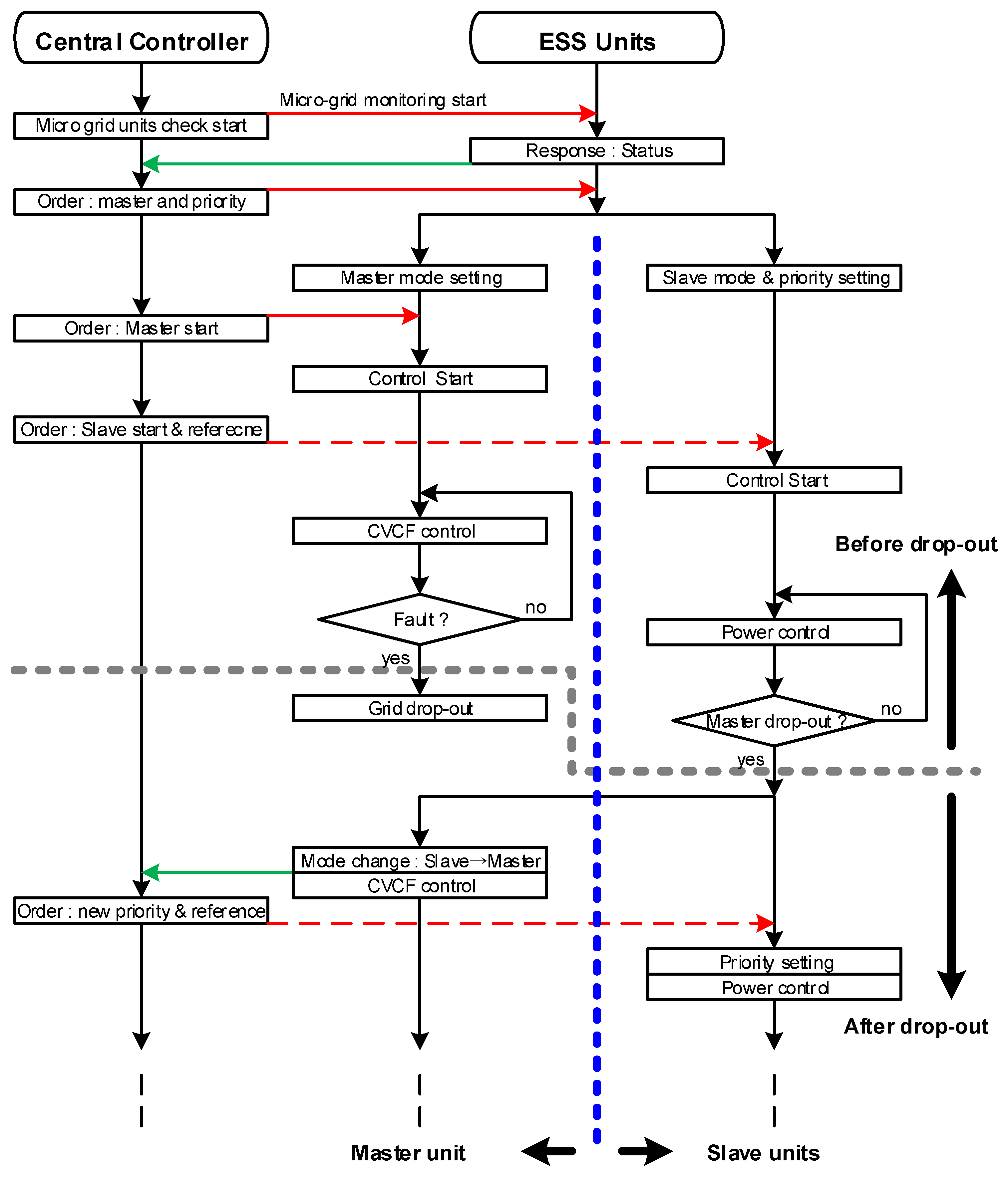
The MG control system proposed in this paper consisted of a central controller and an ESS controller. The overall operation sequence is shown in
Figure 3.
The central controller is similar to the general master–slave controller, and the function of determining the priority between slave devices and changing the higher priority slave device to the master device when the master device has difficulty operating normally has been added. When the master device is disconnected from the grid, the frequency of the MG may be outside the allowable range or stabilized at a new frequency close to the nominal frequency depending on the ratio of active power borne by the master device and the setting of the droop coefficient. If the frequency is outside the allowable range, the slave device with a higher priority changes itself to the master device. However, if a stable state is maintained at a frequency close to the nominal frequency, the central controller instructs the higher priority slave device to change to the master device and gives other slave devices a new priority. The central controller may limit the maximum output of distributed generation devices other than ESSs.
As shown in
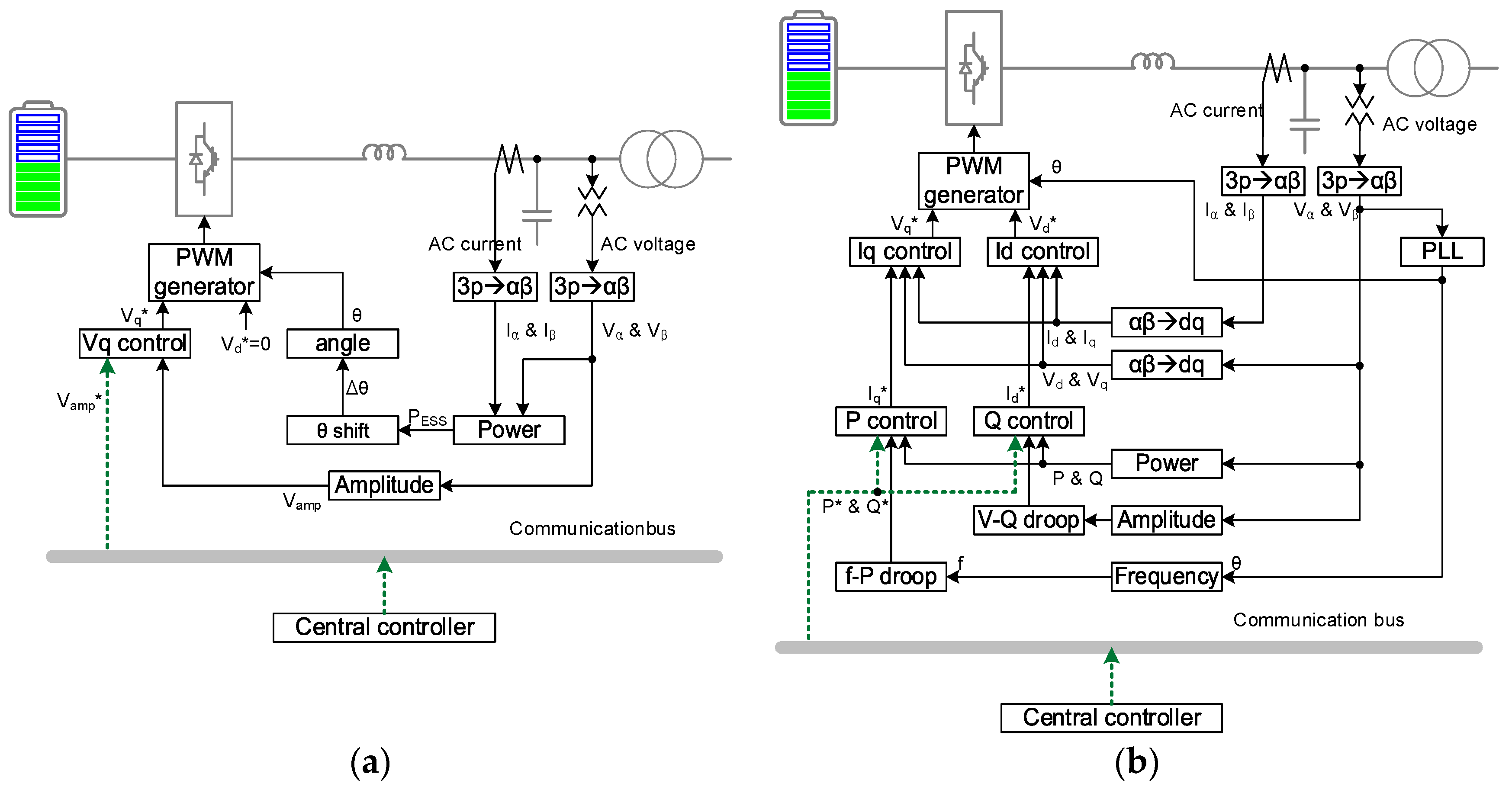
Figure 4, the ESS controller consists of a master device mode and a slave device mode. The ESS controller operates in master device mode or slave device mode, according to the command of the central controller, and when the master device is disconnected from the grid, the higher priority slave device controller decides to change to the master mode. The operation mode of the ESS controller is described in detail below.
3.2. Master Mode Controller
The master mode controller was configured as shown in
Figure 4a and controls the output voltage magnitude and frequency of the ESS. Three-phase voltage and three-phase current were converted into stationary coordinate system variables
,
,
, and
, and active and reactive power were calculated from stationary coordinate system variables. A conventional master mode controller constantly increases the phase angle
to keep the frequency constant. However, the master mode controller proposed in this paper adds the calculation of the phase angle compensation value
from the magnitude of the active power in order to change the frequency according to the situation. Moreover, from
and
, the actual magnitude
of the voltage output by the master mode device is calculated. The actual magnitude of the calculated voltage is input to the voltage controller (Vq control). Finally, the voltage synthesized in the converter is determined by the d-axis voltage reference value
and the q-axis voltage reference value
of the synchronous coordinate system. In the master mode controller,
is fixed as ‘0’.
3.2.1. AC Voltage Control
One of the controls by the master mode controller is
, the magnitude of the AC voltage output by the master device. At the output terminal of the ESS, the magnitude reference value
of the AC voltage can be received by communication from the central controller, or a value set by the controller itself can be used. The magnitude of the AC voltage output by the master device is calculated as follows:
where
is the proportional control gain,
is the integral control gain,
is the voltage measured at the output terminal of the master device, and
is the voltage reference value of the master device. The d-axis voltage reference value
of the master device is controlled as ‘0’.
3.2.2. MG Frequency Shift in Case of Overload
In non-overload conditions, the master unit maintains the output frequency at the nominal frequency . However, in the event of a sudden change in power generation or load in master–slave control, the master device is responsible for the transient state. During the transient state, active power exceeding nominal power may be applied to the master device. If the condition of exceeding the nominal power continues, the master unit will recognize it as a failure and disconnect it from the grid.
To prevent this situation, this paper proposes a method of shifting the frequency of the MG to reduce the magnitude of the overload borne by the master device and the duration in the transient state.
In steady state, the master device controller increases the phase angle of the output voltage to a constant size, and the frequency remains constant. However, when the absolute value of the master device active power
becomes higher than the nominal power, the phase angle compensation value
is calculated as follows:
where
is the sign of the active power of the master device. When the active power is supplied from the ESS to the MG, the sign is (−); when the active power is supplied from the MG to the ESS, the sign is (+), and
is the coefficient for calculating the phase angle compensation value. In order to limit the frequency variable range, the maximum and minimum values of the phase angle compensation values, calculated as in Equation (5), are limited.
The phase angle
of the voltage output from the master device is calculated as follows:
where
is the phase angle in the previous period, and
is the amount of phase angle change during one sampling period of the master device controller. The amount of phase angle change is calculated as follows:
where
is the sampling frequency of the master device controller.
If the phase angle compensation value is ‘0′, the voltage phase angle increases by every sampling period to become a nominal frequency. If the sign of the phase angle compensation value is (+), the phase angle increases faster, and the frequency becomes higher than the nominal frequency. Conversely, if the sign of the phase angle compensation value is (−), the phase angle increases more slowly, and the frequency becomes lower than the nominal frequency.
When the master device shifts the frequency to a value different from the nominal frequency, the frequency-active power droop operates in the slave device controller, and the slave devices share the active power of the master device that exceeds the nominal power. After that, if the central controller sends a new active power reference value to the slave device by reflecting the overload of the master device, the frequency of the MG is restored to the nominal value.
3.3. Slave Mode Controller
In this paper, in order to alleviate the overload of the master device, droop control was introduced in the slave device, and when the master device was disconnected from the MG, the control of the slave device to change its mode to the master device was proposed. The proposed slave mode controller was configured as shown in
Figure 4b.
The slave mode controller controls the active power and reactive power according to the command of the central controller, and the frequency-active power droop and voltage-reactive power droop operate depending on the frequency and voltage size of the power grid to assist the active power and reactive power controller. The same as the master mode controller, three-phase voltage and three-phase current were converted into stationary coordinate system variables , , , and , and active power , reactive power , and the magnitude of the grid voltage were calculated. A phase lock loop (PLL) uses and to calculate the voltage phase angle and frequency of the PCC. and are input to f-P droop and V-Q droop, respectively, to calculate the active power compensation value and reactive power compensation value. The active power and reactive power compensation values are input to the active power controller and reactive power controller, respectively, to calculate the q-axis current reference value and the d-axis current reference value of the synchronous coordinate system. and are input to each current controller to calculate the q-axis voltage reference value and the d-axis voltage reference value of the synchronous coordinate system to be synthesized in the converter.
Moreover, although not shown in
Figure 4b, the slave mode controller checks the status of the master device through frequency. When the frequency of the MG is outside the allowable range, the slave device with a higher priority judges that the master device is disconnected from the MG and changes itself to the master device to keep the frequency constant.
3.3.1. Droop Control of Active and Reactive Power
When active power is supplied from the slave device to the grid, i.e., when the active power is supplied to the grid by discharging the battery, the sign of active power is (+). The MG central controller commands the active power reference value to each slave device in consideration of the amount of power generated by the distributed generator, the power demand of the load, and the battery charge status of the ESSs.
When the MG central controller commands the active power reference value, the slave device controller controls the active power by adding the active power reference value sent from the central controller and the droop, according to the frequency of the grid. The active power controller of the slave device controls the active power of the slave device according to the reference value
calculated as shown in the following equation:
where
is the active power reference value from the central controller,
is the frequency-active power droop coefficient, and
is the measured grid frequency. If the frequency is higher than the set range, that is, at a frequency higher than
, the slave device operates in the direction of decreasing the active power sent to the grid or increasing the active power taken from the grid. Conversely, at frequencies lower than
, it operates in the direction of increasing the active power sent to the grid or decreasing the active power taken from the grid. When the active power reference value is determined, the q-axis current reference value
is calculated.
Under normal conditions, the frequency of the grid is kept constant at the nominal frequency, because the master unit keeps the frequency constant. However, the frequency fluctuates in three cases. First, when the active power of a load or a generating unit changes rapidly, the frequency measured by the slave device is different from the nominal frequency for a short time. In this case, the frequency of the grid is restored to the nominal frequency before the controller of the slave device reacts. Second, as described in the master mode, when the master device has to bear excessive power exceeding the nominal power due to a sudden change in the active power of the generating devices or load, the master device controller operates to decrease or increase the frequency within a limited range. Third, if the master device is disconnected from the grid by accident, the frequency fluctuates.
The central controller commands the reactive power reference value to each slave device in consideration of the load and the voltage of each part. The slave device controller controls the reactive power with a reference value that is the sum of the reactive power reference value sent from the central controller and the compensation value set by the voltage-reactive power droop. The reactive power controller of the slave device controls the reactive power of the slave device according to the reference value
calculated as shown in the following equation:
where
is the reactive power reference value sent from the central controller,
is the voltage-reactive power droop coefficient,
is the nominal voltage of the grid, and
is the measured voltage amplitude. As with the frequency-active power droop, the voltage-reactive power droop operates only when the measured voltage is outside the set range. If the voltage is higher than the set value, the voltage-reactive power droop operates and moves the reactive power reference value in the inductive direction, rather than the command value of the central controller. Conversely, if the voltage is lower than the set value, the reactive power reference value is moved in the capacitive direction rather than the command value of the central controller.
3.3.2. Change Master Mode of Slave Device
Another function of the slave mode controller is to measure the frequency of the grid to confirm that the master device is operating normally. As described in the previous section, if the master unit is connected to the grid and is operating, the frequency remains within a certain range of the nominal frequency. However, when the master device is disconnected from the grid, the frequency varies depending on the situation.
If the active power borne by the master device is not large, and the droop controller of the slave device compensates sufficiently, the frequency of the grid remains within the allowable range, and the slave device may not be able to determine that the master device is separated from the grid. In this case, the central controller commands the higher priority slave device to change to the master device through communication.
If the active power borne by the master device is large or the droop controller of the slave device does not compensate sufficiently, the grid frequency is outside the allowable range. In this case, the slave device determines that the master device is disconnected from the grid, and the slave device with a higher priority decides to change to the master device by itself.
Figure 5 shows the frequency relationship in the master mode and slave mode controllers. If the master device is connected to the MG, then the measured frequencies from the slave devices stay in the range above
and below
, which is grayed out. The slave device operates frequency-active power droop control at frequencies lower than
or higher than
. If the frequency is lower than
or higher than
, even when the droop control is operating, it is determined that the master device is disconnected from the grid, and the slave device with higher priority is changed to the master device to maintain a constant frequency. The precision of the clock element used by each ESS controller,
, is set lower than
by 0.1 Hz or more. Likewise, we set
to be 0.1 Hz or more higher than
.
4. Simulation
4.1. MG Circuit
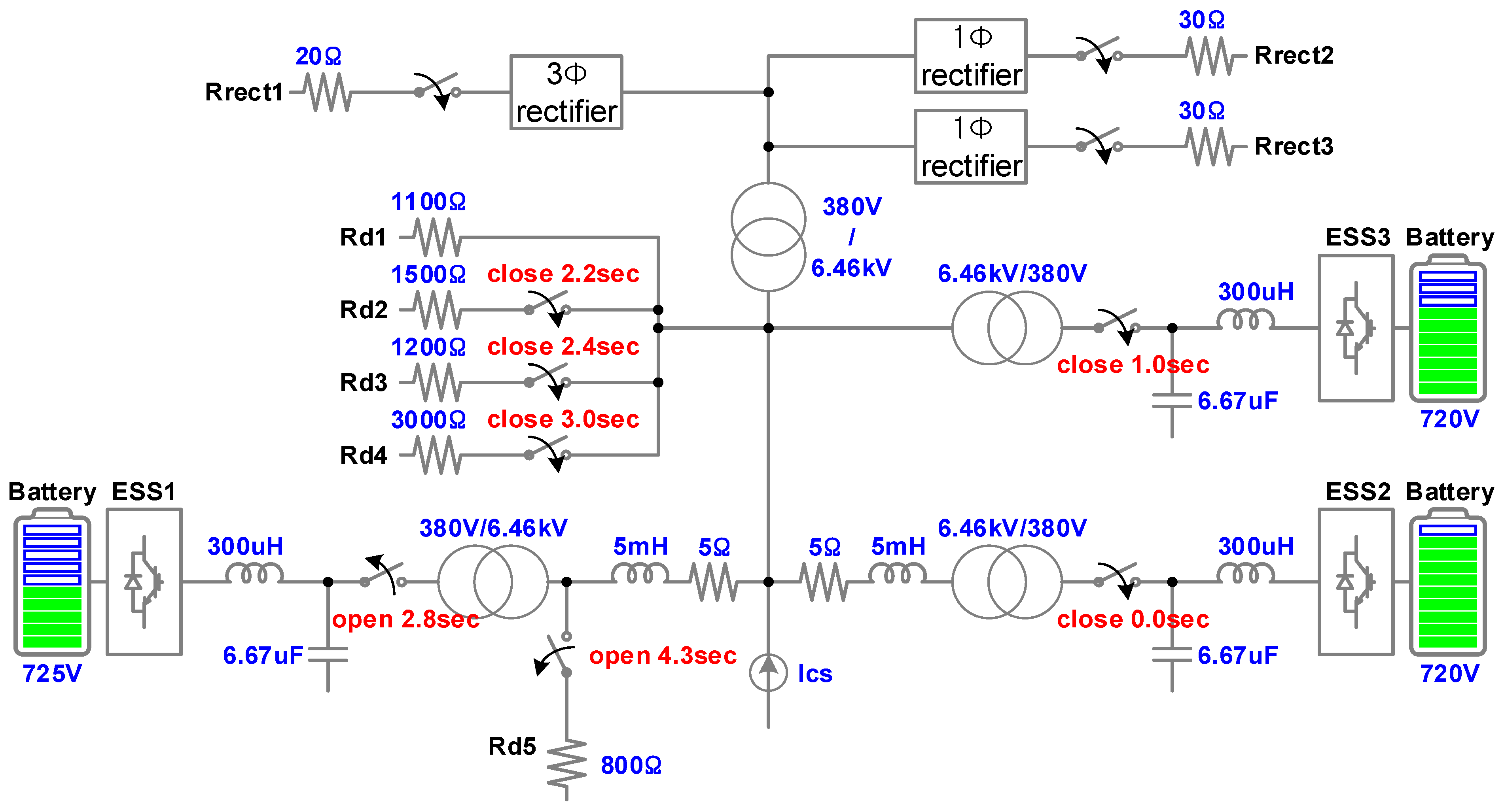
An MG simulation model was developed to verify the proposed control method. The circuit of the MG used in the simulation is shown in
Figure 6.
In order to shorten the simulation time, the simulation model did not include a diesel generator, solar power, or wind power. The devices that controlled the power in connection with the grid were similar to a current source, and a set of three-phase constant current source Ics was used in the simulation model.
The ESS used three sets of 100 kW classes, and they were marked as ESS1, ESS2, and ESS3 in order. ESS1 was designated as the master device and was disconnected from the grid 2.8 s after starting the operation. ESS2 and ESS3 were slave devices, and ESS2 had a higher priority.
The loads were simplified into pure resistive loads and rectifying loads. Two sets of single-phase loads and one set of three-phase loads were used for rectifying loads, and five sets of three-phase resistive loads were used. The load was connected to or disconnected from the grid at a preset time.
The nominal voltage of the ESS was 380 V, and the nominal voltage of the distribution network was 6.46 kV. The leakage impedance of the transformer was 6.5%. In the distribution line, the resistance component predominated.
4.2. Simulation Model
The simulation model to verify the proposed control method is shown in
Figure 7. The configuration of the simulation model was the same as in
Figure 6. The distributed power source consisted of three ESSs (ESS1, ESS2, and ESS3), and the constant current source was indicated by the CS. The ESS controller was implemented as a DLL file, the sampling frequency was 10 kHz, and the PWM frequency was 5 kHz.
The central controller of the MG was not implemented separately, and the active power reference value was designated as a pattern for each device. In addition, the reactive power was set to ‘0’.
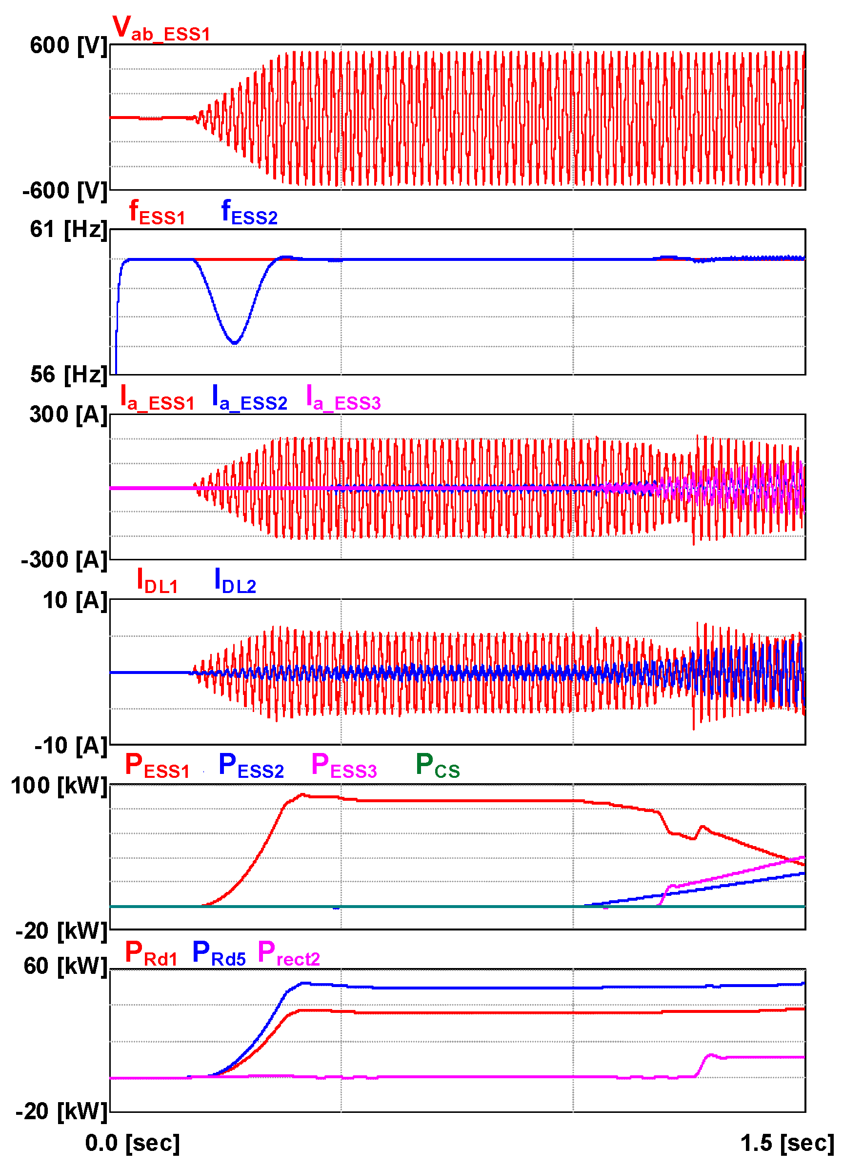
Figure 8 shows the initial startup of the simulation model.
The active power supplied from the three ESSs to the MG was labeled PESS1, PESS2, and PESS3, respectively, the active power supplied from the constant current source was PCS, the active power of the load that consumed the power converted into DC from the rectifier was labeled Prect1, Prect2, and Prect3, and the resistance loads that consumed the AC power were labeled PRd1, PRd2, PRd3, PRd4, and PRd5, respectively.
The master unit ESS1 started working and supplied the voltage Vab_ESS1 to the MG. Even when the master device supplied a constant frequency, the frequency varied slightly as soon as the load or power generation fluctuated in each device. The currents (Ia_ESS1, Ia_ESS2, Ia_ESS3) supplied from each ESS to the MG varied depending on the load of the MG and the operation of each system. Although the current of the slave device was determined according to their active power and reactive power references, the current Ia_ESS1 of the master device was determined according to the demand and supply of active power and reactive power, respectively; thus, it fluctuated rapidly when the load changed or the generating power changed. The current (IDL1, IDL2) flowing through the two sets of distribution impedances of the MG was determined by the state of the ESSs and the loads.


