1. Introduction
In the petrochemical industry, the compressors used for hydrocracking, hydrorefining and reforming work in very aggressive environments. In these harsh conditions, alloy steels cannot operate. In particular, in the hydrocracking process, thus in the presence of water vapor with hydrogen disulfide, compressor impellers are exposed to severe stress corrosion conditions [
1,
2,
3]. That is why precipitation hardening stainless steels, such as 17-4PH and 14-5PH, are chosen for modern hydrogen centrifugal compressors, instead of using alloy steels [
4]. Stainless steels with optimized chemical compositions and after heat treatments have more than good corrosion resistance but also outstanding strength and weldability [
5].
Properties of materials and manufacturing techniques are constantly improved, but despite the know-how growth failures occasionally happen. The root cause seems to be exceptionally complex stress conditions and an aggressive working environment [
3,
6,
7].
The impeller described in the paper is of closed type, made of the 17-4PH martensitic precipitation hardening stainless steel, and is used for hydrorefining. The mechanism of its failure is a subject of this investigation, including optical examination, material testing, theoretical calculations and numerical simulations. Special attention has been given to the material properties, the corrosive environment and the complex stress state.
The considered impeller worked as a first stage wheel of a six-stage compressor. Its failure occurred 4 days after the scheduled overhaul without any observed pre-symptoms. The total operating lifetime of the wheel was estimated to be 80,000 h.
The main objective of this paper is to identify the root cause of the failure. First, the impeller was sent to the Strength of Materials Laboratory, where surface hardness tests were conducted. Second, a numerical analysis based on Finite Element Method was done to assess the influence of each of stress generating features: shrink fit, centrifugal force and keyways. Third, we conducted an investigation of the hypothesis that the acid environmental impact on the 17-4PH stainless steel in presence of high temperatures caused the Sulfide Stress Cracking phenomenon to occur. The ultimate objective was to give post failure recommendations for machine improvement, so prevention countermeasures against failure were suggested.
2. Optical Analysis of the Fracture Surface
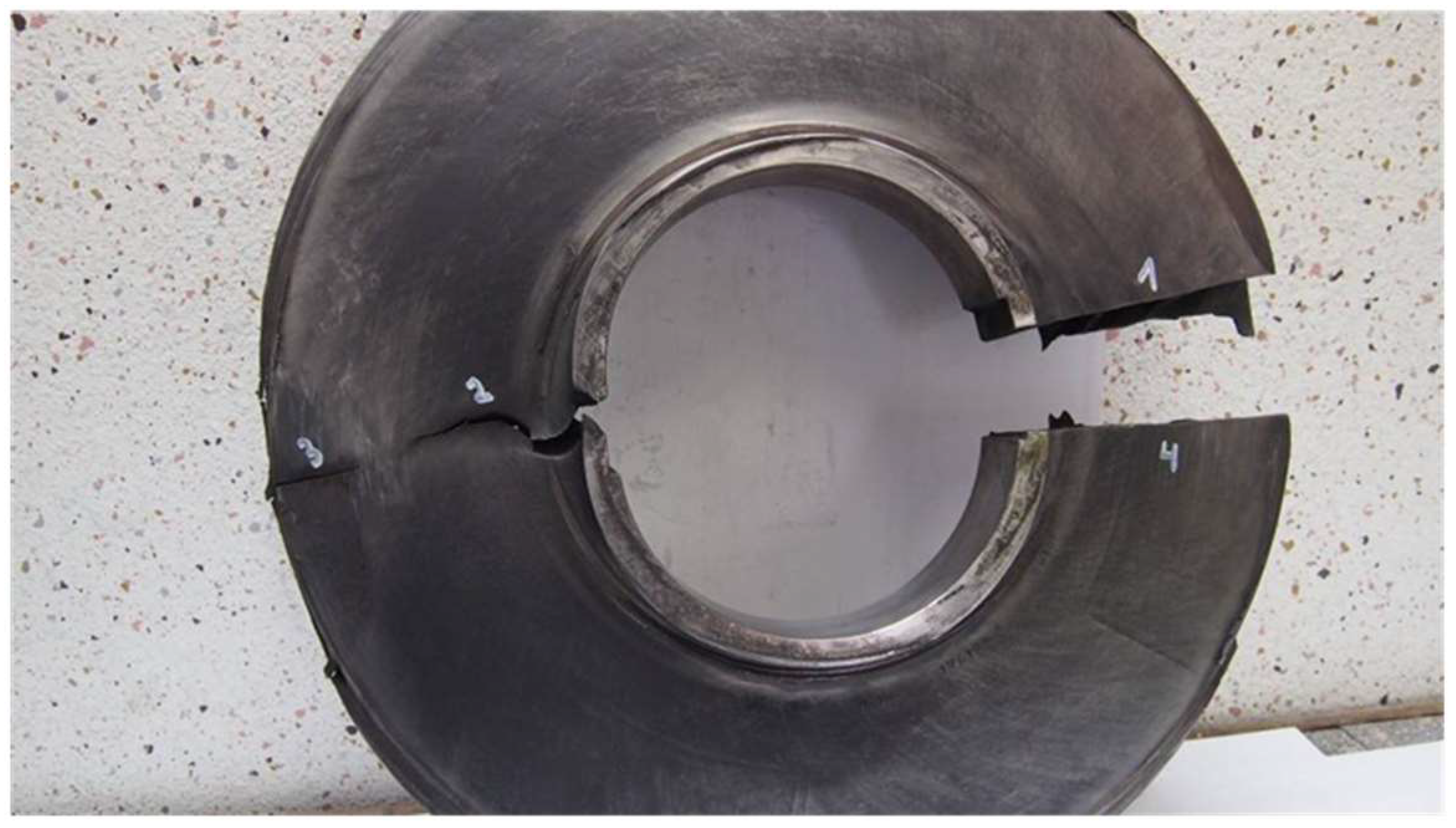
There were six impellers in the compressor and the fracture occurred in the first one, as shown in
Figure 1. Their blades were welded using a technique of slot-welding. Then the impellers were mounted on the shaft with a shrink fit and two keyways.
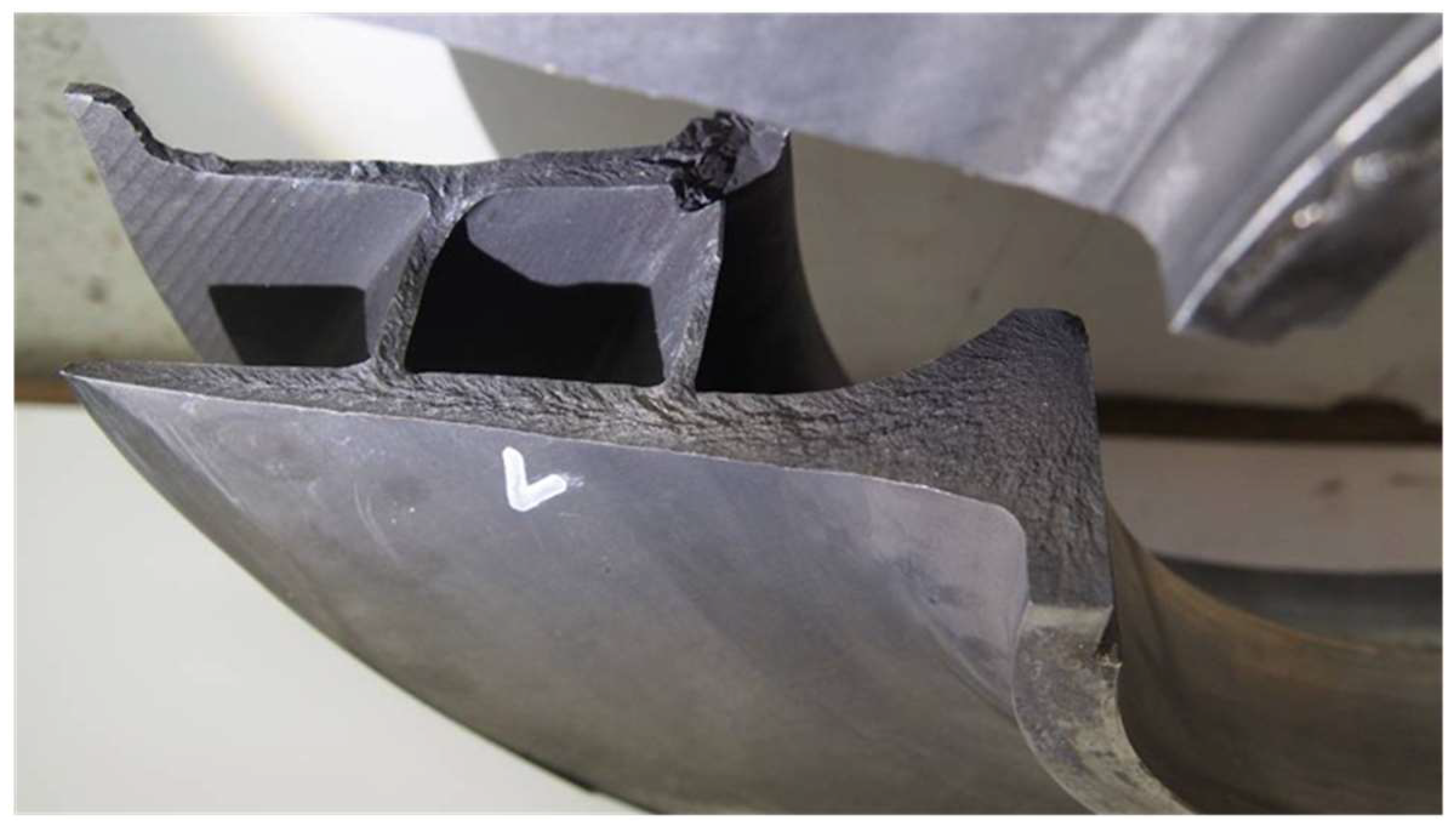
An optical examination of the fracture surface revealed that the crack, initiated from a keyway, propagated diagonally to the external diameter of the impeller wheel. In
Figure 2, in cut view, one can see clear chevron marks pointing towards the origin of failure. This examination revealed that the fracture occurred at first in the center hole and then spread out to the blades and the cover. The Strength of Materials Laboratory, after their examination, identified a brittle fracture without visible prior plastic deformation and confirmed that the keyway corner was the initial point of the crack. Moreover, the local hardness of fracture was estimated at 336–342 of the HV10 scale, which is a much higher value than measured in other points of the damaged wheel.
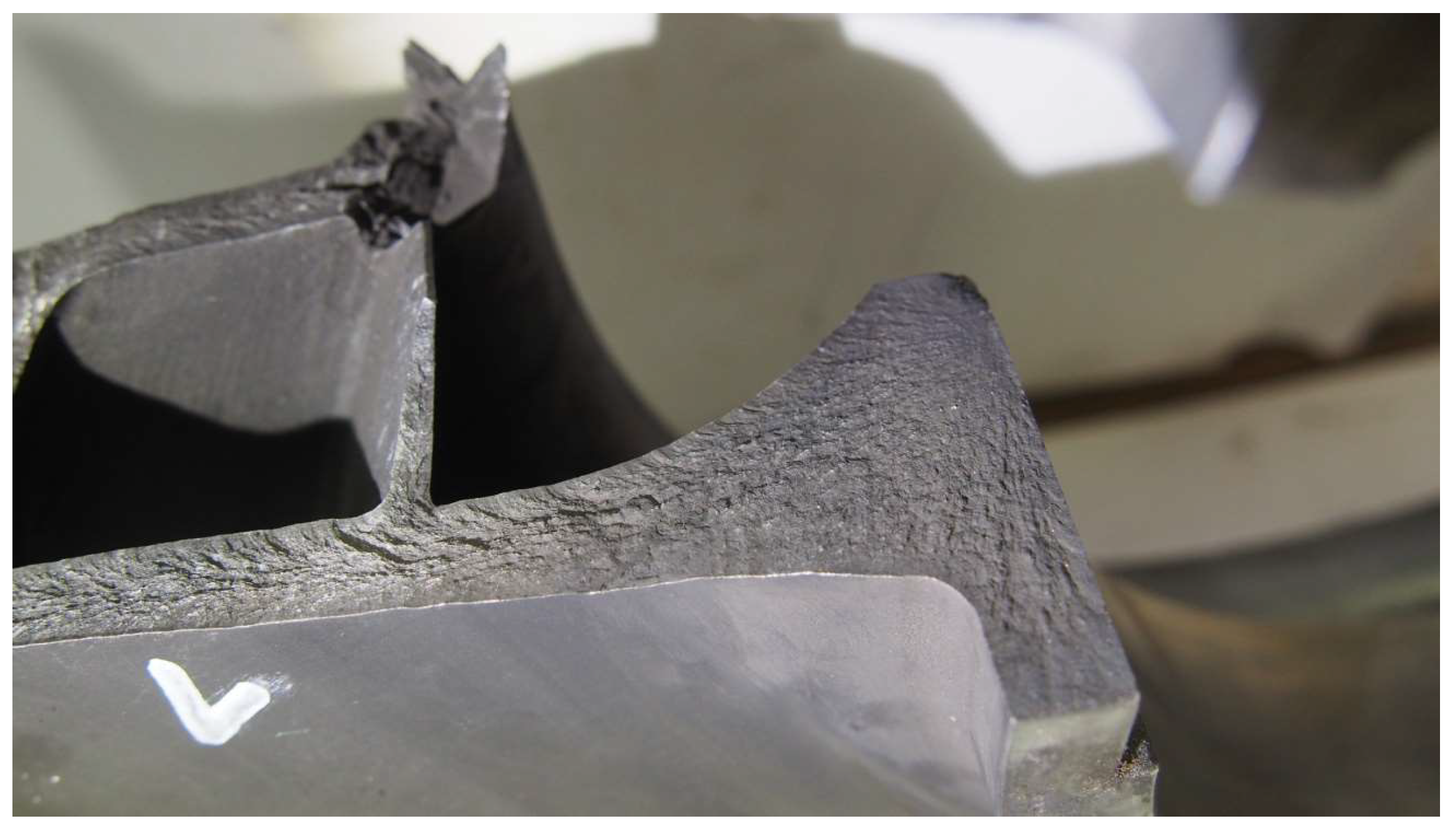
Some important conclusions can be drawn from this fracture surface analysis (
Figure 3), namely the chevron pattern and the way this pattern converges in the suspected point of fracture initiation. There are known other cases of the compressor impeller failure with similar fracture morphology, where the main cause of damage was Sulfide Stress Cracking [
3,
7,
8]. Based on these facts and the local hardening of the section area, it can be concluded that the fracture was caused by excessive fragility resulting from operation in the aggressive environment.
3. Stress Analysis
To confirm the given hypothesis and understand the mechanism of the failure, the stress levels and distribution need to be found. For complex geometries, the use of three-dimensional Finite Element Method analysis is a common engineering practice. In order to model the geometry, a real spare impeller has been scanned using visible light band method. Thanks to 3D scanning, the object was transferred to the computer environment in a short time and with good accuracy. The obtained geometry is shown in
Figure 4. One cannot forget that the impeller was mounted on the shaft with two keyways. However, the exact radius of keyways corners could not be found from the 3D scanning technique, so it was assumed to be 0.5 mm.
The material properties assigned for the 3D geometry were those of precipitation hardening stainless steels 17-4PH, namely: d = 7850 kg/m3—material density, ν = 0.3—Poisson’s ratio and E = 2 × 10⁵ MPa—Young’s modulus.
The applied boundary conditions corresponded to those of the shrink fit and nominal rotational speed. The design shrink fit of this rotor was relatively high—approximately 2‰ with the shaft diameter of ϕ175 mm. In absolute numbers, the exact value of the difference between the shaft and sleeve diameters was equal to 0.34 mm. The given nominal speed of the compressor was equal to 9300 rpm.
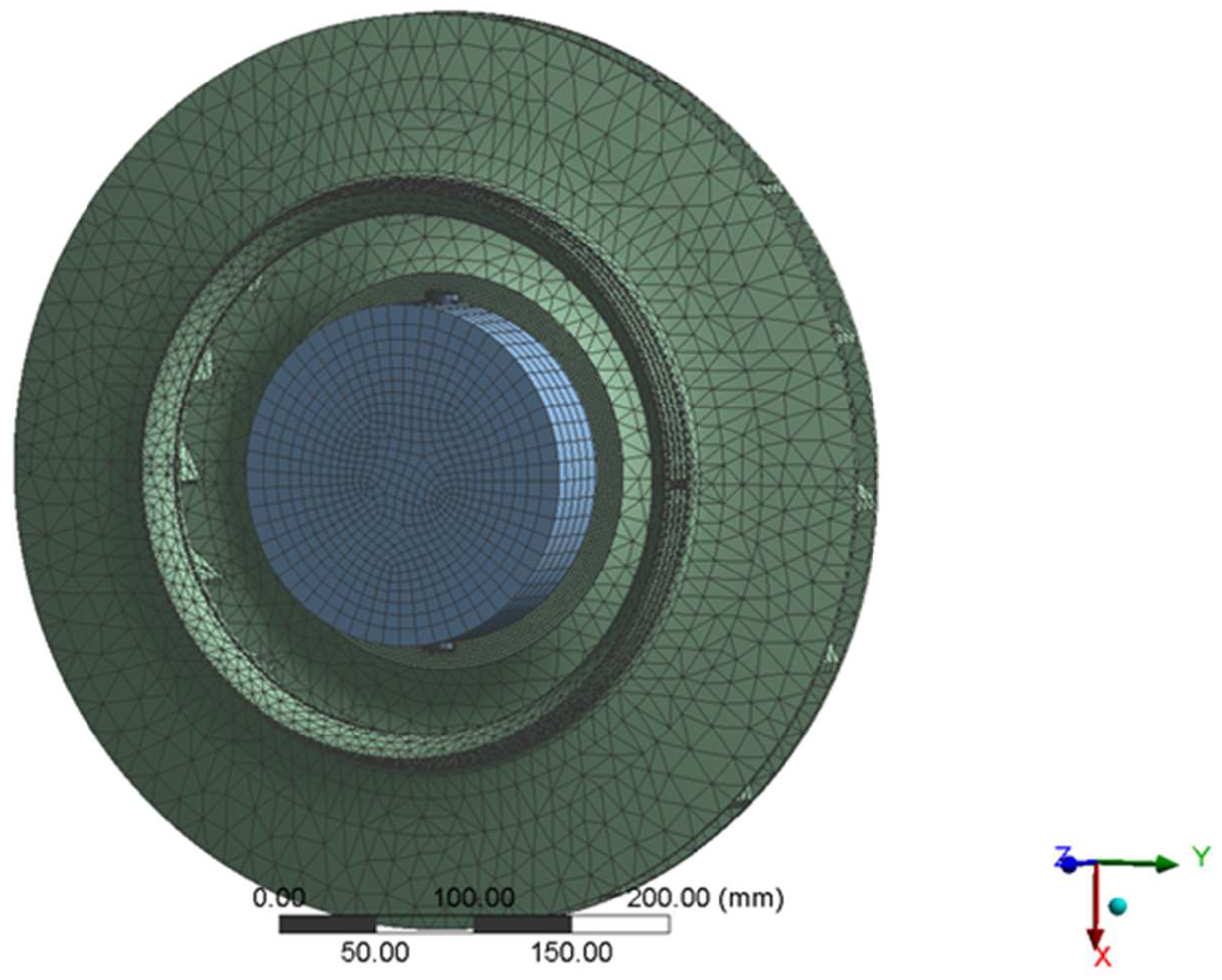
A mesh of the model is presented in
Figure 5. It consisted of 185,403 nodes and 62,670 elements. The mesh was mainly an unstructured grid with high enough mesh density in chamfers and corners to reveal expected stress concentration.
To estimate the stress distribution in the impeller, the superposition method was used. The multistep numerical analysis was performed, including following consecutive steps:
Estimation of stresses induced by the shrink fit—no keyways taken into consideration;
Estimation of stresses caused by the centrifugal force;
Estimation of stresses induced by the shrink fit—keyways taken into account;
Superposition of all the conditions—stresses induced by the centrifugal force, keyways and the shrink fit.
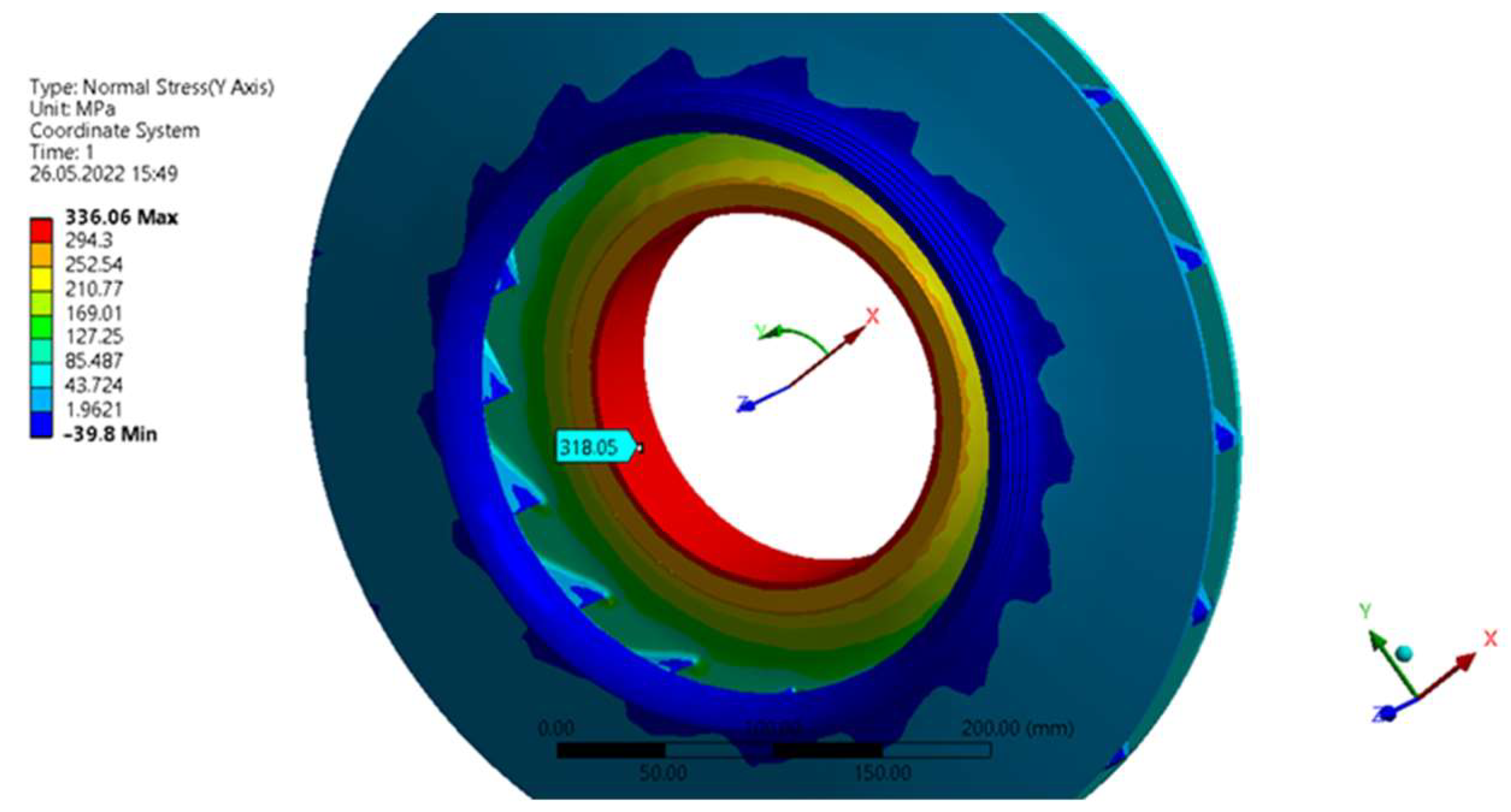
In the first step only the shrink fit was taken into account. This load condition was applied to the model by means of the diameter difference between the shaft and the sleeve. In
Figure 6 the equivalent stress distribution is shown. Its maximal value in the inner chamfer, where the stress concentration occurs, was equal to 336 MPa. In the fitting surface the equivalent stress value was around 318 MPa.
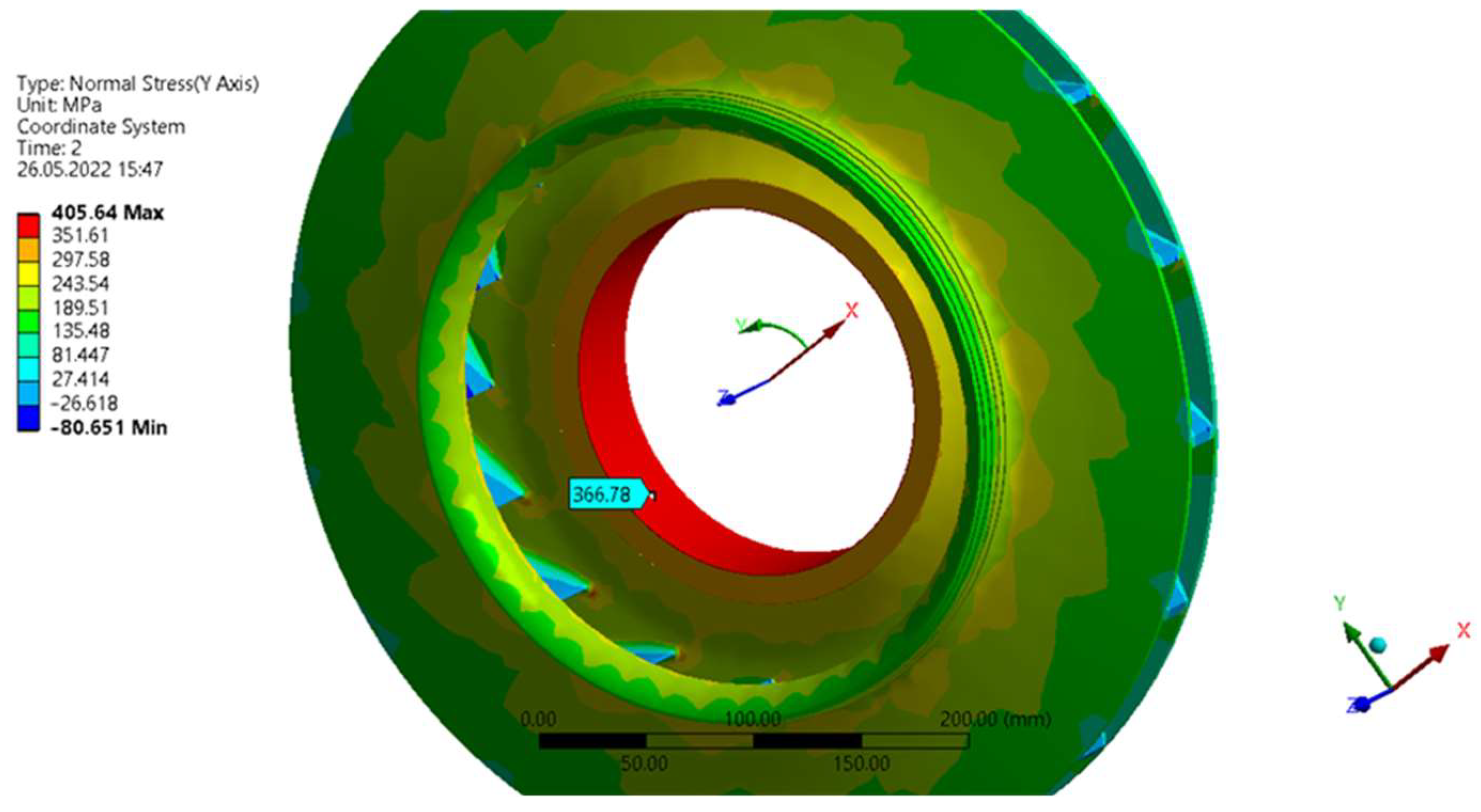
In the second step, both the shrink fit and the centrifugal force were applied to the model. The von hoop stress distribution for these conditions is presented in
Figure 7. Its exact maximal value was 406 MPa, which corresponds to 59% of the yield stress (
σg = 689 MPa). In the fitting surface though, the hoop normal stress value was around 366 MPa, slightly greater than in the first step without centrifugal force acting on the rotor.
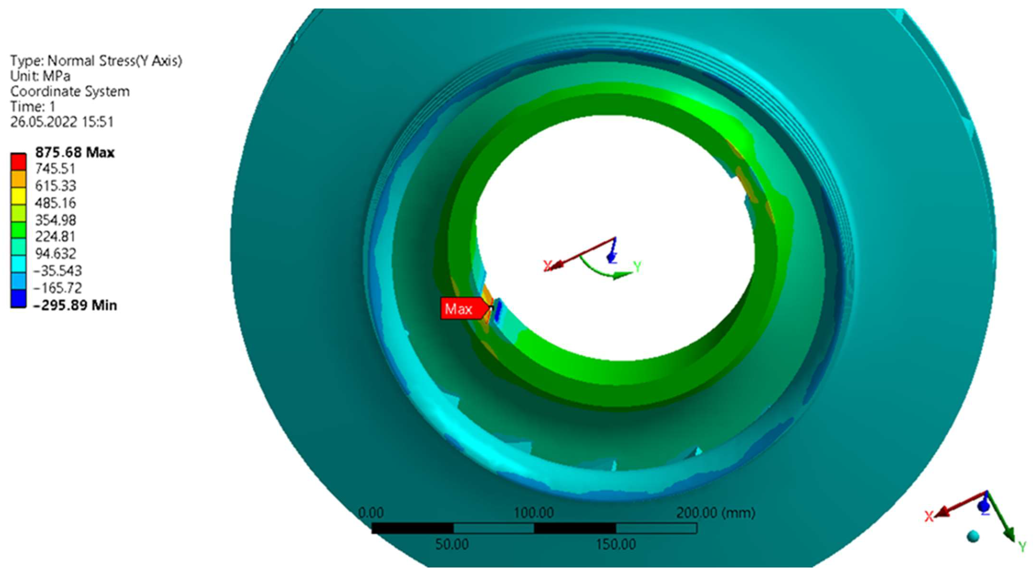
In the third case the shrink fit was taken into account, the same as in the first step but this time two keyways were extruded from the model. The hoop normal stress distribution for this simulation is presented in
Figure 8, where the stress level value reached 322 MPa on the fitting flanges. Special attention should be paid to the keyway corners where the stress concentration occurs, indicating the highest stress levels. However, its value is strongly dependent on mesh density and keyways corners radius, the latter only assumed and not precisely measured, so the result presented here is more of qualitative and not quantitative importance.
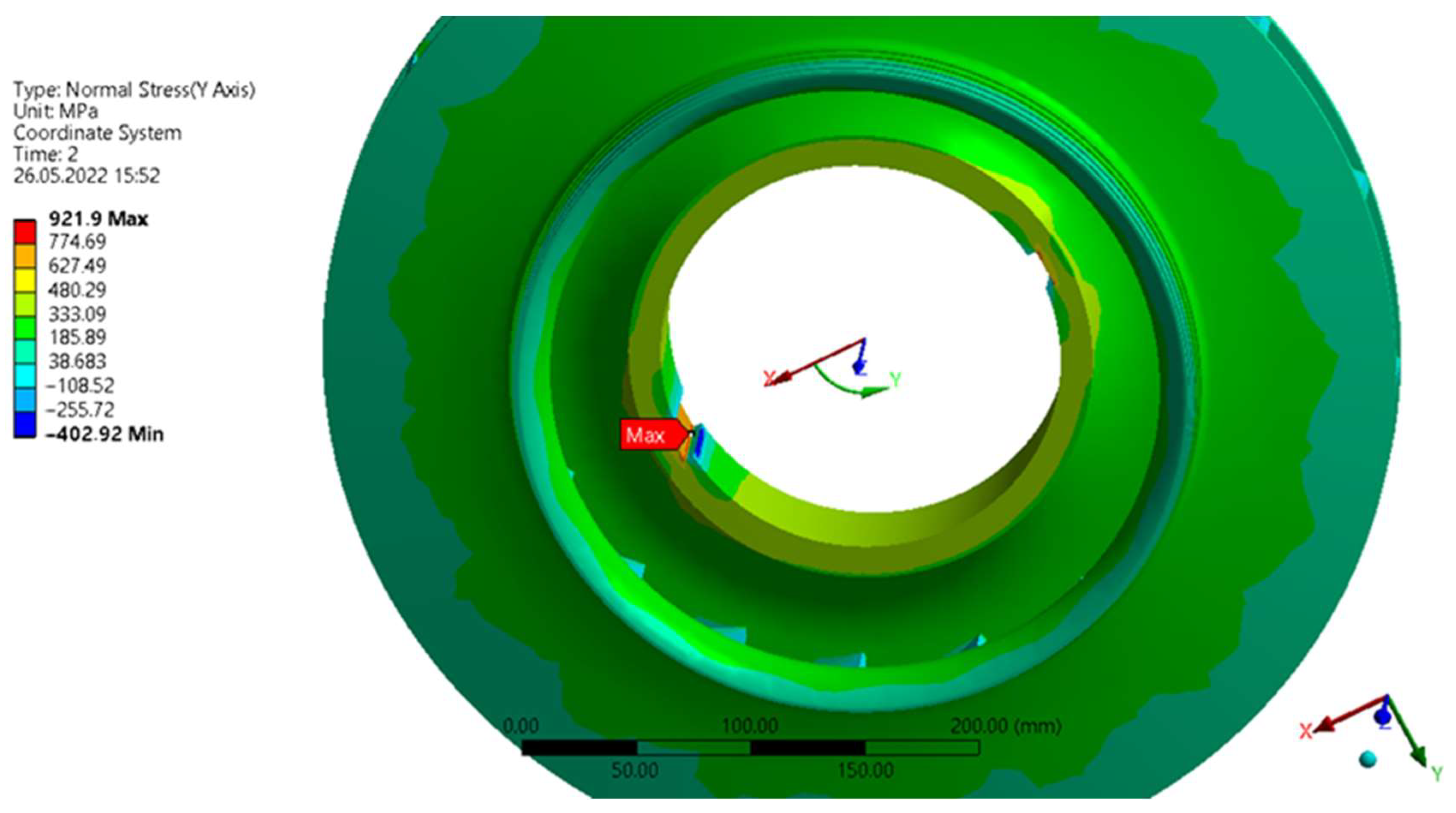
Finally, the last step of the simulation was superposition of the total loading: shrink fit, centrifugal force and keyways. The hoop stress distribution for this complex state is presented in
Figure 9. The results show that the stress level in the fitting flange was equal to 394 MPa, which corresponds to 57% of the yield stress for the 17-4PH material, an important stress concentration still being predicted in keyway corners.
To conclude the numerical analysis results, the method of assembling the impeller on the shaft is probably overdone, meaning that the use of both the tight shrink fit and two keyways is excessive and introduces significant stress levels, especially stress concentration in keyways slots. The impeller design should have been optimized in terms of stress levels and the shrink fit tightness, as well as keyways design and number being parameters of the optimization.
The analysis step by step allowed us to evaluate the influence of each loading state on stress levels. The obtained numerical results confirm undoubtedly the hypothesis that the stress concentration in the keyway corner was the cause and the starting point of the failure mechanism.
4. Influence of the Working Fluid on the Failure
The machine under analysis is a six-stage compressor operating in the hydrocracking installation. We have limited choice of materials to manufacture parts for turbomachines working in aggressive environment, namely destructive fluids. According to standards, ISO 15156-1 or the corresponding American NACE MR0175 [
9], 17-4PH steel material is commonly applied in many aggressive environments due to its high yield stress and corrosion resistant properties. Nevertheless, there are publications where it has been shown that this steel is susceptible to Sulfide Stress Cracking under specific environment conditions [
10,
11].
Sulfide Stress Cracking is a phenomenon requiring three factors to occur, namely: a corrosive medium, a susceptible material and a constantly present significant stress state. The damage caused by this process is mostly sudden and unpredictable. The failure can occur after hours, months or even years of normal exploitation.
The problem of stress concentration was described in chapter “Stress analysis”. In this chapter, we take a closer look at the working fluid influence on the failure.
The components of the working medium were mainly hydrogen (90.2% vol.), methane (4.2% vol.), hydrogen disulfide (3.7% vol.) and other hydrocarbons (the remaining part). Also, from the process point of view, a certain amount of water vapor is acceptable in the working medium (up to 0.12% of the molar fraction). All these data indicate that the compressor works with a relatively acid medium, since the presence of H2S causes a low pH. The acid environment, under some conditions, can induce hydrogen absorption by the metal and thus, as a result, the phenomenon referred to as hydrogen embrittlement.
Not only the composition of the working fluid but also its pressure has a significant role in the Sulfide Stress Cracking phenomenon. It is even more likely to occur when the working medium is at a pressure of 0.448 MPa or higher and when the partial pressure of H2S in the mixture is higher than 0.545 kPa. In the compressor under consideration, both conditions were fulfilled.
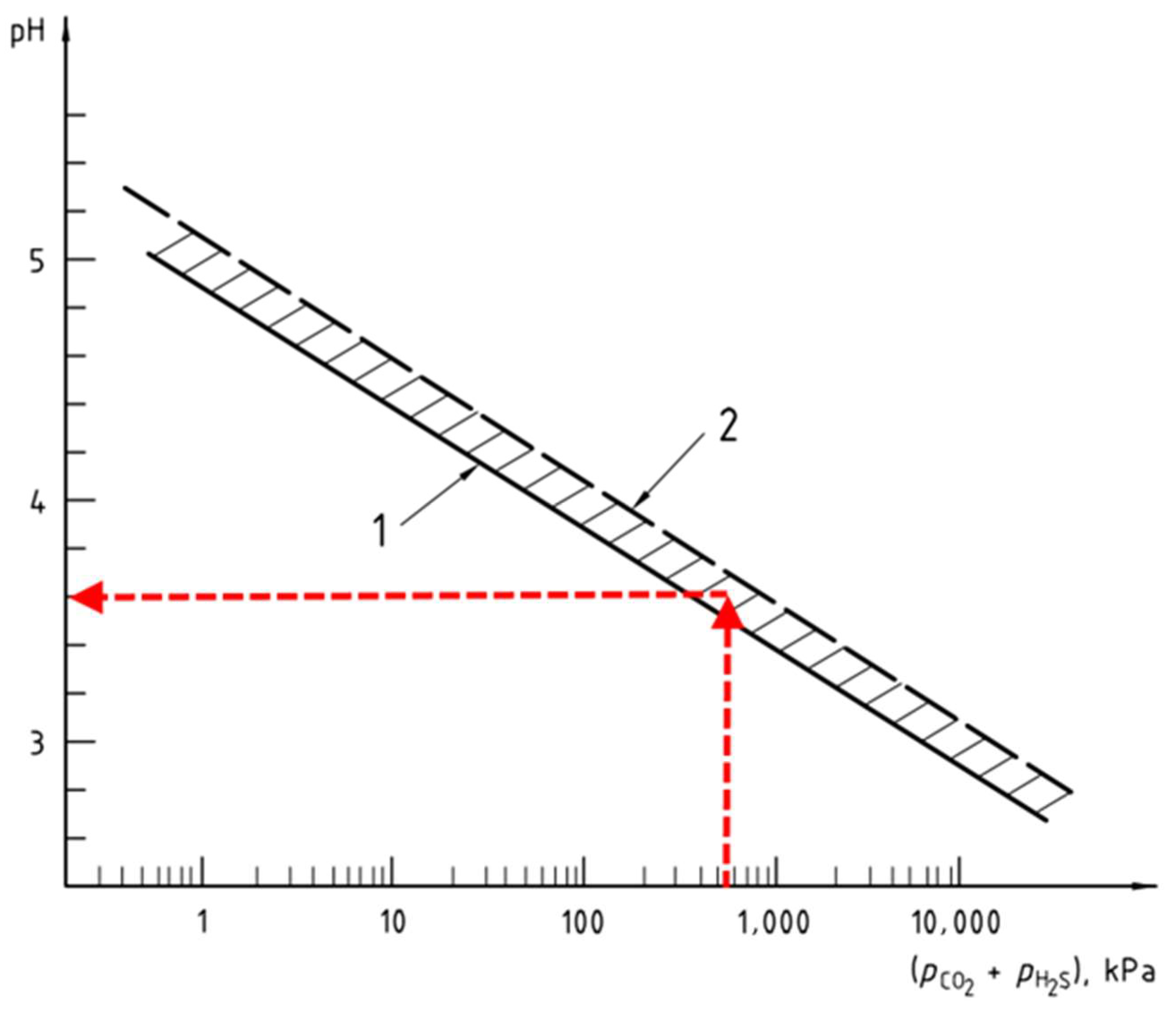
Thus, according to ISO 15156-1, chapter 7.2.1.2, both parameters (the fluid acidity and its pressure) need to be taken into account to evaluate a threat of failure due to the Sulfide Stress Cracking (SSC). This is achieved first by finding the pH level based on partial pressures of H
2S and carbon dioxide (CO
2) in the working medium. In our case, there was no CO
2 fraction in the medium under analysis, only hydrogen disulfide with a partial pressure of 545 kPa to be considered. For this pressure, the acidity of pH = 3.5 was read (
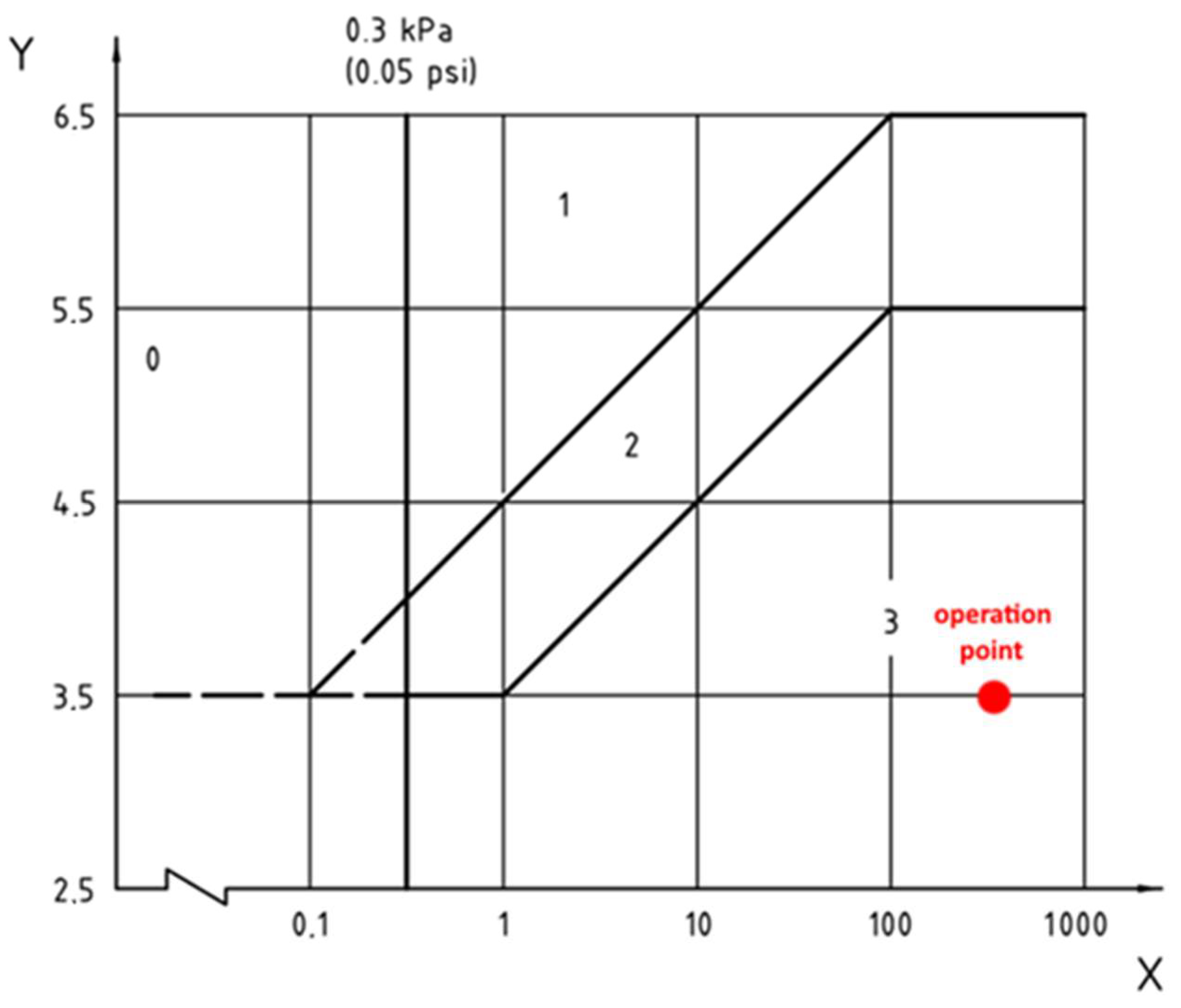
Figure 10). Second, the compressor operation point can be found by transferring this information to
Figure 11, where four regions are indicated based on partial pressures of H
2S and pH of the environment.
The chart presented in
Figure 11 describes four possible levels of environment aggressiveness, namely:
SSC Region 0, where the H2S partial pressure is lower than 0.3 kPa. The choice of steel in this region requires no special precautions;
SSC Region 1, where the H2S partial pressure is higher than 0.3 kPa. There is a minimal risk of steel cracking;
SSC Region 2, where the H2S partial pressure is higher than 0.3 kPa. There is a risk of steel cracking;
SSC Region 3, where the H2S partial pressure is higher than 0.3 kPa. The steel is especially susceptible to stress corrosion.
The compressor in the case under consideration was operating in Region 3.
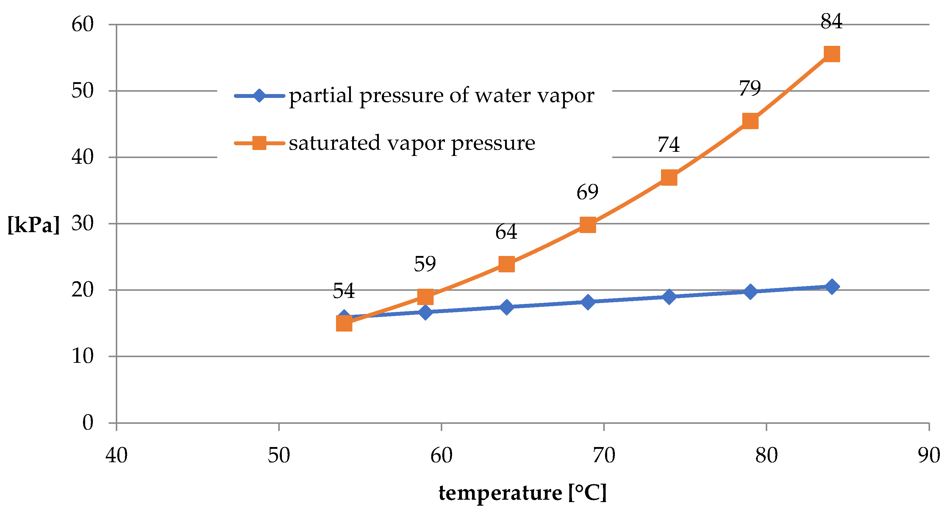
The presence of dry hydrogen disulfide favors development of the Sulfide Stress Cracking process but there is more. Some investigations [
3] suggest that the additional presence of liquid H
2O can rapidly increase the crack development. The chart shown in
Figure 12 presents the partial pressure of water vapor and saturated vapor at inlets of the consecutive compressor stages. It can be observed that at the first stage inlet, the temperature was 54 °C. Under these conditions, the partial pressure of water vapor is higher than the saturated vapor pressure. This indicates the condensation of the liquid H
2O phase and thus, the compressor first stage impeller might be in contact with humid and acid hydrogen disulfide.
5. Influence of the Temperature
17-4PH is martensitic precipitated hardening stainless steel. The final material yield stress and surface hardness depends on the hardening temperature. The ISO 15156-1 standard limits the permissible surface hardness to 33 HRC, which corresponds to 328 HV. After the failure, the Strength of Materials Lab measured the hardness of the material sample taken from the impeller inner sleeve to be equal to 332 HV. That value approached the limit advised by the ISO 15156 standard.
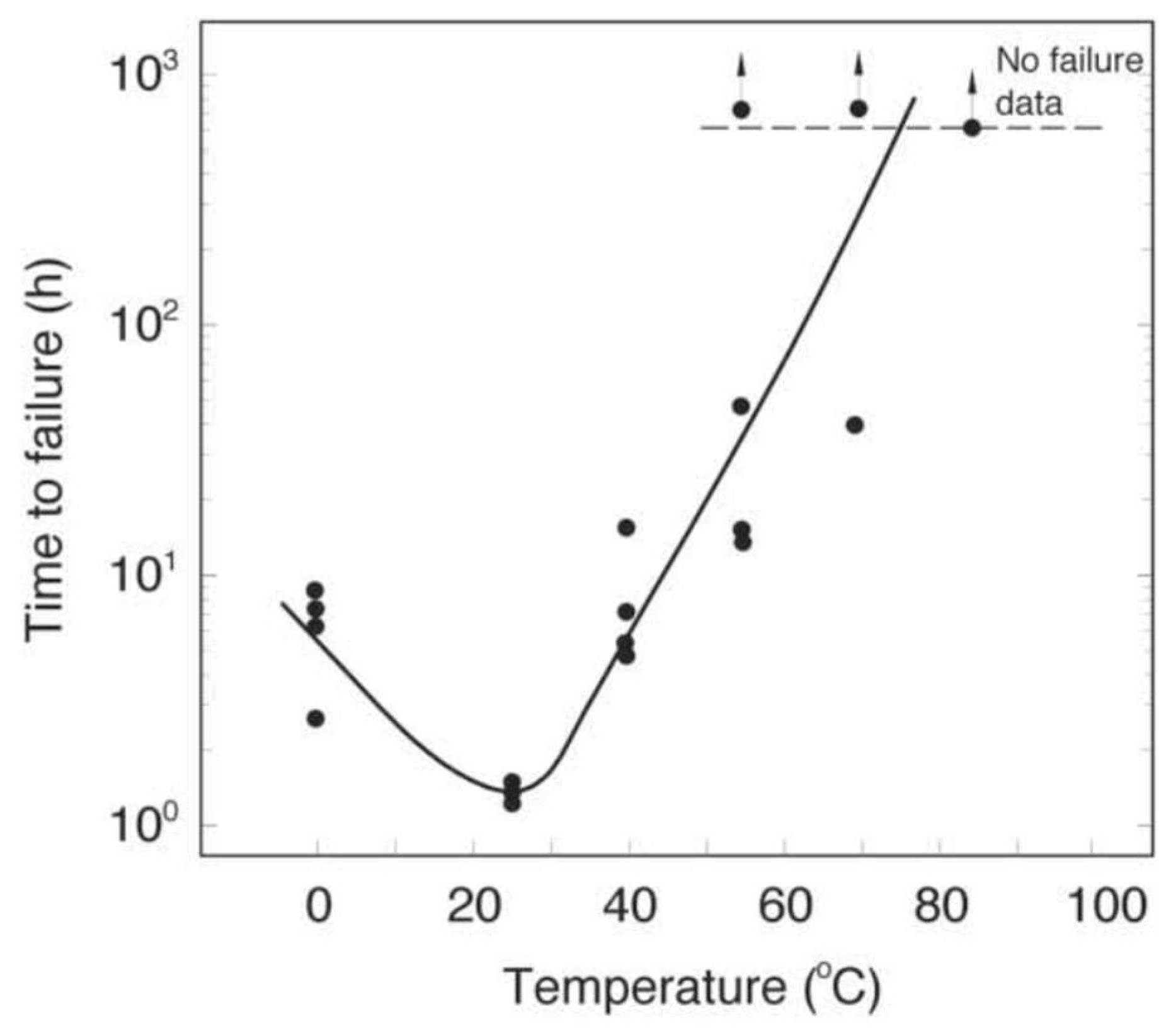
The steel resistance to Sulfide Stress Cracking is highly dependent on the temperature of the working medium. The chart presented in
Figure 13 shows an influence of the environment temperature on the mean time to failure of a sample. The sample under testing was made of high-yield steel and subjected to an aggressive H
2S environment. A conclusion can be drawn from this chart that martensitic stainless steels have the lowest resistance to SSC at 25 °C. For higher temperatures, up to 80 °C, the mean time to failure increases, and above this temperature level, no failures were observed.
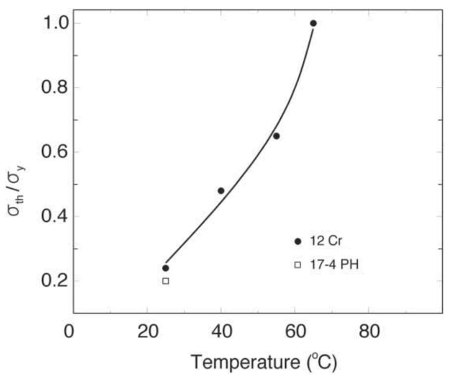
A similar conclusion can be drawn from the chart in
Figure 14, which presents a relation between the temperature and the minimal permanent stress level (as a fraction of the yield stress) as the condition promoting the SSC occurrence. For the compressor inlet temperature (54 °C), the permissible stress level is equal to 55% of the yield stress.
Considering the stress levels presented in
Section 2, the impeller is not particularly exposed to the risk of failure. However, it should be noted that a high concentration of stress occurs in the keyway corners and these points are especially prone to Sulfide Stress Cracking.
6. Conclusions
The conducted failure analysis consisted of the optical analysis, the finite element method stress analysis and the evaluation of the working fluid influence according to the ISO 15156 standard, as well as temperature influence on the Sulfide Stress Cracking of 17-4PH martensitic precipitated hardening stainless steel. The analysis allows us to draw several conclusions.
First, the stress analysis suggests the presence of a high level of stress concentration in the keyway corners. Its value could not be calculated with a high level of confidence but from conducted simulations it was over 900 MPa. From a design point of view, the original shrink fit should be sufficient to transfer the torque from the shaft to the impeller. The presence of the keyways weakens the shrink fit and introduces heterogeneity of the stress distribution in the matching surfaces of the shaft and the sleeve.
According to the ISO 15156 standard, the steel the impellers were made of is especially exposed to Sulfide Stress Cracking induced by the working medium. The damaged first stage wheel was working in an acid, humid environment of H2S, at the partial pressure of 545 kPa, which is known to be an initiator of SSC in 17-4PH steel. A negative impact was even reinforced by the inlet gas temperature in this stage (54 °C, for which the partial pressure of water vapor was higher than the saturated vapor pressure.).
The impeller surface hardness equal to the ISO 33 HRC limit indicates that the material of the wheel is susceptible to SSC. Increased hardness in the fracture surface (35 HRC) indicates that the embrittlement process had already taken place in the impeller material.
On the basis of the above statements, it can be concluded that the presence of the following unfavorable conditions was highly probable:
The aggressive environment containing humid hydrogen sulfide at the partial pressure of 545 kPa;
Permanent stress concentration in the keyway corners: over 900 MPa of hoop normal stress;
The use of 17-4PH stainless steel prone to SSC as the impeller material may have contributed to the crack failure of the first stage compressor impeller wheel due to the Sulfide Stress Cracking phenomenon.
To avoid similar compressor failures in the future, it is advised to redesign the way the impeller is mounted on the shaft or select a different material for the impeller wheel in accordance with the ISO 15156-3 standard. Those will be the subject of further investigations.
As an alternative to the above-mentioned suggestions, a surface treatment in a low temperature plasma nitriding process can be considered [
12,
13]. This treatment introduces compressive stresses to the material and, thus, removes one of three necessary factors for Sulfide Stress Cracking to occur.


