1. Introduction
The utilization of active magnetic bearings in rotating machines has increased over the past years. They are used in applications where they have advantages over the rolling-element bearing and fluid-film bearing types. Some of the main advantages of the active magnetic bearings are their oil-free operation and their higher mechanical efficiency. Lubrication is not needed for these bearings. Contact between the rotor and stator also do not occur during the operation of these bearings. Another major advantage of the magnetic bearings over the conventional bearing types, from the rotor dynamics viewpoint, is the possibility of the dynamic characteristics to be varied without changing the dimensions of the rotor or bearing. The dynamic characteristics of the magnetic bearings are governed by the parameters of their controllers. By varying these parameters, the dynamic characteristics of these bearings can be changed over a considerably wide operating range. A major disadvantage of the active magnetic bearings is their highly nonlinear characteristics, which are attributed to several inherent sources.
The main causes of nonlinear behavior in magnetic bearings are the relationship between the magnetic-bearing force with the coil current and the air gap between the rotor and the stator. The force is inversely proportional to the square of the air gap and proportional to the square of the current in the coil. Another cause of nonlinearity in these bearings is the cross-coupling that arises from the magnetic forces that act in the two orthogonal directions. Cross-coupling forces may occur in these bearings due to the geometry of the magnetic-bearing actuators, the effect of gyroscopic motion, and the effect of the eddy current in the magnetic actuator. Other sources of nonlinearities in magnetic bearings include hysteresis and saturation of the magnetic core material. The nonlinear nature of the active magnetic bearings usually results in non-synchronous vibration in the response of the rotor supported by them for certain ranges of the design and operating parameter values. Non-synchronous vibrations, which induce cyclic stresses, should be prevented in the rotating machines’ operations. Cyclic or fluctuating stresses may shorten the fatigue life of the machine components and may eventually result in their failure.
Due to being open-loop unstable, magnetic bearings require feedback control for stable operation. The most common control strategy used for field applications of magnetic bearings is the linear proportional-integral-derivative (PID) controller [
1]. The effective working operation of the PID controller is however limited to the proximity of the equilibrium point where the linearization of its dynamics is performed. Deviation of the magnetic-bearing operation from the equilibrium point may render the PID controller to be ineffective. Such deviation may occur in the field operation of rotating machines mounted in magnetic bearings due to the occurrence of large forces acting on these machines. Some of the common causes of these forces include rotor imbalance and flow-induced vibrations, amongst others. Works in the past have proposed various nonlinear control techniques to address the occurrence of nonlinear vibrations in magnetic bearings. A brief review of the applications of these techniques, in particular the fuzzy logic and sliding mode control (SMC) schemes, to the control of magnetic bearings follows. The recent paper by Srinivas et al. [
2] may be referred to for a more exhaustive review of the application of magnetic bearings in rotating machines. Huang et al. [
3], on the other hand, provides a focused review on the control technology for magnetic bearings.
An adaptive fuzzy scheme was employed by Liebert [
4] in magnetic-bearing application. In this scheme, the gains of the linear PID controller were varied using fuzzy logic. Measurements undertaken on a magnetic-bearing-test rig demonstrated that the proposed scheme had a better step response when compared to the use of the conventional linear PID controller. Hung [
5] proposed the use of a variable structure scheme to control the motion of a single-axis magnetic-bearing system. This scheme made use of two different controllers. For operation in the vicinity of the equilibrium point, a linear PID controller was used. A nonlinear feedback-linearizing controller was utilized for the operation of the bearing away from the equlibrium point. In order to have a seamless transition between these two controllers, a fuzzy control scheme was used. The fuzzy control scheme proposed in this work was also utilized to prevent chattering from occuring in the response of the system. The Takagi–Sugeno–Kang fuzzy model was utilized by Hong et al. [
6] in the development of a scheme to control nonlinear vibrations in magnetic bearings. The scheme was found to perform better compared to the single operating point linear controller based on the outcomes of numerical studies. The magnetic bearing’s regime of stable operation was also found to be at a maximum with the use of the proposed scheme. Experimental work undertaken by Hong and Langari [
7] also confirmed the superior performance of the proposed control scheme [
7]. Hong and Langari [
8] further extended their proposed control scheme and demonstrated that this scheme was robust to parameter uncertainties and disturbances that were harmonic in nature. The effective performance of this control scheme was further demonstrated through numerical simulation as well as measurement on an experimental setup. Kosaki et al. [
9] proposed a multivariable fuzzy controller for rotors mounted on magnetic bearings subjected to cross-coupled gyroscopic motion. The proposed control scheme was found to be able to maintain the system’s performance when the speed of the rotor was varied and when external disturbance was imposed on it. The numerical work of Lei et al. [
10] on the utilization of a magnetic bearing as an exciter for an active rotating-stall control test rig showed that the proposed fuzzy logic controller used for this purpose was able to provide a whirl orbit of prescribed magnitudes. The work further showed that the whirl orbit radius that the fuzzy logic controller was able to generate was much higher than that obtained using a conventional PD controller. Du et al. [
11] has proposed a fuzzy-control strategy based on the Takegi–Sugeno model [
12] to stabilize a single-axis magnetic-bearing system with fast-response speed subjected to parameter uncertainties and saturation of the control voltage. Numerical simulations, used to ascertain the effectiveness of this control scheme, showed the robustness of this scheme to uncertainties in the active magnetic-bearing-model parameters. Shi and Lee [
13] compared the performance of a fuzzy logic controller with a model-based controller for the stabilization of an experimental magnetic-bearing setup. They found that the fuzzy logic controller was more robust and had a better performance in rejecting disturbances compared to the model-based controller. Noshadi et al. [
14] proposed time-domain objective functions, which were used to tune the design parameters of a PID-type fuzzy. They further performed experiments on a laboratory-based active magnetic-bearing system and showed that the PID-type fuzzy controllers, which maintained lower profiles of control signals, had better performance as compared to the linear on-board controllers. Nguyen et al. [
15] reported work on a fuzzy logic controller for magnetic-bearing application. The magnetic-bearing system’s mathematical model was the basis for the fuzzy controller’s membership functions and rule design. The proposed control algorithm was numerically evaluated, and the outcome revealed its effectiveness in controlling the response of the rotor. Specifically, the controller demonstrated its effectiveness in suppressing steady-state and transient responses of the rotor. A novel design procedure for a neuro-fuzzy controller of a magnetically supported rotor based on optimal robust control was proposed by Carvalho et al. [
16]. The tuning of this controller considered the optimal balance between vibration attenuation and robustness, which was carried out using the robust optimization procedure. Evaluation of the unbalance response of the rotor revealed the effectiveness of the proposed procedure.
For nonlinear systems, robust control techniques, such as the SMC, have also been used for magnetic-bearing applications. This control scheme accommodates the variability and un-modeled dynamics of the system. In this control scheme, the control problem of a multi-state control system is reduced to a control problem of a first-order control system [
17]. For a simple control structure, the performance of this scheme is satisfactory. This control scheme has been utilized by Yeh et al. [
18] and Rundell et al. [
19] to address issues of nonlinear vibrations in magnetic-bearing systems. Maslen and Montie [
20] have contended that there is no added advantage of using the sliding mode scheme over the the PID controller for vibration control in the magnetic-bearing system. On the other hand, Allaire and Sinha [
21] have shown the robustness of SMC schemes to plant uncertainities. Tian et al. [
22] have further demonstrated the robustness of this control scheme to address disturbances in the flexible rotor model. For first-order systems, Foust et al. [
23] showed that the SMC scheme is equivalent to the bang-bang control scheme. The control activities are regulated by the SMC through a bang-bang controller to obtain time-optimal control. By switching between the two opposite extremes, the bang-bang controller provides minimum-time control [
24]. Yao and Chen [
25] proposed a deep convolutional neural network—an SMC scheme for the trajectory control of a rotor mounted on magnetic bearings. The sliding mode scheme was used to obtain the tracking control with high robustness. The deep convolutional neural network, on the other hand, was used for the compensation of the system’s uncertainties. Numerical simulation undertaken on a five-degree-of-freedom rotor-magnetic-bearing system model showed the effectiveness of the proposed control scheme. Magnetic-bearing controllers based on the sliding mode scheme and neural network algorithm was also presented by Cao et al. [
26]. The SMC scheme was utilized to increase the robustness and response speed of the system. The neural network algorithm, on the other hand, provided online tuning for compensation of unmodeled uncertainties and external disturbances. Numerical simulation was carried out to examine the effectiveness of the proposed control scheme against the PID controller. Numerical results showed superior performance of the proposed control scheme over the PID controller. In order to overcome the problem of high-frequency chattering of the conventional SMC scheme, which affects the operational stability of rotors mounted in active magnetic bearings, Wang et al. [
27] proposed a second-order SMC algorithm. Lyapunov criterion [
28] was used to prove the stability of the proposed SMC scheme. Numerical simulation results revealed that the high-frequency chattering was absent in the response of the rotor with the use of the proposed control scheme. Experimental results from a test rig that employed this control scheme further showed that the stability time of the magnetic bearing was decreased by 50%, and the axis trajectory range was reduced by 41.5% as compared to the use of the SMC with exponential-reaching law.
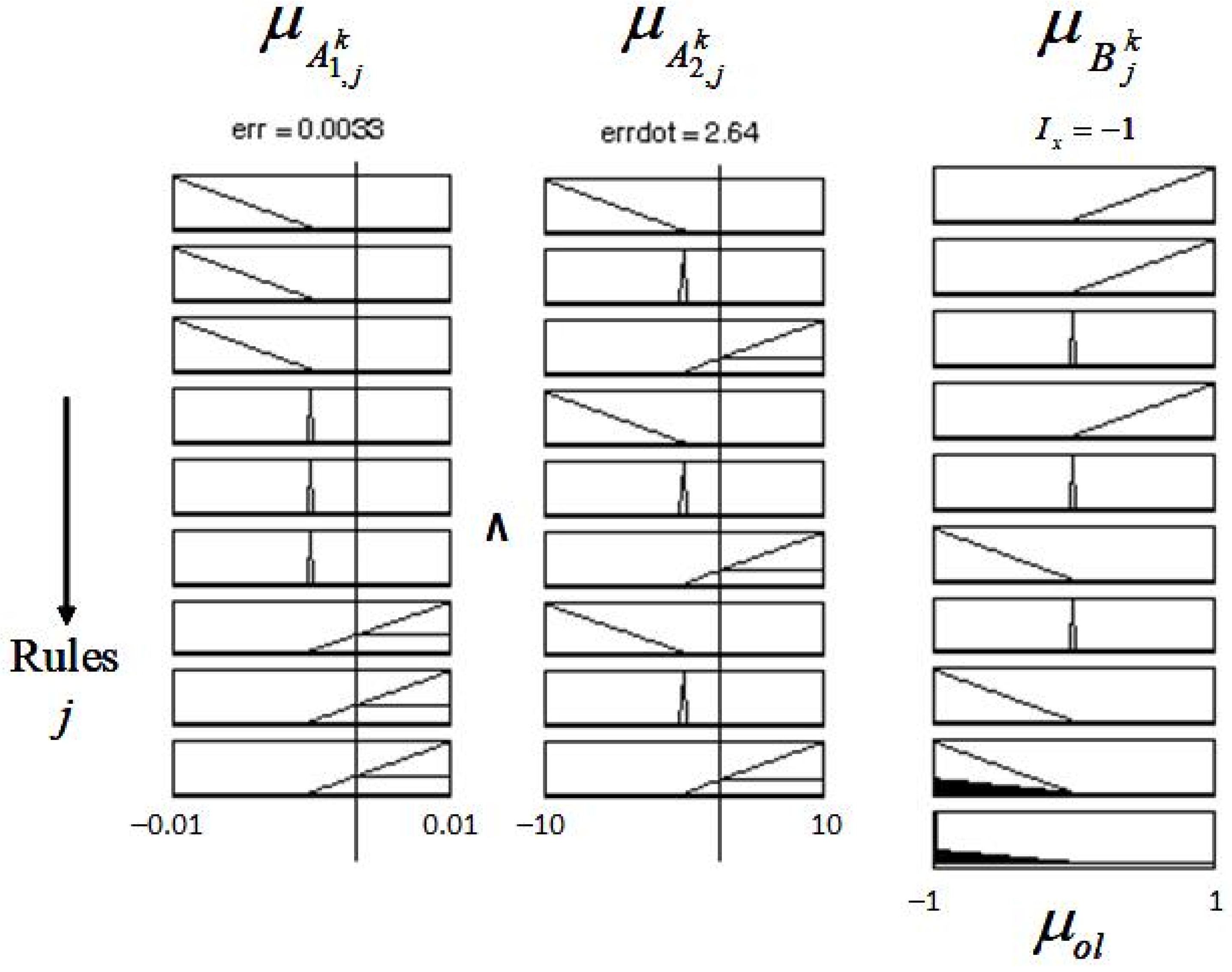
Past numerical and experimental works on the control of magnetic bearings using fuzzy-based and SMC schemes have shown the effectiveness of these schemes in controlling non-linear vibrations in the response of rotors supported by magnetic bearings. These works further showed the superior performance of these control schemes over the conventionally used PID controllers. In an earlier paper [
29], the authors have shown the effectiveness of a fuzzy bang-bang relay controller (FBBRC) for the control of a single-axis active magnetic-bearing system. A two-level bang-bang crisp output is directly produced by the FBBRC. Consequently, it does not need further saturation or any hard-limiting devices. This output is based on the largest of maxima (LOM) defuzzification method. This controller is also structurally simple since its fuzzy output set and rule matrix need only two membership functions. The present paper numerically examines the effectiveness of the same controller for the control of vibration of a rigid rotor supported by two-axes active magnetic bearings. The mathematical model of the nonlinear magnetic-bearing forces considers the coil current and air gap relationship, as well as the cross-coupling due to the geometry of the magnetic bearing. The performance of the FBBRC is compared with the conventional fuzzy logic controller (FLC) and the linear PD controller for controlling the vibration of the rotor-bearing system, particularly, for severe operations due to large rotor unbalance force and high rotor angular speed.
The subsequent sections of this paper are organized as follows.
Section 2 presents the formulation of the governing equations of the rigid rotor-magnetic-bearing system. The design of the fuzzy controller is described in
Section 3. Results of the numerical simulation are presented and discussed in
Section 4. Finally,
Section 5 presents the conclusions.
2. Governing Equations of the Rotor-Bearing System
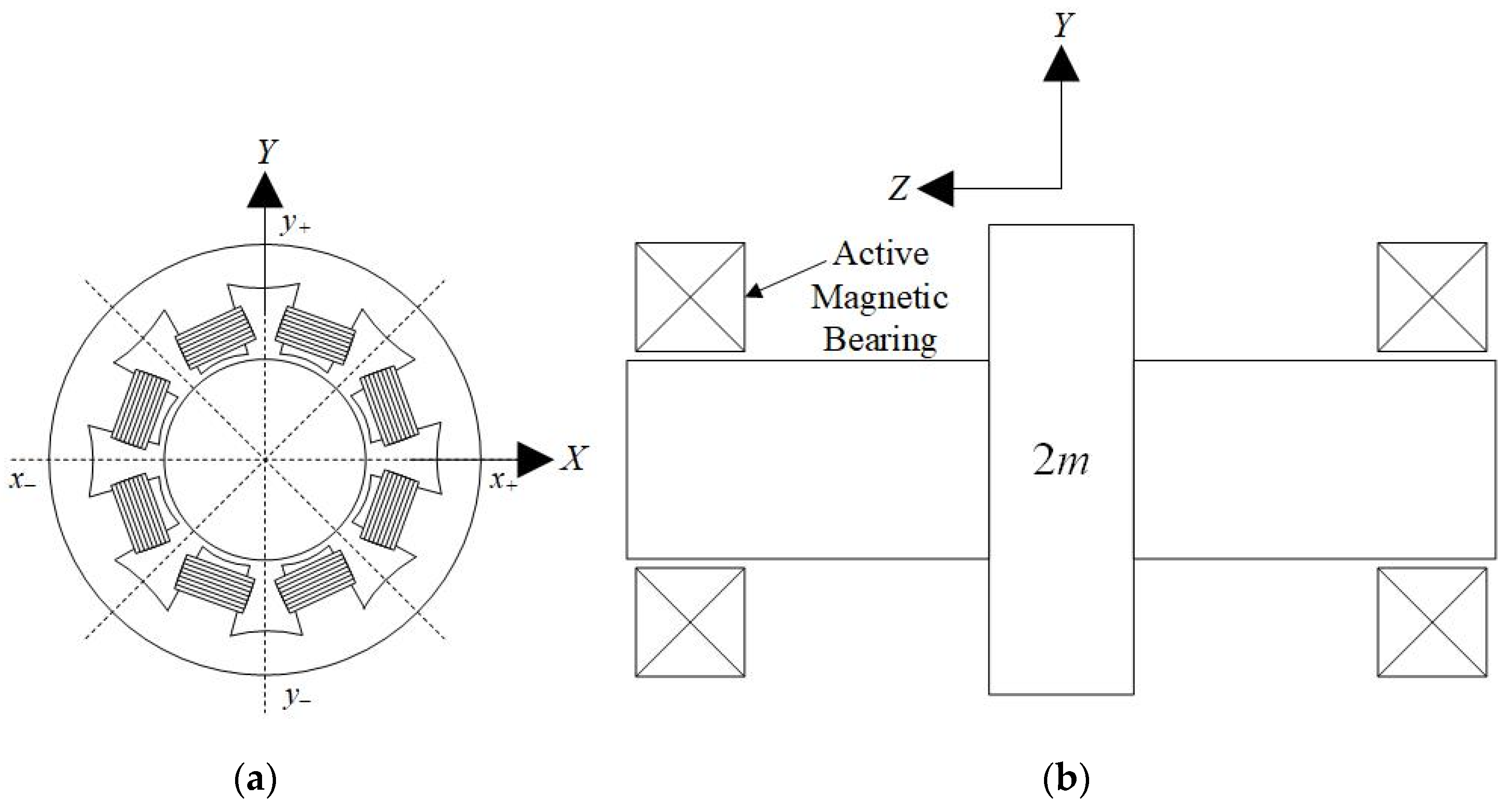
Several assumptions were made in the derivation of the equations of motion for the rigid rotor mounted on active magnetic bearings: (i) the rotor is symmetric, (ii) the rotor unbalance is static and located at the middle of the bearing span, (iii) the axial motion of the rotor and gyroscopic effect are neglected, (iv) the magnetic flux leakage and fringing effect are neglected, and (v) the operation of the magnetic iron is below the level of saturation.
Figure 1 shows the schematics of an active magnetic bearing and a rigid rotor supported by two active magnetic bearings. The coordinates,
X and
Y, represent the directions perpendicular to the rotor’s axis of rotation. The coordinate,
Z, on the other hand, is along the direction of the rotor’s axis of rotation. The displacement of the geometric center of the rotor in the
X and
Y directions are represented by
x and
y, respectively. The equations of motion of the rotor’s geometric center, accounting for the magnetic-bearing forces, rotor unbalance force, and gravity, are given by [
30].
The rotor’s half-mass is denoted by , the eccentricity of the rotor’s center of mass is denoted by , the rotor’s angular speed is denoted by , and the gravity constant is represented by . The magnetic bearing forces in the and directions are respectively represented by and .
The electromagnetic force,
F, generated by a single-acting magnetic actuator is presented in Equation (2). The permeability of free space is denoted by
, the number of magnetic actuator coil turns is denoted by
N, and the area of one magnetic pole is represented by
. The coil current and the length of one air gap are respectively denoted by
and
[
31].
In the operation of these bearings, the differential driving mode configuration is utilized, where a pair of actuators are arranged to counteract each other thus enabling the generation of positive and negative forces. This arrangement requires the bias flux, , and the perturbation flux, , which are respectivley induced by the bias steady-state current, , and the control current, , in the coil. The superposition of and yields the total flux. The maximum dynamic range of the magnetic actuator is obtained by setting to about half the saturation current, with one actuator driven by () and the other by ().
The details on the derivation of the magnetic-bearing forces in the
and
directions for the differential-driving-mode configuration of the magnetic actuators can be found in [
32]. For a nominal air gap,
, the current in the decreasing air gap side, (
), is (
) for the magnetic force in the
direction, and the current in the increasing air gap side, (
), is (
). Substituting these values into Equation (2) yields the nonlinear magnetic-bearing forces for the differential-driving-mode configuration, where the positive and negative forces in the
direction are respectively denoted by
and
The positive and negative forces in the
direction,
and
, can be similarly derived to yield Equation (4).
Accounting for the effect of the geometrical coordinate coupling,
, which couples the governing equations in the
and
directions, the magnetic-bearing forces in both these directions can be expressed by Equation (5) [
29]. The geometrical curvature of the magnetic pole causes the air gap to vary over the entire pole area, and this, in turn, results in the occurrence of a normal force, which is 90 degrees away from the principal force during motion in the principal axis. The ratio of the principal force to the normal force is known as the geometrical coordinate coupling,
[
33].
Inserting Equation (5) into Equation (1) gives the governing equation of a rigid rotor supported by active magnetic bearings.
The proportional,
, and derivative,
, feedback gains for a linear PD controller are related to
,
,
,
,
and
by Equation (7) [
32]. The present work makes use of the system parameters presented by Delprete et al. [
34]. These values are reproduced in
Table 1. The geometrical coupling coordinate, which was not considered in [
34], has a value of 0.2. This value was selected based on the work of Knight et al. [
35], who had presented a range of geometrical coupling coordinate values between 0.05 to 0.25.
4. Numerical Results and Discussion
Numerical simulations were performed using MATLAB and Simulink Release 2021b (The MathWorks, Inc., Natick, MA, USA) computer package to determine the strengths and drawbacks of the three controllers, PD, FLC, and FBBRC, when used to control the vibration of the rotor-bearing system. The values of the parameters used in these simulations are given in
Table 1. For the control of the rotor-bearing system using the linear PD scheme, the fuzzy controller blocks were replaced by PD controller blocks. Since the magnetic bearing has a nominal air gap of 0.50 mm, numerical simulations were terminated when the displacements,
x or
y, reached this value, and the simulations were reported to have failed. The simulations were run for a duration equal to 1500 cycles of the rotor’s motion based on the angular speed,
, and the time increment was chosen to be 0.001 s.
In the first set of simulations, the initial conditions were chosen to be the same along both axes, i.e., , and . The system was then simulated for different values of angular speed and eccentricity of the rotor center of mass chosen over the range 50 to 500 rad/s in steps of 50, and 0.03 to 0.08 mm in steps of 0.01, respectively. It was found that none of the controllers was able to bring the rotor to its equilibrium position () when ( mm). In other words, the simulation failed with or having exceeded 0.50 mm sometime during the simulation. For mm, the PD controller failed for all combinations of (,) while the FLC failed for all combinations of (,) except 50 rad/s, 0.03, 0.04 mm. However, the FBBRC gave better results with the simulations being successful for 50, 100 rad/s and all , for 150 rad/s, 0.03, 0.04, 0.05, 0.06 mm, and for 200 rad/s, 0.03 mm.
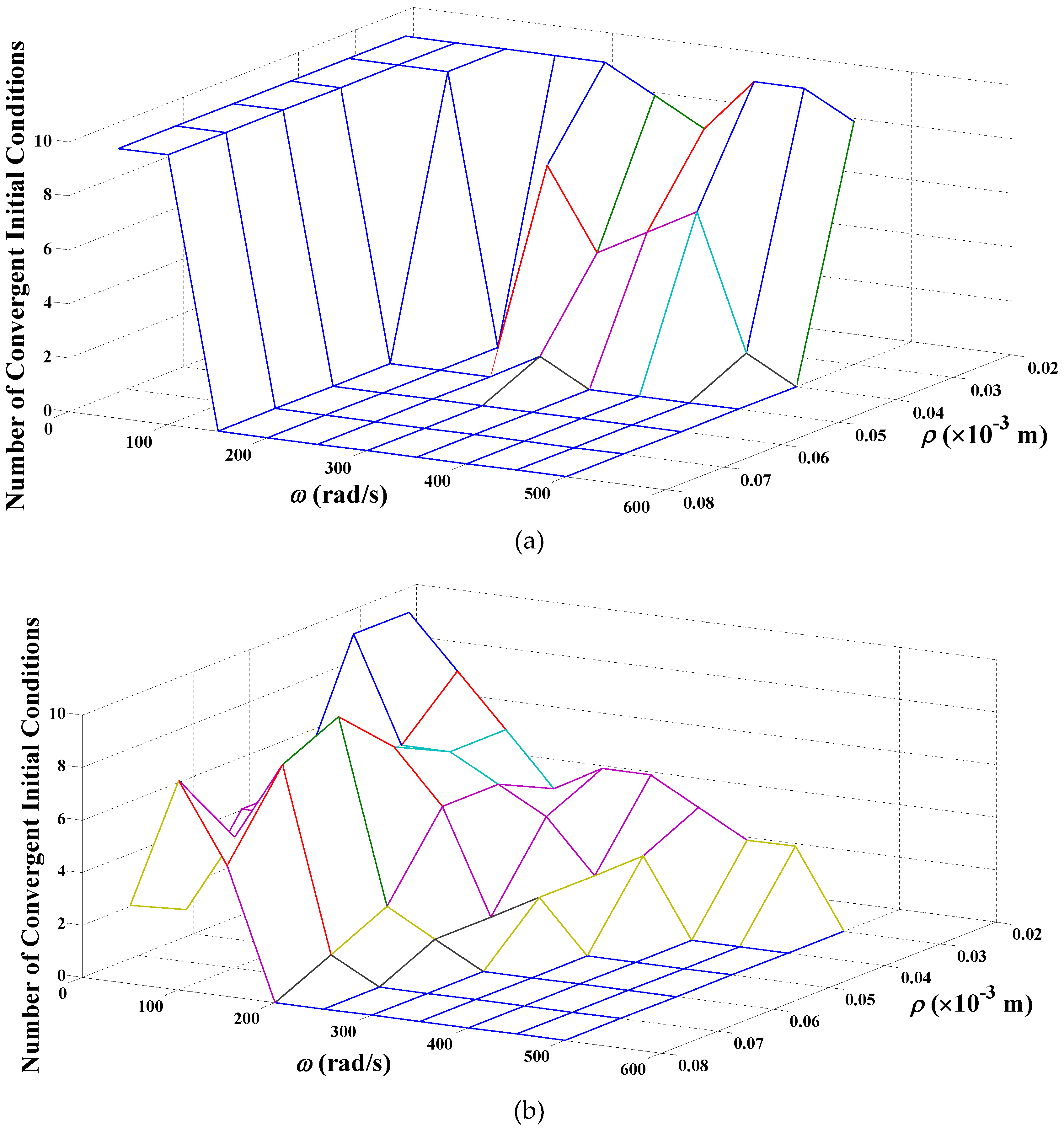
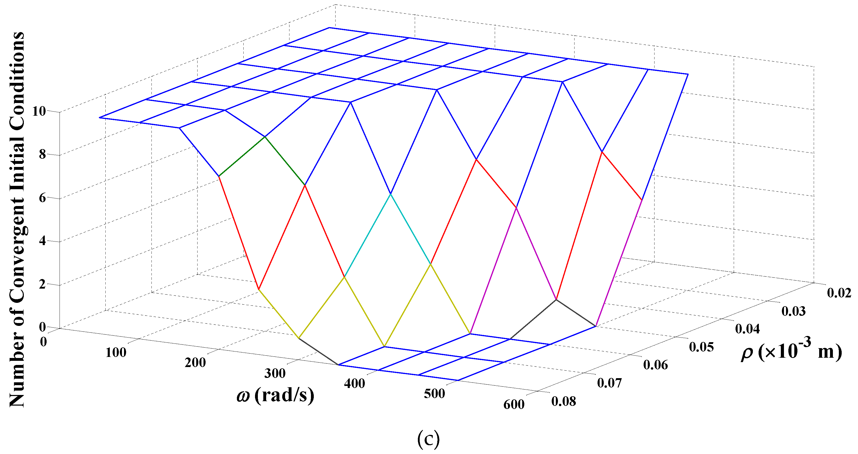
The response of the rotor-bearing system for
mm and with the above values of
and
is shown in
Figure 6. A value of 10 along the vertical axis implies that the system simulation for all 10 values of initial conditions is successful. We refer to this value as the number of convergent (initial) conditions. A value less than 10 implies that the simulation fails for one of the initial conditions. It can be seen from
Figure 6a that the presence of the PD controller improves the system performance for all initial conditions when
is small (50 and 100 rad/s). The presence of the FLC controller makes the system behavior erratic with simulations being successful only for small
(50 rad/s) and small
(0.03 and 0.04 mm),
Figure 6b. The FBBRC controller gives superior performance for a larger range of (
,
) pairs, as can be seen from the flat region at the top of
Figure 6c.
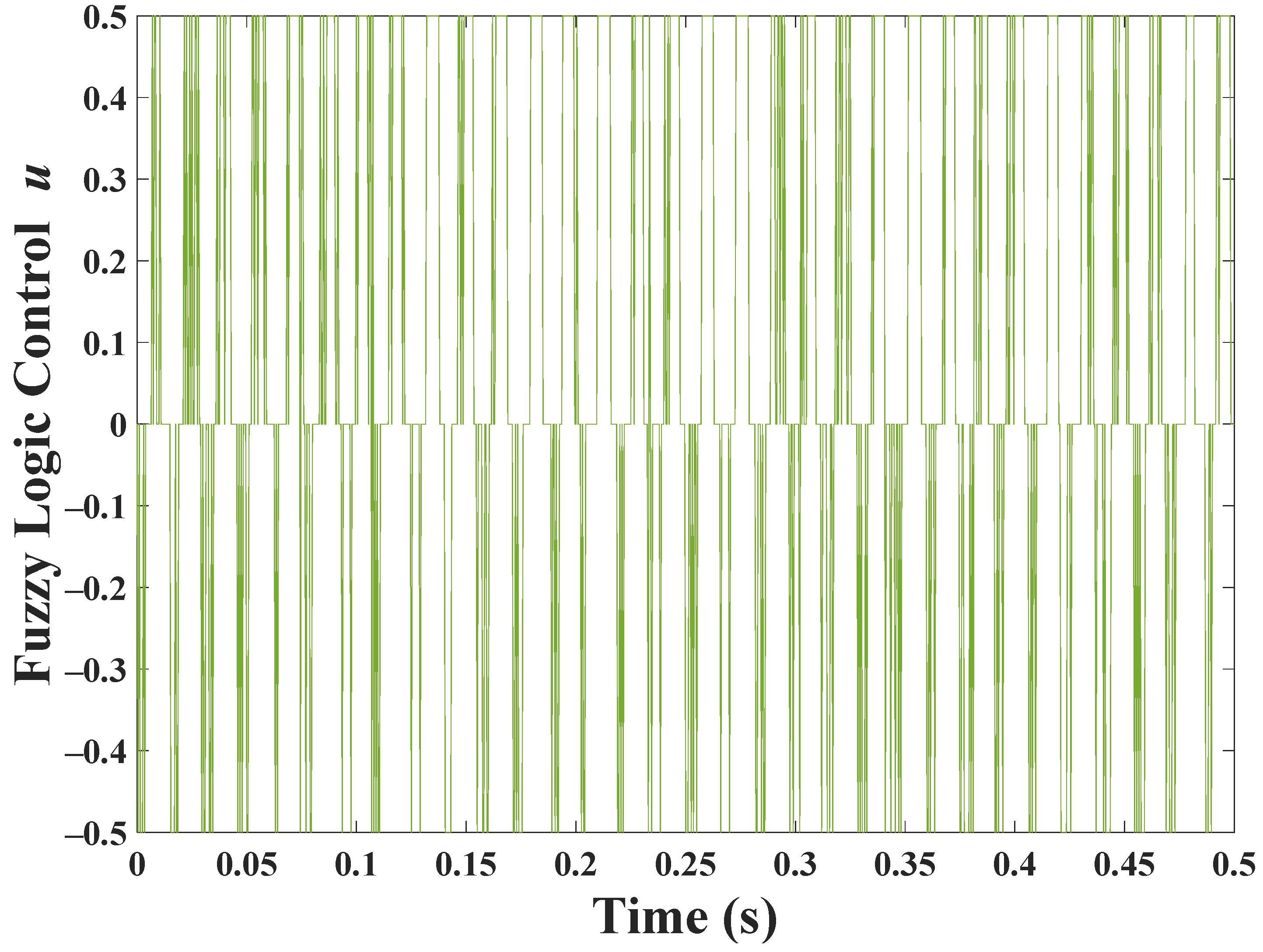
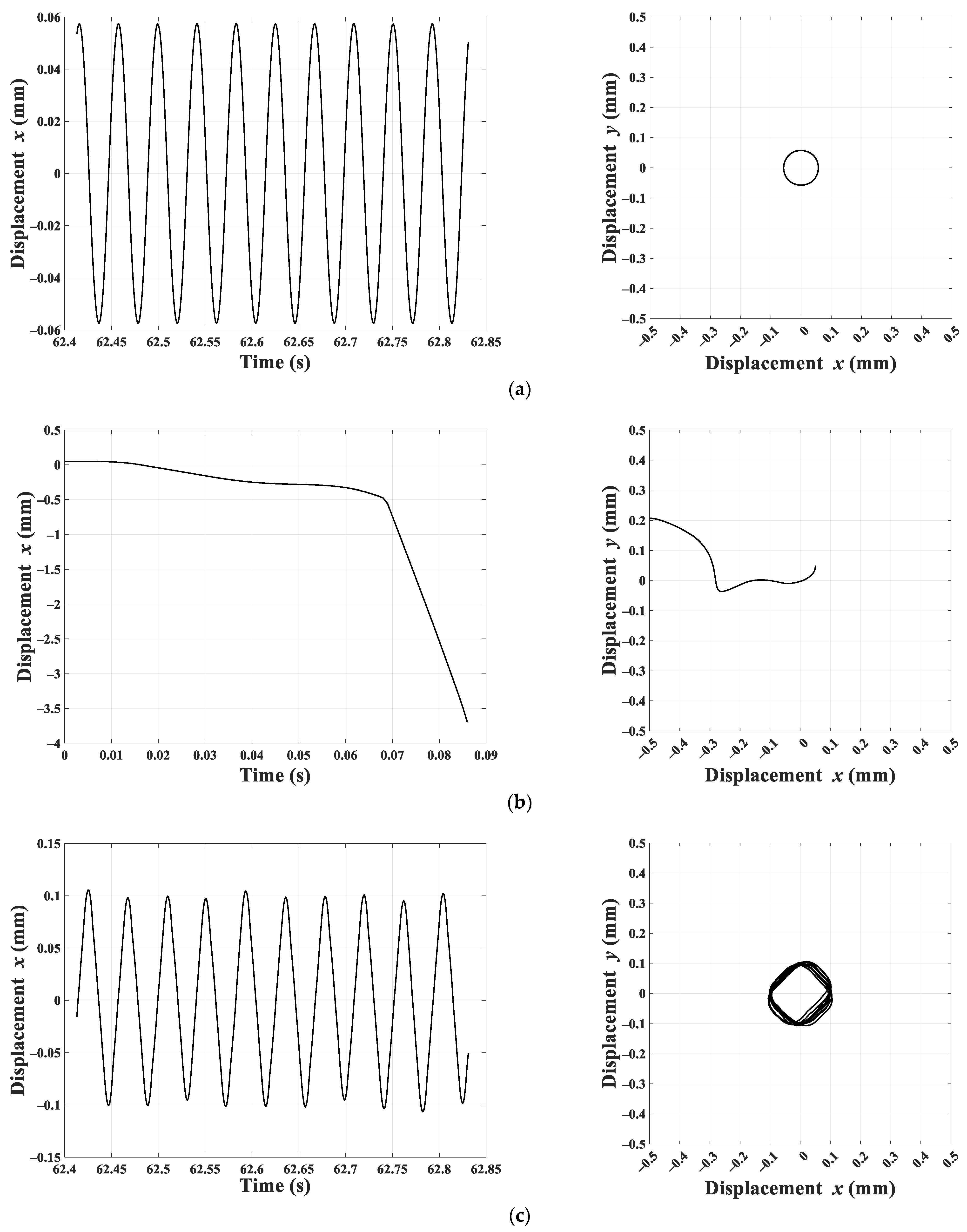
Figure 7 and
Figure 8 show the last 10 cycles of the system responses for two different (
,
) pairs and
mm. These responses are typical for initial conditions,
, that were simulated. The left column shows the time response for
(time response for
is similar), and the right column shows the rotor response on the
plane. The
plane axes have been intentionally selected to represent the air gap length of 0.50 mm.
Figure 7 shows successful simulations when a PD controller or an FBBRC controller is used. The FLC controller fails for this case. Note that the response to a PD controller contains a single frequency, and hence, the rotor position makes a perfect circle. However, the response due to the FBBRC contains multiple frequencies, and hence, the rotor response forms a non-uniform shape.
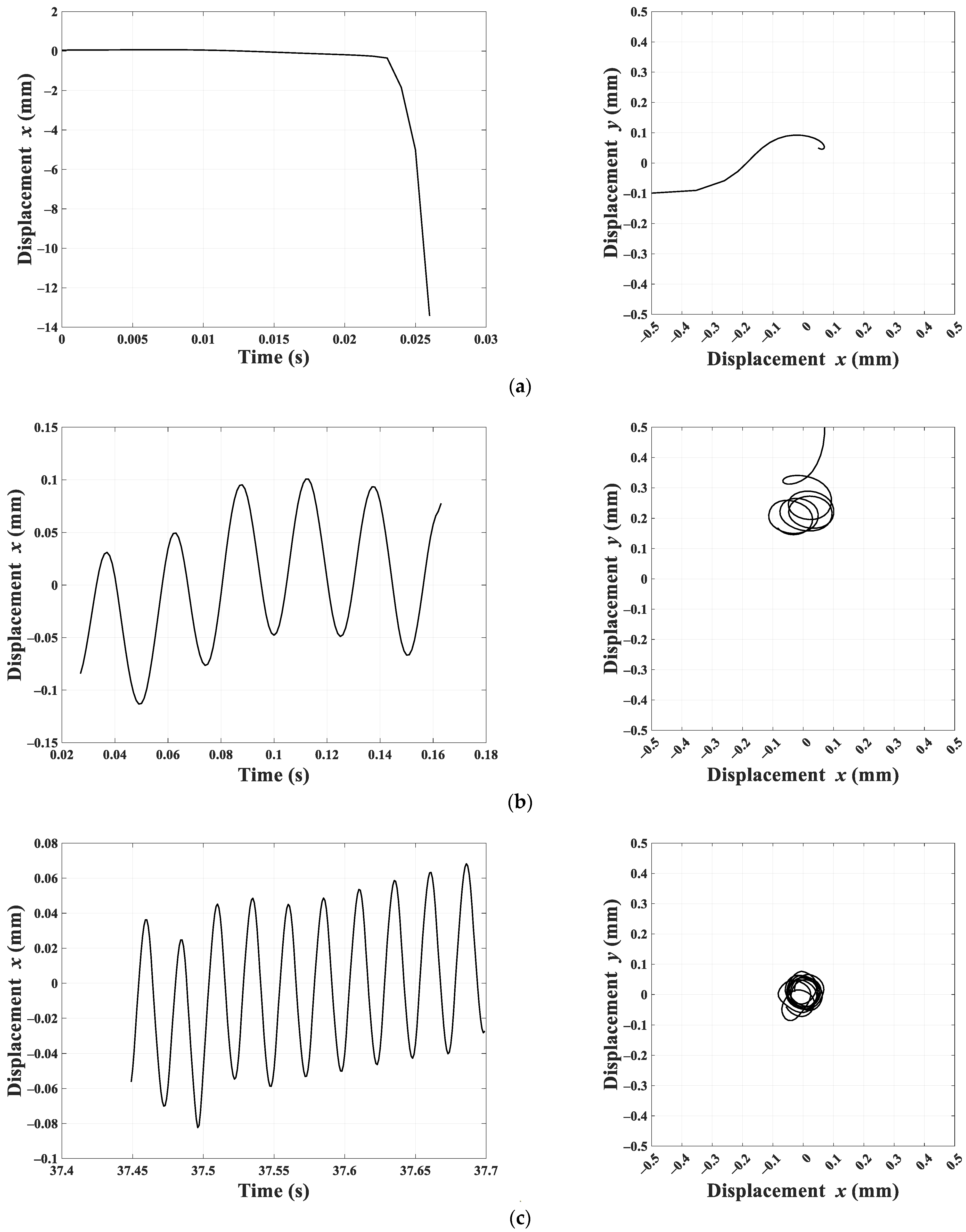
Figure 8 shows the same responses for higher
and
values. Here, both the PD controller and FLC responses failed while the FBBRC produced a bounded response, albeit with a non-uniform rotor response.
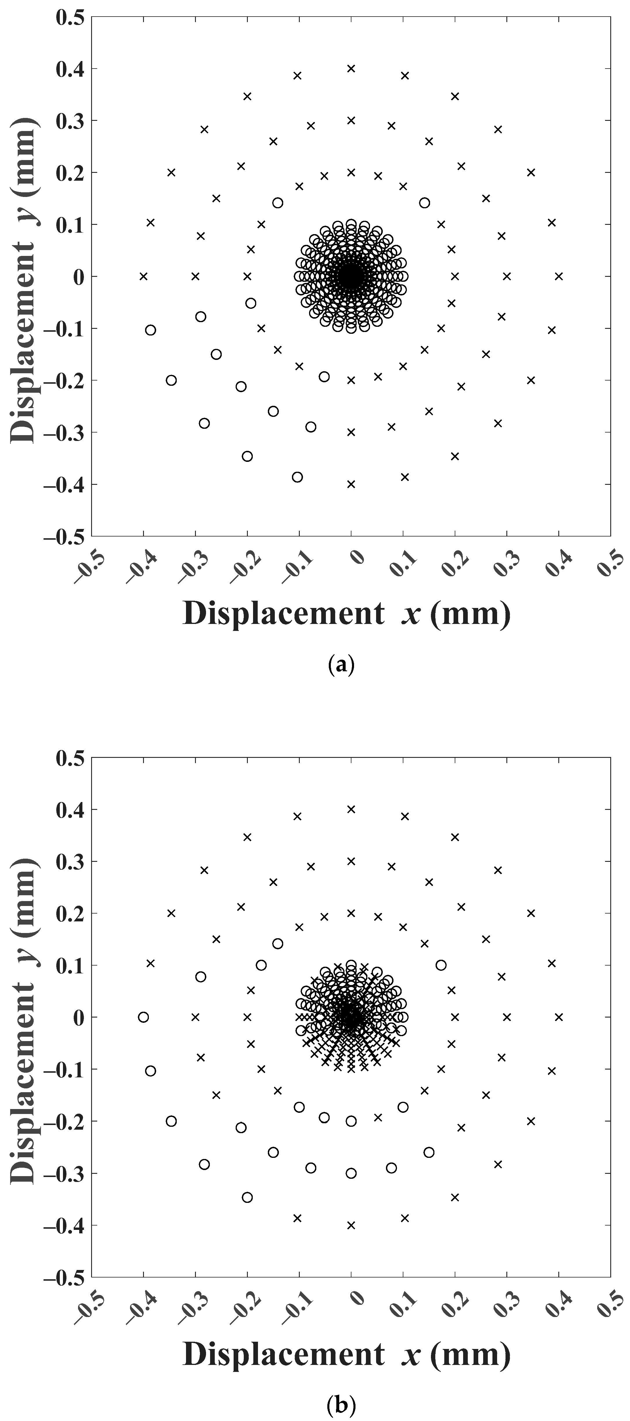
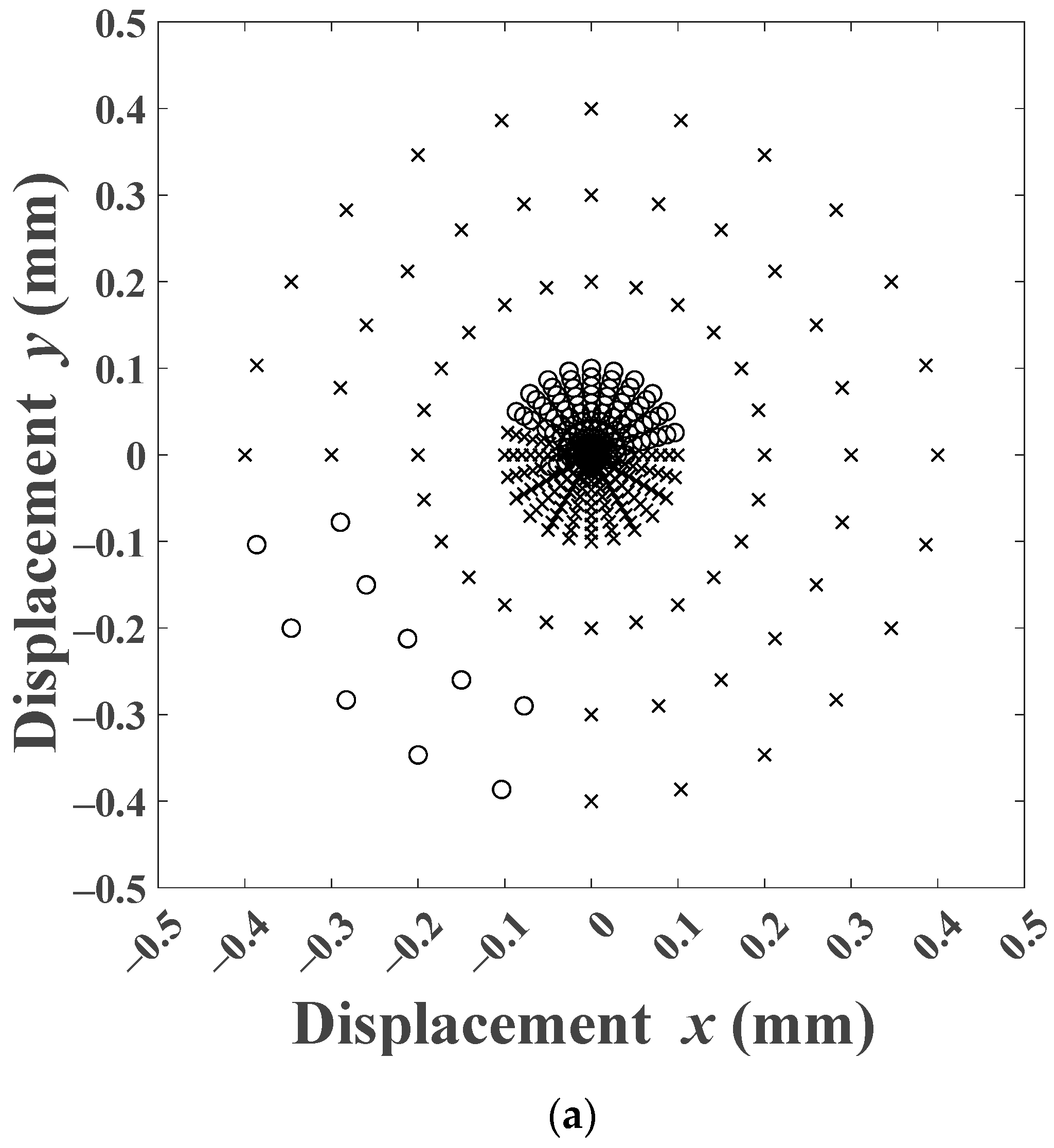
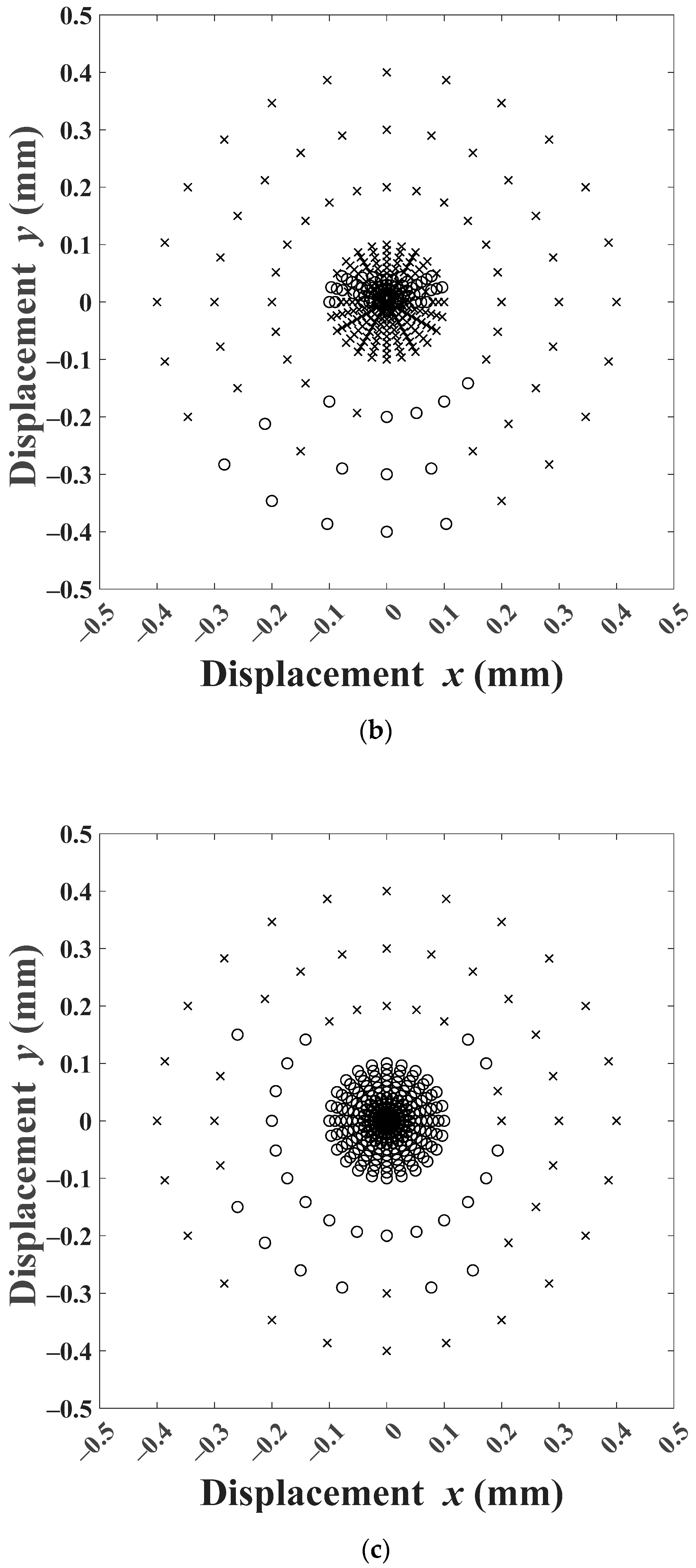
Figure 9 and
Figure 10 simulate the system for a fixed (
,
) pair but different initial displacements. The marks on the graph show the initial positions of the rotor (
,
) for which the system was simulated. The ‘×’ represents a simulation that failed, while an ‘o’ represents a successful simulation. The initial positions were chosen on radial circles with the equilibrium point (
) as the center, and radii 0.01 to 0.10 mm in steps of 0.01 mm and 0.20, 0.30, 0.40 mm. Angular increment with 15° step totaling 24 points was chosen on each circle. As expected, the simulations failed for large initial displacements in most cases for all three controllers. For
0.08 mm and
100 rad/s,
Figure 9, the PD controller response was successful for all initial displacements up to 0.10 mm. The behavior of the FLC controller was, as seen earlier, erratic with the ‘×’ and ‘o’ not showing any discernable pattern. The FBBRC showed better performance with successful simulations up to 0.20 mm. For
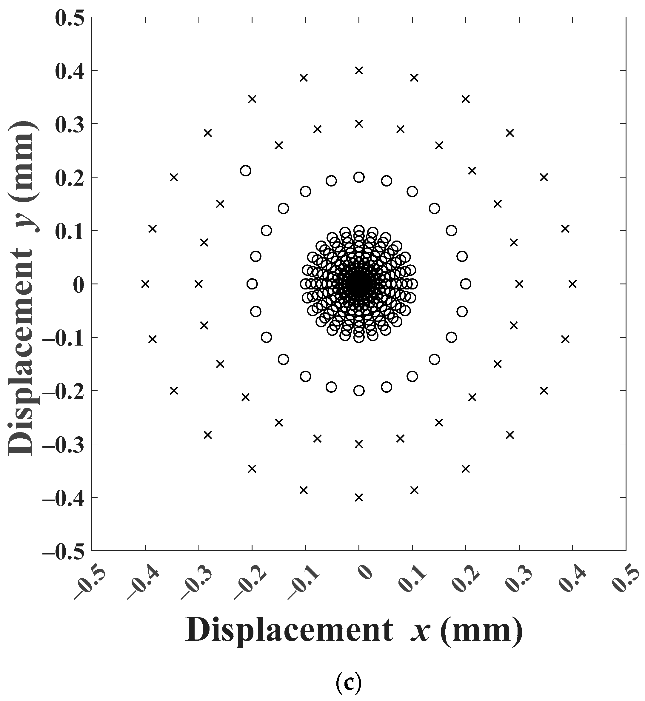
0.06 mm and
250 rad/s,
Figure 10, the PD controller response showed an interesting pattern. The simulation was successful for initial displacements up to 0.10 mm only in the first quadrant and part of the second quadrant. The erratic behavior of the FLC responses did not come as a surprise. However, the FBBRC showed a truly superior behavior with the responses being successful for all initial displacements up to 0.10 mm, most initial displacements of 0.20 mm, and a few initial displacements of 0.30 mm.
It is noted that the robustness of the proposed FBBRC was not addressed in the present work. The robustness of the proposed bang-bang control scheme to external disturbances and variations of the rigid rotor-magnetic-bearing system parameters can be achieved with the introduction of SMC to the control scheme. SMC offers the most well-known robust strategy, which works under discontinuous on/off (bang-bang) operation [
39]. This controller can handle external disturbances and variations in the system parameters to give robust performance. To obtain time-optimal control, the SMC directs the control activity through bang-bang controllers, which are entrusted for minimum time response. This robust and minimum time property of the control scheme for the rigid rotor-magnetic-bearing system can be achieved with the combination of SMC and bang-bang controller.


