Article

Study on Influencing Factors of Temperature Variation Displacement Compensation Behavior of Gas Insulated Switchgear Shell Bellows

1
Guangdong Power Grid Company, Guangzhou Electric Power Bureau, Guangzhou 511400, China
2
Department of Electrical Engineering, Tongji University, Shanghai 200092, China
3
State Grid Shanghai Pudong Electric Power Supply Company, Shanghai 200122, China
*
Author to whom correspondence should be addressed.
Energies 2022, 15(11), 3954; https://doi.org/10.3390/en15113954
Submission received: 12 April 2022 / Revised: 15 May 2022 / Accepted: 23 May 2022 / Published: 27 May 2022
(This article belongs to the Section F6: High Voltage)

Abstract

:
Bellows are the key structures that compensate for and absorb the temperature-dependent displacement of a gas insulated switchgear (GIS) shell. It is of great engineering value to master the relationship between the temperature-dependent displacement behavior and various influencing factors. Based on the analysis of the influencing factors of the temperature variation displacement compensation ability of the GIS bellows, a bellows model was established. By coupling it with a shell having different degrees of bending through two layout methods, finite element simulation was carried out based on ABAQUS software to obtain the regular relationship between the temperature variation displacement compensation behavior of the bellows and various influencing factors. The results of the case study show that the temperature change displacement compensation ability of the bellows is most significantly affected by their own structural size. Reducing the wall thickness and increasing the wave height of the bellows can effectively improve the temperature change displacement compensation ability of the bellows and reduce the stress concentration in the compensation process. The change in the GIS shell shape is the second-most important influence; when the sliding support base of the bus barrel is lower than the fixed support base, the amount of temperature change displacement compensation of the bellows increases and the compensation capacity decreases, and, on the contrary, the temperature compensation capacity increases. Within the operating temperature range, the compensation ability of bellows with a distributed arrangement is better than that of a centralized arrangement, and can alleviate the initial deformation caused by gravity and gas pressure in GIS equipment.

1. Introduction

The gas insulated switchgear (GIS) needs to bear a wide range of temperature fluctuations during operation, and the shell span is large, so the resulting temperature variation displacement is mainly compensated for by the bellows. Accidents such as inclined cylinder support and gas leakage of GIS equipment occur from time to time due to unreasonable bellows configuration [1,2,3]. Furthermore, the Anti-Accident Measures for Expansion joint of Outdoor GIS Equipment of State Grid Corporation of China, compiled and issued by the Operation Inspection Department of State Grid, notes that, at present, outdoor GIS equipment suffers from a number of problems, such as unreasonable bellows selection, insufficient consideration of the impact of thermal expansion and cold contraction, and errors in on-site installation [4]. Therefore, it is of great engineering value to master the regular relationship between the temperature compensation capacity of bellows and various influencing factors, to ensure that the bellows can effectively and fully absorb the temperature variation displacement of the compensation shell, and to provide a theoretical basis and guidance for the design, maintenance, and replacement of bellows.
The fundamental reason for the difference in bellows’ temperature compensation ability lies in their different mechanical properties. A literature search shows that the research on the influence of mechanical properties of bellows in engineering application has gradually attracted the attention of scholars at home and abroad. For example, Fang H et al., used ABAQUS to analyze the factors affecting the mechanical properties of embedded bellows, and verified the validity of the simulation results through full-scale tests [5]; You Q et al., used the method of combining parameter analysis and finite element numerical simulation for the stress and deformation calculation of steel bellows [6]; and Wei K et al., calculated the bending stiffness of carbon fiber bellows under different loads using the finite element method. The results showed that the relationship between the bending stiffness and loads was non-linear [7]. Fang H et al., conducted finite element simulation of double wall bellows, and the results showed that the local stress and strain of bellows increase due to creep [8]; Sellappan A et al., concluded that the characteristics of long stroke and high speed created higher requirements for the design of bellows [9]; Hong L et al., conducted fluid–structure coupling simulation analysis of the U-shaped bellows and pointed out that the equivalent stress depends on the pressure and working speed of the bellows [10]; Chen T et al., studied the relationship between the wall thickness, waveform, curvature, and other factors of three types of bellows, and the local yield load, and modified the yield criterion calculation formula [11]; Zinovieva et al., solved the static problem of bellows and analyzed the stability of different bellows when they were deformed, using the finite element method [12]; Yuan Z et al., pointed out that the ultimate bearing capacity of S-shaped bellows decreases slightly with the increase in shell layers [13]; and Tomarov et al., analyzed the factors affecting the damage of the bellows expansion joint and proposed the establishment of a two-stage failure mechanism of this joint [14].
However, the above research results mostly focus on the simulation calculation or empirical formula fitting of the individual structure of the bellows, and consider less the bellows and other structures of GIS equipment as a whole. Establishing a complete finite element model to more accurately simulate the compression and tension of the bellows under multiple constraints is an important measure to ensure that the simulation results are consistent with the engineering practice. Secondly, under the influence of different layouts and shell shapes, the stress of the bellows differs, which affects their compensation ability for temperature change displacement. Adopting a reasonable layout and ensuring the normal shape of the shell enables bellows with the same structural size to fully utilize the compensation effect of temperature change displacement. However, the existing studies pay less attention to the above two influencing factors.
In view of this, this study proposed an equivalent method to examine the interaction between different structures of GIS equipment, coupled bellows having different structural sizes with other components of GIS equipment, realized finite element simulation for the complete GIS equipment, examined the influence of the structural size of bellows on their temperature variation displacement compensation ability, and compared the difference in bellows’ temperature compensation ability for two different layout modes and different degrees of bending of the cylinder. The action law of the influencing factors of the bellows’ compensation capacity is summarized, which can provide corresponding guidance for the arrangement or replacement of bellows in engineering applications.

2. Influencing Factors of Displacement Compensation Behavior of GIS Shell Bellows

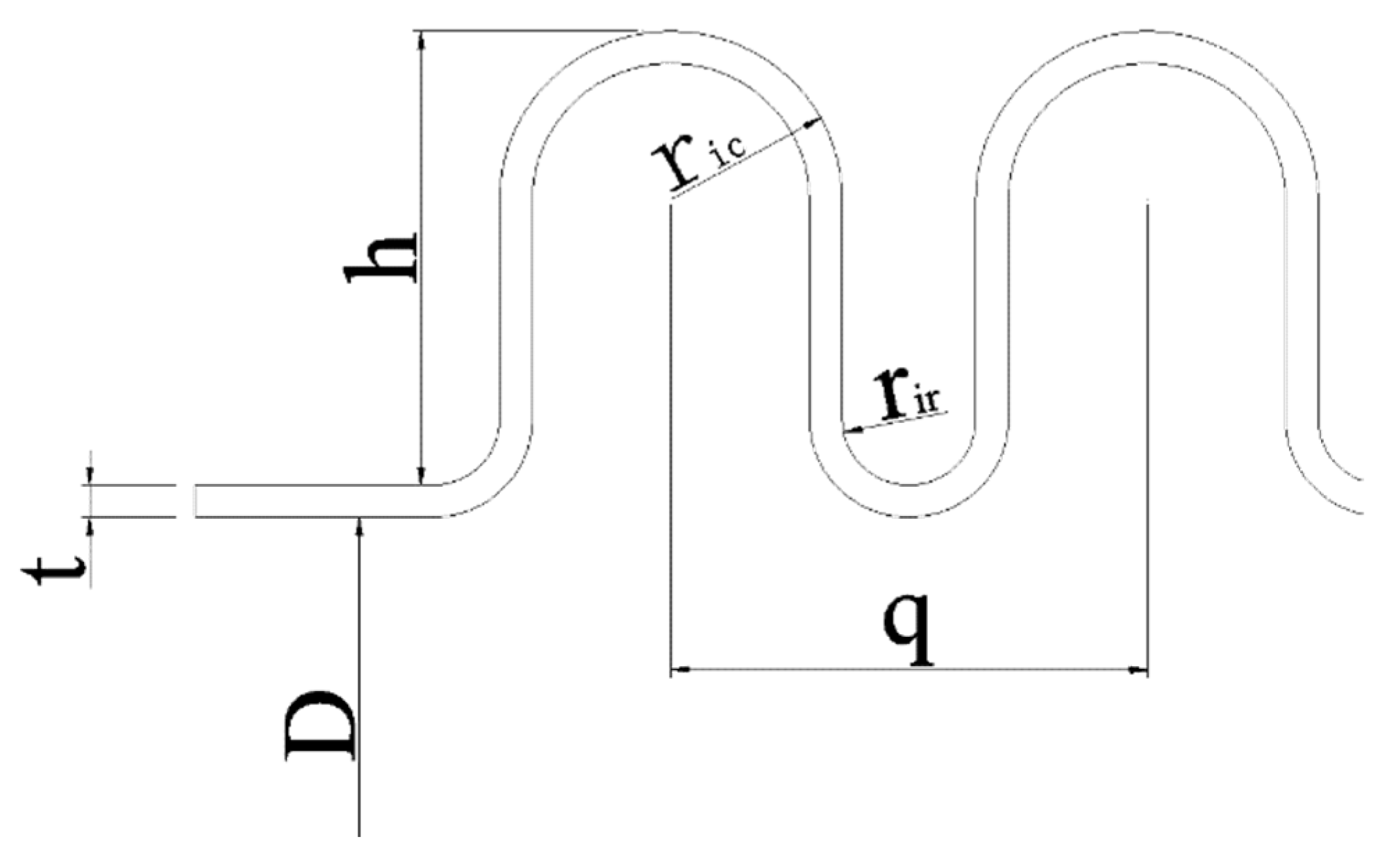
2.1. Structural Dimensions of Shell Bellows

The bellows wave applied in GIS equipment is generally a U-shaped bellows, and the local structure is shown in Figure 1.
According to the design standard of the bellows’ expansion joint and relevant technical standards of the State Grid Corporation for electrical appliances [15,16,17], the design size of the wall thickness is generally within the range of 3 to 30 mm, and is not greater than 5% of the inner diameter. The design size of wave height h should be consistent with Equation (1):
D/3 ≥ hRic + rir
In terms of GIS equipment, it is difficult to greatly increase the wave number of bellows due to the existence of disconnectors, current transformers, and other equipment, in addition to the influence of the overall wiring and outgoing line of the substation. Therefore, wall thickness and wave height have become two key influencing factors. Generally speaking, the smaller the wall thickness and wave height, the stronger the absorption and compensation capacity of the bellows. However, the smaller the axial stiffness and bending stiffness, the smaller the corresponding safety margin; that is, when the temperature fluctuation exceeds the specified working temperature, the greater the risk that the bellows will not work normally [15,16].

2.2. Coaxiality of Shells on Both Sides of Bellows

The shell shape of GIS equipment mainly refers to the bending of the shell axis in the vertical direction, as shown in Figure 2. There are two main reasons for this phenomenon. One is the displacement or deformation of the base due to factors such as foundation settlement, which leads to the bending of the outer shell of the GIS equipment; the other is the problem that the adjacent cylinders are not collinear during the installation and construction of the shell, which is compensated for by the bellows [17].
The bending of the GIS shell in any direction will affect the stress relationship between the sliding support leg and the base, and then affect the coordination between the sliding support leg and the bellows. Finally, it will be intuitively reflected in the temperature compensation ability of the bellows. Specifically, when the cylinder on the sliding support leg side is higher than the cylinder on the fixed support leg side under the influence of the base, the pressure between the lifted part and the base increases under the influence of the bellows, so the bellows needs to overcome greater friction during extension and contraction. When the GIS shell is not collinear due to installation error, the bellows also needs to compensate for the installation error in addition to overcoming greater friction.

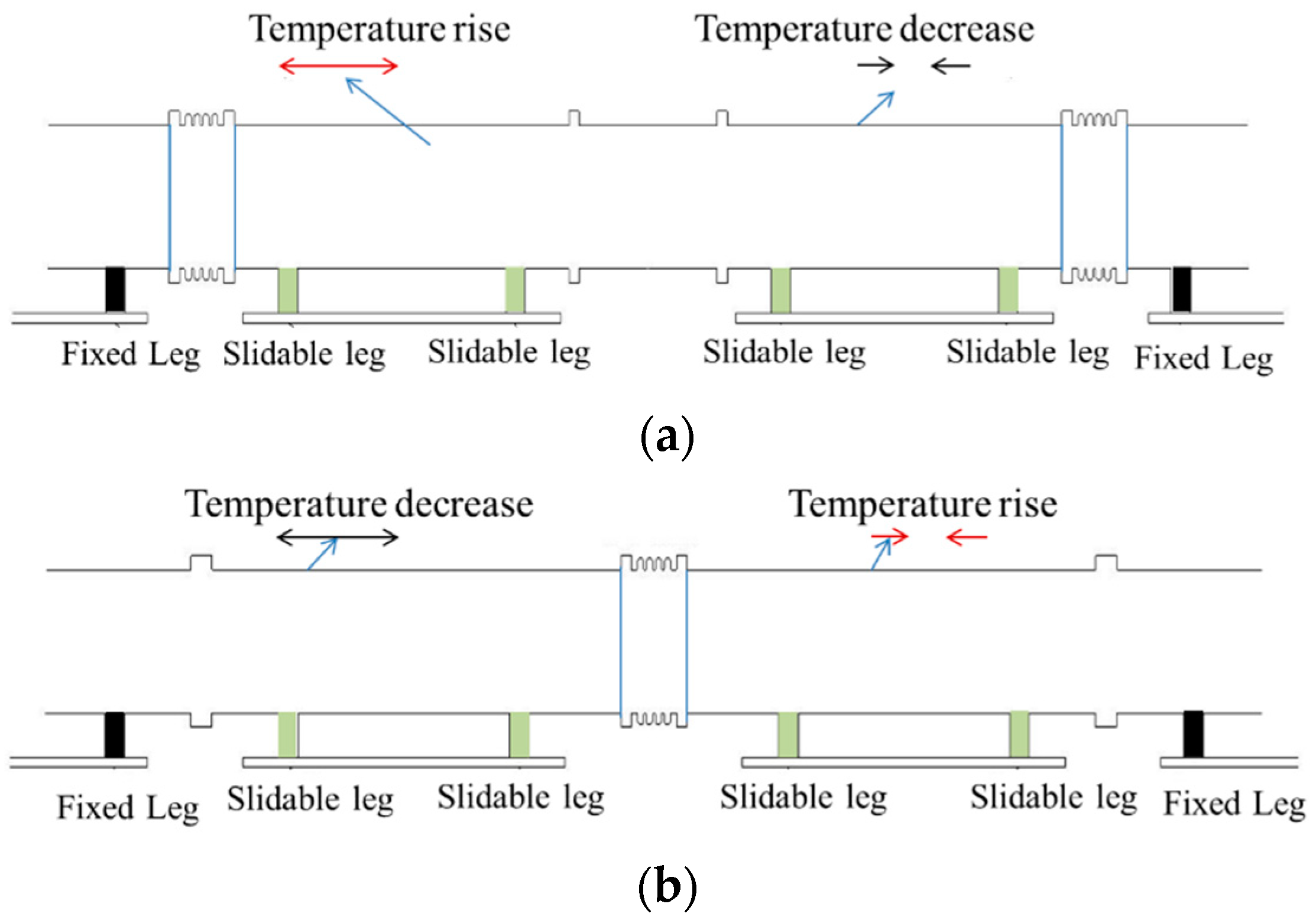
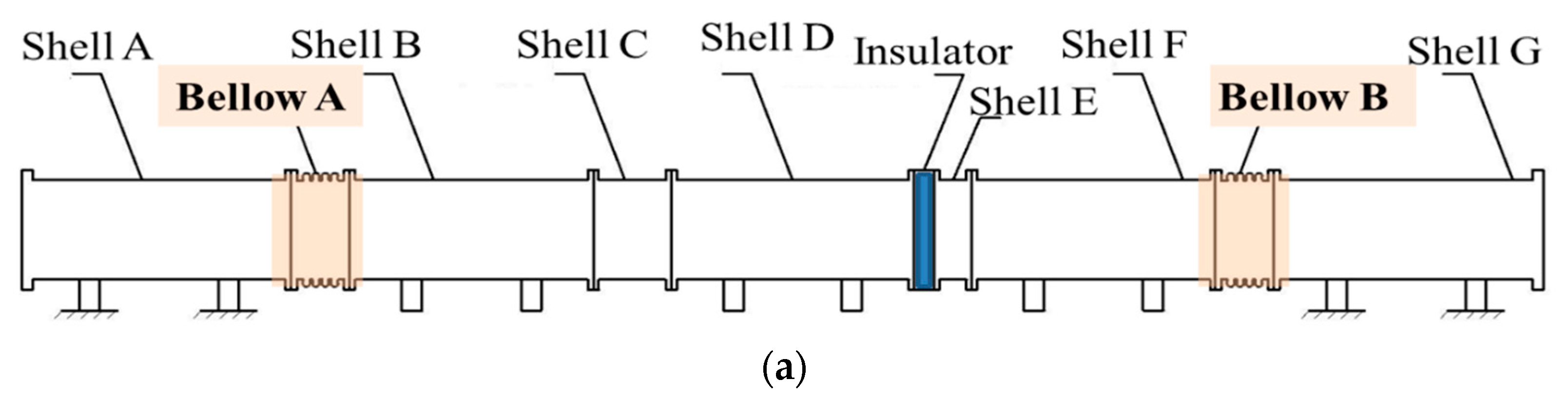
2.3. Arrangement of Shell Bellows

There are generally two support modes in GIS equipment, namely fixed support and sliding support [17]. In the process of fixed support, the sliding displacement of several support legs can be compensated for, so there may be changes in the sliding displacement of several support legs in the process of fixed support. The layout schemes of bellows can be divided into distributed and centralized layouts. In the scheme of the distributed arrangement, one side of the bellows is equipped with fixed support legs as a limit, so that the bellows are mainly compressed or stretched in one direction. In the centralized arrangement scheme, the bellows are installed between a pair of sliding support legs. At this time, the bellows bear compression or tension from two directions [17]. Two equivalent layout modes of GIS bellows are shown in Figure 3.
Due to the different compression and tensile directions of bellows in the two layout schemes, there are some differences in the compression (elongation) and maximum stress of bellows in the same temperature fluctuation range. At the same time, the support legs of most GIS equipment are mainly located below the shell and are in contact with the ground. The support legs of a few GIS devices are located behind the shell and in contact with the wall. Therefore, compared with the side of the bellows close to the support legs, the side further from the support legs is less constrained in the process of compression and elongation, which leads to differences in the amount of compression (elongation) and maximum stress at the upper and lower ends or front and rear ends of the bellows.

3. Simulation Modeling of Shell Bellows’ Displacement Based on ABAQUS Soft

3.1. Simulation Model Establishment and Contact Setting

The structure of GIS equipment is complex and there are many ancillary facilities. However, the ancillary facilities are not rigidly connected with the GIS equipment shell, which does not affect the temperature compensation capacity of the bellows. The reconstruction not only greatly increases the subsequent simulation calculation cost, but is also not conducive to the research on the influencing factors of the temperature compensation capacity of GIS bellows. Therefore, it is necessary to choose various structures when reconstructing the real model. The statistical data of fault cases show that the frequency of temperature change faults of the support leg, shell, and basin insulator in GIS equipment is significantly higher than that of other structures. Therefore, the simulation model should be able to truthfully reflect the coupling relationship between key structures, such as the support leg, shell, and basin insulator and bellows.
The shell body, bellows, and basin insulator in physical GIS equipment are fixed by bolts, and the thermal expansion and cold contraction of bolts can be ignored compared with the shell body. Therefore, only the shell body, bellows, and basin insulator having a flange structure needed to be established here. Then, the binding contact in finite element software was used for simulation; that is, the corresponding nodes are no longer separated in the whole analysis process. Since the shell body and support leg are fixed by welding, it was only necessary to combine the shell body and support leg into a solid model through a Boolean operation during modeling, which is regarded as a rigid connection. Regardless of whether the GIS equipment adopts sliding support or fixed support, the support leg and the foundation base could be unified into the same structure during modeling, and simulated through different contact attributes in the finite element software. The lower surface of the fixed support leg and the upper surface of the foundation base were also constrained by the binding contact. The lower surface of the sliding support leg and the upper surface of the foundation base were simulated using the finite sliding contact, which can reflect the friction coefficient between them.
Due to the symmetry of the structure of GIS equipment, one side of the central symmetry plane could be selected to establish a finite element model to reduce the amount of simulation calculation. Then, different connection modes were simulated through the contact setting in the finite element software, ABAQUS. Binding constraints were established between the upper surface of the base and the lower surface of the fixed support leg, and between the bellows and the shell, to simulate the fixed support and rigid connection. Contact attributes that reflect the friction between metals were established between the upper surface of the base and the lower surface of the sliding support leg to simulate the sliding support.
The case simulation model in this paper refers to the 220 kV GIS equipment of a substation, including six sections of shell, two bellows, a basin insulator, four fixed support legs, and eight sliding support legs. The actual layout is shown in Figure 4, and the corresponding axial dimensions are shown in Table 1.
Comprehensively considering the mechanical and insulation requirements of GIS equipment [18,19], the control group model was established according to the more generic and common bellows’ structural dimensions of 220 kV GIS equipment; that is, the outer diameter of the straight side section is 400 mm, the wall thickness is 15 mm, and the wave height is 60 mm. Then, combined with the discussion on the structural dimensions of bellows in Section 2, the bellows’ wall thickness was reduced and increased by 4 mm, and the wave height was reduced and increased by 5 mm, respectively, on the basis of the control group model. The experimental group model was established and coupled with other structures of GIS shells according to two different layout modes. For the convenience of the following description, the corresponding finite element model is referred to in the form of A_B_C. When A is 1, it indicates a centralized layout, and when A is 2, it indicates a distributed layout; B indicates the wall thickness of the bellows; and C indicates the wave height of the bellows; for example, 2_15_55 and 1_11_60 refer to distributed layout bellows with wall thickness of 15 mm and wave height of 55 mm, and centralized layout bellows with wall thickness of 11 mm and wave height of 60 mm, respectively.

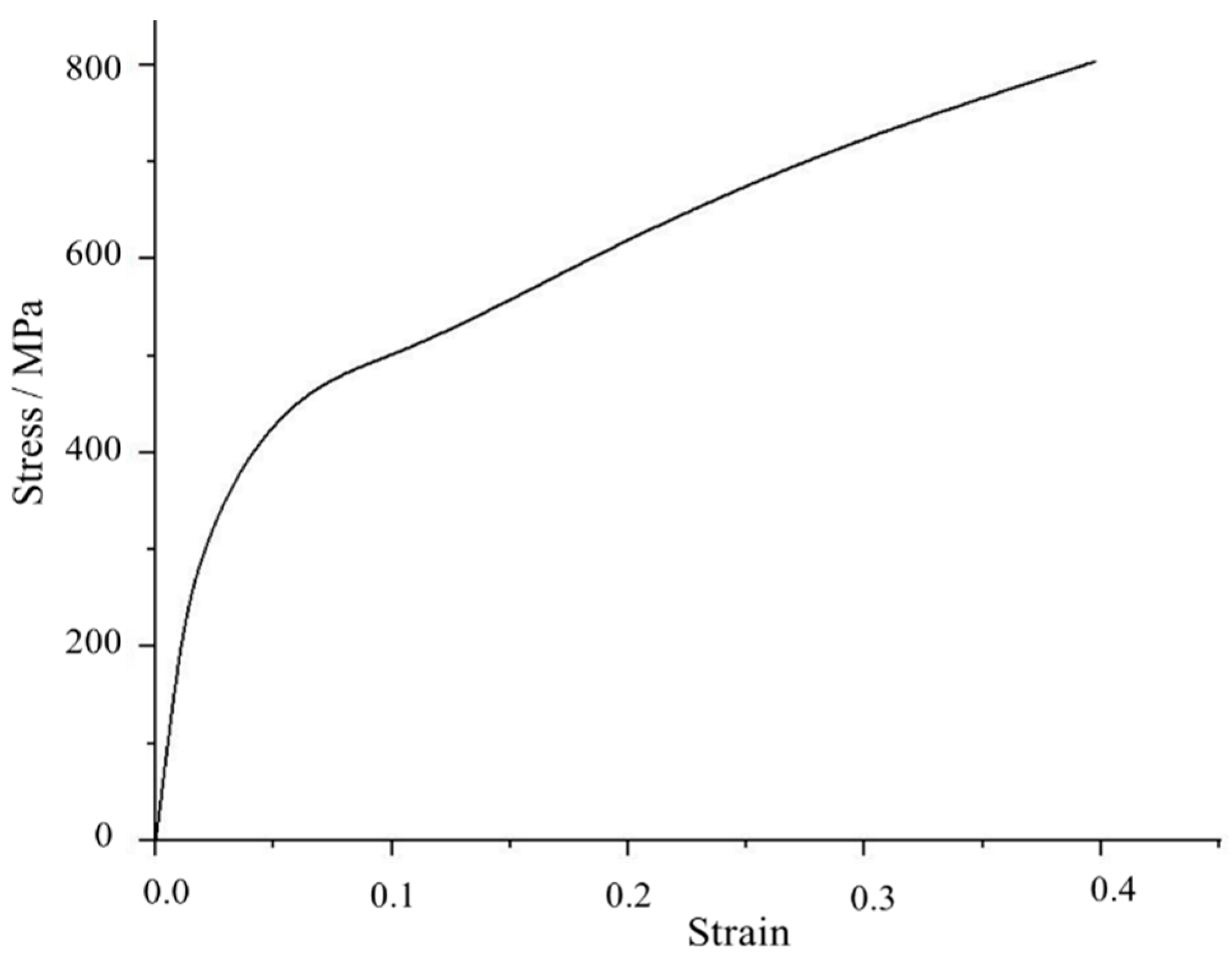
3.2. Material Property Settings

Since this study mainly investigated the bellows structure of GIS equipment, the material properties of other structures, such as the shell, support leg, and basin insulator, could reflect the basic constitutive relationship in the finite element simulation process. Furthermore, because ABAQUS software does not have the concept of dimension, the material properties in Table 2 were based on the elastic modulus dimension of N/m2, acceleration dimension of m/s2, and density dimension of kg/m3. The quantity of thermal expansion coefficient was unified with the dimension of m/°C, and the specific values are shown in Table 2.
The bellows in GIS equipment are generally made of 06cr19ni10 material, which can significantly distinguish two stages: elastic deformation and plastic deformation. When it is in the elastic deformation stage, its stress–strain value meets the ideal linear relationship; when it develops to the plastic deformation stage, it causes permanent deformation of the bellows and affects the temperature change displacement compensation ability and the service life of the bellows. In order to more accurately reflect the complete compression and tension process of the bellows, the real stress–strain curve was obtained by the tensile test and calculation fitting of a 06cr19ni10 material sample, as shown in Figure 5, and the bellows are further shown after data point sampling. The density of the 06cr19ni10 material in this case is 7930 kg/m3, and the coefficient of thermal expansion is 1.7 × 10⁻⁵ m/°C, the elastic modulus is 1.93 × 10¹¹ pa, and Poisson’s ratio is 0.3.

3.3. Boundary Constraints and Load Setting

Since the established finite element models are 1/2 of the overall structure, it is necessary to apply symmetrical boundary conditions to the symmetrical plane of the GIS equipment, so that the plane can only produce displacement along the x-axis and z-axis. At the same time, full restraint is applied to the lower surface of the base. The temperature change in the GIS equipment during operation is due mainly to two aspects: the change in the ambient temperature and the temperature rise after bus power is turned on. By measuring the light receiving surface of the studied GIS equipment in summer, it was found that the temperature reaches 55 °C and the temperature at night drops to about 15 °C; that is, through experiment and simulation, it was found that the ambient temperature change is about 40 °C, whereas the power-on temperature rise is about 15 °C [20]. Therefore, calculated from the beginning of the completion of the GIS equipment, the limit temperature change to be borne during its operation is 55 °C. Thus, we took 0 °C as the starting point and simulated the temperature rise working condition in steps of 5 °C, and took 55 °C as the starting point and simulated the temperature drop working condition in steps of 5 °C.
The shape of the shell was simulated by changing the initial displacement of the z-axis of the foundation base under the fixed support leg, and the height difference in both sides of the manufacturing bellows was determined as ±5 mm [21], according to the provisions of the standard process of power transmission and transformation engineering of the State Grid Corporation of China (III). However, in order to investigate the extreme conditions, this study used the initial displacement of the z-axis of the foundation base of the fixed support leg as the starting point, and increased it to 10 mm in 1 mm steps, while the foundation base with the sliding support leg was fixed at 0 mm.

3.4. Meshing

Grid quality is directly related to whether the simulation analysis can be completed and whether high-precision analysis results can be obtained. It is a key link in finite element analysis. For assemblies with complex structures, such as GIS equipment, it is necessary to generate high-quality grids by reasonably setting seed density, cell shape, and cell type. The overall grid density of GIS equipment is controlled by setting the global seed. For key areas such as the connection between the bus barrel and the support leg and bellows, the grid density is improved by adjusting the edge seed density. Then, the GIS equipment model is divided into several entities with simple geometry through the partition tool. The structured grid technology and swept grid technology are then used to divide the hex grid, so as to improve the grid quality. Because this study mainly considered whether the bellows of GIS equipment can fully absorb the expansion of the bus barrel caused by the temperature rise, the linear reduced integral element c3d8r having a more accurate displacement solution was selected as the grid element.

4. Case Simulation Data Analysis and Discussion

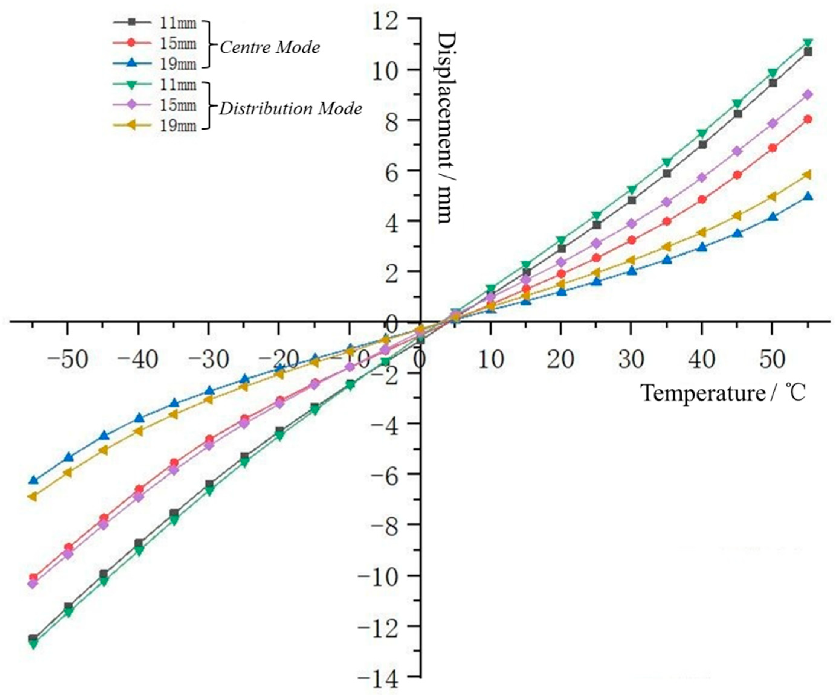
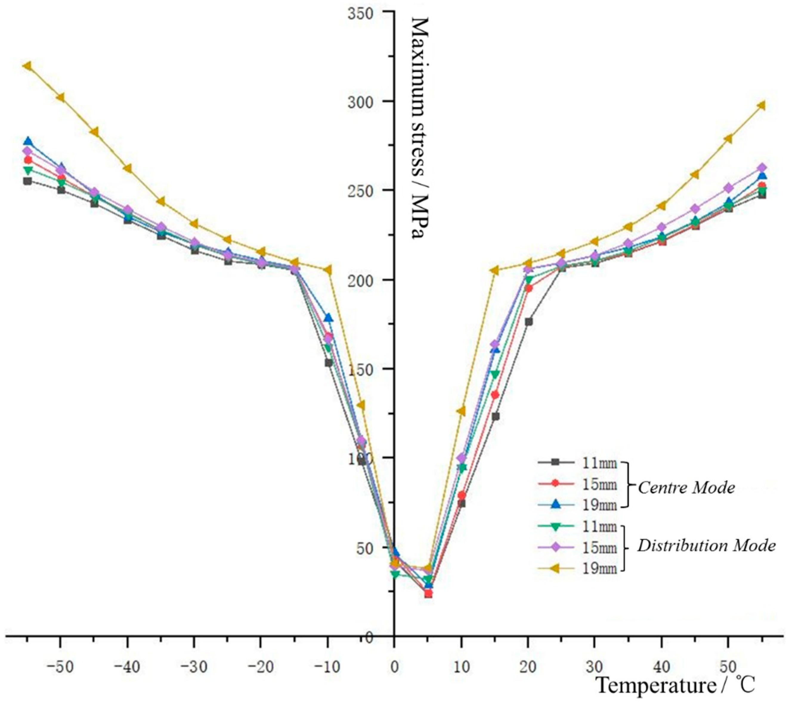
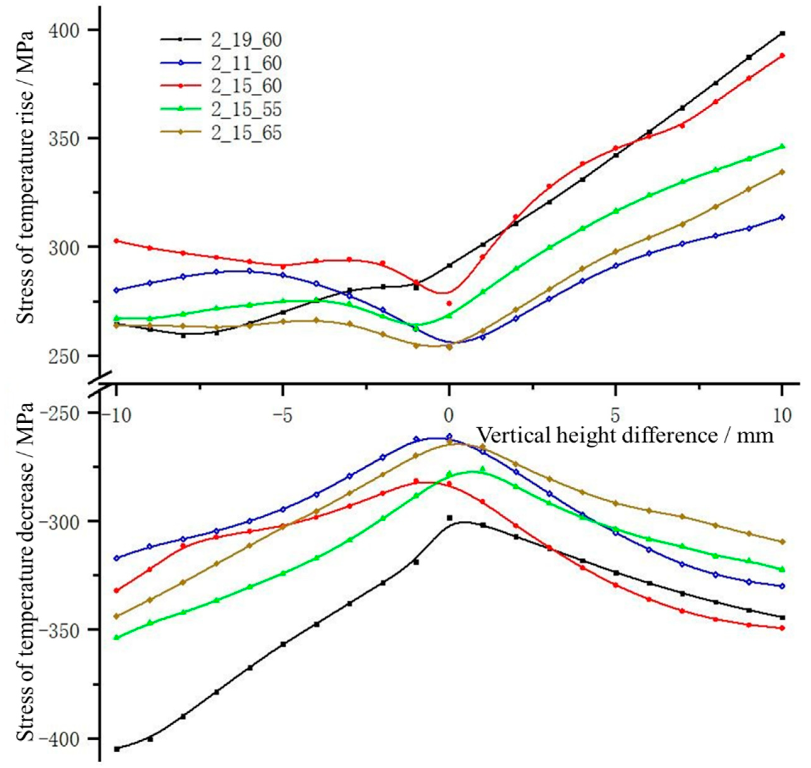
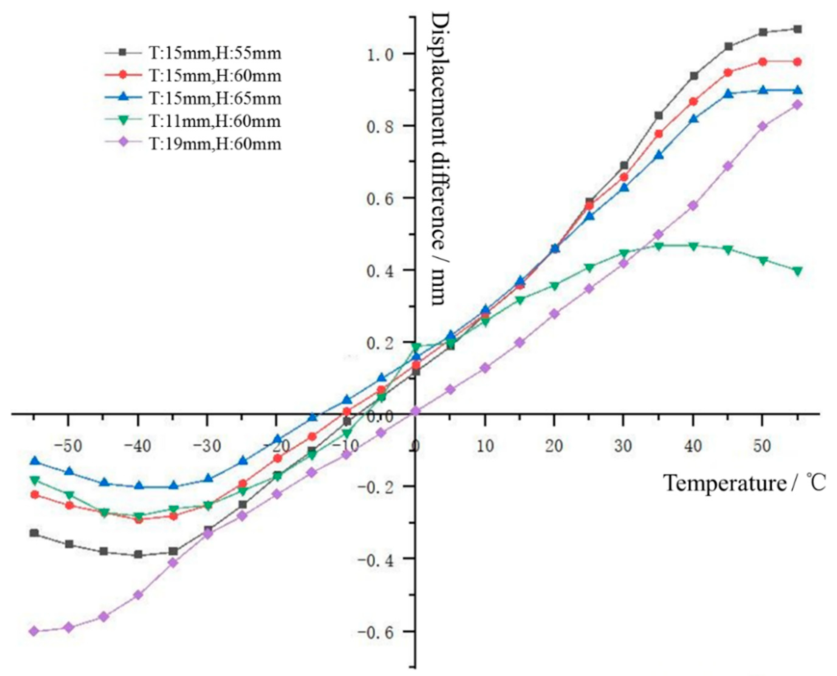
4.1. Simulation Results of Structural Dimensions of Shell Bellows

Section 2 explained that the end of the bellows close to the support leg of the GIS equipment is more constrained in the process of compression and tension than the end further from the support leg, and the corresponding deformation is more obvious, which means that the yield limit can be reached faster in the compensation process. Therefore, the simulation results of the bellows close to the support leg were extracted for discussion and analysis in this paper.
(a)
Wall thickness of bellows
When investigating the influence of the wall thickness of the bellows on the compensation capacity, taking the temperature change as the abscissa and the compression (elongation) amount and maximum stress value of the bellows as the ordinate, the compression (elongation) amount–temperature change curve and the maximum stress value–temperature change curve of the bellows were drawn according to the simulation results. When the longitudinal axis represents the compression (elongation) amount of the bellows, a value greater than zero indicates that the bellows are in a compressed state, whereas a value less than zero indicates that the bellows are in a tensile state. Figure 6 shows the compression (elongation) amount–temperature change curve of bellows with different wall thicknesses, and Figure 7 shows the maximum stress value–temperature change curve of bellows with different wall thicknesses.
According to the curve data of 1_11_60, 1_15_60 and 1_19_60, and 2_11_60, 2_15_60 and 2_19_60 group models in Figure 6, it can be calculated that when the temperature rises by 55 °C, the compression amount of the three bellows with a centralized arrangement is reduced by 2.67 and 3.05 mm for every 4 mm increase in wall thickness, which is reduced to 75.09% and 62.11% of the original compression amount, respectively. By comparison, the compression amount of the bellows with a distributed arrangement is reduced by 2.09 and 2.17 mm with the increase in wall thickness, which is reduced to 81.21% and 64.89% of the original compression amount, respectively. When the temperature decreases by 55 °C, the elongation of the three bellows with a centralized arrangement is reduced by 2.42 and 3.83 mm for every 4 mm increase in wall thickness, which is reduced to 80.67% and 62.08% of the original elongation respectively; by comparison, the elongation of the bellows with distributed arrangement is reduced by 2.38 and 3.45 mm, which is reduced to 18.74% and 33.43% of the original compensation, respectively. It can be found that, for bellows with the same layout, the compensation amount of temperature variation displacement of the GIS equipment is negatively correlated with the wall thickness; that is, the thinner the wall, the greater the compensation amount of the bellows.
Comparing the curve data of the same two groups of models in Figure 7, it can be calculated that, when the temperature rises by 55 °C, the maximum stress value of the three corrugated pipes with a centralized arrangement increases by 5.05 and 5.31 MPa for every 4 mm increase in wall thickness, i.e., about 2.04% and 2.11% compared to before the change, whereas the maximum stress value of the corrugated pipes with a distributed arrangement increases by 12.64 and 34.82 MPa with the increase in wall thickness, i.e., about 5.04% and 13.23% compared to before the change. When the temperature drops by 55 °C, the maximum stress value of the three bellows with a centralized arrangement increases by 11.77 and 9.75 MPa for every 4 mm increase in wall thickness, i.e., about 4.6% and 3.64% compared to before the change, whereas the maximum stress value of the three bellows with a distributed arrangement increases by 10.17 and 47.64 MPa, i.e., about 3.88% and 17.49% compared to before the change.
Secondly, it can be seen from Figure 7 that the maximum stress–temperature curve of bellows with different wall thicknesses has an obvious turning phenomenon near 205 MPa, which just reflects two different working stages of the bellows, namely elastic deformation and plastic deformation. However, regardless of whether the bellows are in the stage of elastic deformation or plastic deformation, the maximum stress value of the bellows under the same arrangement is positively correlated with the wall thickness; that is, under the same temperature change, the thicker the wall, the greater the maximum stress value generated by the bellows in the process of deformation.
In summary, when the wall thickness of the bellows in the control group was reduced from 15 to 11 mm, its compensation ability for the temperature change displacement of the GIS equipment increased by about 26% and the maximum stress value decreased by about 4%. When the wall thickness of the bellows was thickened from 15 mm, by 4 mm, its compensation ability for the temperature change displacement of the GIS equipment decreased by about 36% and the maximum stress value increased by about 9%. Therefore, in practical applications, the compensation capacity of the bellows can be improved and the stress level of the bellows can be reduced by configuring bellows that meet the design standards but have relatively thin walls.
(b)
Wave height of bellows
When investigating the influence of the change in the wave height of the bellows on the compensation capacity, the compression (elongation)–temperature change curve and the maximum stress value–temperature change curve of the bellows with different wave heights were drawn, according to the same rules as those of Figure 6 and Figure 7, as shown in Figure 8 and Figure 9. According to the curve data of 1_15_55, 1_15_60 and 1_15_65 models, and 2_15_55, 2_15_60 and 2_15_65 models in Figure 8, it can be calculated that when the temperature increases by 55 °C, the compression of the three bellows with a centralized arrangement increases by 0.53 and 0.43 mm for every 5 mm increase in wave height, which is 7.5% and 5.34% higher than the original compression, whereas the compression of the bellows with a distributed arrangement increases by 0.44 and 0.35 mm, which is 5.12% and 3.88% higher than the original compression. When the temperature decreases by 55 °C, the elongation of the three bellows with a centralized arrangement increases by 0.6 and 0.5 mm for every 5 mm increase in wave height, which is about 6.32% and 4.95% of the elongation before the change, whereas the elongation of the bellows with a distributed arrangement increases by 0.49 and 0.41 mm with the increase in wave height, which is about 4.98% and 3.97% of the elongation before the change. It can be found that when the temperature of the bellows with the same arrangement changes, the compensation amount of the bellows is positively correlated with the wave height; that is, the greater the wave height, the greater the compensation amount of the bellows.
By comparing the curve data of the same two groups of models in Figure 9, it can be calculated that, when the temperature rises by 55 °C, the maximum stress value of the three bellows with a centralized arrangement decreases by 3.7 and 7.8 MPa for every 5 mm increase in wave height, down to 98.56% and 96.92% of the original maximum stress value, whereas the maximum stress value of the bellows with a distributed arrangement decreases by 3.3 and 9.39 MPa with the increase in the wave height, i.e., a reduction to 98.76% and 96.43% of the original maximum stress value, respectively. When the temperature decreases by 55 °C, the maximum stress value of the three bellows with a centralized arrangement decrease by 6.5 and 8.1 MPa for every 5 mm increase in wave height, respectively, to 97.63% and 96.97% of the original maximum stress value, whereas the maximum stress value of the three bellows with a distributed arrangement decreases by 3.43 and 7.81 MPa with the increase in wave height, respectively, to 98.76% and 97.13% of the original maximum stress value.
The maximum stress–temperature curve of the bellows with different wave heights in Figure 9 also has an obvious turning point near 205 MPa due to the material properties of the bellows, which is related to the dividing point of the elastic deformation and plastic deformation of the bellows. However, regardless of whether the bellows are in the elastic deformation stage or the plastic deformation stage, the maximum stress value of the bellows under the same arrangement is negatively correlated with the wave height; that is, under the same temperature change, the higher the wave, the smaller the maximum stress value generated by the bellows in the deformation process.
In summary, after reducing the wave height of the bellows in the control group from 60 to 55 mm, their compensation ability for the temperature change displacement of the GIS equipment decreased by about 6%, and the maximum stress value increased by about 2%. After increasing the wave height from 60 to 65 mm, the bellows’ compensation ability for the temperature change displacement of the GIS equipment increased by about 5% and the maximum stress value decreased by about 3%. In practical applications, the compensation capacity of the bellows can be improved and the stress level of the bellows can be reduced by configuring bellows that meet the design standards but have a relatively high wave.
It should be pointed out that, due to gravity and the SF6 gas pressure in GIS equipment, even if the temperature does not change, the bellows will deform to a certain extent, and the deformation direction is opposite to that of the bellows during an increase in temperature and the same as that of the bellows during a decrease in temperature. Therefore, the maximum stress value–temperature change curve under a heating condition shows a decrease or no obvious change when the temperature begins to change, and the initial value of the ordinate of the compression (elongation) amount–temperature change curve is not zero.

4.2. Simulation Results of Coaxiality of Shells on Both Sides of Bellows

According to the simulation results, the height difference of the shell on both sides of the bellows is taken as the abscissa; that is, the displacement difference between the fixed support leg base and the sliding support leg base along the positive direction of the z-axis. When the fixed support leg base is lower than the sliding support leg base, a negative value is taken, otherwise a positive value is taken. The compression (elongation) and maximum stress value of the corrugated pipe are taken as the ordinate, respectively, to draw the heating condition curve and cooling condition curve, as shown in Figure 10 and Figure 11. However, the positive and negative values of the ordinate here only represent the heating and cooling conditions, rather than directionality.
It can be seen from the compression (elongation) curve of the bellows that the influence of the cylinder shape on the ability of the bellows to compensate for the temperature-dependent displacement is monotonous; that is, the compensation amount of the bellows for the temperature-dependent displacement gradually increases with the lifting of the base of the fixed support leg. The reason for this is that the lifting of the base causes the fixed support leg to share more weight of the GIS shell and reduces the pressure between the lower surface of the sliding support leg and the base. Furthermore, the friction between the two is reduced, which is more conducive to the sliding support leg cooperating with the bellows to compensate for the temperature change displacement. When the height difference on both sides of the bellows reaches 10 mm, the compression of bellows of different sizes increases by a maximum of 29.9% when heating and the elongation increases by 20.4% when cooling. Conversely, the compression (elongation) of the bellows decreases as the fixed support leg drops and the sliding support leg shares more of the GIS weight. When the height difference between the two sides of bellows reaches −10 mm, the compression of the bellows of different sizes decreases by a maximum of 46.5% and the elongation decreases by a maximum of 20.4% during cooling. The stress value of the bellows is generally reduced to the minimum when the axis of the shell body remains horizontal. When the height difference of the shell body on both sides of the bellows occurs, regardless of the increase or decrease in the compression (elongation), the stress value increases, especially when the fixed support leg base is higher than the sliding support leg base. Among the five sizes of bellows, the maximum stress is increased by 1.42 times compared with the stress value of the axis of the shell is horizontal.
It is worth noting that the influence of cylinder geometry on the temperature compensation ability of the bellows does not show symmetry related to the temperature change. Comparing the temperature rise curve and temperature drop curve, it can be found that when the GIS shell temperature decreases, the fluctuation range of the stress and strain of bellows is relatively narrow compared with the temperature rise curve, because the compensation of the height difference on both sides of bellows is related to the axial size. When cooling, the bellows are stretched, which improves their compensation ability for the height difference on both sides to a certain extent, and reduces the impact of the lifting or settlement of the base of the fixed support leg.
To summarize, when the base of the sliding support leg is higher than the base of the fixed support leg, the lower surface of the sliding support leg is subjected to greater friction. This is equivalent to a partial failure of the sliding support leg, which is not conducive to the temperature change displacement compensation of the bellows. When the base of the sliding support leg is lower than the base of the fixed support leg, the friction between the sliding support leg and the base is reduced; this is conducive to the sliding support leg cooperating more smoothly with the bellows to achieve the temperature change displacement compensation. Nonetheless, it increases the stress value of the bellows and threatens the safe and stable operation of GIS equipment.

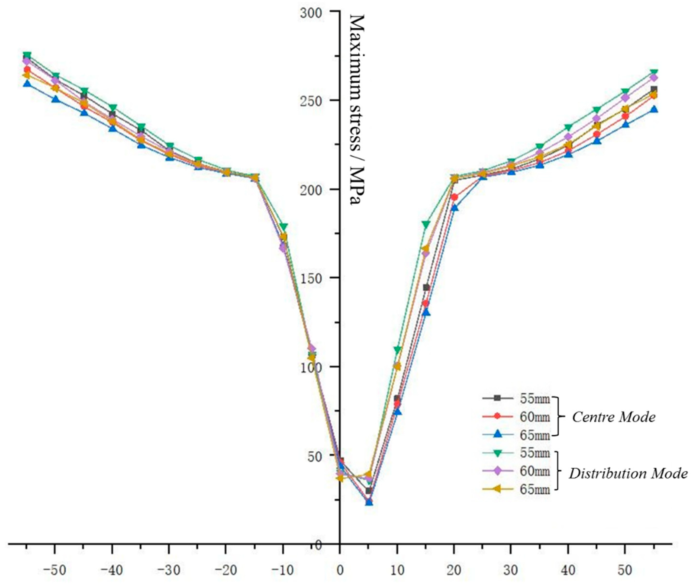
4.3. Arrangement of Shell Bellows

According to the simulation results, the difference between the compression (elongation) of distributed bellows having the same structural size and the compression (elongation) of centralized bellows was calculated, and the value was taken as the ordinate and the temperature change as the abscissa to draw the difference in the temperature change curves of compression (elongation) of different layout modes, as shown in Figure 12.
It can be seen from the curves that the difference between distributed and centralized compression (elongation) is greater than zero in the heating condition, which shows that, in the heating condition, the bellows having a distributed arrangement are better than the bellows having a centralized arrangement at absorbing the expansion of the GIS equipment shell. In the part of the curve under the cooling condition, when the cooling range exceeds 15 °C, the difference between distributed and centralized compression (elongation) is less than zero; that is, when the cooling range exceeds 15 °C, the distributed bellows can compensate for greater shrinkage of the GIS equipment shell due to cooling. At the same time, the difference between the distributed and centralized compression (elongation) and the temperature change satisfies the quadratic function under both heating and cooling conditions. After fitting the data, the statistical correlation coefficient and the sum of squares of residuals are listed in Table 3, which further show that there is a strong correlation between the difference between the distributed and centralized displacement and the temperature change. In addition, because each curve presents the form of a quadratic function in the heating and cooling sections, in addition to the intersection with the abscissa shown in Figure 10, there must be an intersection greater than zero and an intersection less than zero, which are recorded as tup and tdown respectively; that is, when the heating range is greater than tup or the cooling range is less than tdown, the bellows compensation amount with a distributed arrangement will be less than that with a centralized arrangement. The tup and tdown of each curve were accurately calculated and rounded by the fitted function equation, and are listed in Table 3. It can be found that the temperature change in the daily working environment rarely reaches the values of tup and tdown. In conclusion, the distributed arrangement of the bellows is more conducive to improving the compensation capacity of the bellows.
Moreover, based on the above analysis, regardless of the distribution mode adopted, when the temperature does not change, the compression (elongation) of the bellows is negative; that is, in the tensile state, the difference between the compression (elongation) of the distributed and centralized bellows with five different structural sizes in Figure 10 is positive when the temperature remains unchanged. This shows that the elongation of the distributed bellows is less than that of the centralized bellows without a temperature change. On average, the initial shape variable of the distributed bellows is only 80% of that of the centralized bellows; that is, the separate arrangement of the bellows is conducive to resisting the initial deformation caused by the gravity of the structure and the internal air pressure of the GIS equipment, and improving the ability to compensate for temperature changes.

4.4. Discussion

According to the simulation data of the above scenario, the temperature variation displacement compensation behavior of the bellows of GIS equipment is not only affected by their own structural size, but is also related to the shape and layout of the GIS shell. Among these factors, the influence of the bellows’ structural size is the most significant, followed by the shape of GIS shell, and the layout has the least influence. The amount of compensation of the bellows is positively correlated with the wave height. The higher the wave, the greater the compensation amount of the bellows, which is negatively correlated with the wall thickness. The thinner the wall, the greater the compensation amount of the bellows, and the influence of the wall thickness is more significant than that of the wave height. Bellows with thin walls and high waves can not only effectively improve the temperature variation displacement compensation capacity of the bellows, but also alleviate the stress concentration phenomenon in the compensation process. On the premise of meeting the strength requirements, bellows with thin walls and high waves should be preferred for GIS shell bellows. The distributed layout is beneficial to resisting the initial deformation caused by the gravity of the structure and the internal air pressure of the GIS equipment, and improving the compensation ability for temperature changes. The bellows has the best performance in terms of compensating for temperature variation displacement when the axis of the external shell is horizontal. Unequal heights of the sliding pin of the shell and the fixed pin are not conducive to alleviating the phenomenon of stress concentration. In particular, when the base of the cylinder on the side of the sliding support leg is higher than the cylinder on the side of the fixed support leg, the bellows needs to overcome greater friction during extension and contraction. As the main body of the GIS equipment, having a large span, the bellows’ geometry has an impact not only on the temperature variation displacement compensation ability of the bellows, but also on their own temperature variation behavior. In the evaluation of the temperature-dependent displacement behavior of GIS equipment in the project, we should not only pay attention to the selection and design of bellows to ensure the installation quality of the project, but also the changes in the shell geometry caused by foundation settlement and gravity in the later operation and maintenance. In addition, the shell shape, temperature change range, sliding support pin constraints, and other factors should also be comprehensively considered.

5. Conclusions

By constructing a geometric simulation model of the coupling of the GIS shell pin bellows, this study simulated and examined the coupling relationship and law between the temperature displacement compensation performance of the bellows and their geometric structure, size, and layout, and the coaxiality of the shells on both sides. The research results can provide a reference for the engineering selection, installation, operation, and maintenance of GIS shell bellows. The main conclusions of the research work are as follows:
  • The temperature-dependent displacement compensation behavior of the GIS shell bellows is related to their own structural size, GIS shell shape, and layout. The influence of the bellows’ structural size is the most significant, the influence of GIS shell shape is ranked second, and the influence of layout is the least significant.
  • Within the scope allowed by the design standard, bellows with thin walls and large wave height should be selected. This can effectively improve the temperature variation displacement compensation ability of the bellows and reduce the stress concentration in the compensation process. When the wave height of the bellows is increased, their compensation capacity increases by about 5% and the maximum stress value decreases by about 3%. When the wall thickness of the bellows is reduced, their compensation capacity increases by about 26% and the maximum stress value decreases by about 4%. The influence of the wall thickness is more significant than that of the wave height.
  • Within the temperature variation range of daily work, the compensation capacity of distributed bellows is better than that of centralized bellows, and can alleviate the initial deformation caused by gravity and gas pressure in GIS equipment. In this case, the initial shape variable of distributed bellows is only 80% of that of centralized bellows.
  • The influence of the shell shape on the temperature variation displacement compensation ability of the bellows mainly relates to changing the friction between the sliding support leg and the base. When the base of the sliding support leg is lower than the base of the fixed support leg, the temperature variation displacement compensation of the bellows increases, whereas the temperature compensation ability of the bellows increases. However, both cases are not conducive to alleviating the phenomenon of stress concentration. In the case study, the maximum stress is increased by 1.42 times compared with the stress value of the axis of the shell is horizontal.
  • The geometry of the GIS equipment shell has an impact not only on the temperature change displacement compensation ability of the bellows, but also on their own temperature change behavior. The next work will focus on the temperature change behavior of GIS equipment under the coupling of the geometry of the bellows and the shell.

Author Contributions

Put forward demand and investigation, X.L. and T.B.; Lead the research scheme and supervision, X.S.; Simulation and writing original draft, H.X. All authors have read and agreed to the published version of the manuscript.

Funding

Appreciated for the support of China Southern Power Grid science and technology project 080042KK52190006 (GZHKJXM20190039) for this work.

Institutional Review Board Statement

Not applicable.

Informed Consent Statement

Not applicable.

Data Availability Statement

Not applicable.

Conflicts of Interest

The authors declare no conflict of interest.

References

  1. Liu, Z.; Wang, C.; Lu, S.; Sun, G.; Wang, N.; Li, P.; Yu, Z.; Zhang, P. Key technical requirements of UHV Gil for Sutong utility tunnel project. Power Grid Technol. 2020, 44, 2377–2385. [Google Scholar]
  2. Wang, Z.; Gao, J.; Wang, R.; Chen, K.; Gao, Z.; Jiang, Y. Failure mode and effects analysis using Dempster-Shafer theory and TOPSIS method: Application to the gas insulated metal enclosed transmission line (GIL). Appl. Soft Comput. 2018, 70, 633–647. [Google Scholar] [CrossRef]
  3. Cong, H.; Jin, H. Research on Undetected Overheat Fault of the GIS Bus Bar Contacts Based on Infrared Thermal Imaging. J. Electr. Eng. Technol. 2019, 14, 839–848. [Google Scholar] [CrossRef]
  4. General Office of State Grid Corporation of China. Anti Accident Measures and Fault Analysis Report on Expansion Joint of Outdoor GIS Equipment; General Office of State Grid Corporation of China: Beijing, China, 2015. [Google Scholar]
  5. Fang, H.; Tan, P.; Du, X.; Li, B.; Yang, K.; Zhang, Y. Numerical and Experimental Investigation of the Effect of Traffic Load on the Mechanical Characteristics of HDPE Double-Wall Corrugated Pipe. Appl. Sci. 2020, 10, 627. [Google Scholar] [CrossRef] [Green Version]
  6. You, Q.; Miao, L.; Dong, D. Analysis of mechanical properties of steel bellows. J. Southeast Univ. (Nat. Sci. Ed.) 2017, 47, 1187–1194. [Google Scholar]
  7. Kunpeng, W.E.I.; Xingjian, D.A.I.; Zongyi, S.H.A.O. Measurement and finite element analysis of bending stiffness of carbon fiber bellows. J. Tsinghua Univ. (Nat. Sci. Ed.) 2019, 59, 587–592. [Google Scholar]
  8. Fang, H.; Tan, P.; Du, X.; Li, B.; Yang, K.; Zhang, Y. Mechanical response of buried HDPE double-wall corrugated pipe under traffic-sewage coupling load. Tunn. Undergr. Space Technol. 2021, 108, 103664. [Google Scholar] [CrossRef]
  9. Sellappan, A.; Chandrasekharan, M.; More, S.; Kamble, D.; Janghel, D. Reliable design of bellows and end components for vacuum interrupters having longer stroke length. In Proceedings of the 2014 International Symposium on Discharges and Electrical Insulation in Vacuum, Mumbai, India, 28 September–3 October 2014; pp. 477–480. [Google Scholar]
  10. Hong, L.; Ai, S.; Xie, H.; Du, W.; Yao, X.; Zhang, B.; Liu, P.; Liu, Z.; Wang, J.; Geng, Y.; et al. Fatigue life simulation of vacuum interrupter bellows subjected to high gas pressure and high operating velocity. In Proceedings of the 2017 4th International Conference on Electric Power Equipment—Switching Technology, Xi’an, China, 22–25 October 2017; pp. 633–636. [Google Scholar]
  11. Chen, T.; Su, M.; Pan, C.; Zhang, L.; Wang, H. Local buckling of corrugated steel plates in buried structures. Thin-Walled Struct. 2019, 144, 106348. [Google Scholar] [CrossRef]
  12. Zinovieva, T.V.; Smirnov, K.K.; Belyaev, A.K. Stability of corrugated expansion bellows: Shell and rod models. Acta Mech. 2019, 230, 4125–4135. [Google Scholar] [CrossRef]
  13. Yuan, Z.; Huo, S.; Ren, J. Mathematical description and mechanical characteristics of reinforced S-shaped bellows. Int. J. Press. Vessel. Pip. 2019, 175, 103931. [Google Scholar] [CrossRef]
  14. Tomarov, G.V.; Shipkov, A.A. Bellows Expansion Joints of the Main Heating Network Pipelines: Problems and Damage Prevention. Therm. Eng. 2019, 66, 367–371. [Google Scholar] [CrossRef]
  15. GB/T-16749-2018; Pressure Vessel Wavy Expansion Joint. National Standardization Administration of China: Beijing, China, 2018.
  16. State Grid Corporation of China. Technical Standard for Gas Insulated Metal Enclosed Switchgear; China Electric Power Press: Beijing, China, 2012. [Google Scholar]
  17. GB/T 30092-2013; Metal Bellows Compensator for High Voltage Switchgear. National Standardization Administration of China: Beijing, China, 2013.
  18. Zhang, D.W.; Shi, T.L.; Zhao, S.D. Through-Process Finite Element Modeling for Warm Flanging Process of Large-Diameter Aluminum Alloy Shell of Gas Insulated (Metal-Enclosed) Switchgear. Materials 2019, 12, 1784. [Google Scholar] [CrossRef] [PubMed] [Green Version]
  19. Zebouchi, N.; Haddad, M.A. A Review on Real-Size Epoxy Cast Resin Insulators for Compact High Voltage Direct Current Gas Insulated Switchgears and Gas Insulated Transmission Lines—Current Achievements and Envisaged Research and Development. Energies 2020, 13, 6414. [Google Scholar] [CrossRef]
  20. Kim, J.K.; Hahn, S.C.; Park, K.Y.; Kim, H.K.; Oh, Y.H. Temperature rise prediction of EHV GIS bus bar by coupled magnetothermal finite element method. IEEE Trans. Magn. 2005, 41, 1636–1639. [Google Scholar]
  21. State Grid Corporation of China. Process Standard Library of Power Transmission and Transformation Engineering of State Grid Corporation of China; Electric Power Press: Beijing, China, 2012. [Google Scholar]
Figure 1. Structural diagram of U-shaped bellows. D—the inner diameter of the straight side section of the bellows; h—the wave height; ric—the curvature radius of the outer wall of the wave crest; rir—the curvature radius of the outer wall of the wave trough; t—the wall thickness; q—the wave distance.
Energies 15 03954 g001
Figure 2. Geometry of GIS shell.
Energies 15 03954 g002
Figure 3. Arrangement of bellows in GIS: (a) distributed layout; (b) centralized layout.
Energies 15 03954 g003
Figure 4. Schematic diagram of the site layout scheme of the case analysis object: (a) distributed layout; (b) centralized layout.
Energies 15 03954 g004aEnergies 15 03954 g004b
Figure 5. Stress–strain curve of 06cr19ni10 material.
Energies 15 03954 g005
Figure 6. Displacement–temperature curve of bellows with different wall thicknesses.
Energies 15 03954 g006
Figure 7. Temperature–stress curve of corrugated pipe with different wall thicknesses.
Energies 15 03954 g007
Figure 8. Displacement–temperature curve of bellows with different wave heights.
Energies 15 03954 g008
Figure 9. Maximum stress–temperature curve of bellows with different wave heights.
Energies 15 03954 g009
Figure 10. Temperature variation displacement curve.
Energies 15 03954 g010
Figure 11. Bellows stress curve.
Energies 15 03954 g011
Figure 12. Difference between displacement and temperature curves of different arrangements.
Energies 15 03954 g012
Table 1. Axial length of case object structure.
Part NumberShell
A
Below AShell
B
Shell
C
Shell
D
InsulatorShell
E
Shell
F
Shell
B
Shell
G
Axial length (m) of distributed layout2.8350.4162.6011.3992.6050.1420.2682.5680.4162.649
Axial length (m) of centralized layout2.8350.8322.6011.3992.6050.1420.2682.568-2.649
Table 2. Structural materials and properties of GIS equipment components.
PositionMaterialModulus
of Elasticity
N/m2
Poisson’s RatioDensity
kg/m3
Coefficient
of Thermal Expansion
m/°C
Support legQ2352.1 × 10110.27478301.2 × 10−5
BaseQ2352.1 × 10110.27478301.2 × 10−5
Shell bodyZL114A7.0 × 10100.33027002.3 × 10−5
InsulatorEpoxy resin8.5 × 1090.3309805.9 × 10−5
Table 3. Statistics of the fitting equation of the compensation difference of bellows of different sizes in different layouts.
No.Bellows SizeR SquareSum of Squares of ResidualsTupTdown
1Wall thickness: 11 mm
Wave height: 60 mm
0.976880.0028788−68
0.99410.00136
2Wall thickness: 15 mm
Wave height: 55 mm
0.986780.01783360−85
0.97990.00731
3Wall thickness: 15 mm
Wave height: 60 mm
0.987330.01357300−76
0.98210.00435
4Wall thickness: 15 mm
Wave height: 65 mm
0.987960.01007240−70
0.97810.00378
5Wall thickness: 19 mm
Wave height: 60 mm
0.998720.00114374−151
0.991030.0046
Publisher’s Note: MDPI stays neutral with regard to jurisdictional claims in published maps and institutional affiliations.

