Article

Preparation of a Honeycomb-like FeNi(OH/P) Nanosheet Array as a High-Performance Cathode for Hybrid Supercapacitors

The State Key Laboratory of Refractories and Metallurgy, Institute of Advanced Materials and Nanotechnology, College of Materials and Metallurgy, Wuhan University of Science and Technology, Wuhan 430081, China
*
Authors to whom correspondence should be addressed.
Energies 2022, 15(11), 3877; https://doi.org/10.3390/en15113877
Submission received: 29 April 2022 / Revised: 22 May 2022 / Accepted: 22 May 2022 / Published: 24 May 2022
(This article belongs to the Topic Energy Storage and Conversion Systems)

Abstract

:
Polymetallic transition metal phosphides (TMPs) exhibit quasi-metallic properties and a high electrical conductivity, making them attractive for high-performance hybrid supercapacitors (HSCs). Herein, a nanohoneycomb (NHC)-like FeNi layered double hydroxide (LDH) array was grown in situ on 3D current collector nickel foam (NF), which is also the nickel source during the hydrothermal process. By adjusting the amount of NaH2PO2, an incomplete phosphated FeNi(OH/P) nanosheet array was obtained. The optimized FeNi(OH/P) nanosheet array exhibited a high capacity up to 3.6 C cm−2 (408.3 mAh g−1) and an excellent long-term cycle performance (72.0% after 10,000 cycles), which was much better than FeNi LDH’s precursor. In addition, the hybrid supercapacitor (HSC) assembled with FeNi(OH/P) (cathode) and polypyrrole (PPy/C, anode) achieved an ultra-high energy density of 45 W h kg−1 at a power density of 581 W kg−1 and an excellent cycle stability (118.5%, 2000 cycles), indicating its great potential as an HSC with a high electrochemical performance.

1. Introduction

The energy crisis and global climate change have stimulated the search for sustainable energy. Numerous efforts have been made to develop energy storage devices that are efficient, economical, safe, and environmentally friendly in order to meet the future development of a low-carbon, sustainable economy. Batteries have a high energy density, but a low power density and poor cycling stability. Supercapacitors have a higher power density, faster charging time, and better long-term stability than batteries. However, supercapacitors have limited industrial applications because of their low energy density. By combining the advantages of batteries and supercapacitors, researchers proposed a hybrid supercapacitor (HSC) with a battery-type electrode and a capacitive electrode. Compared with carbon-based materials storing energy via a double electric layer, battery-type electrode materials can generate extreme energy density based on an active redox reaction [1,2]. Therefore, the performance of HSC is highly dependent on the efficiency and stability of the battery-type electrodes.
Recently, it has been demonstrated that transition-metal phosphides (TMPs) have garnered significantly more research because of their higher conductivity, electrochemical activity, and structural stability [3,4], all of which make them potentially useful in energy storage devices. TMP is a triangular prism made of metal bonds or covalent chemical bonds [5]. By increasing the number of metal atoms situated in the center of the prism’s vertical plane, a nine-fold tetrakaidecahedron structure centered on phosphorus atoms is formed. The large channels and open framework of TMPs provide effective electron/ion transport. Because of the rapid reduction in ionic properties and the “P” dragging electron density in the sublattice presence of delocalization, TMPs have more free electrons, which is the fundamental reason for their higher conductivity. After the introduction of metals into the monometallic phosphide, the resulting polymetallic (or metal-rich) transition metal phosphide (e.g., MP or M2P, where M is the transition metal) exhibits metallic properties (chemical stability), multiple redox centers, and the ability to carry more free electrons, resulting in a significantly increased electrical conductivity (compared with phosphorus-rich or monometallic phosphides) [6]. However, phosphorus-rich TMPs with abundant P−P bonds are unsuitable as energy storage materials because of the electron accumulation around the P atoms and decreased electrochemical performance [7]. Thus, understanding how to select appropriate metals and combine them to form multi-component metal phosphides with synergistic effects is critical for optimizing the electrochemical performance of electrochemical energy storage devices using TMPs as electrodes.
Recently, it was discovered that one of most effective tactics to improve the electrochemical performance is to combine Ni and Fe to form bimetallic phosphide, which improves the conductivity of Fe/Ni-based compounds [8,9]. The electrochemical properties of Ni and Fe are quite similar; the ionic radius of Fe3+(0.65 Å) is close to that of Ni2+(0.69 Å) [10,11]. As a result of the formation of hydroxyl oxides during charge storage, Ni and its compounds in various morphologies (e.g., nanoparticles, nanowires, and thin films) are typical supercapacitor electrode materials with an excellent redox behavior. Because of its high theoretical capacity (1951.2 C g−1) and good electronic conductivity (1.2 × 10⁻³ S cm−1) [12], Ni2P is considered as a promising material for energy storage. However, because of structural degradation, the stability of FeNi-based materials is still unsatisfactory [9]. In recent years, many binder-free nanoarray electrodes with self-contained nano-units and porous structures have been investigated to minimize the volume expansion and improve the electrochemical performance. As a result of phosphorus’s lower electronegativity and reduced bond ionicity, Fe/Ni bimetal phosphides give a series of various redox couples (Fe0/Fe2+/Fe3+, Ni0/Ni1+/Ni2+) with better metalloid properties [13]. Although there have been many reports about Ni/Fe bimetal phosphides as high-performance electrocatalysts for water splitting [14,15,16], their use as electrodes in SCs is unclear [17].
In this study, we designed, synthesized, and developed self-supported nanohoneycomb (NHC)-like FeNi(OH/P) electrodes using a simple two-step procedure, in which incomplete phosphated FeNi(OH/P) nanosheet arrays were oriented and anchored on 3D nickel foam without any bridging agent. The large contact areas and electron pathways of the unique interconnected NHC-like FeNi(OH/P) nanosheet array could provide high-efficiency electronic transmission for the charge storage. Furthermore, Ni/Fe bimetal phosphides have high density redox centers and a high conductivity. This study also describes a hybrid supercapacitor (HSC) with a cathode electrode made of bimetallic transition phosphides and an anode electrode made of polypyrrole/C (PPy/C). By optimizing gel electrolytes, the HSC exhibited excellent capacity retention. This work provides a new strategy for designing a cost-effective, reliable, and high-performance asymmetric supercapacitor for energy storage applications.

2. Materials and Methods

2.1. Materials

Nickel chloride hexahydrate (NiCl2·6H2O), ferric chloride hexahydrate (FeCl3·6H2O), sodium chloride (NaCl), and sodium hypophosphite (NaH2PO2·H2O) were purchased from Sinopharm Chemical Reagents Co., Ltd. All of the reagents were of analytical grade and were used without further purification.

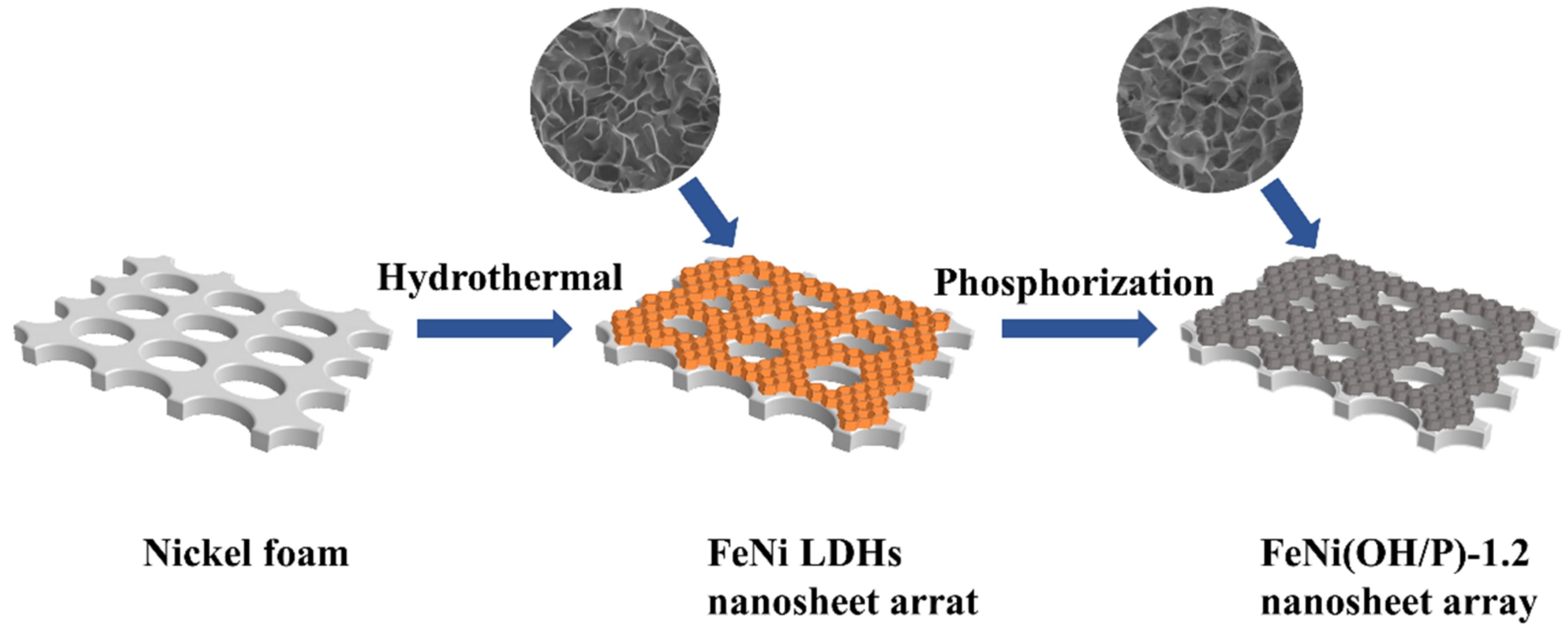
2.2. Synthesis of Materials

2.2.1. Synthesis of FeNi LDH’s Precursor

First, the nickel foam (NF, 5.2 × 3.7 cm2) was cleaned with 2 M HCl, absolute ethanol, and deionized water by sonication for 15 min in sequence to remove the oxide layer on the surface. Then, 0.27 g FeCl3·6H2O [18,19] and 0.097 g NaCl were dissolved in 70 mL of deionized water by magnetic stirring for 30 min. The mixed solution and a piece of the pretreated NF were transferred to a 100 mL Teflon-lined stainless autoclave and kept at 120 °C for 10 h. The Ni foam coated with the FeNi LDH sample was washed alternately with ethanol and deionized water several times, and dried for 5 h at 60 °C. The mass density of the FeNi LDH nanosheet array (0.57 mg cm−2) on the NF was determined by subtracting the weight of the NF (after acid etching) from the weight of the FeNi LDHs with the NF.

2.2.2. Synthesis of the FeNi(OH/P) Sheet Array Electrode

The NaH2PO2 and Ni foam-supported FeNi LDH were placed upstream and downstream of the tube furnace, respectively. The samples were heated to 300 °C at a heating rate of 2 °C min−1 for 2 h under an Ar flow. The FeNi(OH/P) was collected after the furnace was cooled to an ambient temperature. To explore the effect of the phosphorization degree, we considered NiFe(OH/P) with different amounts of NaH2PO2 (0 g, 0.6 g, 1.2 g, and 1.8 g, defined as FeNi(OH/P)-0, FeNi(OH/P)-0.6, FeNi(OH/P)-1.2, and FeNi(OH/P)-1.8, respectively). After phosphating, the mass increased by 1.87 mg cm−2 on average. The mass density of the FeNi(OH/P)-1.2 nanosheet array on the NF was 2.44 mg cm−2.

2.2.3. Assembly of Hybrid Supercapacitor Device

All-solid-state hybrid supercapacitors (HSCs) were assembled by employing the as-fabricated FeNi(OH/P)-1.2 and PPy/C as the cathode and anode electrode, respectively, and PVA/KOH/PAAS as the electrolyte.
For the preparation of PPy/C, PPy aerogel was heated to 500 ℃ at a rate of 5 ℃ min−1 under an argon atmosphere. The preparation of PPy aerogel was mentioned in previous articles from our group [20]. PPy aerogel was synthesized through PPy hydrogels, which were obtained by oxidizing the pyrrole monomer with ammonium peroxysulfate (APS) in a Methyl orange (MO) solution. The mixture of PPy/C (80 wt%), acetylene black (10 wt%), and polyvinylidene fluoride (PVDF, 10 wt%) was coated onto an NF (1 × 1 cm2) and then dried at 80 °C for 8 h to obtain the PPy/C electrodes. The mass loading of PPy/C powder attached to the NF was 8.4 mg cm−2. The gel electrolyte was prepared as follows: 6 g PVA (1799 type) and 5 g KOH were dissolved in 60 mL deionized water at 90 °C, then 2 mL PAAS was added dropwise into the above solution with stirring and maintained at 65 °C for 15 min. The two electrodes were coated with a PVA/KOH gel electrolyte to obtain HSCs with a thickness of about 2.1 mm.

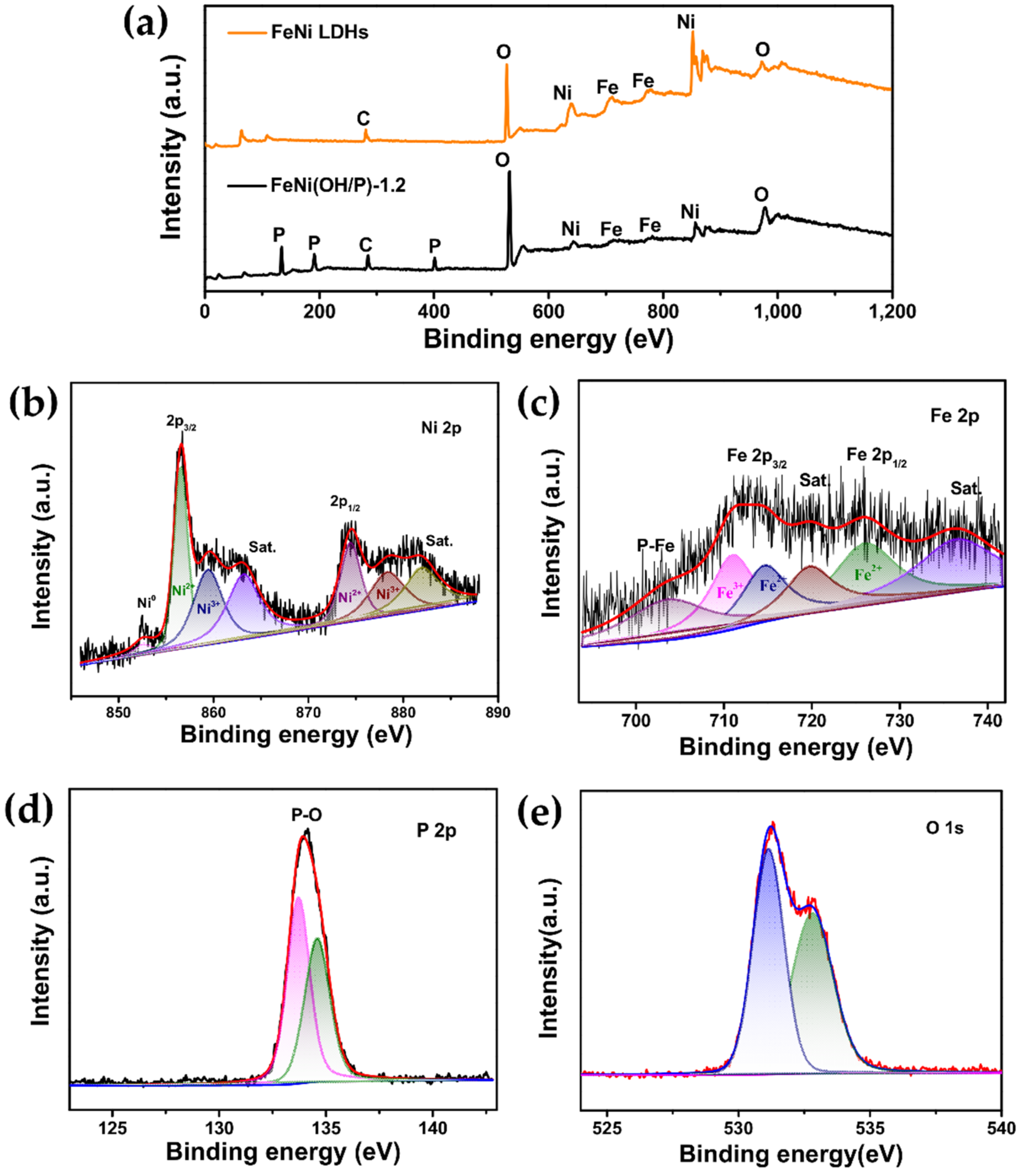
2.3. Morphology and Structure Characterization

The micromorphology and structure of the as-synthesized materials were analyzed using a scanning electron microscope (SEM, PHILIPS XL30 TMP) and transmission electron microscope (TEM, JEM-2000 UHR SETM/EDS). Energy dispersive X-ray spectroscopy (EDX), elemental mapping, and selected area electron diffraction (SAED) were performed on the same FE-TEM microscope. The phase characteristics of the as-synthesized materials were identified using X-ray diffraction (XRD) and X-ray photoelectron spectroscopy (XPS, AXIS SUPRA+). Mass weighting was recorded with a semi-micro balance (ESJ200-4B) with an accuracy of 0.01 mg.

2.4. Electrochemical Measurements

All of the electrochemical measurements (three electrodes/two electrodes) were performed using the CHI660D electrochemical workstation. The FeNi(OH/P) electrode was used directly as the working electrode, the Pt electrode (1 × 1 cm2) was used as a counter electrode, the Ag/AgCl electrode was used as the reference electrode, and the electrolyte was 3 mol L−1 KOH. The scanning rates of the cyclic voltammetry (CV) were 1~100 mV s−1 within a potential window of 0~0.45 V, and the galvanostatic charge–discharge (GCD) test range was 0~0.4 V. Electrochemical impedance spectroscopy (EIS) was tested between 0.01 Hz and 100 kHz.
The areal capacity Ca (C cm−2) was calculated from the CV curves using Equation (1):
C a = I V d V / 2 v A
The capacity Cs (C cm−2) was calculated from the GCD curves using Equation (2):
C s = 2 I V d t / Δ V
where I(V) refers to the current at V, dV is the differential potential, v is the scan rate, Δ t is the discharge time, A is the electrode’s surface area, m is the mass of active material, and Δ V is the potential window.
The HSC device was assembled using FeNi(OH/P)-1.2 as the cathode electrode and PPy/C as the anode electrode with a gel electrolyte. The charges stored between the cathode and anode electrodes were balanced (Q+ = Q−) based on the three-electrode system outcomes in order to achieve an excellent ASC device performance. According to Equation (3), the ratio of mass between FeNi(OH/P)-1.2 and PPy/C was 0.29.
m + / m = C a × Δ V / C a + × Δ V +
where the subscripts “+” and “−” represent the cathode and anode electrodes, respectively. The energy densities (E) and the power density (P) were calculated using Equations (4) and (5):
E = C × Δ V 2 / 7.2
P = E × 3600 / Δ t

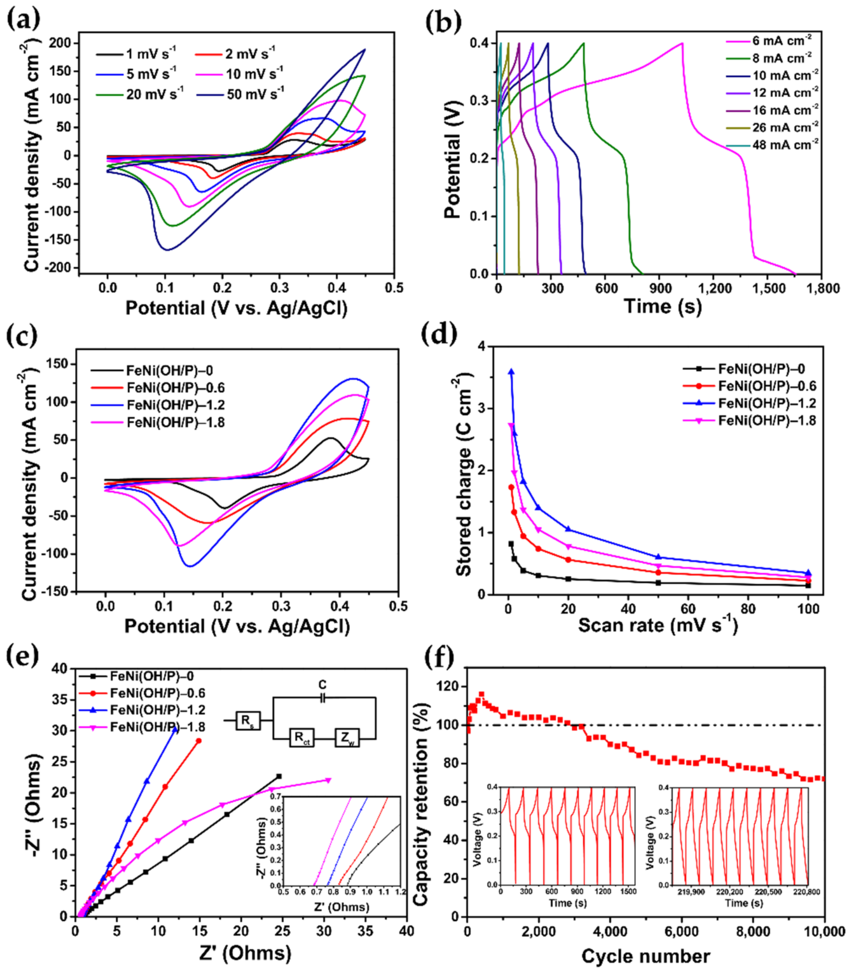
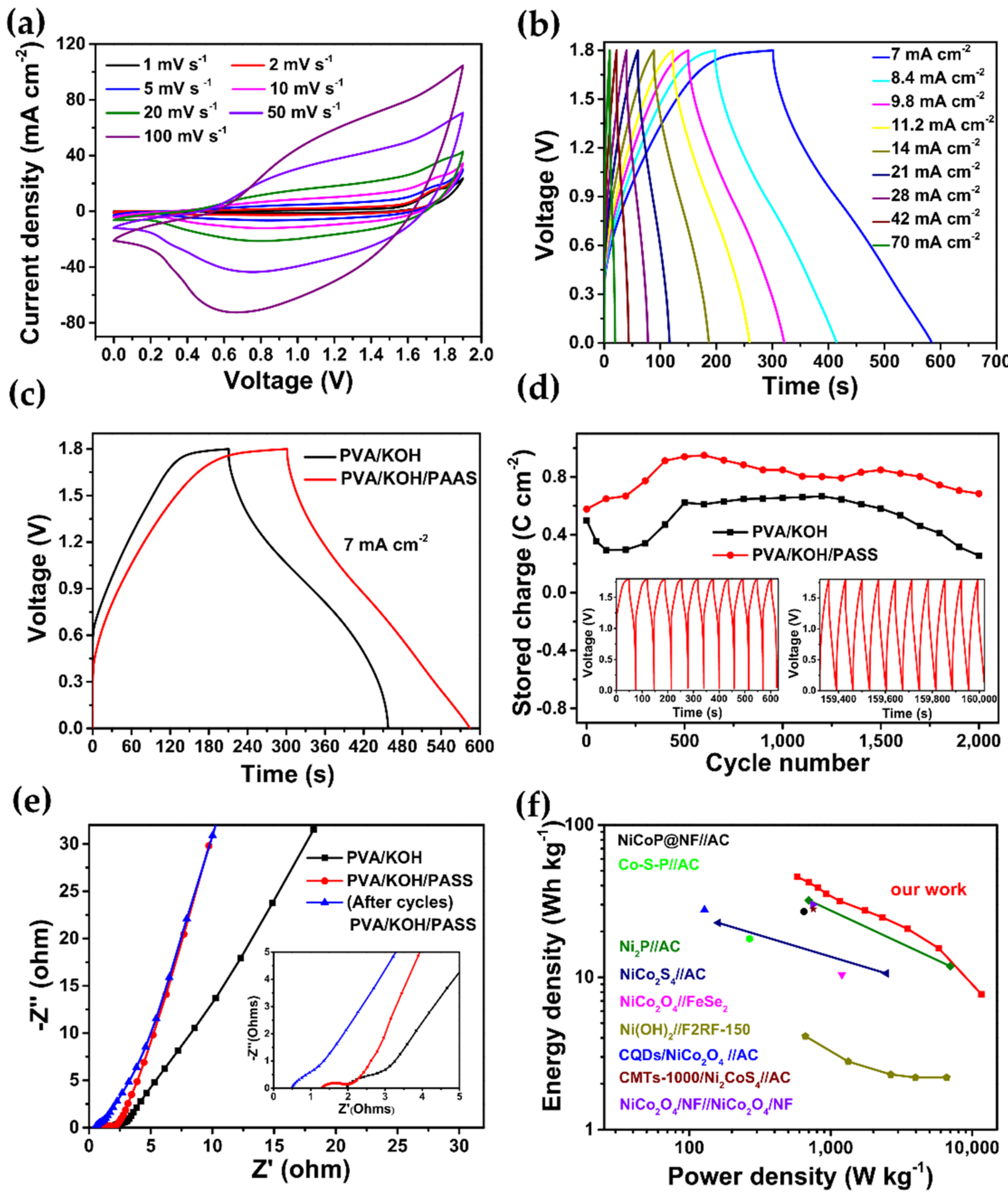
3. Results and Discussion

The synthesis process of the FeNi(OH/P)-1.2 nanosheet array on nickel foam is shown in Figure 1. First, as a 3D current collector, nickel foam (NF) with a 3D porous structure and high conductivity also provides the Ni source in the hydrothermal reaction. The honeycomb-like FeNi LDH nanosheet array was vertically grown on the 3D NF through a simple hydrothermal method (Figure 2a). Different from the traditional bimetallic co-precipitation method, the obtained FeNi LDHs grew robustly and did not fall off easily in the continuous testing work, which provided a good cycle performance. Additionally, NaCl acted as a structure directing agent, which contributed to the formation of the FeNi LDH nanosheet morphology. After heat treatment (without NaH2PO2), FeNi LDH was converted to FeNi(OH/P)-0 and the morphology remained largely unchanged (Figure S1a). After phosphating (1.2 g NaH2PO2), the color of the FeNi LDH precursor changed from orange to black, forming the FeNi(OH/P)-1.2 nanosheet array. The overall morphology of the FeNi(OH/P)-1.2 nanosheet array was maintained, which facilitated electron/ion transmission and promoted electrochemical energy storage. The surface of FeNi(OH/P)-1.8 (Figure S1c) was covered with a thick layer of phosphide and had a small number of nanotubes composed of P, and its specific surface area decreased, resulting in a reduction in the active reaction area [18].
When the phosphating reaction just occurred, P4− reacted with metal ions on the surface of the material to produce a thin film of phosphide. Further reactions depended on the diffusion rate of the metal cations inside the material. Metal cation ions are relatively small and diffuse from the inside to the outside. P4− anion ions are relatively large and diffuse from the outside to the inside. Therefore, when the reaction proceeded further, the outward diffusion of metal cations dominated, the phosphating reaction accumulated in the outer layer, and the metal phosphide shell thickened. Therefore, the morphology before and after phosphating was maintained. This was clearly evidenced in the TEM results. Figure 2d clearly shows the morphology of a single FeNi(OH/P)-1.2 nanosheet with a diameter of about 120–200 nm. The SAED (Figure 2e) presented typical diffraction rings, proving that the as-prepared FeNi(OH/P)-1.2 was polycrystalline.
Figure 2g shows the XRD patterns of FeNi(OH/P)-1.2. Three broad peaks around 44.5°, 51.8°, and 76.4° could be clearly observed in the samples, which were assigned to the (111), (200), and (220) planes of the NF, respectively. The diffraction peaks of the sample at 2θ = 44.2°, 47.2°, 54°, and 73.9° corresponded to the (201), (210), (300), and (212) crystal planes of the hexagonal Fe2P (JCPDS card no. 83-2337), respectively, while the peaks at 47.3°, 50.4°, and 88.9° were attributed to the (210), (300), and (321) planes of Ni2P (JCPDS card no. 03–0953), respectively [21]. With the increase in the phosphorus source (the mass of NaH2PO2), the diffraction peaks were sharper and stronger, indicating that more FeNiP was successfully transformed (Figure S2). It can be seen from the XRD spectrum that the intensity of the diffraction peaks was weak because of the strong base Ni peak and incomplete phosphating of the FeNi(OH/P) material obtained. However, consistent with the XRD patterns, Fe, Ni, P, and O element peaks could also clearly be found from the element mapping (Figure 2f). The Fe, Ni, P, and O elements were uniformly distributed throughout the single nanosheet, confirming the formation of the FeNi(OH/P)-1.2 material. From the EDX spectrum (Figure 2g), the atomic ratios of Ni, Fe, P, and O were 0.12:0.06:0.14:0.68, which clearly indicate the existence of incomplete phosphating.
The elemental compositions and chemical valences of the samples were then revealed using XPS. Figure 3 shows the complete scan spectrum of FeNi(OH/P)-1.2. The appearance of Ni, Fe, P, and O peaks indicates the presence of these four elements. Figure 3b is the energy spectrum of Ni 2p. The two peaks at binding energies of 874.7 and 856.7 eV corresponded to Ni 2p1/2 and Ni 2p3/2, respectively. At the same time, the two satellite peaks at 880.9 and 861.9 eV confirmed the spin-orbit characteristics of Ni2+, which is a typical feature of the combination of Ni2+ and oxygen. Note that the other peaks emerged at 852.0 eV (2p3/2), demonstrating that Ni2+ ions were partially reduced to a metallic state, and the metallic characteristics typically offered fast electron transportation, thereby enhancing the electrochemical performance [14]. Figure 4c shows the energy spectrum of Fe 2p. The binding energies of 726.2 and 711.1 eV were accompanied by satellite peaks of 720.9 and 733.7 eV, which correspond to Fe 2p1/2 and Fe 2p3/2, respectively. The peak at 704.0 eV is related to Fe-P and indicates a positively charged Fe (δ+) [19]. Figure 4d shows the energy spectrum of the P 2p element, which can be fitted to two main peaks of 134.6 and 133.8 eV, corresponding to P 2p1/2 and P 2p3/2, respectively. The formation of the P−O bond is attributed to the oxidation on the surface of the metal phosphide [22]. It can be seen from Figure 4e that O 1s can be convoluted at 530.9 and 532 eV, which indicates the existence of metal hydroxides. Based on the XPS analysis, the percentages of Fe, Ni, P, and O in these samples were 5.8%, 11.6%, 13.8%, and 58.8%, respectively, which are consistent with the EDS results. In summary, the obtained FeNi(OH/P) material consisted of FeNi LDHs and FeNiP.
According to the above XPS results, the process of in situ growth of FeNi LDHs can be speculated. In the hydrothermal process, Fe3+ produced a redox attack on the NF and released Ni2+ on the surface of the NF, because E F e 3 + / F e 2 + 0 (0.771 V) was much higher than E N i 3 + / N i 2 + 0 (−0.257 V). In addition, as a result of the presence of oxygen, Fe2+ was oxidized to Fe3+. Finally, Ni2+ and Fe3+ ions easily reacted with OH to form FeNi LDHs on the NF [23]. The equations used above are as follows:
2 F e 3 + + N i = 2 F e 2 + + N i 2 +
4 F e 2 + + O 2 + 2 H 2 O = 4 F e 3 + + 4 O H
N i 2 + + F e 3 + + O H = N i F e O H x
NaCl as a structure directing agent did not participate in the formation of hydrothermal products. This was because the ionic radius of Na+ (1.02 Å) [24] was significantly larger than those of Fe3+ (0.65 Å) and Ni2+ (0.69 Å), and LDHs usually consist of both divalent and trivalent cations [25]. Most notably, unlike the traditional bimetallic coprecipitation method, in situ grown interconnected FeNi nanosheet arrays are firmly attached to the NF, accompanied by ferric salts as catalysts, which gives the electrode materials excellent stability.
The electrochemical properties of the as-synthesized samples were first investigated in a three-electrode system using a 3.0 M KOH electrolyte. As shown in Figure 4a, CV tests of the FeNi(OH/P)-1.2 electrode between 0~0.45 V were obtained at 1~100 mV s−1. As the scan rate increased, the closed area of the CV curve also increased, the response peak current also increased, and a faster redox reaction occurred. The peaks shifted towards a higher and lower potential, respectively. Two redox peaks were clearly observed on all CV curves, which demonstrated the characteristic battery-type behavior of the electrodes. This could be related to the highly reversible Faradaic reactions between Ni+/Ni2+ and hydroxyl anions, as well as between Fe2+/Fe3+ and hydroxyl anions. The possible redox reactions for the FeNi(OH/P) electrode involved in the KOH electrolyte can be summarized using Equations (9)–(11), as follows:
F e N i P + 2 O H N i P x O H + F e P x O H + 2 e
F e P x O H + O H F e P x O + H 2 O + e
N i P x O H + O H N i P x O + H 2 O + e
The chemical process of Equation (9) is related to the oxidation of TMP, and Equations (10) and (11) are related to the adsorption−desorption of OH ions. The adsorption capacity of the OH ions between the active material and the electrolyte affects the electrochemical performance of the electrode.
Figure 4b depicts the GCD curves of the FeNi(OH/P)-1.2 electrode at different current densities. There is an obvious platform in the discharge curve, indicating a more battery-type redox behavior, consistent with the CV curve results. The charging time was almost equal to the discharging time at all current densities, indicating that FeNi(OH/P)-1.2 has Coulombic efficiency and highly reversible redox reactions in GCD. The Cs of FeNi(OH/P)-1.2 was calculated to be 2740.9, 2393.0, 2196.6, 2045.0, 1649.9, and 1025.0 mC cm−2 at current densities of 6, 8, 10, 12, 26, and 48 mA cm−2, respectively.
Figure S3a depicts the CV plots of the obtained FeNi LDHs and FeNi(OH/P)-1.2 electrode for 0~0.45 V. Notably, the FeNi(OH/P)-1.2 electrode demonstrates the larger CV area and peak current density. The capacities (Figure S3b) were then calculated from the CV curves. Compared with the FeNi LDH electrode, the FeNi(OH/P)-1.2 electrode had a better rate performance, which indicates significantly improved electrochemical activities and an enhanced capacity of phosphide samples. Figure 4c shows the CV curves of the obtained FeNi(OH/P)-0, FeNi(OH/P)-0.6, FeNi(OH/P)-1.2, and FeNi(OH/P)-1.8 electrodes at a scan rate of 20 mV s−1. All of the curves exhibited similar pairs of redox peaks. To learn more about this, Figure 4d displays the rate performance for the FeNi(OH/P) electrode with different amounts of NaH2PO2. The result indicates that the FeNi(OH/P)-1.2 electrode demonstrated the highest specific capacity and best rate performance out of all of the as-prepared electrodes. Specifically, the FeNi(OH/P)-1.2 electrode possessed a specific capacity of up to 3.6 C cm−2 at 1 mV s−1. This capacitive value was higher than that of the FeNi LDH electrode (1.0 C cm−2), FeNi(OH/P)-0 electrode (0.82 C cm−2), and FeNi(OH/P)-0.6 electrode (1.7 C cm−2) at 1 mV s−1. When the addition of NaH2PO2 was 1.8 g, the capacity of the FeNi(OH/P)-1.8 electrode decreased (2.7 C cm−2 at 1 mV s−1) compared with FeNi(OH/P)-1.2, indicating that phosphorus-rich TMPs had a lower specific capacity as a result of electron accumulation around the P atoms. The highest capacity obtained of 3.6 C cm−2 (≈1469.9 C g−1 and 408.3 mAh g−2) at 1 mV s−1 was excellent compared with the reported metal phosphide electrodes.
To better explain the electrochemical properties, we need to clarify the electrochemical kinetics of the FeNi(OH/P) electrodes, which have two energy storage mechanisms: Faradaic and non-Faradaic reactions. The non-Faradaic reaction is the process of electrostatic adsorption in electric double-layer capacitors. In contrast, Faradaic reactions occur on both the surface (redox pseudocapacitance) and in the bulk of the material (typically as in conventional batteries; diffusion-controlled).
The capacitive effects can be characterized by analyzing the CV data at various sweep rates according to the following [26,27]:
i = a v b
where i is the current, ν is the scan rate, and a and b are constants. Here, b is determined from the slope of the plot of log i versus log v according to Equation (12). When b is close to 1, this indicates that it is predominantly capacitive. When b is equal to 0.5, this means that this is a diffusion-controlled process. The calculated b values for the FeNi(OH/P) electrodes are shown in Figure S4. It was found that the b value for all of the FeNi(OH/P) electrodes with different amounts of NaH2PO2 was always around 0.5, indicating that the current comes primarily from the diffusion-controlled process. This manifests the battery-type behavior of the FeNi(OH/P) electrode.
To further study the ion and electron transport kinetics of the FeNi(OH/P) electrodes, electrochemical impedance spectroscopy (EIS) measurements with equivalent circuits are shown in Figure 4e. The impedance spectra are composed of one semicircle and a linear segment in the high- and low-frequency region, respectively. The intercept at the real axis represents the equivalent series resistance (Rs), which is a combination of ionic resistance of the electrolytes, electronic resistance of the electrode materials, and interface resistance. The values of Rs for FeNi(OH/P)-0, FeNi(OH/P)-0.6, FeNi(OH/P)-1.2, and FeNi(OH/P)-1.8 are 0.88, 0.83, 0.76, and 0.68 Ω, respectively. As the content of NaH2PO2 increases, the R value decreases, demonstrating improved charge-transfer kinetics and rapid electron transport for redox reactions after phosphating. However, the FeNi(OH/P)-1.8 electrodes with the lowest slope in the low-frequency region demonstrate its higher diffusive resistance. Ion diffusion is affected because of the accumulation of electrons around the P atoms in the P-rich TMPs.
Figure 4f reveals the cycle performance of the FeNi(OH/P)-1.2 electrodes. After 10,000 cycles of GCD curves at 24 mA cm−2, the capacitive retention of the FeNi(OH/P)-1.2 electrode was 72.0% and remained unchanged. The increase in capacity during the first 600 cycles could be attributed to the activation of FeNi(OH/P), which conformed with the characteristics of Ni(OH)2 [20] and NiP [18], indicating that they had standard metalloid characteristics. The diminishment of the capacity performance could be attributed to the following: (1) the formation of FeNi hydroxide from the surface of FeNi(OH/P) reacting with the electrolyte [28]. (2) In FeNi compounds, Ni was the active site for Faradaic reactions and it was easier to convert Ni2+ to Ni3+, but not in the reverse process. After multiple charge/discharge processes, the irreversible reaction of Ni2+ increased, so the Faraday capacitance became lower and lower [9,29]. A detailed comparison between the electrochemical properties reported in the present study and in previously reported studies for composites in a three-electrode system is given in Table 1.
It can be observed that the addition of NaH2PO2 in phosphating had a significant effect on the electrochemical performance of the as-prepared samples. This may be because of the following: (1) When the mass of NaH2PO2 was less than 1.2 g, there was no morphology change compared with the precursor, and the phosphating degree of the precursor was insufficient, resulting in insufficient active sites during the electrochemical reaction. (2) When the mass of NaH2PO2 was more than 1.2 g, the porosity decreased obviously owing to the aggregation of phosphide as a thick layer, resulting in a decrease in the specific surface area and ion/electron transport channels. Moreover, phosphorus-rich metal phosphides have a large number of P–P bonds, leading to free electron clusters and a reduced electrochemical performance. Therefore, when the addition of NaH2PO2 was 1.2 g, saturation phosphorization and nanostructure optimization of the as-prepared samples were achieved simultaneously. More importantly, the electrochemical performance was also optimized at the same time.
To further demonstrate the practical feasibility of the optimized FeNi(OH/P) electrode, an all-solid-state hybrid supercapacitor (HSC) was assembled with FeNi(OH/P)-1.2 as the cathode electrode and PPy/C as the anode electrode. Figure S5a displays the SEM image of the PPy/C anode, which is composed of a PPy/C nanorod. The XRD pattern is shown in Figure S3b. The diffraction peaks around 24° and 43° could be indexed to the (002) and (100) crystal planes of the carbon, respectively. The CV curves of the PPy/C electrode and FeNi(OH/P)-1.2 electrode at 20 mV s−1 are displayed in Figure S6a. The rectangular CV curve of the PPy/C anode reveals the electrical double-layer capacitance (EDLC) behavior, which is different from the electrochemical feature of the FeNi(OH/P) cathode. Figure 5a shows that the hybrid supercapacitor can work efficiently in a large operating voltage for 1.9 V. The GCD curves of the HSC at various current densities from 7 to 140 A cm−2 displayed an almost symmetrical triangular shape with a slight deviation, indicating its good electrochemical reversibility and ideal capacitance behavior (Figure 5b). Notably, the HSC reached 1.9 C cm−2, 1.4 C cm−2, 0.7 C cm−2, and 0.3 C cm−2 at 7 mA cm−2, 14 mA cm−2, 70 mA cm−2, and 140 mA cm−2, respectively.
To study the influence of PAAS on electrolytes, we evaluated the electrochemical performance of the HSC with different gel electrolytes using the same electrodes. From the GCD curves (Figure 5a and Figure S6b), the HSC with PAAS had a longer discharge time. These results indicated the enhanced charge storage capacity of the FeNi(OH/P)//AC HSC after optimizing the electrolyte. As shown in Figure 5d, 2000 cycles were tested at 21 mA cm−2. Impressively, after 2000 cycles, the capacity retention of the HSC with PAAS remained at 118.5%, which was better than the HSC without PAAS (51.3%). Sodium polyacrylate (PAAS) is a polyanionic electrolyte with good water solubility and a large number of hydrophilic groups [42]. Its aqueous solution has a good dissociation, wettability, and water retention. When added to the PVA/KOH electrolyte, it not only has good film-forming properties to encapsulate the two electrodes, but can also retain the water in the electrolyte well so as to reduce the water loss of the electrolyte and affect the electrochemical performance during electrochemical work. Moreover, PAAS is also a surfactant that can prevent the negative effect of metal ions. It can ameliorate the redox activity of battery-type electrodes and catalyze the reaction of the active material with OH. According to the above experimental results, PAAS, as a water-retaining agent/active agent in the electrolyte, can greatly improve the cycle performance of solid-state energy storage devices. The capacity retention of the HSC with PAAS is far superior to the reported supercapacitor; for instance, NiCoP@NF//AC (67.2%, 500 cycles) [31], NiCo2O4//FeSe2 (90%, 1000 cycles) [43], CQDs/NiCo2O4//AC (101.9%, 5000 cycles) [44], NiCo2S4//C (76%, 5000 cycles) [45], and NiCo2O4/NF//NiCo2O4/NF (86%, 500 cycles) [46].
The kinetic factors for the enhanced electrochemical performance were analyzed using EIS spectra (Figure 5e). The electrolyte resistances (Rs) of the HSC with PAAS (Rs = 1.3 Ω) were smaller than those of the HSC without PAAS (Rs = 2.1 Ω), and the charge transfer resistance (Rct) of the HSC with PAAS (Rct = 0.7 Ω) was smaller than that of the HSC without PAAS (Rs = 1.06 Ω), indicating a fast electron transfer ability. Meanwhile, the slope of the HSC with PAAS in the low-frequency region was larger than that of the HSC without PAAS; thus, its ion diffusion kinetics were enhanced through the addition of PAAS in the electrolyte, which is consistent with the CV/GCD results. Furthermore, it can be seen that the Rs and Rct of the HSC with PAAS (Rs = 0.5 Ω, Rct = 0.61 Ω) were smaller after the cycles.
The Ragone plots of the HSC in this research are compared with the reported literature in Figure 5f. The HSC exhibited a high energy density of 45 Wh kg−1 at 581 W kg−1, which is superior to that reported in the literature, such as NiCoP@NF//AC (27 Wh kg−1 at 647 W kg−1) [31], CQDs/NiCo2O4//AC (27.8 Wh kg−1 at 128 W kg−1) [44], NiCo2O4//FeSe2 (10.4 Wh kg−1 at 1200 W kg−1) [43], NiCoP (30.2 Wh kg−1 at 891 W kg−1) [27], NiCo2S4//C (22.8 Wh kg−1 at 160 W kg−1) [45], NiCo2O4/NF//NiCo2O4/NF (30 Wh kg−1 at 750 W kg−1) [46], Co-S-P//AC (17.9 Wh kg−1 at 750 W kg−1) [47], CMTs-1000/Ni2CoS4//AC (28.1 Wh kg−1 at 753 W kg−1) [48], and Ni(OH)2//F2RF-150 (4.1 Wh kg−1 at 661.5 W kg−1) [49].

4. Conclusions

In summary, a self-supported nanohoneycomb (NHC)-like FeNi(OH/P) nanosheet array was prepared through a simple two-step procedure. By adjusting the addition of NaH2PO2, the FeNi(OH/P) electrode simultaneously achieved saturation phosphorization and nanostructure optimization. The as-fabricated FeNi(OH/P) electrode achieved a significantly enhanced specific capacity of 3.6 C cm−2 (≈408.3 mAh g−1) at 1 mV s−1 with cyclic stability (72.0% retention after 10,000 cycles). Meanwhile, an all-solid-state hybrid supercapacitor device assembled by employing FeNi(OH/P) as the cathode electrode and PPy/C as the anode electrode exhibited a high capacity of 1.9 C cm−2 at 7 mA cm−2, a maximum energy density of 45 Wh kg−1, and excellent cyclic stability of 118.5% after 2000 cycles after optimizing the electrolyte. These excellent properties indicate that the FeNi(OH/P) nanosheet array has excellent prospects as an advanced electrode material for HSCs.

Supplementary Materials

The following supporting information can be downloaded at: https://www.mdpi.com/article/10.3390/en15113877/s1. Figure S1: SEM images of (a) FeNi(OH/P)-0, (b) FeNi(OH/P)-0.6, and (c) FeNi(OH/P)-1.8. Figure S2: Comparison of the XRD pattern for FeNi(OH/P) with different amount ofNaH2PO2. Figure S3: Comparison of (a) CV curves and (b) rate performance of FeNi LDHs and the FeNi(OH/P)-1.2 electrode. Figure S4: The value of b for FeNi(OH/P) electrodes with different amounts of NaH2PO2. Figure S5: (a) SEM images and (b) XRD pattern of the PPy/C. The inset of (a) shows SEM image of the PPy/C under high magnifications. Figure S6: (a) CV curves of the FeNi(OH/P)-1.2 cathode and PPy/C anode performed in 3 M KOH. (b) Comparison of the rate performance capacity for FeNi(OH/P)//PPy/C HSC with different electrolytes.

Author Contributions

Writing—original draft preparation, C.L.; formal analysis and data curation, C.L.; writing—review and editing, R.L.; supervision and funding acquisition, Y.Z. All authors have read and agreed to the published version of the manuscript.

Funding

This research was funded by the National Natural Science Foundation of China (no. 51802233) and the Natural Science Foundation of Hubei Province of China (no. 2018CFB154).

Institutional Review Board Statement

Not applicable.

Informed Consent Statement

Not applicable.

Data Availability Statement

Not applicable.

Conflicts of Interest

The authors declare no conflict of interest.

References

  1. Gui, Q.; Ba, D.; Li, L.; Liu, W.; Li, Y.; Liu, J. Recent advances in materials and device technologies for aqueous hybrid supercapacitors. Sci. China Mater. 2022, 65, 10–31. [Google Scholar] [CrossRef]
  2. Zuo, W.; Li, R.; Zhou, C.; Li, Y.; Xia, J.; Liu, J. Battery-Supercapacitor hybrid devices: Cecent progress and future prospects. Adv. Sci. 2017, 7, 1600539. [Google Scholar] [CrossRef] [PubMed]
  3. Theerthagiri, J.; Murthy, A.P.; Lee, S.J.; Karuppasamy, K.; Arumugam, S.R.; Yu, Y.; Hanafiah, M.M.; Kim, H.; Mittal, V.; Choi, M.Y. Recent progress on synthetic strategies and applications of transition metal phosphides in energy storage and conversion. Ceram. Int. 2020, 47, 4404–4425. [Google Scholar] [CrossRef]
  4. Zong, Q.; Liu, C.; Yang, H.; Zhang, Q.; Cao, G. Tailoring nanostructured transition metal phosphides for high-performance hybrid supercapacitors. Nano Today 2021, 38, 101201. [Google Scholar] [CrossRef]
  5. Oyama, S.T.; Clark, P.; Wang, X.; Shido, T.; Iwasawa, Y.; Hayashi, S.; Ramallo-López, J.M.; Requejo, F.G. Structural characterization of tungsten phosphide (WP) hydrotreating catalysts by X-ray absorption spectroscopy and nuclear magnetic resonance spectroscopy. J. Phys. Chem. B 2002, 106, 1913–1920. [Google Scholar] [CrossRef]
  6. Agarwal, A.; Sankapal, B.R. Metal phosphides: Topical advances in the design of supercapacitors. J. Mater. Chem. A 2021, 9, 20241–20276. [Google Scholar] [CrossRef]
  7. Sun, M.; Liu, H.; Qu, J.; Li, J. Earth-Rich transition metal phosphide for energy conversion and storage. Adv. Energy Mater. 2016, 6, 1600087. [Google Scholar] [CrossRef]
  8. Lu, Y.; Jiang, B.; Fang, L.; Ling, F.; Wu, F.; Hu, B.; Meng, F.; Niu, K.; Lin, F.; Zheng, H. An investigation of ultrathin nickel-iron layered double hydroxide nanosheets grown on nickel foam for high-performance supercapacitor electrodes. J. Alloys Compd. 2017, 714, 63–70. [Google Scholar] [CrossRef]
  9. Li, M.; Jijie, R.; Barras, A.; Roussel, P.; Szunerits, S.; Boukherroub, R. NiFe layered double hydroxide electrodeposited on Ni foam coated with reduced graphene oxide for high-performance supercapacitors. Electrochim. Acta 2019, 302, 1–9. [Google Scholar] [CrossRef]
  10. Chen, C.; Dong, C.; Wang, B.; Huang, J.; Wang, Y. Synthesis and room temperature ferromagnetism in Fe-doped CuAlO2 semiconductor. J. Wuhan Univ. Technol. Mater. Sci. Ed. 2013, 28, 500–503. [Google Scholar] [CrossRef]
  11. Varshney, D.; Kumar, A. Structural and optical properties of Ni substituted CaCu3Ti4-xNixO12. Opt. Int. J. Light Electron Opt. 2015, 126, 3437–3441. [Google Scholar] [CrossRef]
  12. Verma, S.; Arya, S.; Gupta, V.; Mahajan, S.; Furukawa, H.; Khosla, A. Performance analysis, challenges and future perspectives of nickel based nanostructured electrodes for electrochemical supercapacitors. J. Mater. Res. Technol. 2021, 11, 564–599. [Google Scholar] [CrossRef]
  13. Ma, L.; Sun, Y.; Guo, J. NiFeP nanocubes as advanced electrode material for hydrogen evolution and supercapacitor. Colloid Interface Sci. Commun. 2021, 45, 100520. [Google Scholar] [CrossRef]
  14. Xiao, C.; Zhang, B.; Li, D. Partial-sacrificial-template Synthesis of Fe/Ni Phosphides on Ni Foam: A Strongly Stabilized and Efficient Catalyst for Electrochemical Water Splitting. Electrochim. Acta 2017, 242, 260–267. [Google Scholar] [CrossRef]
  15. Liang, H.; Gandi, A.N.; Xia, C.; Hedhili, M.H.; Anjum, D.; Schwingenschlögl, U.N.; Alshareef, H. Amorphous NiFe-OH/NiFeP electrocatalyst fabricated at low temperature for water oxidation applications. ACS Energy Lett. 2017, 2, 1035–1042. [Google Scholar] [CrossRef]
  16. Lv, Z.; Wang, K.; Si, Y.; Li, Z.; Jiang, L. High performance of multi-layered alternating Ni-Fe-P and Co-P films for hydrogen evolution. Green Energy Environ. 2020, 7, 75–85. [Google Scholar] [CrossRef]
  17. Baasanjav, E.; Bandyopadhyay, P.; Saeed, G.; Lim, S.; Jeong, S.M. Dual-ligand modulation approach for improving supercapacitive performance of hierarchical zinc–nickel–iron phosphide nanosheet-based electrode. J. Ind. Eng. Chem. 2021, 99, 299–308. [Google Scholar] [CrossRef]
  18. Zhang, S.; Yang, Y.; Tang, Y.; Chi, L.; Xu, B. Synthesis and electrochemical properties of high-activity Fe2O3@Ni composite electrode. Inorg. Chem. Ind. 2019, 51, 24–27. [Google Scholar]
  19. Pan, C.; Liu, Z.; Huang, M. 2D iron-doped nickel MOF nanosheets grown on nickel foam for highly efficient oxygen evolution reaction. Appl. Surf. Sci. 2020, 529, 147201. [Google Scholar] [CrossRef]
  20. Zhang, C.; Ma, B.; Zhou, Y. Three-dimensional polypyrrole derived N-doped carbon nanotube aerogel as a high performance metal free catalyst for oxygen reduction reaction. ChemCatChem 2019, 11, 5495–5504. [Google Scholar] [CrossRef]
  21. Zhou, K.; Zhou, W.; Yang, L.; Lu, J.; Cheng, S.; Mai, W.; Tang, Z.; Li, L.; Chen, S. Ultrahigh-performance pseudocapacitor electrodes based on transition metal phosphide nanosheets array via phosphorization: A general and effective approach. Adv. Funct. Mater. 2015, 25, 7530–7538. [Google Scholar] [CrossRef]
  22. Qu, M.; Jiang, Y.; Yang, M.; Liu, S.; Guo, Q.; Shen, W.; Li, M.; He, R. Regulating electron density of NiFe-P nanosheets electrocatalysts by a trifle of Ru for high-efficient overall water splitting. Appl. Catal. B Environ. 2020, 263, 118324. [Google Scholar] [CrossRef]
  23. Li, J.; Lian, R.; Wang, J.; He, S.; Rui, Z. Oxygen vacancy defects modulated electrocatalytic activity of iron-nickel layered double hydroxide on Ni foam as highly active electrodes for oxygen evolution reaction. Electrochim. Acta 2019, 331, 135395. [Google Scholar] [CrossRef]
  24. Luo, W.; Dahn, J.R. Preparation of Co1−zAlz(OH)2(NO3)z Layered Double Hydroxides and Li(Co1−zAlz)O2. Chem. Mater. 2009, 21, 56–62. [Google Scholar] [CrossRef]
  25. Wang, Q.; O’Hare, D. Recent advances in the synthesis and application of layered double hydroxide (LDH) nanosheets. Chem. Rev. 2012, 112, 4124–4155. [Google Scholar] [CrossRef]
  26. Gogotsi, Y.; Penner, R.M. Energy Storage in Nanomaterials—Capacitive, Pseudocapacitive, or Battery-like? ACS Nano 2018, 12, 2081–2083. [Google Scholar] [CrossRef] [Green Version]
  27. Okhay, O.; Tkach, A. Graphene/Reduced Graphene Oxide-Carbon Nanotubes Composite Electrodes: From Capacitive to Battery-Type Behaviour. Nanomaterials 2021, 11, 1240. [Google Scholar] [CrossRef]
  28. Ji, J.; Zhang, L.L.; Ji, H.; Li, Y.; Zhao, X.; Bai, X.; Fan, X.; Zhang, F.; Ruoff, R.S. Nanoporous Ni(OH)2 thin film on 3D ultrathin-graphite foam for asymmetric supercapacitor. Acs Nano 2013, 7, 6237–6243. [Google Scholar] [CrossRef]
  29. Zhao, Y.; Zhao, M.; Ding, X.; Liu, Z.; Qiao, L. One-step colloid fabrication of nickel phosphides nanoplate/nickel foam hybrid electrode for high-performance asymmetric supercapacitors. Chem. Eng. J. 2019, 373, 1132–1143. [Google Scholar] [CrossRef]
  30. Wan, L.; Wang, Y.; Zhang, Y.; Du, C.; Xie, M. FeCoP nanosheets@Ni-Co carbonate hydroxide nanoneedles as free-standing electrode material for hybrid supercapacitors. Chem. Eng. J. 2021, 415, 128995. [Google Scholar] [CrossRef]
  31. Wan, L.; Chen, D.; Liu, J.; Zhang, Y.; Du, C. Construction of FeNiP@CoNi-layered double hydroxide hybrid nanosheets on carbon cloth for high energy asymmetric supercapacitors. J. Power Sources 2020, 465, 228293. [Google Scholar] [CrossRef]
  32. Wan, L.; He, C.; Chen, D.; Liu, J.; Chen, J. In situ grown NiFeP@NiCo2S4 nanosheet arrays on carbon cloth for asymmetric supercapacitors. Chem. Eng. J. 2020, 399, 125778. [Google Scholar] [CrossRef]
  33. Shuai, M.; Lin, J.; Wu, W.; Kuang, H.; Zhang, W.; Ling, Q.; Chen, H.; Komarneni, S. Metallic nickel–cobalt phosphide/multilayer graphene composite for high-performance supercapacitors. New J. Chem. 2020, 44, 8796–8804. [Google Scholar] [CrossRef]
  34. He, S.; Li, Z.; Mi, H.; Ji, C.; Qiu, J. 3D nickel-cobalt phosphide heterostructure for high-performance solid-state hybrid supercapacitors. J. Power Sources 2020, 467, 228324. [Google Scholar] [CrossRef]
  35. Parveen, N.; Hilal, M.; Han, J.I. Newly design porous/sponge red phosphorus@graphene and highly conductive Ni2P electrode for asymmetric solid state supercapacitive device with excellent performance. Nano Micro Lett. 2020, 12, 1–16. [Google Scholar] [CrossRef] [PubMed] [Green Version]
  36. Wang, Z.; Chen, F.; Kannan, P.; Ji, S.; Wang, H. Nickel phosphate nanowires directly grown on Ni foam as binder-free electrode for pseudocapacitors. Mater. Lett. 2019, 257, 126742. [Google Scholar] [CrossRef]
  37. Zhou, C.; Gao, T.; Wang, Y.; Liu, Q.; Xiao, D. Through a hydrothermal phosphatization method synthesized NiCo and Fe-based electrodes for high-performance battery-supercapacitor hybrid device. Appl. Surf. Sci. 2019, 475, 729–739. [Google Scholar] [CrossRef]
  38. Quan, Z.; Hui, Y.; Wang, Q.; Zhang, Q.; Shen, Q. NiCo2O4/NiCoP nanoflake-nanowire arrays: A homogeneous hetero-structure for high performance asymmetric hybrid supercapacitors. Dalton Trans. 2018, 47, 16320–16328. [Google Scholar]
  39. Yong, Y.; Zhao, H.; Zong, Y.; Li, X.; Sun, Y.; Feng, J.; Wang, Y.; Zheng, X.; Du, Y. Phosphorization boosts the capacitance of mixed metal nanosheet arrays for high performance supercapacitor electrodes. Nanoscale 2018, 10, 11775–11781. [Google Scholar]
  40. Shi, F.; Xie, D.; Zhong, Y.; Wang, D.H.; Xia, X.H.; Gu, C.D.; Wang, X.L.; Tu, J.P. Facile synthesis of self-supported Ni2P nanosheet@Ni sponge composite for high-rate battery. J. Power Sources 2016, 328, 405–412. [Google Scholar] [CrossRef]
  41. Bandgar, S.B.; Vadiyar, M.M.; Jambhale, C.L.; Ye, Z.; Kolekar, S.S. Construction of dual metal ferrite-based core-shell nanostructures as low-cost multimetal electrode for boosting energy density of flexible asymmetric supercapattery. J. Energy Storage 2021, 36, 102379. [Google Scholar] [CrossRef]
  42. Liu, M.; Guo, T. Preparation and swelling properties of crosslinked sodium polyacrylate. J. Appl. Polym. Sci. 2010, 82, 1515–1520. [Google Scholar] [CrossRef]
  43. Ji, C.; Liu, F.; Xu, L.; Yang, S. Urchin-like NiCO2O4 hollow microspheres and FeSe2 micro-snowflakes for flexible solid-state asymmetric supercapacitors. J. Mater. Chem. A Mater. Energy Sustain. 2017, 5, 5568–5576. [Google Scholar] [CrossRef]
  44. Zhu, Y.; Wu, Z.; Jing, M.; Hou, H.; Ji, X. Porous NiCo2O4 spheres tuned through carbon quantum dots utilised as advanced materials for an asymmetric supercapacitor. J. Mater. Chem. A 2014, 3, 866–877. [Google Scholar] [CrossRef]
  45. Kong, W.; Lu, C.; Zhang, W.; Pu, J.; Wang, Z. Homogeneous core-shell NiCo2S4 nanostructures supported on nickel foam for supercapacitors. J. Mater. Chem. A 2015, 3, 12452–12460. [Google Scholar] [CrossRef]
  46. Cao, Z.; Liu, C.; Huang, Y.; Gao, Y.; Wang, Y.; Li, Z.; Yan, Y.; Zhang, M. Oxygen-vacancy-rich NiCo2O4 nanoneedles electrode with poor crystallinity for high energy density all-solid-state symmetric supercapacitors. J. Power Sources 2020, 449, 227571. [Google Scholar] [CrossRef]
  47. Zhao, X.; Zhu, J.; Lu, Y.; Zhang, Z.; Hong, Y.; Wang, W.; Karimov, K.; Murtaza, I.; Wang, Q.; Dong, X. Three-dimensional Co–S–P nanoflowers as highly stable electrode materials for asymmetric supercapacitors. ACS Sustain. Chem. Eng. 2019, 7, 11448–11454. [Google Scholar] [CrossRef]
  48. Wang, K.; Yan, R.; Tian, X.; Wang, Y.; Lei, S.; Li, X.; Yang, T.; Wang, X.; Song, Y.; Liu, Y.; et al. Multi-scale biomass-based carbon microtubes decorated with Ni-Co sulphides nanoparticles for supercapacitors with high rate performance. Electrochim. Acta 2019, 302, 78–91. [Google Scholar] [CrossRef]
  49. Zhao, C.; Shao, X.; Zhang, Y.; Qian, X. Fe2O3/RGO/Fe3O4 composite in-situ grown on Fe foil for high performance supercapacitors. ACS Appl. Mater. Interfaces 2016, 8, 30133–30142. [Google Scholar] [CrossRef]
Figure 1. The synthesis procedure of the FeNi(OH/P)-1.2 nanosheet array on nickel foam. The inset shows the corresponding SEM images.
Energies 15 03877 g001
Figure 2. SEM images of (a,b) FeNi LDH nanosheet arrays and (c) a FeNi(OH/P)-1.2 nanosheet array. Inset (a) shows the SEM image of the FeNi LDH nanosheet array under low magnification. (d) TEM image; (e) SAED pattern; (f) the elements mapping of Fe, Ni, P, and O; (g) XRD pattern; and (h) EDX spectrum of the FeNi(OH/P)-1.2 nanosheet array. Inset of (h) shows the corresponding atomic/weight percentages of different elements: Fe, Ni, P, and O.
Energies 15 03877 g002
Figure 3. (a) Comparison of the XPS spectra for the FeNi LDH nanosheet array and FeNi(OH/P)-1.2 nanosheet array. (b) Ni 2p, (c) Fe 2p, (d) P 2p, and (e) O 1s XPS spectra of the FeNi(OH/P)-1.2 nanosheet array.
Energies 15 03877 g003
Figure 4. (a) CV curves at different scan rates and (b) GCD curves at different current densities for the FeNi(OH/P)-1.2 electrode. Comparison of (c) CV curves, (d) rate performance, and (e) EIS spectra for FeNi(OH/P) electrodes with different amount of NaH2PO2. The inset of (e) shows the equivalent circuit diagram. (f) Cycling performance of the FeNi(OH/P)-1.2 electrode; the inset of (f) shows the first 10 cycles and the last 10 cycles of the GCD curves of the FeNi(OH/P)-1.2. electrode at 24 mA cm−2.
Energies 15 03877 g004
Figure 5. (a) CV curves and (b) GCD curves of the FeNi(OH/P)//PPy/C HSC with the PVA/KOH/PAAS gel electrolyte. Comparison of (c) GCD curves and (d) cycling performances of the FeNi(OH/P)//PPy/C HSC with different electrolytes. The inset of (d) shows the first 10 cycles and last 10 cycles of GCD curves of the FeNi(OH/P)//PPy/C HSC with PVA/KOH/PAAS gel electrolyte at 21 mA cm−2. (e) EIS spectra for the FeNi(OH/P)//PPy HSC with PVA/KOH gel electrolyte, and the FeNi(OH/P)//PPy/C HSC with the PVA/KOH/PASS gel electrolyte before and after 2000 cycles. (f) Ragone plot.
Energies 15 03877 g005
Table 1. Comparison of the electrochemical performances between the as-fabricated FeNi(OH/P) electrode and previously reported FeNi-based/TMP electrodes.
Electrode MaterialsCurrent CollectorElectrolyteSpecific
Capacitance
Capacitance
Retention
Year Ref.
ZnNiFe(OH/P) nanosheetNickel foam3 M KOH1708 F g−1/5.64 F cm−2 (1 A g−1)83%
(4000)
2021 [17]
FeCoP@NiCo nanosheetCarbon foam2 M KOH795.5 C g−1 (1 A g−1)89.7%
(5000)
2021 [30]
FeNiP@CoNi LDHs nanosheetNickel foam3 M KOH2280 F g−1 (1 A g−1)70%
(5000)
2020 [31]
NiFeP@NiCo2S4 nanosheetCarbon cloth2 M KOH874.4 C g−1 (1 A g−1)85.6%
(5000)
2020 [32]
NiCoP-MLG nanosheet (powder)-3 M KOH1419.6 F g−1 (1 A g−1)91%
(3000)
2020 [33]
NiCoP
nanoplate (powder)
-2 M KOH1306 F g−1 (1 A g−1)-2020 [34]
Ni2P@GO
(powder)
-2 M KOH1526.66 F g−1 (1 A g−1)86.3%
(2500)
2020 [35]
NiHPO4
nanowire
Nickel foam1 M KOH1472 F g−1 (1 A g−1)90.3%
(6000)
2019 [36]
NiCoP
nanowire
Nickel foam6 M KOH19.9 F cm−2 (50 mA cm−2)92%
(2000)
2019 [37]
NixP
nanosphere
Nickel foam6 M KOH382.7 F g−1 (0.45 A g−1)110.9%
(4000)
2018 [11]
NiCo2O4-NiCoP
nanosheet/nanowire
Nickel foam3 M KOH2288.8 F g−1 (1 A g−1)71%
(2000)
2018 [38]
NiCoP
nanosheet
Nickel foam6 M KOH2143 F g−1 (1 A g−1)73%
(2000)
2018 [39]
NiP
nanosheet
Nickel Sponge6 M KOH430.3 mAh g−1 (1 A g−1)-2016 [40]
Ni2P
nanosheet
Nickel foam6 M KOH2141 F g−1 (50 mV s−1)-2015 [21]
CuFe2O4 NR@NiFe2O4-NS nanosheet/nanowireStainless-steel mesh6 M KOH1366 C g−1 (1 A g−1)94%
(10,000)
2021 [41]
NiFe-LDH nanosheetNickel foam1 M KOH2708 F g−1 (5 A g−1)42.6%
(500)
2017 [9]
FeNi(OH/P)-1.2
nanosheet
Nickel foam3 M KOH3.6 C cm−2/1469.9 C g−1/408.3 mAh g−1 (1 mV s−1)72.6% (10,000)This work
Publisher’s Note: MDPI stays neutral with regard to jurisdictional claims in published maps and institutional affiliations.

