1. Introduction
The increasingly hot and long summers, as well as the frequency and longevity of heat waves across the world, are the predominant factors causing a significant rise in energy demand for cooling and air-conditioning systems. This is of particular matter in densely populated regions and rapidly growing urban areas, where consistent infrastructure development projects take place [
1]. As a matter of fact, the majority of the world’s population lives in regions where a higher share of energy demand is attributed to cooling needs rather than heating [
2], and that inevitably puts stress on energy demand making many commercial and individual consumers opt in favor of reduced cooling equipment operation at the expense of compromising their own comfort, health and well-being [
3].
On top of that, there is an increasing demand for water to run power plants and technological processes. Water availability is critical to the world’s energy generation sector [
4]. In 2010, the world’s total electricity generation capacity was 20 terawatt h (TWh), with fossil fuel and nuclear contributing 81%, hydropower–17% and renewable energy sources–only 2%. When compared to 2010, worldwide power demand is anticipated to increase by 70% to 34 TWh by 2035. The data demonstrate that water is used in massive amounts for energy production. Global freshwater outflows for energy production totaled 583 billion cubic meters (bcm) in 2010, accounting for 15% of total water withdrawals. These totals are anticipated to rise to 790 bcm in 2035, a stunning 35% increase over 2010 [
3,
4,
5].
As a matter of fact, heat waves in recent years have caused the death of over a million Europeans, while the indirect impact of heat stress is reckoned to have caused the deaths of tens of millions of people annually since the 2000s [
1,
2,
3]. This is triggering both higher demand for cooling energy in general, as well as the need to develop more efficient cooling equipment and solutions in line with the fluctuating cost and uprise in global energy prices.
Adiabatic evaporative cooling is a process driven by the evaporation of water particles triggered by heat from the ambient air. This process occurs naturally due to the water vapor absorption capacity of air. The higher the air temperature and the lower the relative humidity, the higher the absorption capacity. The exchange between water particles and air mass in evaporative cooling pads occurs with high saturation capacity. Cooling pads remain wet as they are equipped with a fan, which circulates the air and water particles through the pad media. As such, it is possible to ensure greater comfort and productivity in spaces with high cooling loads, such as greenhouses, factories, as well as industrial, commercial and residential buildings [
6,
7].
Cooling pad technology is already being vastly applied in commercial and industrial cooling units, where an adiabatic cooling pad is placed before the chiller’s condenser to reduce the temperature of the incoming air by 10–15 °C, that in turn reduces the electricity consumption of the chiller unit. Cooling pad technology is also commonly used in industrial greenhouses, where an uncontrolled influx of heat can interfere with and disrupt plant growth [
8]. Other applications of evaporative cooling pads are temporary shelters, special camps for refugees and military operation units, where the installation of rigid, energy-intensive systems are simply not feasible [
9].
Furthermore, evaporative cooling pads can also be modified, supplemented and equipped with additional components to enhance further their performance, such as the integration of phase change materials or PCMs [
10].
In line with the increasing energy costs, compromised reliability with regard to a steady energy supply chain and global environmental awareness measures, adiabatic evaporative cooling pad technology appears to be a promising solution in future applications to substantially reduce electricity consumption of cooling systems, and thus improve overall building energy efficiency.
2. Cooling Pad Technology
2.1. Cooling Pads
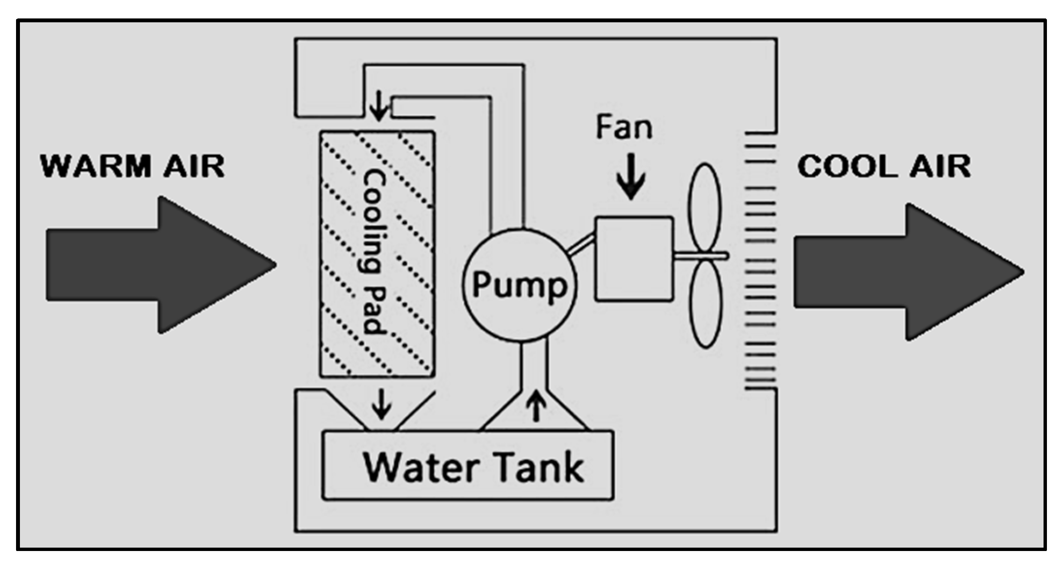
Cooling pads are an integral part of an evaporative cooling system that is equipped with a fan, cooling pad material usually made of metal, cellulose or composite fibers, water distribution manifold, drainage system (drip collector, tray), water circulation system and water pumps. During the system’s operation, water is pumped to the top of the cooling pads and distributed evenly via a specially designed manifold. Water flows through the corrugated surface of the cooling pad and is partly evaporated by the warm air that passes through the pad. The remaining water is drained back to the pumping station through a gutter system. The air that leaves the pad is cooled down (
Figure 1) [
11,
12,
13].
When humid air is evaporatively cooled, its dry bulb temperature is decreased close to its wet-bulb temperature via heat and mass transfer. Evaporative cooling can be initiated either from a humid surface or by spraying water directly into the air to achieve this.
The ideal characteristics and operation in direct evaporative cooling pads are as follows:
fully wetted large contact surfaces to achieve maximum air saturation;
low pressure drop;
media of rigid material;
ease of assembly/disassembly;
ease of maintenance and cleaning.
Other parameters, such as ambient air temperature, relative humidity, water temperature and air velocity (either wind in naturally operating systems or air speed in fan-assisted systems), are all defining factors in enhancing evaporation rate.
Air velocity relates to the average velocity measured at the pad’s inlet or outlet. This is a well-studied parameter with respect to cooling pad performance characterization. High air velocity results in significantly lower saturation effectiveness [
14,
15,
16,
17], temperature drop and relative humidity due to shorter contact time with the pad media. It also leads to higher pressure drop and water consumption, which directly affects electricity consumption. As such, high air velocity is unfavorable in terms of cooling pad performance and should be kept below the recommended values stipulated by the manufacturer’s spec sheets or lab reports [
15,
18,
19].
While greater air velocity inevitably increases the pressure drop through the pad media, Malli et al. [
12] suggest that an increase in the pressure drop results in a substantially lower distribution of the flow field at the pad inlet. Another essential argument is that higher air velocity results in lower saturation effectiveness, which is defined as the “common point” for all direct evaporative cooling pads by Laknizi et al. [
7].
2.2. Physical, Geometrical and Technical Characteristics
The most commonly studied physical parameters of the evaporative cooling pads are as follows:
air velocity (or air mass flow rate);
psychrometric conditions of air mass;
pad thickness;
geometric characteristics and configuration of the pad;
water flow rate.
The pad’s performance can be characterized through the following parameters [
20]:
pad media’s saturation effectiveness;
temperature drop (Δt↓);
pressure drop (Δp↓);
humidity increase achieved in the treated air (ΔRH↑);
water evaporation rate and consumption;
cooling capacity;
coefficient of performance (COP);
heat and mass transfer coefficients.
The most studied geometric parameters in cooling pads are the pad thickness and contact area. Pad thickness corresponds to the length or distance traveled by the airflow. The contact area between water and air mass increases in cooling pads with larger thickness due to longer contact duration (residence time). As such, an increase in the cooling pad thickness enhances saturation effectiveness, temperature drop and water evaporation rate [
21,
22,
23].
Moreover, as the pad thickness increases, so does the independence of the saturation effectiveness from the air velocity [
24]. Furthermore, larger pad thickness also results in higher cooling capacity [
25].
However, it must be taken into consideration that larger pad thickness results in higher pressure drop and, thus, increases operating costs; therefore, the pad thickness must be selected properly to establish a good balance between saturation effectiveness and pressure drop [
26,
27,
28].
Although an increased water flow rate leads to higher saturation effectiveness [
29,
30], according to study results of various types of cooling pad configurations and materials, once the pad media becomes entirely wetted, the saturation effectiveness does not increase further [
31,
32].
Similar observation can be attributed to the heat and mass transfer coefficients [
33]. On the other hand, when the water supply is shut off, the mass transfer coefficient continues to rise until the cooling pad gets insufficiently wetted [
17].
As such, the direct evaporative cooling process, along with using high-performance cooling pads, is known to provide significant energy-saving potential for system operations [
34]. According to a recent study conducted in an office building in Dubai, a direct evaporative cooling pad system presented annual energy savings of 122 MWh with a return on investment of approximately 4 years [
35]. In regions with lower air temperature and higher relative humidity, the payback time may be 3–5 times longer [
36,
37].
However, other significant characteristics, such as the pad material’s endurance and resistance to the external conditions, such as wind, rain, exposure to intense sunlight and thus UV radiation, have triggered the exploration other innovative materials that would meet stringent criteria with regard to material’s resistance to external factors.
3. Methodology
The majority of the existing evaporative cooling systems use relatively expensive cellulosic paper pads. This material is widely used in residential, commercial and agricultural applications as a cooling pad media; however, the fast mineral and dust build-up, as well as the negative impact of weather and UV-light exposure shorten the longevity, durability and service time of such pads. This chapter describes the design of an alternative non-cellulosic evaporative cooling pad constructed from galvanized metal (aluminum) sheets.
Due to constraints of other common materials used in pad technology, the focus of this study, therefore, was the utilization of metal sheet as a cooling pad media and its different cross-sectional shapes. In considering metal sheet handling cost and previous studies, three cross-sectional metal sheet shapes were isolated (W, Z, and Z1) to analyze within the framework of this study with regard to their performance in terms of temperature drop and relative humidity increase between two sides of the duct (before and after).
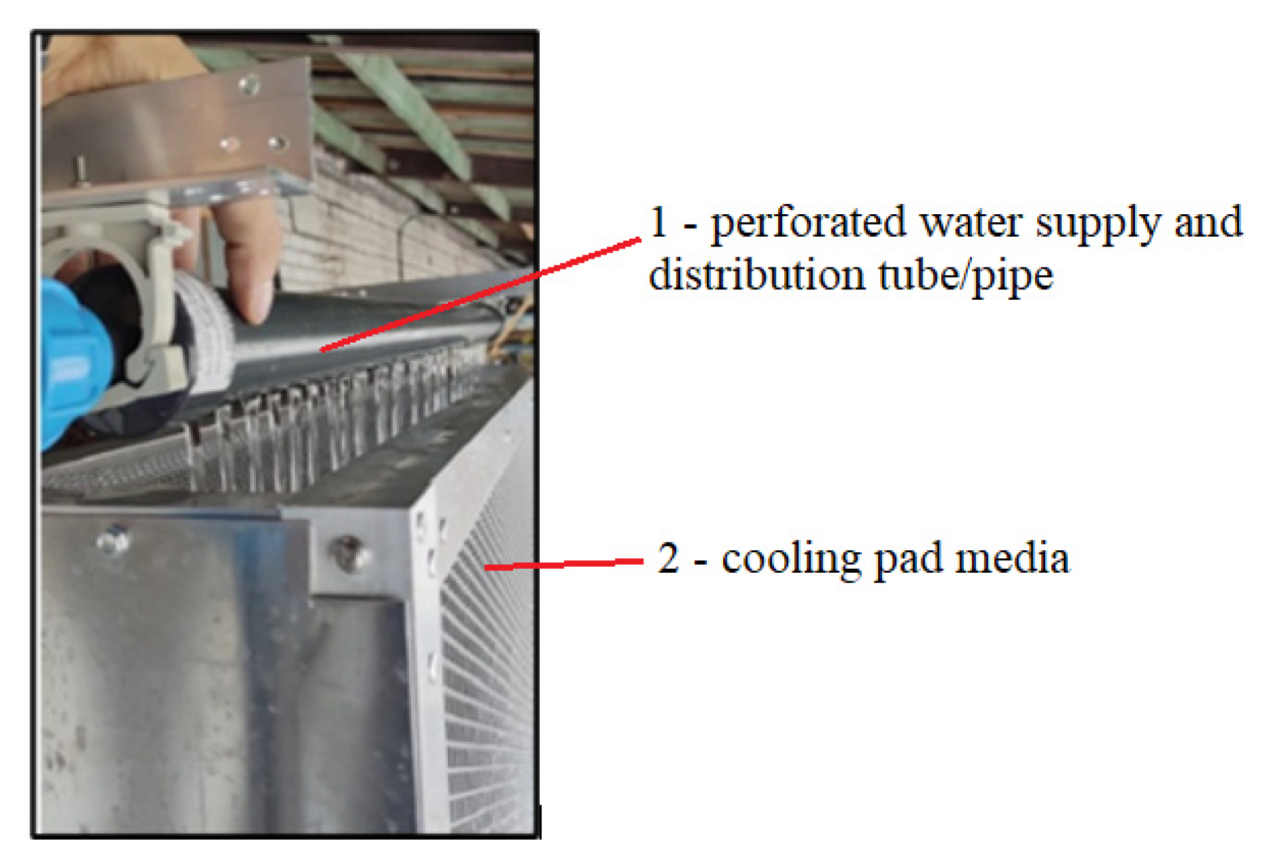
The water distribution and the arrangement in the newly designed cooling pad were executed from the top, as shown in
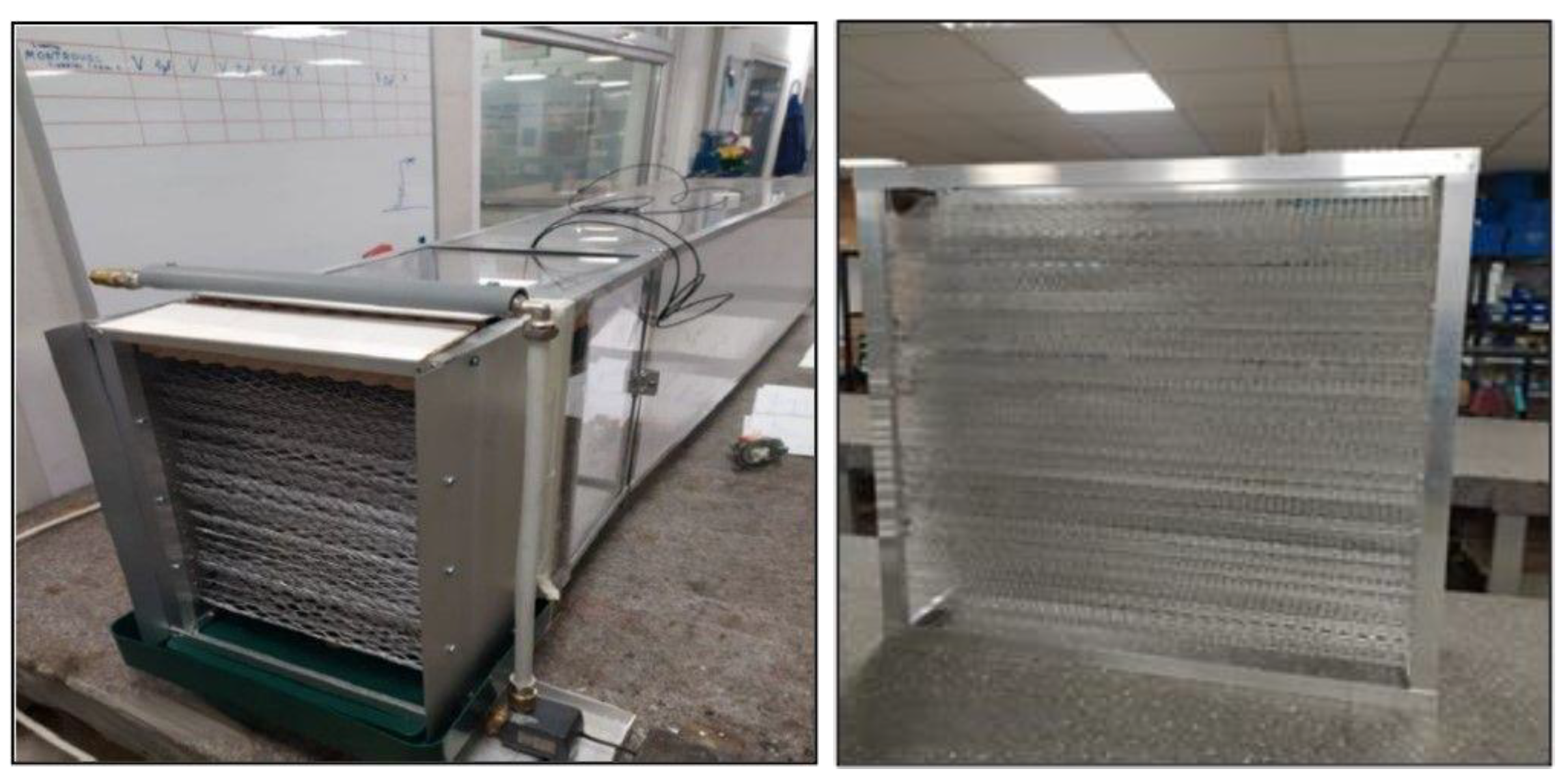
Figure 2. The metal sheets were aligned horizontally in three shapes (W, Z and Z1,
Figure 3), with the gap between the sheets 10–12 mm (the gap varied due to minor assembly imprecision as all parts were put together manually). A water supply system was installed so that water gradually dripped from the top distribution tube on the pad media through small orifices (
Figure 2).
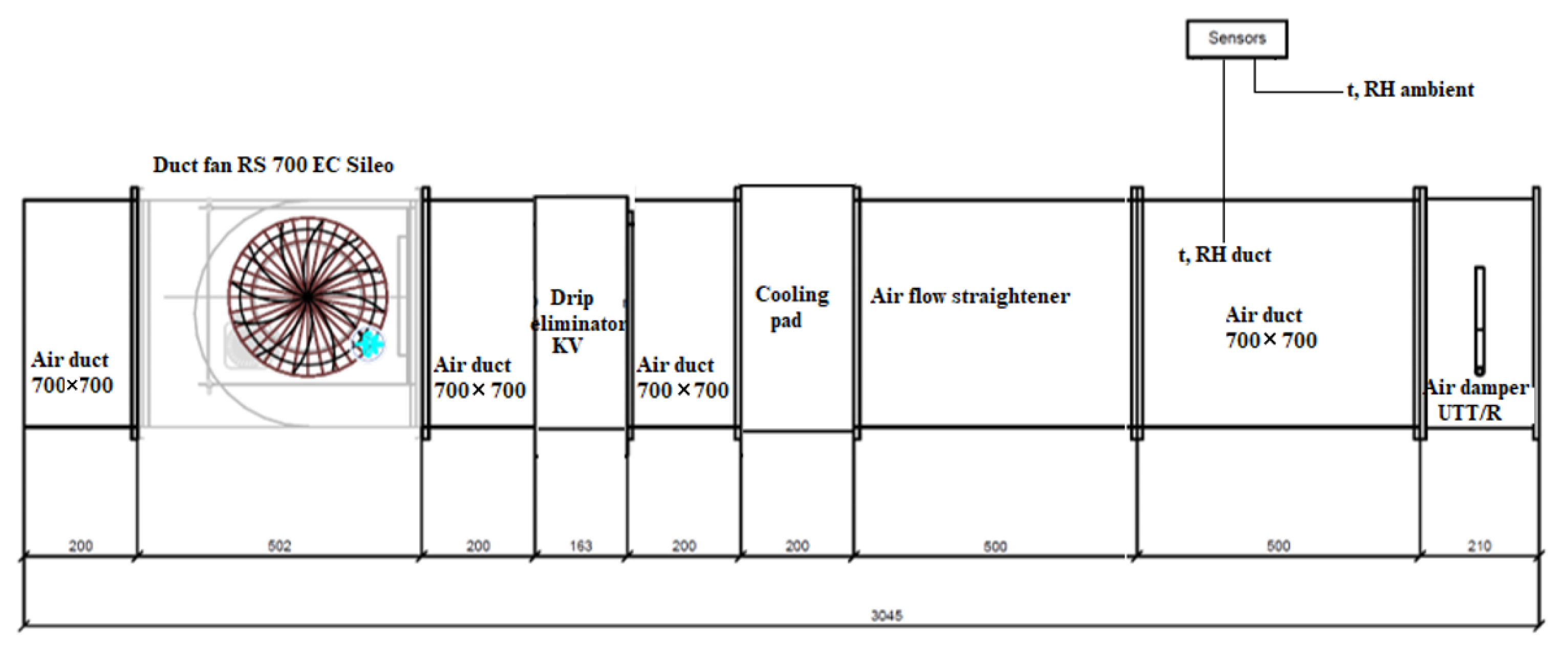
A testing system was set up to investigate various cooling pad patterns made of aluminum mesh (
Figure 4).
The metal sheets of 2 mm in thickness intended as cooling pads of various shapes (W, Z, Z1) were installed in the 3 m long duct tunnel of 700×700 mm in cross-sectional dimensions. Temperature and relative humidity were measured outside the duct (ambient) and inside the duct (
Figure 5).
The cooling pad dimensions were as follows: 700 × 700 × 200 (height × width × depth).
The measurements were conducted over the two following testing sequences:
- (1)
1-h average measurement sequence—(a) ambient temperature, (b) duct temperature, (c) ambient relative humidity and (d) relative humidity inside the duct were measured within the framework of this measurement sequence over 1 h; the average values of the recorded measurements were used for analysis;
- (2)
continuous measurement sequence—the sequence was run at 21 °C and RH < 60% with ambient and duct temperature aligned until the point at which RH inside the duct would reach 80%.
Temperature and relative humidity were measured using HOBO temp/RH sensors with the technical specifications as shown in
Table 1.
4. Results and Discussion
4.1. 1-hr Average Measurement Sequence
The measurements conducted under uncontrolled conditions (non-steady conditions) show that regardless of ambient air temperature, the average temperature drop throughout the measurement sequence is in the ballpark of Δ4.2–5 °C (with slightly higher drop if Z shaped mesh is used and slightly lower drop if Z1 shaped mesh is used).
Indoor relative humidity was kept rather low (~35%) to simulate dry climate conditions. Water was distributed evenly across the cross-sectional frame of each mesh (as shown in
Table 2), and the 1-h average RH measurements indicate a rather similar RH after the mesh. A correlation between generally lower temperature drop (Δt = 4.2 °C) and slightly lower RH increase (ΔRH = 19%) was observed in the case of Z shaped mesh; however, this may not be justified as a strong argument to draw any bold conclusions with regard to the impact of the cross-sectional shape of a cooling pad on its cooling performance.
In all three cases, the observed temperature drop and relative humidity increase were somewhat close; therefore, an additional measurement sequence featuring a continuous measurement cycle was proposed.
4.2. Continuous Measurement Sequence
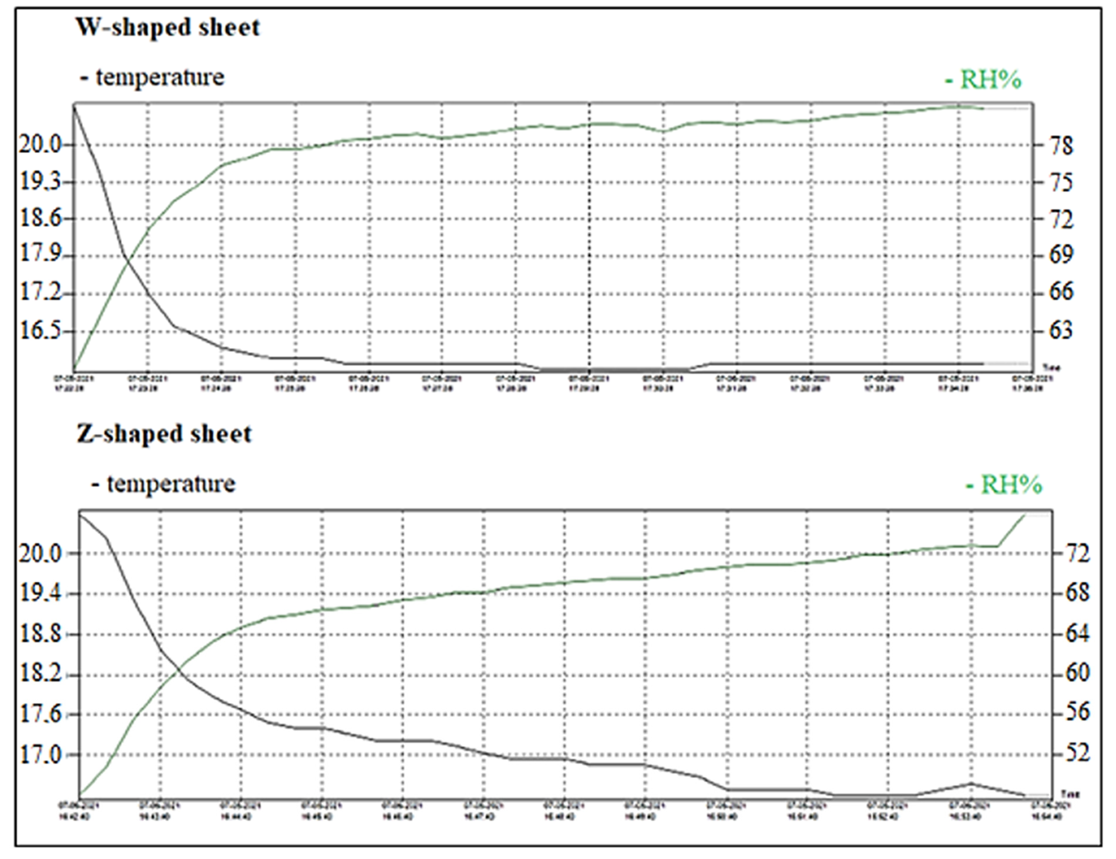
An additional measurement sequence was conducted to compare W-shaped and Z-shaped metal cooling pad cross-sections to presumably present a more accurate and valid dataset on temperature drop at set boundary conditions.
This sequence was carried out at an ambient temperature of 21 °C and relative humidity of <60% with ambient air and duct temperatures aligned. The water was gradually supplied onto the surface of the pad media until the point at which relative humidity inside the duct would reach 80%. The supplied water temperature was 15.7 °C. The time that it took for the RH parameter to reach 80% of saturation inside the duct was recorded, thus, indicating the physical characteristics and saturation rapidity performance of the examined pad shape.
In the case of the W-shaped cross-sectional pattern, it took a little over 14 min, and the temperature drop of 5 °C (16.0 °C at the end of the measurement sequence), while in the case of the Z-shaped cross-sectional pattern, it took around 12 min, and the temperature drop of 4.6 °C (16.4 °C at the end of the measurement sequence), see
Figure 6.
While RH reached the benchmark of 80% slightly faster with a Z-shaped cross-sectional metal sheet, a slightly higher temperature drop was reached with a W-shaped metal sheet.
4.3. Summary
The three examined cross-sectional patterns present slightly similar results with rather insignificant differences in their performance with regard to temperature drop and relative humidity increase. As such, it can be inferred that the three cross-sectional cooling pad patterns reviewed do not possess substantial differences in their performance as long as the cooling pad configuration and boundary conditions remain similar to those employed in the current study.
Another parameter that should be studied more closely on top of the existing measurements is the pressure drop, with dynamic pressure measured before and after the cooling pad. Although within the framework of this study, it was intended to measure the pressure drop differences across the three cross-sectional shapes, preliminary measurements showed very few pressure drop variations ranging below <0.5% across all three shapes. This suggests that the pressure drop variations under the current cooling pad configuration and boundary conditions are negligible. While temperature drop and relative humidity increase are the driving factors for cooling pad performance, the pressure drop is an essential factor when it comes to electricity consumption and, therefore, cannot be neglected.
Further studies should include continuous Δt, ΔRH, Δp measurements to examine various cooling pad metal sheet cross-sectional patterns over a longer timespan (and various background scenarios with regard to predefined initial t and RH) and a wider spectrum of boundary conditions, which would help to develop a consistent t↓ and RH↑ pattern and determine if any of the examined cross-sectional shapes are preferred over another.
Alternatively, while the three proposed cross-sectional shapes have advantages in terms of easier handling (manufacturing, bending/folding process, simpler cleaning, resulting in lower production cost), a wider spectrum of cross-sectional metal sheet shapes might be considered for further studies.
5. Conclusions
In the scope of this study, the research and technical analysis on chillers’ adiabatic pre-cooling solution were performed. The main aim was to identify critical elements for the development of alternative cooling pad characteristics to facilitate heat transfer, lower the air temperature before entering the chiller’s condenser and thus improve the cooling capacity of chiller equipment.
Although larger pad thickness results in increased temperature drop, saturation effectiveness and cooling capacity, which are all contributing factors to the cooling pad’s performance, the pressure drop also increases, which in turn increases fan energy consumption; therefore, the pad thickness must be selected properly to establish a good balance between saturation effectiveness and the pressure drop of a cooling pad.
Due to constraints of other common materials used in pad technology, the focus of this study, therefore, was the utilization of metal sheet as a cooling pad media and its different cross-sectional shapes. In considering metal sheet handling cost and previous studies, three cross-sectional metal sheet shapes were isolated (W, Z, and Z1) to analyze within the framework of this study in terms of their performance in terms of temperature drop and relative humidity increase between two sides of the duct (before and after).
The 1-h average RH measurement sequence indicated a rather similar RH increase after the mesh. A correlation between generally lower temperature drop (Δt↓ = 4.2 °C) and slightly lower RH increase (ΔRH↑ = 19%) was observed in the case of the Z shaped mesh; however, this may not be justified as a strong argument to draw any bold conclusions with regard to the impact of the cross-sectional shape of a cooling pad on its cooling performance.
Therefore, an additional measurement sequence was conducted to compare W-shaped and Z-shaped metal cooling pad cross-sections. The continuous measurement sequence showed that in the case of the W-shaped cross-sectional pattern, it took a little over 14 min, and the temperature drop of 5 °C (16.0 °C at the end of the measurement sequence), while in the case of the Z-shaped cross-sectional pattern, it took around 12 min, and the temperature drop of 4.6 °C (16.4 °C at the end of the measurement sequence) for the relative humidity at the output to reach 80%.
The results of the study suggest that the correlation between Δt↓ and RH↑ is somewhat close in all three cases; however, a slightly higher temperature drop is observed when using a W-shaped metal sheet. However, further studies on the subject focusing on measurement continuity, longevity and boundary conditions’ variability are recommended.
Author Contributions
Conceptualization, A.P. and A.B.; methodology, A.P. and A.M.; resources, A.P.; validation, A.B.; writing—original draft preparation, A.P.; revision, V.J. and D.Z.; visualization, V.J. and A.M.; supervision, A.P.; resources, D.Z. All authors have read and agreed to the published version of the manuscript.
Funding
This research is supported by ERDF project “Development of a new prototype of adiabatic cooling panels to ensure the sustainability and energy efficiency of cooling equipment”, Nr. 1.1.1.1/19/A/002.
Informed Consent Statement
Informed consent was obtained from all subjects involved in the study.
Conflicts of Interest
The authors declare no conflict of interest.
References
- Salata, F.; Falasca, S.; Ciancio, V.; Curci, G.; Grignaffini, S.; de Wilde, P. Estimating building cooling energy demand through the Cooling Degree Hours in a changing climate: A modeling study. Sustain. Cities Soc. 2022, 76, 103518. [Google Scholar] [CrossRef]
- Gi, K.; Sano, F.; Hayashi, A.; Tomoda, T.; Akimoto, K. A global analysis of residential heating and cooling service demand and cost-effective energy consumption under different climate change scenarios up to 2050. Mitig. Adapt. Strateg. Glob. Change 2018, 23, 51–79. [Google Scholar] [CrossRef]
- Zhang, M.; Yang, X.; Cleverly, J.; Huete, A.; Zhang, H.; Yu, Q. Heat wave tracker: A multi-method, multi-source heat wave measurement toolkit based on Google Earth Engine. Environ. Model. Softw. 2022, 147, 105255. [Google Scholar] [CrossRef]
- Shahzad, M.W.; Burhan, M.; Ang, L.; Ng, K.C. Energy-water-environment nexus underpinning future desalination sustainability. Eng. Adv. Desalin. 2017, 413, 52–64. [Google Scholar] [CrossRef]
- Van Vliet, M.T.; Wiberg, D.; Leduc, S.; Riahi, K. Power-generation system vulnerability and adaptation to changes in climate and water resources. Nat. Clim. Change 2016, 6, 375–380. [Google Scholar] [CrossRef]
- Baldwin, J.W.; Dessy, J.B.; Vecchi, G.A.; Oppenheimer, M. Temporally compound heat wave events and global warming: An emerging hazard. Earths Fut. 2019, 7, 411–427. [Google Scholar] [CrossRef] [Green Version]
- De Almeida, G.L.; Pandorfi, H.; Guiselini, C.; Henrique, H.M.; de Almeida, G.A. Use of adiabatic evaporative cooling system in thermal comfort of Girolando cows. Rev. Bras. Eng. Agric. Ambient. 2011, 15, 754–760. [Google Scholar]
- Laknizi, A.; Ben Abdellah, A.; Faqir, M.; Essadiqi, E.; Dhimdi, S. Performance characterization of a direct evaporative cooling pad based on pottery material. Int. J. Sustain. Eng. 2021, 14, 46–56. [Google Scholar] [CrossRef]
- Ahmed, E.M.; Abaas, O.; Ahmed, M.; Ismail, M.R. Performance evaluation of three different types of local evaporative cooling pads in greenhouses in Sudan. Saudi J. Biol. Sci. 2011, 18, 45–51. [Google Scholar] [CrossRef] [Green Version]
- Borodinecs, A.; Zajecs, D.; Lebedeva, K.; Bogdanovics, R. Mobile off-grid energy generation unit for temporary energy supply. Appl. Sci. 2022, 12, 673. [Google Scholar] [CrossRef]
- Millers, R.; Korjakins, A.; Lešinskis, A.; Borodinecs, A. Cooling panel with integrated PCM layer: A verified simulation study. Energies 2022, 13, 5715. [Google Scholar] [CrossRef]
- Jain, J.K.; Hindoliya, D.A. Experimental performance of new evaporative cooling pad materials. Sustain. Cities Soc. 2011, 1, 252–256. [Google Scholar] [CrossRef]
- Malli, A.; Seyf, H.R.; Layeghi, M.; Sharifian, S.; Behravesh, H. Investigating the performance of cellulosic evaporative cooling pads. Energy Convers. Manag. 2011, 52, 2598–2603. [Google Scholar] [CrossRef]
- Laknizi, A.; Mahdaoui, M.; Abdellah, A.B.; Anoune, K.; Bakhouya, M.; Ezbakhe, H. Performance analysis and optimal parameters of a direct evaporative pad cooling system under the climate conditions of Morocco. Case Stud. Therm. Eng. 2019, 13, 100362. [Google Scholar] [CrossRef]
- Ndukwu, M.; Manuwa, S. A techno-economic assessment for viability of some waste as cooling pads in evaporative cooling system. Int. J. Agric. Biol. Eng. 2015, 8, 151–158. [Google Scholar]
- Doğramacı, P.A.; Riffat, S.; Gan, G.; Aydın, D. Experimental study of the potential of eucalyptus fibres for evaporative cooling. Renew. Energy 2019, 131, 250–260. [Google Scholar] [CrossRef]
- Liao, C.M.; Singh, S.; Wang, T.S. Characterizing the performance of alternative evaporative cooling pad media in thermal environmental control applications. J. Environ. Sci. Health Part A Toxic Hazard. Subst. Environ. Eng. 1998, 33, 1391–1417. [Google Scholar] [CrossRef]
- Rong, L.; Pedersen, P.; Jensen, T.L.; Morsing, S.; Zhang, G. Dynamic performance of an evaporative cooling pad investigated in a wind tunnel for application in hot and arid climate. Biosyst. Eng. 2017, 156, 173–182. [Google Scholar] [CrossRef]
- Sellami, K.; Feddaoui, M.; Labsi, N.; Najim, M.; Oubella, M.; Benkahla, Y.K. Direct evaporative cooling performance of ambient air using a ceramic wet porous layer. Chem. Eng. Res. Des. 2019, 142, 225–236. [Google Scholar] [CrossRef]
- Nada, S.A.; Elattar, H.F.; Mahmoud, M.A.; Fouda, A. Performance enhancement and heat and mass transfer characteristics of direct evaporative building free cooling using corrugated cellulose papers. Energy 2020, 2011, 118678. [Google Scholar] [CrossRef]
- Tejero-González, A.; Franco-Salas, A. Optimal operation of evaporative cooling pads: A review. Renew. Sustain. Energy Rev. 2021, 151, 111632. [Google Scholar] [CrossRef]
- Franco, A.; Valera, D.L.; Peña, A. Energy efficiency in greenhouse evaporative cooling techniques: Cooling boxes versus cellulose pads. Energies 2014, 7, 1427–1447. [Google Scholar] [CrossRef]
- Barzegar, M.; Layeghi, M.; Ebrahimi, G.; Hamzeh, Y.; Khorasani, M. Experimental evaluation of the performances of cellulosic pads made out of Kraft and NSSC corrugated papers as evaporative media. Energy Convers. Manag. 2012, 54, 24–29. [Google Scholar] [CrossRef]
- Sellami, K.; Labsi, N.; Najim, M.; Benkahla, Y.K. Numerical Simulations of Heat and Mass Transfer Process of a Direct Evaporative Cooler from a Porous Layer. J. Heat Trans. 2019, 141, 071501. [Google Scholar] [CrossRef]
- Beshkani, A.; Hosseini, R.E.Z.A. Numerical modeling of rigid media evaporative cooler. Appl. Therm. Eng. 2006, 26, 636–643. [Google Scholar] [CrossRef]
- Gunhan, T.U.N.C.A.Y.; Demir, V.E.D.A.T.; Yagcioglu, A.K. Evaluation of the Suitability of Some Local Materials as Cooling Pads. Biosyst. Eng. 2007, 96, 369–377. [Google Scholar] [CrossRef]
- Alam, M.F.; Sazidy, A.S.; Kabir, A.; Mridha, G.; Litu, N.A.; Rahman, M.A. An experimental study on the design, performance and suitability of evaporative cooling system using different indigenous materials. AIP Conf. Proc. 2017, 1851, 020075. [Google Scholar] [CrossRef]
- Martinez, P.; Ruiz, J.; Martínez, P.J.; Kaiser, A.S.; Lucas, M.J.A.T.E. Experimental study of the energy and exergy performance of a plastic mesh evaporative pad used in air conditioning applications. Appl. Therm. Eng. 2018, 138, 675–685. [Google Scholar] [CrossRef]
- He, S.; Gurgenci, H.; Guan, Z.; Huang, X.; Lucas, M. A review of wetted media with potential application in the pre-cooling of natural draft dry cooling towers. Renew. Sustain. Energy Rev. 2015, 44, 407–422. [Google Scholar] [CrossRef]
- Fouda, A.; Melikyan, Z.J.A.T.E. A simplified model for analysis of heat and mass transfer in a direct evaporative cooler. Appl. Therm. Eng. 2011, 31, 932–936. [Google Scholar] [CrossRef]
- Nada, S.A.; Fouda, A.; Mahmoud, M.A.; Elattar, H.F. Experimental investigation of energy and exergy performance of a direct evaporative cooler using a new pad type. Energy Build. 2019, 203, 109449. [Google Scholar] [CrossRef]
- Yan, M.; He, S.; Li, N.; Huang, X.; Gao, M.; Xu, M.; Miao, J.; Lu, Y.; Hooman, K.; Che, J.; et al. Experimental investigation on a novel arrangement of wet medium for evaporative cooling of air. Int. J. Refrig. 2021, 124, 64–74. [Google Scholar] [CrossRef]
- He, S.; Guan, Z.; Gurgenci, H.; Jahn, I.; Lu, Y.; Alkhedhair, A.M. Influence of ambient conditions and water flow on the performance of pre-cooled natural draft dry cooling towers. Appl. Therm. Eng. 2014, 66, 621–631. [Google Scholar] [CrossRef] [Green Version]
- Franco, A.; Valera, D.L.; Madueno, A.; Peña, A. Influence of water and air flow on the performance of cellulose evaporative cooling pads used in mediterranean greenhouses. Trans. ASABE 2010, 53, 565–576. [Google Scholar] [CrossRef]
- Olosunde, W.A.; Igbeka, J.C.; Olurin, T.O. Performance evaluation of absorbent materials in evaporative cooling system for the storage of fruits and vegetables. Int. J. Food Eng. 2009, 5, 1. [Google Scholar] [CrossRef]
- Borodinecs, A.; Lebedeva, K.; Prozuments, A.; Brahmanis, A.; Grekis, A.; Zajecs, D.; Zekunde, A.; Vatin, N. Feasibility of Reducing Electricity Consumption of Air Conditioning Equipment by Condenser Direct Evaporative Cooling Technology. Example of Case Study in Dubai. Atmosphere 2021, 12, 1205. [Google Scholar] [CrossRef]
- Shipkovs, P.; Kashkarova, G.; Lebedeva, K.; Shipkovs, J. Perspectives for solar thermal energy in the Baltic states. In Proceedings of the Solar World Congress 2005: Bringing Water to the World, Orlando, FL, USA, 6–12 August 2005. [Google Scholar]
| Publisher’s Note: MDPI stays neutral with regard to jurisdictional claims in published maps and institutional affiliations. |
© 2022 by the authors. Licensee MDPI, Basel, Switzerland. This article is an open access article distributed under the terms and conditions of the Creative Commons Attribution (CC BY) license (https://creativecommons.org/licenses/by/4.0/).
