Abstract
Heat recovery systems based on thermoelectric micro-generators (µ-TEGs) can play a significant role in the development of wireless, energetically autonomous electronics. However, to date, the power density recovered for low temperature differences using µ-TEGs is limited to a few micro-watts or less, which is still insufficient to power a wide-range of wireless devices. To develop more efficient µ-TEGs, material, device and system requirements must be considered simultaneously. In this study, an innovative design of an in-plane µ-TEG integrating bismuth telluride forming sinusoidal-shaped trenches is reported. Using 3D numerical modelling, the influence of boundary conditions, parasitic effects (electrical and thermal contact resistances), and transport properties of thermoelectric materials on the output power of these µ-TEGs are investigated in detail for a small temperature difference of 5 K between the hot and cold sources. Compared to wavy-shaped trenches, this novel shape enables enhancing the output power. The results show that either the thermal conductivity or the Seebeck coefficient of the active n- and p-type semiconductors is the key parameter that should be minimized or maximized, depending on the magnitude of the parasitic effects.
1. Introduction
Thermoelectric micro-generators (µ-TEGs) are able to convert directly heat into electricity thanks to the Seebeck effect. These devices hold great promise for harvesting a fraction of the huge amount of waste heat (estimated to represent 60% of the total energy produced) released into our environment to power numerous systems, including batteries, sensors, or connected objects (IoT), thereby contributing to the development of wireless, energetically autonomous electronics driven by the deployment of the 5G network.
Several µ-TEG architectures have been proposed in the last decades with organic or inorganic materials as the active TE materials [,,,,,,,,,,,,,,,,,,,,,,,,,,,,,]. They can be divided into two categories [,,]: the in-plane configuration where the heat flux flows parallel to the substrate, and the cross-plane configuration where the heat flux is perpendicular to the substrate. Each of these configurations has its own advantages and drawbacks. For instance, the in-plane configuration offers the possibility to generate a high output voltage even for low temperature differences between the hot and cold sources while maintaining a small level of thermo-mechanical stress. On the other hand, the cross-plane architecture presents the advantage to have a small internal resistance, which is desirable for achieving a high output power, but is more sensitive to thermo-mechanical issues and electrical contact resistances [,].
Recently, we developed an innovative µ-TEG design that combines most of the positive attributes of these two architectures. [] The basic unit of this harvester, designed to operate near room temperature, is shown in Figure 1. It consists of an in-plane structure built from co-laminated copper-polyamide-copper thin plates. The top copper part is etched up to the polyamide sheet to create a wavy-shaped channel filled by n- and p-type bismuth telluride materials deposited by a PVD process. The lower copper part is also etched along the x direction to create a channel that enables to decouple the bottom copper layers both electrically and thermally. The top and bottom copper parts are connected electrically and thermally by small metallic Cu rivets. In our previous work, this design has been shown to exhibit several advantages: (i) a low internal electrical resistance thanks to a high surface and thick thickness of the TE elements, (ii) the possibility to vary the geometry, (iii) the use of Cu that can play the role of heat spreaders and can be easily soldered to the heat sources and heat sink, and (iv) a simple fabrication process allowing for the production of modules integrating a large number of this basic thermocouple unit. As a proof of principle, we demonstrated, through an approach combining numerical modelling and experiments, that such a structure is able to produce an electrical power of several µW per thermocouple under small temperature differences around room temperature (typically few K), ranking these µ-TEGs among the best in-plane TE devices currently available.

Figure 1.
(a) Design of the µ-TEG integrating n- and p-type Bi2Te3-based materials; (b) typical dimensions of the µ-TEG are indicated.
Here, in an effort to further improve the different fabrication steps and the durability of this promising structure, a novel geometry of the TE trench is proposed (Figure 2). From a numerical modelling, we show that the sinusoidal shape offers an improved electrical output power for the two most common boundary conditions used in the literature: fixed temperature and mixed boundary conditions. Interestingly, our numerical results evidence that either the thermal conductivity or the Seebeck coefficient of the TE materials is the key parameter that should be minimized or maximized, depending on the magnitude of the parasitic effects represented by a non-ideal thermal coupling at the cold source and a non-zero electrical contact resistance.

Figure 2.
New design of the µ-TEG with a sinusoidal trench.
The paper is organized as follows. After briefly introducing the numerical modelling, the third part will focus on the electrical power that can be generated by the novel design under fixed temperature conditions for various magnitudes of the electrical contact resistance. Then, the influence of parasitic effects on the maximum output power () under mixed boundary conditions are presented and discussed. The impact of the dimensionless thermoelectric figure of merit (ZT) of the active materials on will be also discussed in detail.
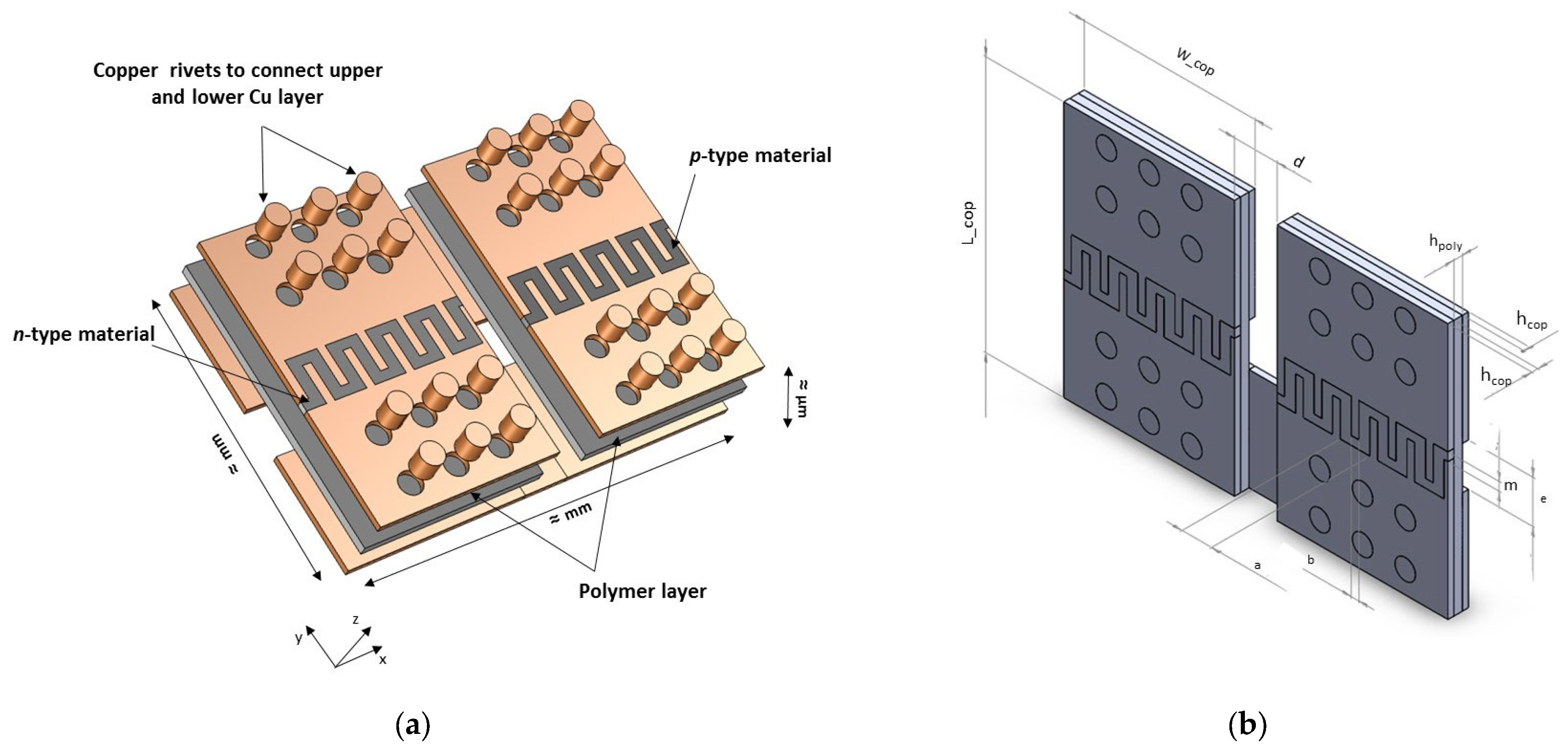
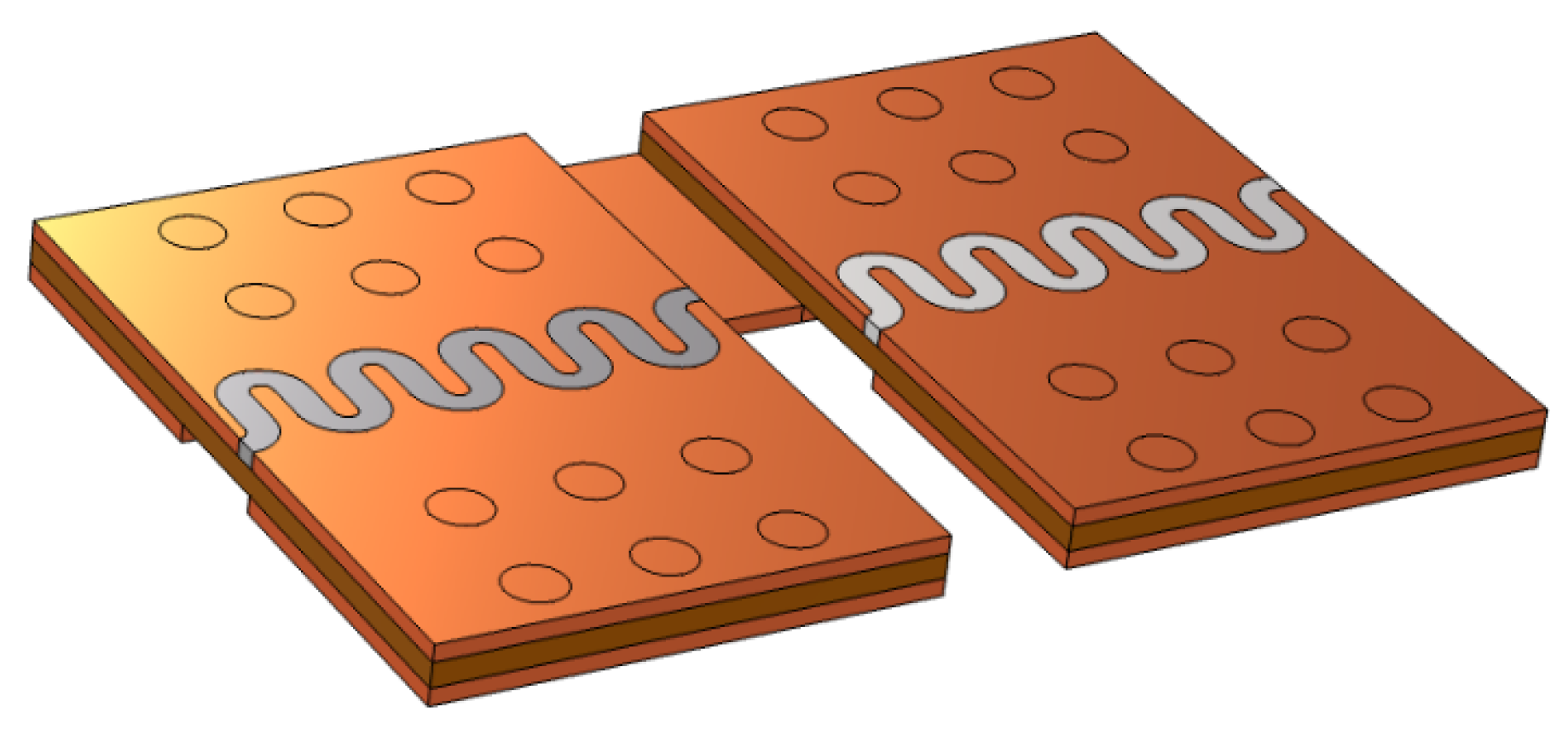
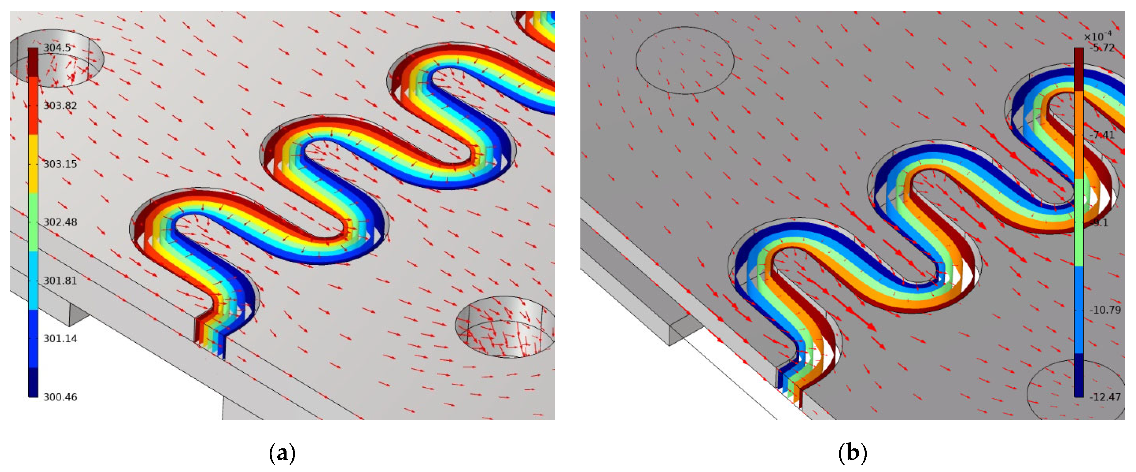
2. Numerical Modelling
The thermoelectric effects result from the coupling of the heat and charge transport inside a conductor. From thermodynamics of irreversible phenomena, it can be shown that, under stationary state conditions and for an isotropic material, the heat ( and current () flux satisfy the following equations:
where is the Peltier coefficient, κ is the total thermal conductivity, is the absolute temperature, σ is the electrical conductivity, is the electric field that derives from the potential V (), and α is the Seebeck coefficient. All the transport coefficients defined previously are supposed to be scalars.
Equations (1)–(4) can be solved numerically by finite-element analyses using Comsol Multiphysics to determine the temperature and electrical potential fields. Herein, the basic unit of the µ-TEG was built and the meshing was optimized to reduce the calculation time without sacrificing the accuracy of the results. A load resistance () was connected electrically in series to the µ-TEG in order to derive the output electrical power delivered at the load resistance from (where I is the electrical current flowing in the circuit). The thermal and electrical boundary conditions are presented in the Supplementary Material.
Overall, two types of boundary conditions were considered in this study. The first one, considered as ideal, supposes that the µ-TEG is perfectly connected to hot and cold thermostats with fixed temperatures TH = 305 K and TC = 300 K, respectively. In the second case, one end of the thermocouple is connected to a hot thermostat (TH = 305 K), while a convective heat transfer is assumed between the cold side of the thermocouple and the surrounding environment supposed to remain at 300 K. This second regime is the so-called mixed boundary conditions, which are closer to those encountered in real applications. This general approach allows for the study of the influence of several key parameters, including the physical properties of the materials, the geometrical parameters of the µ-TEG, the load resistance, and the electrical and thermal contact resistances, on the electrical power delivered at the load resistance.
The physical properties of the materials (Bi2Te3-based materials, polyamide, and copper) used in these calculations are listed in Table 1. Considering the small temperature difference applied between the hot and cold thermostat (TH − TC = = 5 K), the physical properties were assumed constant.

Table 1.
Physical properties of the materials considered in the numerical simulations.
The geometrical parameters of the µ-TEG are listed in Table 2 and correspond to the optimized parameters determined in our previous study []. The electrical contact resistance between the semiconductor and copper varied between 0 (perfect electrical contact) and 10−4 Ω cm2. This upper limit is representative of a poor electrical contact. The values of the heat exchange coefficient, , examined in this study cover the range from 5 W m−2 K−1, corresponding to natural air convection, up to 1000 W m−2 K−1 that corresponds to forced water convection.

Table 2.
Numerical values of the geometrical parameters used in the modelling.
3. Results and Discussion
3.1. Fixed Temperature Boundary Conditions
The temperature and electrical potential fields, computed under close circuit conditions for a load resistance matching that of the internal resistance of the µ-TEG, are presented in Figure 3a. The shape of both isotherm and equipotential curves follows the sinusoidal shape of the TE elements. The temperature difference undergone by the TE elements () is close to the temperature difference between the hot and cold thermostats (5 K), thanks to the high thermal conductivity of copper. As a consequence, the electrical field (heat flux) is perpendicular to the isotherm (equipotential), as illustrated in Figure 3b.

Figure 3.
(a) Temperature and heat flux and (b) voltage and electrical field in the TE element.
This good coupling allows to reach appreciable electrical power values, as shown in Figure 4, where the dependence of the output power on is presented for various values of .

Figure 4.
Output power as a function of the load resistance, , for various electrical contact resistances .
Regardless of the value of , is reached when the load resistance is equal to the internal resistance R of the thermocouple. This matching condition ( 1) is expected when fixed boundary conditions are assumed []. One important aspect of these results is that exceeds by 7% that obtained with our previous design []. The reason behind this improvement is due to two factors: an increase in the surface of the TE elements, resulting in a lowering of the internal resistance R, and a higher . A second beneficial impact of the sinusoidal shape of the trench is the higher quality of the interfaces achieved between the TE semiconductors and copper during the PVD deposition. Figure 4 also underlines the detrimental impact of high electrical contact resistance on . When exceeds 10−5 Ω cm2, dramatically decreases to a level that could limit the use of such device.
3.2. Mixed Temperature Boundary Conditions
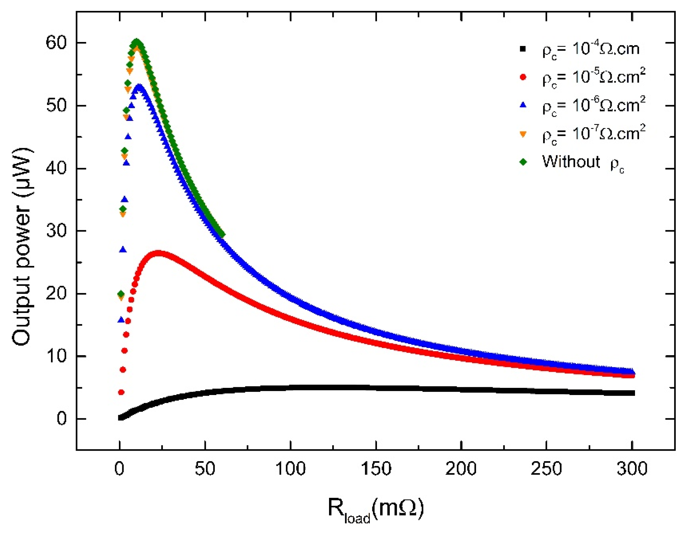
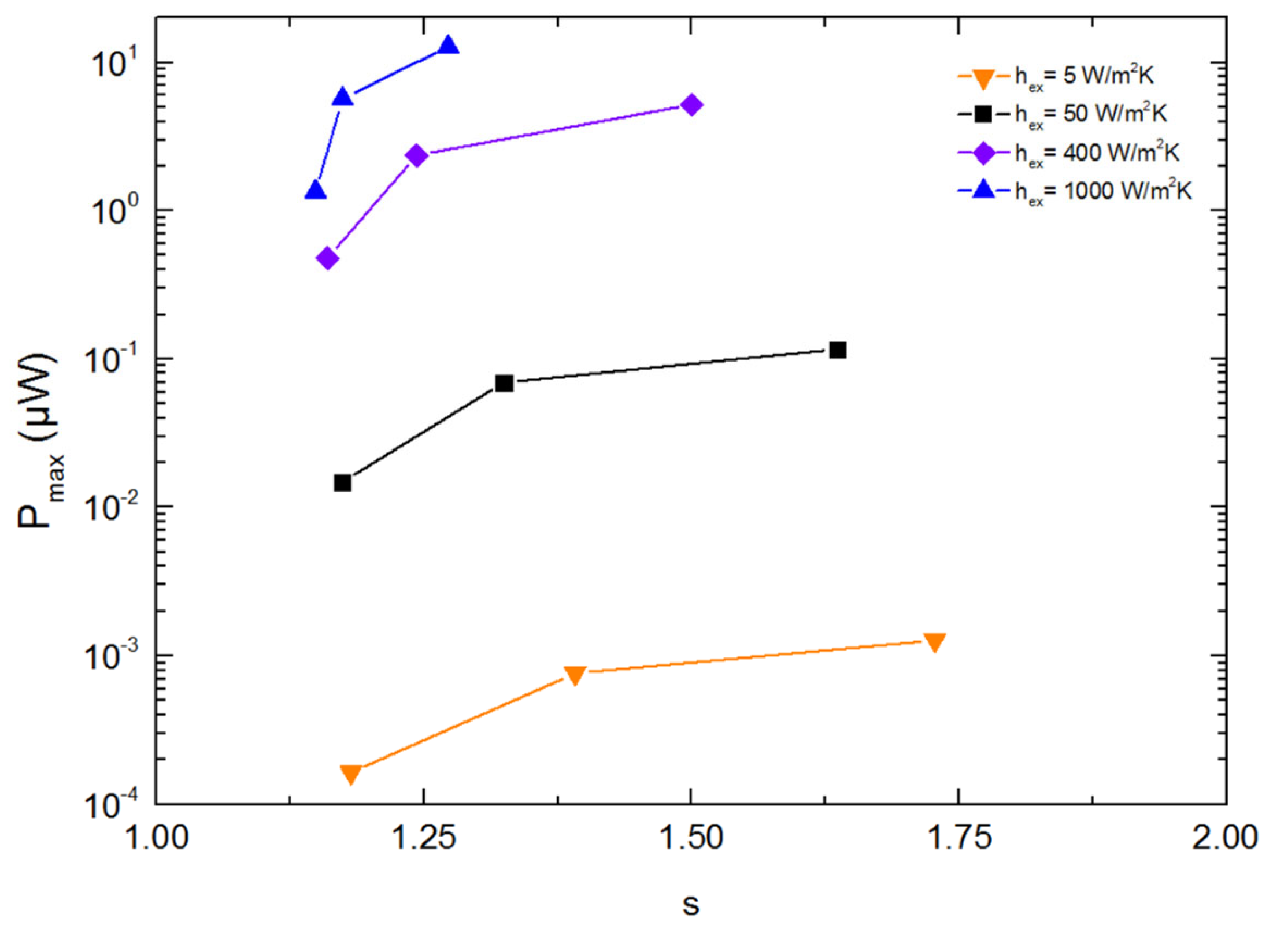
3.2.1. Influence of Parasitic Effects
In most near-room-temperature applications, the contact between the µ-TEG and the cold thermostat is far from ideal. Under these more realistic conditions, the µ-TEG operates under heat flux conditions. In this case, the non-perfect coupling to the cold thermostat should be considered as a parasitic effect, since it degrades the temperature difference undergone by the TE elements and thus the overall performance of the µ-TEG, as shown in Figure 5, where is represented as a function of for 5 K. With an efficient cooling ( W m−2 K−1), the degradation of is moderate, still leading to an appreciable value of when is not too high. However, when the cooling is ensured by air ( 5 W m−2 K−1), amounts only to a few mK for 10−4 cm2 and 10−6 cm2 that is less than 0.6% and 0.4% of the applied temperature difference between the hot and cold thermostat. These values, which are extremely low, strongly limit that drops from 5 µW in the ideal case (fixed temperature boundary conditions) to only 10−3–10−4 µW. As already discussed elsewhere [,], the TE materials operate in a regime limited by the thermal sink, which is reached when the thermal resistance of the heat sink is much larger than the thermal resistance of the TE element. A direct consequence of this regime is that, for a fixed , the maximum temperature that can be expected on the TE materials, when is null, is for an optimized thickness of the TE elements [].

Figure 5.
Maximal output power as a function of for different values of the heat exchange coefficient.
Due to the versatility of the design of this µ-TEG, this problem can be partially mitigated by simply increasing the surface of the cold side of the µ-TEG to favor dissipation. A reasonable upper limit for this surface is approximately 80Sc, which would correspond to an equivalent heat transfer coefficient of 400 W m−2 K−1 for alone. Under this condition, 2.52 K regardless of the value of , leading to a maximum output power ranging from 0.48 to 5.9 µW for 10−4 cm2 and 10−6 cm2, respectively. These values are 6.7% higher than those achieved with our previous design, and are among the best values reported in the literature [].
In the heat flux regime at the cold side, the impedance matching condition found with fixed temperature boundary conditions ( = 1) is no longer satisfied. As shown in Figure 6, where the dependence of on s is represented, the numerical modeling shows that > 1 at . The reason for this deviation is linked to the fact that is a function of and in this regime. Thus, the maximization of the electrical power with respect to introduces a correction term to the matching impedance condition, the sign of which depends on the first derivative . Since increasing (or ) decreases the current in the circuit and hence, the Joule and Peltier heats at the cold side of the µ-TEG, becomes larger and > 1.

Figure 6.
Maximum output power as a function of s with varying magnitude of electrical contact resistance.
Depending on the electrical and thermal properties of the n- and p-type thermoelectric materials, the electrical contact resistance and the capacity to extract the heat at the cold side (through ), can deviate from unity. To illustrate this point, Figure 6 shows the variation in as a function of for different values of . Values close to 2 can be obtained when both and decrease. To alleviate the heat production at the cold side and favor a higher , it is advantageous to decrease the current or increase the value of the load resistance.
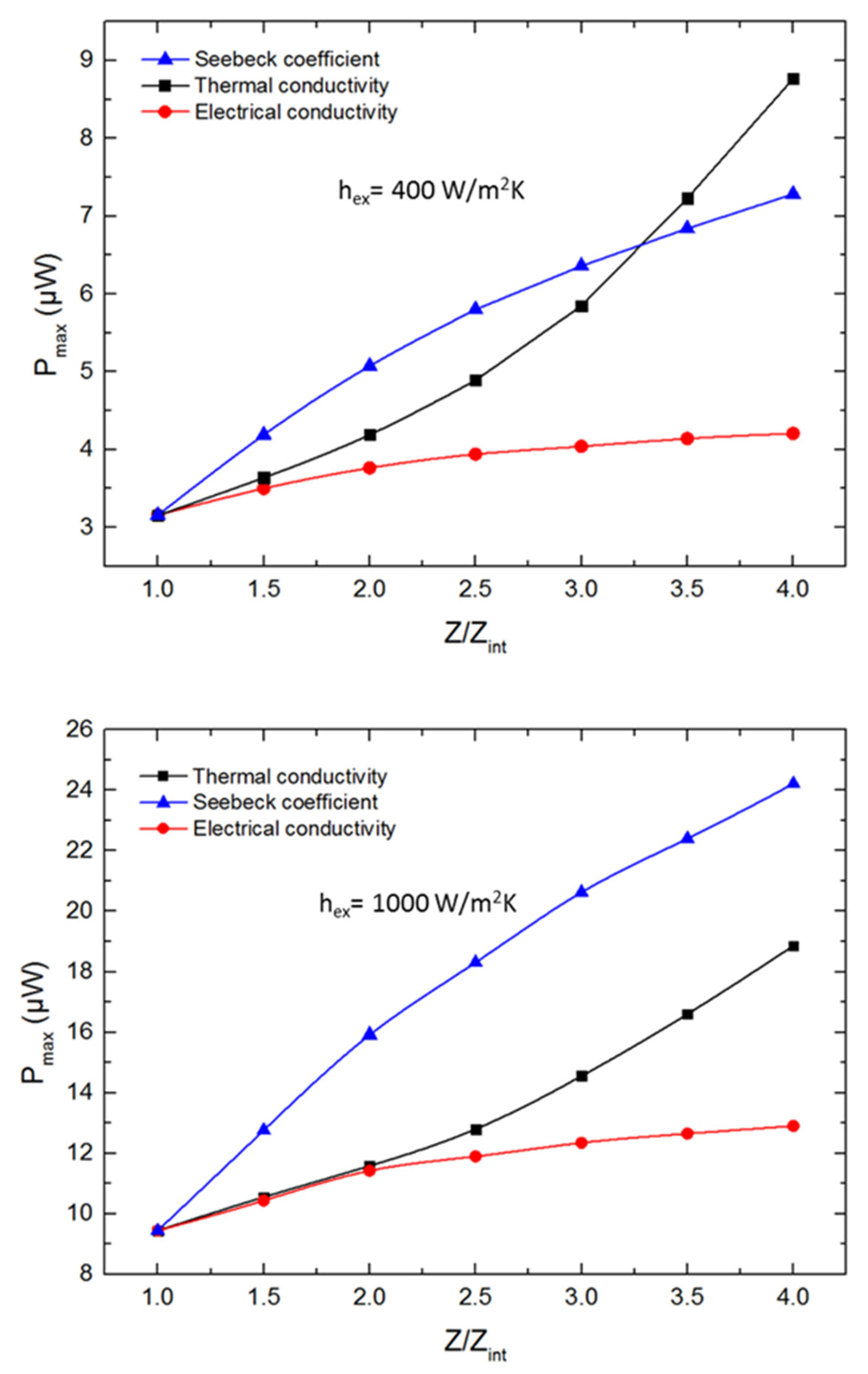
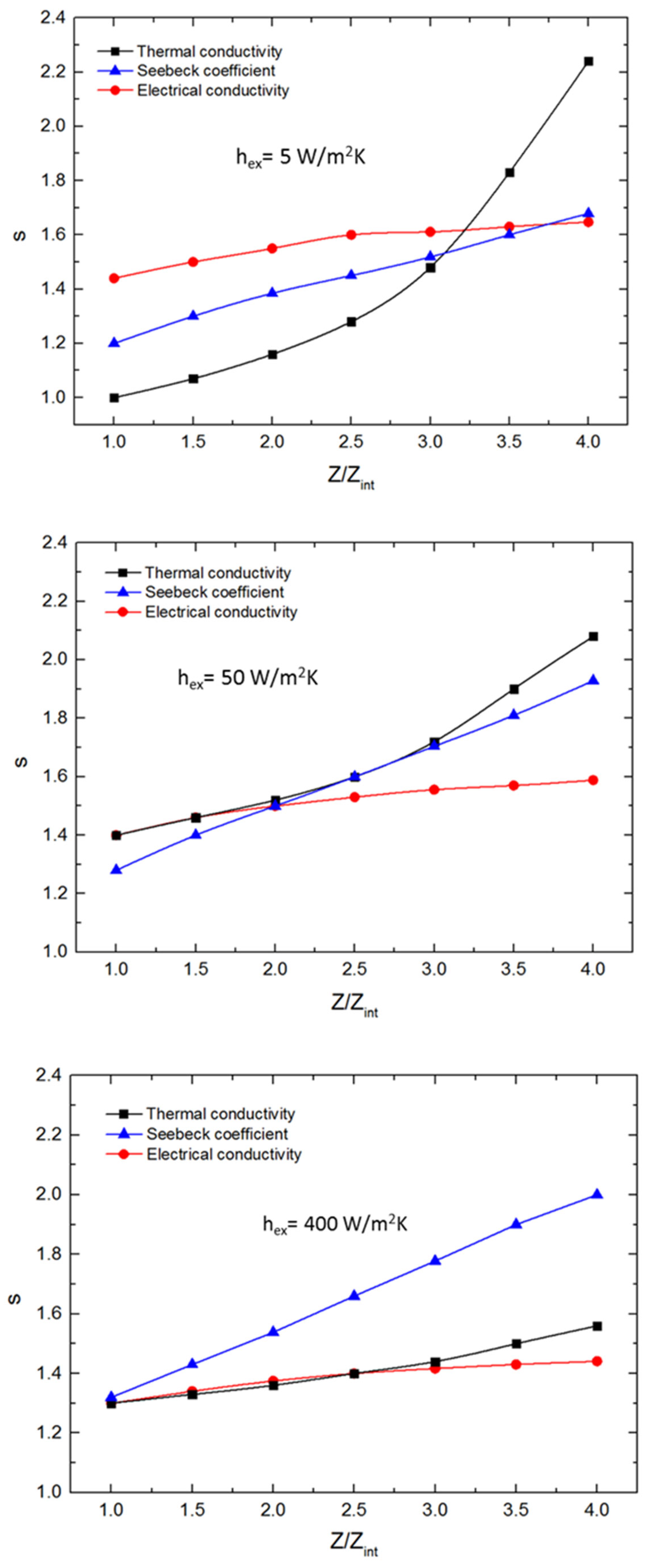
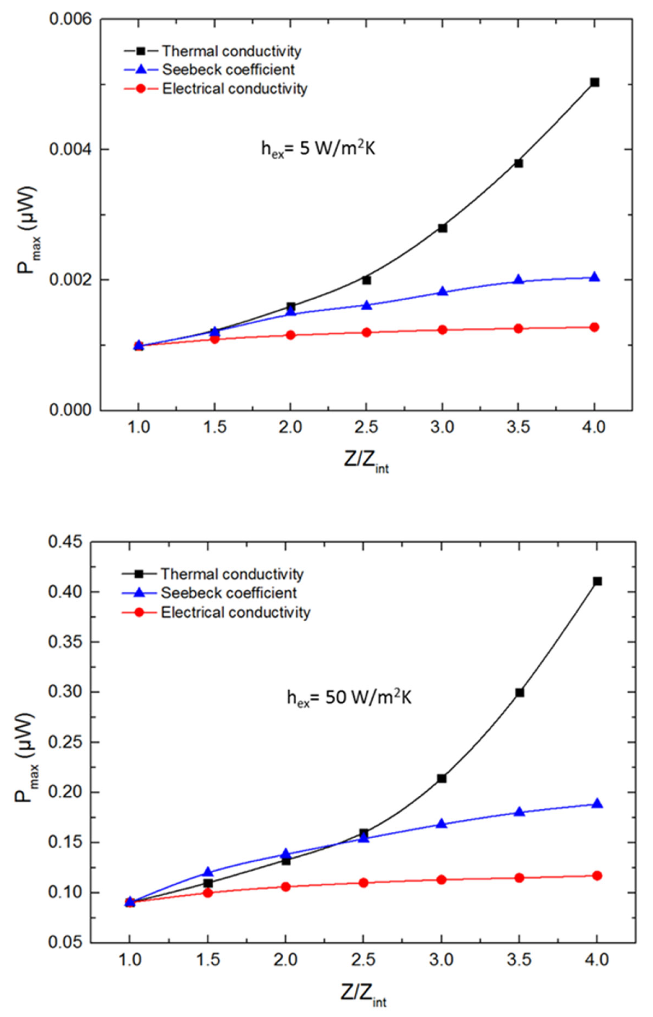
3.2.2. Influence of Thermoelectric Properties
So far, the transport properties of the thermoelectric materials have been considered to be constants. However, it is also interesting to derive guiding principles to further improve the performance of these promising µ-TEGs. For an ideal coupling with the hot and cold sources, it is well known that the dimensionless thermoelectric figure of merit (thermal conductivity , Seebeck coefficient , and electrical resistivity ), is the key parameter to optimize in order to achieve the highest efficiency, while the power factor is the prime parameter that should be maximized to achieve the highest electrical output power. When non-ideal conditions are applied on the µ-TEG, the results discussed above have shown that the latter criteria are no longer valid, since the thermal resistance of the device should be as low as possible to achieve the highest . To satisfy this requirement, thermoelectric materials with a low thermal conductivity should be chosen. Combining this criterion with a high power factor makes the use of the metric pertinent in this case.
For this reason, the impact of on the maximum electrical power has been investigated under mixed boundary conditions. To probe the sensitivity of each transport properties, only one physical property at a time was varied to obtain a fourfold improvement in the value. The initial value was evaluated according to the transport properties of the p-type compound (see Table 1) and assuming that the transport properties of the n- and p-type materials are similar to simplify the study.
The maximum electrical power as a function of the ratio for different values of is shown in Figure 7 for 10−5 cm2 (whatever the choice of the following conclusions will be the same). When ≤ 50 W m−2 K−1, an improvement in is beneficial to improve , even though the improvement is not strictly similar. When 2, it is more interesting to focus on lowering the thermal conductivity or increasing the Seebeck coefficient, while for 2, lowering the thermal conductivity is the best strategy.


Figure 7.
Maximum output power as a function of for different values of . All of these calculations were performed with 10−5 cm2.
The prominent role of to achieve a high can be understood qualitatively. When λ decreases, the of the semiconductors increases, but so does the amount of heat to be extracted at the cold side, leading to a higher . Increasing or decreasing also increases , but produces more thermal power at the cold side, negatively offsetting the benefit of increasing . These conclusions no longer hold when > 50 W m−2 K−1, that is, when the cooling becomes efficient, for which a gain is observed when increases. Only an incremental improvement of is obtained when drops due to the contribution of the electrical contact resistance that remains constant. The benefit of a reduced thermal conductivity becomes apparent only when the ratio is higher than 3.5 for 400 W m−2 K−1, and even higher for 1000 W m−2 K−1. For the sake of completeness, the value of associated with each of the previous situation is indicated in Figure 8. Strong deviations from unity are observed for high Seebeck coefficient values when W m−2 K−1. To compensate the high Peltier heat, consecutive to high Seebeck values, created at the cold side of the thermoelectric material, it is beneficial to reduce the current by making the load resistance higher than for the ideal case. These results are in agreement with a previous report [].


Figure 8.
s ratio as a function of for different values of .
4. Conclusions
In summary, a novel design of our previously reported µ-TEG, which consists of a modification of the shape of the trench in which the TE materials are deposited, has been presented. By considering the two most common boundary conditions, our numerical modelling demonstrates that the transformation of the wavy shape into a sinusoidal shape results in an improved performance for a small temperature difference of 5 K around room temperature. Our results further highlight that the pertinent transport property of the TE materials that should be optimized directly depends on the magnitude of the parasitic effects that negatively affect the thermoelectric performance of the device. These last results provide guidance for the optimization of TE materials that may be integrated into future µ-TEGs undergoing varying boundary conditions at the cold side.
Supplementary Materials
The following supporting information can be downloaded at: https://www.mdpi.com/article/10.3390/en15103746/s1, Figure S1: Sketches of the µ-TEG showing the electrical and thermal boundary conditions.
Author Contributions
Conceptualization, S.E.O., B.L., C.C., F.K., G.S., E.M., J.P.; methodology, S.E.O. and B.L.; software, S.E.O. and F.K.; validation, S.E.O., B.L. and F.K.; formal analysis, S.E.O.; writing—original draft preparation, S.E.O.; writing—review and editing, S.E.O., B.L. and C.C.; funding acquisition, B.L., C.C., G.S., E.M., J.P. All authors have read and agreed to the published version of the manuscript.
Funding
This project has received funding within the Electronic Components and Systems for European Leadership Joint Undertaking (ECSEL JU) program under grant agreement n° 692482. This JU receives support from the European Union’s H2020 research and innovation program and France, Netherlands, Denmark, Belgium, Germany, Czech Republic, and Spain.
Data Availability Statement
All the data supporting this study are provided in this article and its accompanying Supplementary Materials.
Acknowledgments
The authors acknowledge the financial support of the European project ENSO (“Energy for Smart Objects”; http://enso-ecsel.eu; accessed on 3 March 2022).
Conflicts of Interest
The authors declare no conflict of interest.
References
- Thongkham, W.; Lertsatitthanakorn, C.; Jiramitmongkon, K.; Tantisantisom, K.; Boonkoom, T.; Jitpukdee, M.; Sinthiptharakoon, K.; Klamchuen, A.; Liangruksa, M.; Khanchaitit, P. Self-Assembled Three-Dimensional Bi2Te3 Nanowire–PEDOT:PSS Hybrid Nanofilm Network for Ubiquitous Thermoelectrics. ACS Appl. Mater. Interfaces 2019, 11, 6624–6633. [Google Scholar] [CrossRef]
- We, J.H.; Kim, S.J.; Cho, B.J. Hybrid composite of screen-printed inorganic thermoelectric film and organic conducting polymer for flexible thermoelectric power generator. Energy 2014, 73, 506–512. [Google Scholar] [CrossRef]
- Rösch, A.G.; Gall, A.; Aslan, S.; Hecht, M.; Franke, L.; Mallick, M.M.; Penth, L.; Bahro, D.; Friderich, D.; Lemmer, U. Fully printed origami thermoelectric generators for energy-harvesting. Npj Flex. Electron. 2021, 5, 1. [Google Scholar] [CrossRef]
- Wang, L.; Zhang, Z.; Liu, Y.; Wang, B.; Fang, L.; Qiu, J.; Zhang, K.; Wang, S. Exceptional thermoelectric properties of flexible organic−inorganic hybrids with monodispersed and periodic nanophase. Nat. Commun. 2018, 9, 3817. [Google Scholar] [CrossRef]
- Kim, M.-K.; Kim, M.S.; Lee, S.; Kim, C.; Kim, Y.-J. Wearable thermoelectric generator for harvesting human body heat energy. Smart Mater. Struct. 2014, 23, 105002. [Google Scholar] [CrossRef]
- Inayat, S.B.; Rader, K.R.; Hussain, M.M. Manufacturing of Thermoelectric Nanomaterials (Bi0.4Sb1.6Te3/Bi1.75Te3.25) and Integration into Window Glasses for Thermoelectricity Generation. Energy Technol. 2014, 2, 292–299. [Google Scholar] [CrossRef]
- Liang, J.; Wang, T.; Qiu, P.; Yang, S.; Ming, C.; Chen, H.; Song, Q.; Zhao, K.; Wei, T.-R.; Ren, D.; et al. Flexible thermoelectrics: From silver chalcogenides to full-inorganic devices. Energy Environ. Sci. 2019, 12, 2983–2990. [Google Scholar] [CrossRef]
- Shang, H.; Li, T.; Luo, D.; Yu, L.; Zou, Q.; Huang, D.; Xiao, L.; Gu, H.; Ren, Z.; Ding, F. High-Performance Ag-Modified Bi0.5Sb1.5Te3 Films for the Flexible Thermoelectric Generator. ACS Appl. Mater. Interfaces 2020, 12, 7358–7365. [Google Scholar] [CrossRef]
- Chen, B.; Kruse, M.; Xu, B.; Tutika, R.; Zheng, W.; Bartlett, M.D.; Wu, Y.; Claussen, J.C. Flexible thermoelectric generators with inkjet-printed bismuth telluride nanowires and liquid metal contacts. Nanoscale 2019, 11, 5222–5230. [Google Scholar] [CrossRef] [Green Version]
- Suarez, F.; Parekh, D.P.; Ladd, C.; Vashaee, D.; Dickey, M.D.; Öztürk, M.C. Flexible thermoelectric generator using bulk legs and liquid metal interconnects for wearable electronics. Appl. Energy 2017, 202, 736–745. [Google Scholar] [CrossRef]
- Mu, E.; Yang, G.; Fu, X.; Wang, F.; Hu, Z. Fabrication and characterization of ultrathin thermoelectric device for energy conversion. J. Power Sources 2018, 394, 17–25. [Google Scholar] [CrossRef]
- Takashiri, M.; Shirakawa, T.; Miyazaki, K.; Tsukamoto, H. Fabrication and characterization of bismuth–telluride-based alloy thin film thermoelectric generators by flash evaporation method. Sens. Actuators Phys. 2007, 138, 329–334. [Google Scholar] [CrossRef] [Green Version]
- Roth, R.; Rostek, R.; Cobry, K.; Kohler, C.; Groh, M.; Woias, P. Design and Characterization of Micro Thermoelectric Cross-Plane Generators with Electroplated Bi2Te3, SbxTey, and Reflow Soldering. J. Microelectromechanical Syst. 2014, 23, 961–971. [Google Scholar] [CrossRef]
- Glatz, W.; Schwyter, E.; Durrer, L.; Hierold, C. Bi2Te3-Based Flexible Micro Thermoelectric Generator with Optimized Design. J. Microelectromechanical Syst. 2009, 18, 763–772. [Google Scholar] [CrossRef]
- Kim, S.J.; We, J.H.; Cho, B.J. A wearable thermoelectric generator fabricated on a glass fabric. Energy Environ. Sci. 2014, 7, 1959–1965. [Google Scholar] [CrossRef]
- Kim, I.H. (Bi,Sb)2(Te,Se)3-based thin film thermoelectric generators. Mater. Lett. 2000, 43, 221–224. [Google Scholar] [CrossRef]
- Sun, T.; Zhou, B.; Zheng, Q.; Wang, L.; Jiang, W.; Snyder, G.J. Stretchable fabric generates electric power from woven thermoelectric fibers. Nat. Commun. 2020, 11, 572. [Google Scholar] [CrossRef]
- Nan, K.; Kang, S.D.; Li, K.; Yu, K.J.; Zhu, F.; Wang, J.; Dunn, A.C.; Zhou, C.; Xie, Z.; Agne, M.T.; et al. Compliant and stretchable thermoelectric coils for energy harvesting in miniature flexible devices. Sci. Adv. 2018, 4, eaau5849. [Google Scholar] [CrossRef] [Green Version]
- Zheng, Y.; Zhang, Q.; Jin, W.; Jing, Y.; Chen, X.; Han, X.; Bao, Q.; Liu, Y.; Wang, X.; Wang, S.; et al. Carbon nanotube yarn based thermoelectric textiles for harvesting thermal energy and powering electronics. J. Mater. Chem. A 2020, 8, 2984–2994. [Google Scholar] [CrossRef]
- Zhang, Z.; Qiu, J.; Wang, S. Roll-to-roll printing of flexible thin-film organic thermoelectric devices. Manuf. Lett. 2016, 8, 6–10. [Google Scholar] [CrossRef]
- Leonov, V.; Torfs, T.; Fiorini, P.; Hoof, C.V. Thermoelectric Converters of Human Warmth for Self-Powered Wireless Sensor Nodes. IEEE Sens. J. 2007, 7, 650–657. [Google Scholar] [CrossRef]
- Lin, J.R.; Snyder, G.J.; Huang, C.-K.; Herman, J.A.; Ryan, M.A.; Fleurial, J.-P. Thermoelectric microdevice fabrication process and evaluation at the Jet Propulsion Laboratory (JPL). In Proceedings of the Twenty-First International Conference on Thermoelectrics, Long Beach, CA, USA, 25–29 August 2002; pp. 535–539. [Google Scholar] [CrossRef]
- Zhang, W.; Yang, J.; Xu, D. A High Power Density Micro-Thermoelectric Generator Fabricated by an Integrated Bottom-Up Approach. J. Microelectromechanical Syst. 2016, 25, 744–749. [Google Scholar] [CrossRef]
- Jacquot, A.; Chen, G.; Scherrer, H.; Dauscher, A.; Lenoir, B. Modeling of on-membrane thermoelectric power supplies. Sens. Actuators Phys. 2004, 116, 501–508. [Google Scholar] [CrossRef]
- Strasser, M.; Aigner, R.; Franosch, M.; Wachutka, G. Miniaturized thermoelectric generators based on poly-Si and poly-SiGe surface micromachining. Sens. Actuators Phys. 2002, 97–98, 535–542. [Google Scholar] [CrossRef]
- Tainoff, D.; Proudhom, A.; Tur, C.; Crozes, T.; Dufresnes, S.; Dumont, S.; Bourgault, D.; Bourgeois, O. Network of thermoelectric nanogenerators for low power energy harvesting. Nano Energy 2019, 57, 804–810. [Google Scholar] [CrossRef] [Green Version]
- Ziouche, K.; Yuan, Z.; Lejeune, P.; Lasri, T.; Leclercq, D.; Bougrioua, Z. Silicon-Based Monolithic Planar Micro Thermoelectric Generator Using Bonding Technology. J. Microelectromechanical Syst. 2017, 26, 45–47. [Google Scholar] [CrossRef]
- Yu, Y.; Guo, Z.; Zhu, W.; Zhou, J.; Guo, S.; Wang, Y.; Deng, Y. High-integration and high-performance micro thermoelectric generator by femtosecond laser direct writing for self-powered IoT devices. Nano Energy 2022, 93, 106818. [Google Scholar] [CrossRef]
- Wu, B.; Guo, Y.; Hou, C.; Zhang, Q.; Li, Y.; Wang, H. From carbon nanotubes to highly adaptive and flexible high-performance thermoelectric generators. Nano Energy 2021, 89, 106487. [Google Scholar] [CrossRef]
- Zhou, J.; Zhu, W.; Xie, Y.; Yu, Y.; Guo, Z.; Zhang, Q.; Liu, Y.; Deng, Y. Rapid Selective Ablation and High-Precision Patterning for Micro-Thermoelectric Devices Using Femtosecond Laser Directing Writing. ACS Appl. Mater. Interfaces 2022, 14, 3066–3075. [Google Scholar] [CrossRef]
- Stordeur, M.; Willers, G. Thermoelectric films–potential for new miniaturized devices. In Proceedings of the 2nd European Conference on Thermoelectrics, Kraków, Poland, 15–17 September 2004. [Google Scholar]
- Yan, J.; Liao, X.; Yan, D.; Chen, Y. Review of Micro Thermoelectric Generator. J. Microelectromechanical Syst. 2018, 27, 1–18. [Google Scholar] [CrossRef]
- Ihou Mouko, H.; Romanjek, K.; Mejri, M.; Oulfarsi, M.; El Oualid, S.; Malinconi, P.; Thimont, Y.; Malard, B.; Estournès, C.; David, N.; et al. Manufacturing and performances of silicide-based thermoelectric modules. Energy Convers. Manag. 2021, 242, 114304. [Google Scholar] [CrossRef]
- El Oualid, S.; Kogut, I.; Benyahia, M.; Geczi, E.; Kruck, U.; Kosior, F.; Masschelein, P.; Candolfi, C.; Dauscher, A.; Koenig, J.D.; et al. High-Power Density Thermoelectric Generators with Skutterudites. Adv. Energy Mater. 2021, 11, 2100580. [Google Scholar] [CrossRef]
- El Oualid, S.; Kosior, F.; Dauscher, A.; Candolfi, C.; Span, G.; Mehmedovic, E.; Paris, J.; Lenoir, B. Innovative design of bismuth-telluride-based thermoelectric micro-generators with high output power. Energy Environ. Sci. 2020, 13, 3579–3591. [Google Scholar] [CrossRef]
- Nozariasbmarz, A.; Suarez, F.; Dycus, J.H.; Cabral, M.J.; LeBeau, J.M.; Öztürk, M.C.; Vashaee, D. Thermoelectric generators for wearable body heat harvesting: Material and device concurrent optimization. Nano Energy 2020, 67, 104265. [Google Scholar] [CrossRef]
- Mayer, P.M.; Ram, R.J. Optimization of Heat Sink–Limited Thermoelectric Generators. Nanoscale Microscale Thermophys. Eng. 2006, 10, 143–155. [Google Scholar] [CrossRef]
- Apertet, Y.; Ouerdane, H.; Glavatskaya, O.; Goupil, C.; Lecoeur, P. Optimal working conditions for thermoelectric generators with realistic thermal coupling. EPL Europhys. Lett. 2012, 97, 28001. [Google Scholar] [CrossRef]
Publisher’s Note: MDPI stays neutral with regard to jurisdictional claims in published maps and institutional affiliations. |
© 2022 by the authors. Licensee MDPI, Basel, Switzerland. This article is an open access article distributed under the terms and conditions of the Creative Commons Attribution (CC BY) license (https://creativecommons.org/licenses/by/4.0/).