Abstract
This study addresses the output impedance model of the LCL-type grid-connected converter considering the dead-time effects and the digital control delay. The model shows that the digital control delay will affect the accuracy of the output impedance of the grid-connected converter, and the dead-time effects are only equivalent to superimposing a disturbance voltage on the original output impedance model. The derived output impedance model is verified by comparing it with the switching model in the PSIM simulation environment. The harmonic interaction between converter cluster and utility grid is modeled and analyzed based on the output impedance model. A combined harmonic suppression strategy is incorporated into every converter control scheme to suppress the harmonic interaction. Simulation results are presented to demonstrate the correctness of harmonic interaction analysis and the effectiveness of the proposed suppression strategy.
1. Introduction
Due to the depletion of non-renewable fuels, the disruption of the global environment, and the increasing dependence of human life on energy, the development and utilization of distributed generation (DG) has become an important means for governments to save energy, and reduce emissions [1,2,3,4]. The LCL-type grid-connected converter is an energy conversion interface connecting renewable energy sources and the power grid, which is used to convert direct-current power into high-quality alternating current power and feed it into the power grid, and plays a critical role in the stable, safe, and reliable, and high-quality operation of the distributed power generation system [5,6,7,8].
Power electronic converters bring convenience and flexibility but also have potential instability problems [9,10,11]. For a single LCL-type grid-connected inverter, the control method of a reduced-order extended state observer and zero-pole cancellation of the resonant poles of the LCL filter is used to dampen its inherent resonance. This method maintains a good damping effect when the filter parameters and the grid impedance vary [12]. When an LCL-type grid-tie converter cluster is connected to the power grid or microgrid, it may introduce harmonic interaction between them, which may jeopardize the stability of the DG or microgrid system and cause system disassembly [13,14,15]. In recent years, a lot of research on this harmonic interaction has been conducted by scholars [16,17,18]. When the reference current signals of each inverter are not the same, cross-resonances are generated between the inverters. A suppression method is proposed based on a reduced-order extended state observer, which suppresses the circulating currents and harmonics between the inverters [19]. The impedance-based analysis approach analyzes the harmonic interaction problem between the converter and utility grid [20,21,22]. An impedance-based model is proposed based on the DQ-domain, which can evaluate harmonic resonance and harmonic instability in the interaction performance of multiple trains and traction network interaction systems [23,24]. In [25], Multiple grid-connected inverter systems are established, the coupling phenomenon between multiple inverters is analyzed, and the resonance problem of the system is discussed systematically. In [26], the stability of the grid-connected photovoltaic inverter is analyzed, and the resonance problem of the grid-connected inverter is discussed through the zero-pole distribution characteristic of the system. A sum type criterion is proposed to analyze the harmonic oscillation in the multiple grid-connected inverter systems, and based on the criteria, the stability can be predicted [27,28]. The phenomenon of equal amplitude oscillations of current sometimes occurs in power systems with power electronics. Controller output saturation is used to explain this phenomenon, revealing the underlying mechanism of this constant oscillation [29].
Previous research proved that based on the output impedance concept, the harmony interaction can be modeled and analyzed. The impedance-based method can effectively analyze the harmonics interaction between the grid-connected converter and the power grid, particularly suitable for analyzing large-scale networks such as converter clusters due to the merits of reducing the modeling complexity of large-scale networks. However, the non-linearity that leads to inaccurate output impedance models for LCL grid-tie converters has not been considered. Therefore, considering that most of the actual converters use digital control to further make the model closer to the natural grid-connected converter system, this paper proposes to increase its accuracy by taking the dead-time effect and digital control delay into account. Based on the converter’s output impedance, the distributed impedance network formed by the grid-connected converter cluster and the power grid is effectively modeled, and the interaction effects between them are analyzed. From the impedance point of view, a mixed harmonic suppression method is proposed, which can improve the output impedance of each converter to suppress the harmonic interaction between the converter cluster and the power grid.
In Section 2, the output impedance model of a single-phase LCL-type grid-connected converter is established considering the dead-time effects and the digital control delay. In Section 3, the converter cluster impedance network model is established to analyze the interactive influence between the converter cluster systems and the utility grid. In Section 4, a combination harmonic suppression scheme is proposed based on improved full feed-forward of grid voltage control and multi-resonant control schemes. In Section 5, simulation results in the PSIM simulation environment are presented. In Section 6, a summary of this paper is concluded.
2. Output Impedance Modeling for Single-Phase Voltage Source LCL-Type Grid-Connected Converter
2.1. Output Impedance Model without Considering the Dead-Time Delay Effects and the Digital Control Delay
Figure 1 shows the circuit of a single-phase voltage source LCL-type grid-connected converter, which is connected to the power grid at the point of common connection (PCC), where T1, T2, T3, T4 are the insulated gate bipolar transistors (IGBTs), D1, D2, D3 and D4 are antiparallel freewheeling diodes. In this converter, Udc is the dc input voltage, iinv is the output current of the converter, uinv is the output ac voltage of the converter, ugrid is the voltage of power grid, ig is the grid connected current. Linv, Lg, Cf and Zgrid are the converter-side inductor, the grid-side inductor, the capacitor and the grid impedance, respectively.

Figure 1.
Single-phase voltage source LCL-type grid-connected converter.
The control structure diagram of the grid-connected current and capacitor current double closed-loop control strategy of the single-phase LCL-type grid-connected converter is shown in Figure 2, where igref, iCref are the reference signals of the grid-connected current and capacitance Cf current, respectively. In Figure 2, iC is the current flowing through the capacitor Cf; uPCC is the voltage of PCC; Gig(s) is the transfer function of the outer loop grid connected current regulator, which is generally used by proportional resonance (PR) controller, as shown in Equation (1) [30]; GiC(s) is the transfer function of the inner loop filter capacitor current regulator, which is used to dampen the resonant peak of LCL filter and can be realized by simple proportional control.
where KP is proportional coefficients of PR controller; KR is resonance coefficients of PR controller; ωc is bandwidth frequency; ωg is fundamental angular frequency of power grid.
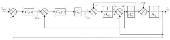
Figure 2.
Structure diagram of the control system for single-phase voltage source LCL-type converter.
Considering the worst case, that is, ignore the parasitic resistance of filter inductance and capacitor.
For LCL filter, there is the following transfer function matrix
where A11, A12, A21 and A22 can be expressed as
According to Equations (2)–(5), when igref = 0, the output impedance Zo(s) of the Norton equivalent circuit of LCL-type grid-tie converter can be deduced; and when uPCC = 0, the current source io(s) of the Norton equivalent circuit of LCL-type grid-connected converter can be deduced, as shown in Equations (6) and (7), respectively. Norton equivalent circuit of LCL-type grid-tie converter is shown in Figure 3.
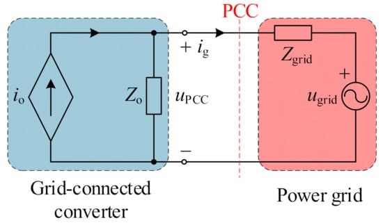
Figure 3.
Norton equivalent circuit of grid-tie converter.
The output impedance model of LCL-type grid-tie converter can be obtained from Equations (6) and (7), as shown in Figure 4.
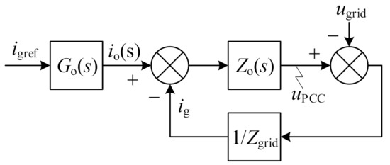
Figure 4.
Output impedance model of LCL-type grid-tie converter.
2.2. Output Impedance Model Considering the Dead-Time Delay Effects and the Digital Control Delay
In order to improve the accuracy of the obtained output impedance model of the grid-connected converter, the digital control delay and dead-time effects should be considered.
The digitally controlled system of the grid-connected converter contains calculation and pulse width modulation (PWM) delays. The calculation delay is a sampling cycle in the standard synchronous sampling approach, and it is modeled as e−sTs in the s-domain, where Ts is the sampling cycle. The pulse width modulation delay can be approximated as e−0.5sTs caused by the zero-order hold. Therefore, the total control delay is approximately one and a half sampling cycles. The expression of the transfer function of the total control delay is shown as Equation (8) [31].
The output impedance and current source of the Norton equivalent circuit of LCL grid-connected converter considering digital control delay are shown in Equations (9) and (10), respectively.
As power electronics have a finite turn-on and turn-off time, a dead-time needs to be set to prevent two switching devices in the same bridge arm from conducting simultaneously. The direction of current flowing from the converter to the utility grid is defined as a positive direction (iinv > 0), and the opposite direction of current is defined as a negative direction (iinv < 0). When iinv < 0, the current flows through IGBTs T2 and T3 when T2 and T3 are on, as shown in Figure 5a; the current flows through power diodes D1 and D4 when T2 and T3 are off, as shown in Figure 5b.
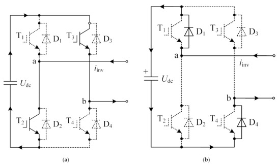
Figure 5.
Schematic diagram of the converter when iinv < 0: (a) The configuration and channel current of the grid-connected converter when T2 and T3 are on; (b) The configuration and channel current of the grid-connected converter when D1 and D4 are on.
The gate signals waveform, output voltage waveform of the converter and error voltage waveform for iinv > 0 are shown in Figure 6. In the figure, UT and UD are conduction voltage drops of the IGBTs and the power diodes, respectively; Ts, td, Ton, and Toff are the switching cycle, dead-time, on-cycle and off-cycle of power electronic devices, respectively; ton and toff are the turn-on time and turn-off time of power electronic devices. uIG1,4 and uIG2,3 are the desirable gate signal of IGBTs T1T4 and T2T3, respectively; uRG1,4 and uRG2,3 are the actual gate signal of IGBTs T1T4 and T2T3 considering the dead-time, respectively; uIab is the desirable output voltage of the converter; uR1ab is the actual output voltage of the converter considering td; uR2ab is the actual output voltage of the converter considering td, ton and toff; uR3ab is the actual output voltage of the converter considering td, ton, toff, UT and UD. une is the error voltage, expressed as une = uR3ab − uIab.
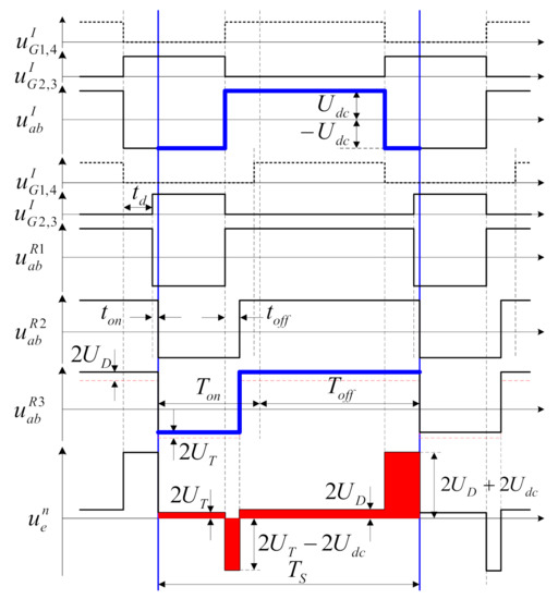
Figure 6.
The gate signals waveform, output voltage waveform of the grid-connected converter and error voltage waveform for iinv < 0.
The average error voltage can be obtained averaged over one switching cycle, shown in Equation (11).
where
In Equation (12), ur is the sinusoidal modulation signal. In Equation (13), Ucm is the triangular carrier wave amplitude. Note that the second term of (11) can be ignored due to being an approximately identical in value to UT and TD in the practical system. Therefore, the closed loop control structure block diagram of the converter considering dead-time effects and digital control delay can be obtained as shown in Figure 7.
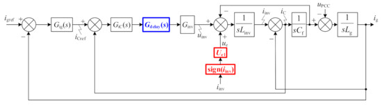
Figure 7.
The closed loop control structure block diagram of the converter considering dead-time effects and digital control delay.
It can be seen from Equation (11), the average error voltage can be seen as a disturbance with a constant amplitude, and the direction is determined by the output current of the converter, i.e., sign(iinv). The disturbance can be expressed as a controlled voltage source ud(s)
Ud(s) can be expressed as
As the control system does not detect the output current iinv of the converter, which can be substituted by ig based on the transfer function relationship of the input and output current of the LCL filter, that is
G(s) can be expressed as
The digital control delay and dead-time effects analyzed above are introduced into the equivalent impedance model of the closed-loop control system of LCL-type grid-connected converter, as shown in Figure 8. In the figure, the equivalent current gain transfer function Go_delay(s) and equivalent output impedance transfer function Zo_delay(s) are shown in Equations (9) and (10), respectively. This output impedance model is valid and is closer to the actual converter system than the models shown in Figure 3 and Figure 4.
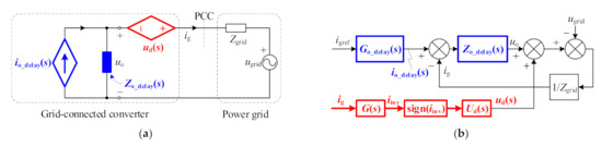
Figure 8.
The equivalent impedance model considering dead-time delay effects and digital control delay: (a) Norton equivalent circuits; (b) Output-impedance model.
Go_delay(s) and Zo_delay(s) compared with the previous Go(s) and Zo(s) are shown in Equations (7) and (6), respectively, the main difference lies in the digital control delay transfer function Gdelay(s), but it has nothing to do with the dead-time effects transfer function ud(s). Therefore, the digital control delay will affect the accuracy of Go_delay(s) and Zo_delay(s), and the dead-time effects are just equivalent to superposing a disturbance voltage ud(s) with constant amplitude and the direction determined by the current direction flowing through the filter inductor Linv at the PCC of the original equivalent output impedance model.
2.3. Simulation Analysis
To verify the correctness and effectiveness of the output impedance model of a single-phase LCL-type grid-connected converter (Figure 8), it is simulated in PSIM and compared with the switching model (Figure 1) in time domain and frequency domain. Parameters of the single-phase LCL-type grid-connected converter are listed in Table 1. The grid-connected current of the switching model and output impedance model are expressed as igs and igo, respectively. The power grid voltage is injected with harmonic components when the time is 0.04 s, including the 5th, 7th, 11th, 13th, 17th, and 19th harmonics, and their magnitudes are 6%, 5%, 3.5%, 3%, 2%, and 1.5% concerning the fundamental part, respectively.

Table 1.
Parameters of LCL-type grid-connected converter system.
The time domain waveform of grid-connected current and its harmonic spectrum of the two models are shown in Figure 9.
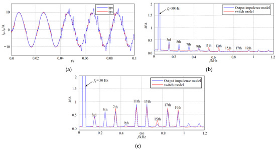
Figure 9.
Comparison of grid-connected current between two models of the converter: (a) Time domain waveform of grid-connected current of the two models; (b) Current spectrum under normal power grid; (c) Current spectrum under distorted power grid.
It can be seen from Figure 9 that the time domain waveforms of the grid-connected current of the two models are almost identical. It can be found from the frequency domain analysis that the two models are almost the same, except that the harmonic content of the grid-connected current of the switching model is slightly higher than that of the output impedance model due to the pulse width modulation. It can be said that the established output impedance model is correct, whether operating in the ideal power grid or distorted power grid, based on the previous theoretical analysis and simulation results. The output impedance model is equivalent to the switching model when the switching ripple caused by PWM modulation is not considered.
3. Output Impedance Modeling for Converter Cluster
The structure of the LCL-type grid-connected converter cluster system in a weak power grid is shown in Figure 10. In this figure, n is the number of converters in the cluster; igrid is the total grid-connected current of the converter cluster; upcc is the point of common coupling voltage of converter cluster; udci is the DC bus voltage of the ith converter; uinvi is the output voltage of the ith converter; ugi is the grid interface voltage of the ith converter; Linvi, Cfi, and Lgi are the filter inductor of the converter side, filter capacitor, and filter inductor of the grid side of the ith converter, respectively; iinvi, iCi and igi are converter side current, filter capacitor current and grid side current of the ith converter; i = 1, 2, ···, n. Gig(s) is the transfer function of grid-connected current outer loop controller; GiC(s) is capacitor-current internal loop controller transfer function.
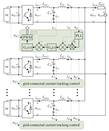
Figure 10.
Structure of converter cluster system.
According to the output impedance model of the converter, the converter cluster system shown in Figure 10 can be simplified to the impedance structure shown in Figure 11. In this figure, igrefi is the grid current reference signal of the ith converter; Goi(s) is the current gain transfer function of the ith converter; Zoi(s) is the output impedance transfer function of the ith converter. For the convenience, the impedance network shown in Figure 11 is simplified into an equivalent admittance network, as shown in Figure 12. Compared with the converter switching model, its output impedance model can significantly reduce the amount of calculation in the process of software simulation analysis and design and shorten the simulation time. It is especially suitable for the study of the interaction between converter cluster and power grid.
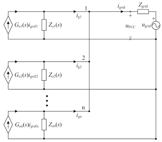
Figure 11.
Impedance structure of converter cluster system.
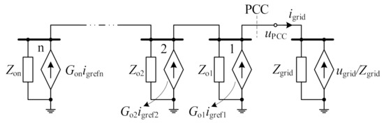
Figure 12.
Impedance network of converter cluster system based on Norton equivalent circuit.
Taking the first grid-connected converter as an example, the expressions of output current ig1 and PCC voltage uPCC can be derived by using the node voltage method for the equivalent admittance network shown in Figure 12, as shown in Equations (19) and (20), respectively.
To obtain the output current expression of the first converter in the converter cluster system by substituting Equation (20) into Equation (19).
According to Equation (21), the output current ig1 of the converter is jointly determined by its own output current given signal igref1, output current given signal igrefj of other converters and power grid voltage ugrid. The characteristics of impedance network R11(s), impedance network R1j(s) and impedance network R1g(s) affect the output current ig1. The impedance network R11(s) shows the coupling between the given output current signal igref1 and output current ig1 of the converter itself. Impedance network R1j(s) shows the coupling between the output current given signal igrefj of all other converters and output current ig1. The impedance network R1g(s) shows the coupling between the power grid voltage ugrid and output current ig1.
Similarly, expressions of the grid-connected current of other converters in the cluster can be obtained, thus the matrix expression of the grid-connected current of the converter cluster system can be written as:
In general, the converters in the converter cluster are usually from the same manufacturer, so the hardware parameters and controller structure parameters of each converter are the same. To simplify the analysis, assuming that each grid-connected converter is identical, but the output current given signal of each converter is different, Equations (21) and (22) can be simplified as shown in Equations (23) and (24), respectively.
It can be seen from Equations (23) and (24) that complex coupling exists in the converter cluster system. According to Equation (23), when the power grid impedance is zero, R12(s) = 0, and all non-diagonal elements of the impedance matrix in Equation (24) are zero, that is, the coupling between all converters in the converter cluster disappears. It can also be seen from the converter cluster system shown in Figure 12 that when the power grid impedance is zero, the voltage at PCC is identical to the power grid voltage. In this case, any grid-connected converter operates independently and has no influence on each other. In summary, the interaction effect in the converter cluster system is coupled by the power grid impedance.
Assuming that the output current given signal of any converter in the cluster is also the same, the converter cluster system shown in Figure 12 can be further simplified into the single converter grid-connected system shown in Figure 13.
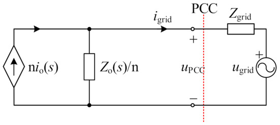
Figure 13.
Simplified equivalent impedance network of converter cluster system.
Figure 13 shows that the converter cluster system can be equivalent to a single converter system, in which the current source io(s) is increased to n times the original current and the output impedance Zo(s) is reduced to 1/n of the original impedance. According to the superposition principle, the total output current igtotal of the converter cluster can be deduced as follows from Figure 13.
When the hardware parameters, control methods, and output current given signals of all grid-connected converters are precisely the same, the total output current of the converter cluster composed of n converters is equivalent to n times the grid-connected current of a single converter under the condition that the grid impedance increases n times.
4. Combined Harmonic Suppression Strategy
According to the analysis in Section 2, the dead-time effects do not affect the accuracy of the output impedance, they are only equivalent to superimposing a disturbance voltage on the original output impedance model. Therefore, the following analysis only considers the digital control delay. The ability of the grid-connected converter to suppress harmonics on the grid side mainly depends on the frequency characteristics of output impedance. If the amplitude of the output impedance Zo(S) in the whole frequency range is larger (the ideal case is infinite), the suppression effect will be better. The full feedforward control of the power grid voltage feeds full power grid voltage forward to the output end of the power grid current controller to suppress the harmonic of power grid voltage. It should be emphasized that the feedforward control does not affect the closed-loop current tracking performance of the grid-tie converter. The control system of LCL grid-tie converter (including power grid voltage full feedforward control) is shown in Figure 14. In the figure, GV_ff (s) is the feedforward coefficients.
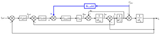
Figure 14.
Structure diagram of grid-tie converter considering power grid voltage full feedforward control.
The output impedance of LCL grid-tie converter can be deduced from Figure 14, which can be expressed as
It can be seen from Equation (26) that for grid-tie converter, if the influence of harmonics on the grid current is to be completely eliminated, the output impedance amplitude can be realized to be infinite through the power grid voltage feedforward control, that is, the denominator of Equation (26) is zero, so the feedforward coefficient should be:
As can be seen from Equation (27), GV_ff (s) is a second-order differential transfer function; it is then easy to introduce high-frequency noise interference into the control system. In this case, the power grid voltage can be low-pass filtered before the feedforward algorithm is implemented. As the use of low pass filter will cause a certain degree of distortion of the grid voltage, so the output impedance amplitude cannot be infinite. Considering that voltage harmonics below 2 kHz frequency (within 40 times power frequency harmonics frequency) of the power grid are mainly concerned, then TLPF = 40 μs (corresponding cut-off frequency is about 3980 Hz) is taken in this paper. The complete feedforward coefficient after adding the first-order low-pass filter is:
The power grid mainly contains low-frequency odd harmonics, and the low-frequency harmonics caused by the nonlinearity of the grid-connected converter are also mainly odd. Therefore, multi-resonance control can also suppress the low-frequency odd harmonics of the incoming current. The transfer function of the multi-resonance controller is:
where m is the number of harmonics and Km is the resonance coefficient of the multi-resonance controller; ωc is the bandwidth frequency; ωg is the fundamental frequency of the power grid voltage. Km = 16.7 s−1, ωc = 10 rad/s, ωg = 314 rad/s are taken in this paper.
In this paper, the improved full feedforward of power grid voltage and multi-resonance control are combined to form a combined harmonic suppression strategy. The system structure of the LCL-type grid-tie converter is shown in Figure 15.
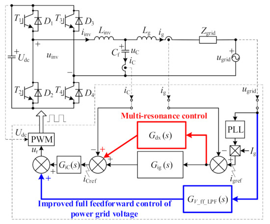
Figure 15.
Control structure of Grid-connected Converter (used combined harmonic suppression strategy).
To sum up, the Bode diagram of the output impedance of the grid-connected converter, using or not using the combined harmonic suppression strategy, can be drawn as shown in Figure 16.
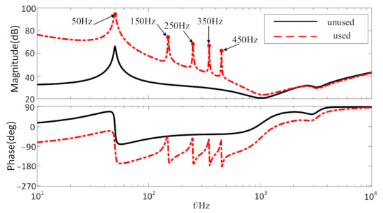
Figure 16.
Bode diagram of output impedance used or unused combined harmonic suppression strategy.
Figure 16 shows that the output impedance amplitude of the LCL-type grid-tie converter through the feedforward control in the whole low frequency is significantly improved, and the multi-resonance control presents high impedance characteristics in specific harmonic frequency. Therefor the proposed combined harmonic suppression strategy can be implemented more effectively to suppress harmonics.
5. Simulation Analysis of Harmonic Interaction between Converter Cluster and Power Grid
To verify the suppression effect of the combined harmonic suppression strategy on the harmonic interaction between the converter cluster and power grid, the grid-connected system of the converter cluster (composed of 10 identical converters, system parameters of the converter are listed in Table 1) is simulated. The power grid voltage is injected with harmonic components to simulate voltage distortions, including the 5th, 7th, 11th, 13th, 17th, and 19th harmonics, and their magnitudes concerning the fundamental part are 2%, 2%, 1.5%, 1.5%, 1%, and 1%, respectively.
The harmonic interactive simulation waveform between the converter cluster and the power grid under the condition of the distorted power grid voltage (combined harmonic suppression is unused) is shown in Figure 17.
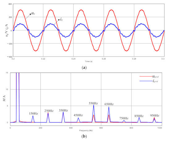
Figure 17.
Waveforms of grid voltage and grid-tie current under the distorted power grid (without using combined harmonic suppression): (a) Time domain waveform of grid voltage and grid-tie current; (b) Spectrum of grid voltage and grid-tie current.
In a case where the power grid voltage contains harmonics, as shown in Figure 17, the grid-tie current distortion is serious as the converter cluster and the power grid both contain harmonic excitation sources close to this quasi-resonant frequency. Harmonic current amplitudes of 450 Hz (9th power frequency), 550 Hz (11th power frequency), 650 Hz (13th power frequency) and 750 Hz (15th power frequency) are amplified, of which 550 Hz (11th power frequency) and 650 Hz (13th power frequency) are amplified most seriously.
When the combined harmonic suppression strategy is introduced, the harmonic interaction simulation waveform between the converter cluster and the grid under the condition of distorted grid voltage is shown in Figure 18.
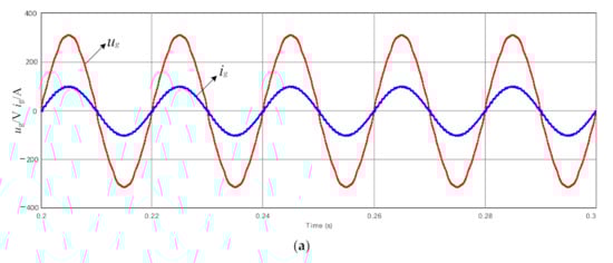
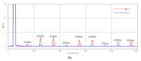
Figure 18.
Waveforms of grid voltage and grid-tie current under a distorted power grid (combined harmonic suppression is used): (a) Time domain waveform of grid voltage and grid-tie current; (b) Spectrum of grid voltage and grid-tie current.
By comparing Figure 17 and Figure 18, it can be concluded that when the combined harmonic suppression strategy is introduced, the amplitude of all harmonics currents below and equal to the 19th in the low-frequency range is suppressed. It can be concluded that the strategy can well suppress harmonic interaction resonance.
6. Conclusions
An output impedance model of the single-phase LCL-type grid-tie converter, considering the computation and the PWM delay and the dead-time delay effects, is derived in this paper. The simulation verifies the validity of the output impedance model and is in tune with the switching model, even under the intense distortions grid voltage situation. Based on the output impedance model, harmonic interaction between the converter cluster and the power grid are modeled and analyzed. A combined harmonic suppression strategy is incorporated into every converter control scheme to suppress the harmonic interaction. Simulation results in the PSIM are presented to demonstrate correctness of harmonic interaction analysis and effectiveness of the proposed suppression strategy.
Author Contributions
Conceptualization, X.Z. and D.X.; methodology, X.Z.; software, X.Z.; validation, D.X., Y.H.; formal analysis, D.X.; investigation, X.Z.; resources, X.Z., D.X., Y.H.; writing—original draft preparation, X.Z.; writing—review and editing, D.X., Y.H.; supervision, D.X., Y.H.; project administration, X.Z.; funding acquisition, X.Z. All authors have read and agreed to the published version of the manuscript.
Funding
This work was supported by the Natural Science Foundation of Anhui Provincial Education Department under Grant KJ2021A0864 and Talent Introduction Project of Anhui Science and Technology University under Grant DQYJ201901.
Institutional Review Board Statement
Not applicable.
Informed Consent Statement
Not applicable.
Data Availability Statement
Not applicable.
Conflicts of Interest
The authors declare no conflict of interest.
References
- Li, X.; Wang, L.; Yan, N.; Ma, R. Cooperative Dispatch of Distributed Energy Storage in Distribution Network with PV Generation Systems. IEEE Trans. Appl. Supercond. 2021, 31, 1–4. [Google Scholar] [CrossRef]
- Tan, Y.; Wang, Z. Incorporating Unbalanced Operation Constraints of Three-Phase Distributed Generation. IEEE Trans. Power Syst. 2019, 34, 2449–2452. [Google Scholar] [CrossRef]
- Kou, G.; Chen, L.; VanSant, P.; Velez-Cedeno, F.; Liu, Y. Fault Characteristics of Distributed Solar Generation. IEEE Trans. Power Deliv. 2020, 35, 1062–1064. [Google Scholar] [CrossRef]
- Fathabad, A.M.; Cheng, J.; Pan, K.; Qiu, F. Data-Driven Planning for Renewable Distributed Generation Integration. IEEE Trans. Power Syst. 2020, 35, 4357–4368. [Google Scholar] [CrossRef]
- Wang, Q.; Qin, W.; Han, X.; Wang, P.; Wang, L.; Zhang, Y. Robustness evaluation for harmonic suppression of LCL-type converter based on converter-side current feedback strategy under weak and distorted grid. CPSS Trans. Power Electron. Appl. 2021, 6, 166–177. [Google Scholar] [CrossRef]
- Tang, X.; Chen, W.; Zhang, M. A Current Decoupling Control Scheme for LCL-Type Single-Phase Grid-Connected Converter. IEEE Access 2020, 8, 37756–37765. [Google Scholar] [CrossRef]
- Long, B.; Lu, P.J.; Chong, K.T.; Rodriguez, J.; Guerrero, J.M. Robust Fuzzy-Fractional-Order Nonsingular Terminal Sliding-Mode Control of LCL-Type Grid-Connected Converters. IEEE Trans. Ind. Electron. 2022, 69, 5854–5866. [Google Scholar] [CrossRef]
- Zhu, D.; Zhou, S.; Zou, X.; Kang, Y. Improved Design of PLL Controller for LCL-Type Grid-Connected Converter in Weak Grid. IEEE Trans. Power Electron. 2020, 35, 4715–4727. [Google Scholar] [CrossRef]
- Liu, Q.; Caldognetto, T.; Buso, S. Review and comparison of grid-tied inverter controllers in microgrids. IEEE Trans. Power Electron. 2020, 35, 7624–7639. [Google Scholar] [CrossRef]
- Peng, Q.; Jiang, Q.; Yang, Y.; Liu, T.; Wang, H.; Blaabjerg, F. On the stability of power electronics-dominated systems: Challenges and potential solutions. IEEE Trans. Ind. Appl. 2019, 55, 7657–7670. [Google Scholar] [CrossRef]
- Wang, X.; Blaabjerg, F. Harmonic stability in power electronic based power systems: Concept, modeling, and analysis. IEEE Trans. Smart Grid 2019, 10, 2858–2870. [Google Scholar] [CrossRef] [Green Version]
- Saleem, M.; Choi, K.; Kim, R. Resonance damping for an LCL filter type grid-connected inverter with active disturbance rejection control under grid impedance uncertainty. Electr. Power Energy Syst. 2019, 109, 444–454. [Google Scholar] [CrossRef]
- Shuai, Z.; Liu, D.; Shen, J.; Tu, C.; Cheng, Y.; Luo, A. Series and parallel resonance problem of wideband frequency harmonic and its elimination strategy. IEEE Trans. Power Electron. 2014, 29, 1941–1952. [Google Scholar] [CrossRef]
- Lu, M.; Wang, X.; Loh, P.C.; Blaabjerg, F. Resonance interaction of multiparallel grid-connected inverters with LCL filter. IEEE Trans. Power Electron. 2017, 32, 894–899. [Google Scholar] [CrossRef]
- Kwon, J.; Wang, X.; Blaabjerg, F.; Bak, C.L.; Sularea, V.-S.; Busca, C. Harmonic interaction analysis in a grid-connected converter using harmonic state-space (HSS) modeling. IEEE Trans. Power Electron. 2017, 32, 6823–6835. [Google Scholar] [CrossRef] [Green Version]
- He, B.; Chen, W.; Mu, H.; Zhan, D.; Zhang, C. Small-Signal Stability Analysis and Criterion of Triple-Stage Cascaded DC System. IEEE J. Emerg. Sel. Top. Power Electron. 2022, 10, 2576–2586. [Google Scholar] [CrossRef]
- Pan, P.; Chen, W.; Shu, L.; Mu, H.; Zhang, K.; Zhu, M.; Deng, F. An Impedance-Based Stability Assessment Methodology for DC Distribution Power System with Multivoltage Levels. IEEE Trans. Power Electron. 2020, 35, 4033–4047. [Google Scholar] [CrossRef]
- Rashidirad, N.; Hamzeh, M.; Sheshyekani, K.; Afjei, E. A simplified equivalent model for the analysis of low-frequency stability of multi-bus DC micro-grids. IEEE Trans. Smart Grid 2018, 9, 6170–6182. [Google Scholar] [CrossRef]
- Saleem, M.; Ko, B.-S.; Kim, S.-H.; Kim, S.-I.; Chowdhry, B.S.; Kim, R.-Y. Active Disturbance Rejection Control Scheme for Reducing Mutual Current and Harmonics in Multi-Parallel Grid-Connected Inverters. Energies 2019, 12, 4363. [Google Scholar] [CrossRef] [Green Version]
- Feng, G.; Ye, Z.; Xia, Y.; Huang, L.; Wang, Z. Impedance Modeling and Stability Analysis of Three-Phase Four-Wire Inverter with Grid-Connected Operation. Energies 2022, 15, 2754. [Google Scholar] [CrossRef]
- Song, S.; Guan, P.; Liu, B.; Lu, Y.; Goh, H. Impedance Modeling and Stability Analysis of DFIG-Based Wind Energy Conversion System Considering Frequency Coupling. Energies 2021, 14, 3243. [Google Scholar] [CrossRef]
- Zhou, W.; Torres-Olguin, R.E.; Zadeh, M.K.; Bahrani, B.; Wang, Y.; Chen, Z. Electromagnetic Oscillation Origin Location in Multiple-Inverter-Based Power Systems Using Components Impedance Frequency Responses. IEEE Open J. Ind. Electron. Soc. 2021, 2, 1–20. [Google Scholar] [CrossRef]
- Tao, H.; Hu, H.; Wang, X.; Blaabjerg, F.; He, Z. Impedance-based harmonic instability assessment in a multiple electric trains and traction network interaction system. IEEE Trans. Ind. Appl. 2018, 54, 5083–5096. [Google Scholar] [CrossRef]
- Hu, H.; Tao, H.; Blaabjerg, F.; Wang, X.; He, Z.; Gao, S. Train-network interactions and stability evaluation in high-speed railways—Part I: Phenomena and modeling. IEEE Trans. Power Electron. 2018, 33, 4627–4642. [Google Scholar] [CrossRef]
- Enslin, J.H.R.; Heskes, P.J.M. Harmonic interaction between a large number of distributed power inverters and the distribution network. IEEE Trans. Power Electron. 2004, 19, 1586–1593. [Google Scholar] [CrossRef]
- Lu, M.; Wang, X.; Blaabjerg, F. An analysis method for harmonic resonance and stability of multi-paralleled LCL-filtered inverters. In Proceedings of the IEEE 6th International Symposium on Power Electronics for Distributed Generation Systems (PEDG), Aachen, Germany, 22–25 June 2015. [Google Scholar]
- Cao, W.; Wang, S.; Kang, H.; Liu, K.; Wang, Q.; Zhao, J. Inherent Interaction Analysis for Harmonic Oscillations in the Multi-Paralleled Grid-Connected Inverter System Using a Sum Type Criterion: Global Admittance (GA). IEEE Access 2020, 8, 8275–8285. [Google Scholar] [CrossRef]
- He, Y.; Wang, X.; Ruan, X.; Pan, D.; Qin, K. Hybrid active damping combining capacitor current feedback and point of common coupling voltage feedforward for LCL-type grid-connected inverter. IEEE Trans. Power Electron. 2021, 36, 2373–2383. [Google Scholar] [CrossRef]
- Wang, X.; He, Y.; Qin, K.; Zhang, H.; Pan, D.; Ruan, X.; Zhou, Q.; Yao, C. Impact of Controller Saturation on Instability Behavior of Grid-Connected Inverters. IEEE Trans. Power Electron. 2022, 37, 7739–7750. [Google Scholar] [CrossRef]
- Li, Y.W.; Blaabjerg, F.; Vilathgamuwa, D.M.; Loh, P.C. Design and Comparison of High Performance Stationary-Frame Controllers for DVR Implementation. IEEE Trans. Power Electron. 2007, 22, 602–612. [Google Scholar] [CrossRef]
- Zhang, X.; Spencer, J.W.; Guerrero, J.M. Small-Signal Modeling of Digitally Controlled Grid-Connected Inverters with LCL Filters. IEEE Trans. Ind. Electron. 2013, 60, 3752–3765. [Google Scholar] [CrossRef] [Green Version]
Publisher’s Note: MDPI stays neutral with regard to jurisdictional claims in published maps and institutional affiliations. |
© 2022 by the authors. Licensee MDPI, Basel, Switzerland. This article is an open access article distributed under the terms and conditions of the Creative Commons Attribution (CC BY) license (https://creativecommons.org/licenses/by/4.0/).