Article

A Numerical Study on the Effects of the Geometry and Location of an Inserted Wire on Methane–Air Flames in a Micro–Burner

by
Jalal Zarvandi
1,
Mohammadreza Baigmohammadi
2,* and
Sadegh Tabejamaat
1
1
Amirkabir Combustion Laboratory (ACL), Department of Aerospace Engineering, Amirkabir University of Technology (Tehran Polytechnic), Hafez Ave., Tehran 15875-4413, Iran
2
Power & Flow Group, Department of Mechanical Engineering, Eindhoven University of Technology, 5612 AZ Eindhoven, The Netherlands
*
Author to whom correspondence should be addressed.
Energies 2022, 15(1), 93; https://doi.org/10.3390/en15010093
Submission received: 23 November 2021 / Revised: 18 December 2021 / Accepted: 21 December 2021 / Published: 23 December 2021
(This article belongs to the Section I1: Fuel)

Abstract

:
The effects of the diameter and location of an inserted wire on methane–air flame characteristics in a micro-burner, with a backward-facing step, were investigated numerically. Our goal was to shed light on the parameters that the authors had not already considered in the previous study. To do so, the effects of the studied parameters on the flame location and distribution of temperature, H, and OH species, were scrutinized. It was shown that increasing the inserted wire’s diameter and relocating the inserted wire towards the outlet had polynomial and linear effects on the flame location in the burner, respectively. Although changing these two parameters did not have any obvious effects on the maximum temperature of the auxiliary axis in the burner or the external wall, effects on the peak values of the hot-flame critical chemical species of OH and H were recognized. Furthermore, it was shown that the temperature distribution on the outer surface of the burner was more influenced by the wire’s axial location in the burner, rather than the wire’s diameter. This effect may be of interest for designing micro-TPVs or micro-TEGs.

1. Introduction

The efficient combustion of low-carbon fuels, including low-calorific value biogases and flare gases in micro-combustors (e.g., micro-thermophotovoltaics (mTPVs) [1], micro gas turbines, micro-thermoelectric generators (mTEGs) [2], etc.) is a promising approach towards the development of low-to-zero-emission portable energy devices. The burning of waste flammable gases which are high in methane content as a major greenhouse gas (GHG), could convert the gases into water vapor and carbon dioxide, which is relatively (about 25 times) less harmful than methane in terms of global warming [3]. Moreover, a significant amount of thermal energy would be released during the process, which could be applied in power generation and heating purposes. Furthermore, during the burning process, the generated carbon dioxide could be captured using novel carbon dioxide storage/conversion techniques [4]. Although the above-mentioned cycle seems to be promising, the efficient combustion of low-carbon, low-calorific value fuels in small-scale combustors is still a critical challenge that should be completely overcome using efficient, pragmatic, and low-cost approaches. In this regard, several different approaches, such as using the backward-facing step [5], a catalyst [6], adding hydrogen, the Swiss-roll design [7], etc., have been proposed, and are being investigated by many researchers. In this way, the combustion characteristics of methane– and propane–air/oxygen in micro- and meso-scale burners with backward-facing steps, and blending methane with hydrogen, have been widely investigated experimentally and numerically by Baigmohammadi et al. [8,9,10,11]. In these studies, it was reported that the backward-facing step and adding hydrogen are two efficient approaches that could extend the flame presence limits of various flames in a small-sized combustor. However, using hydrogen as an additive in such a small-scale combustor is not an easy task, due to hydrogen’s superior diffusivity and flammability. Furthermore, increasing the heat transfer rate from the post-flame zone to the preheating zone in a micro-combustor through its wall is another promising technique that could extend flame stability in such small-scale combustors. Although increasing the combustor’s wall thermal conductivity could facilitate heat recirculation between the post and the preheating flame zones in a micro-combustor, it will increase heat loss rate to the ambient as well. This may suppress the flame presence range in the combustor. In this regard, increasing the heat transfer rate from the post flame to the preheating zone using a central highly conductive wire has been already proposed by Baigmohammadi et al. [8]. It was shown that using such a central highly conductive ceramic can not only intensify the heat recirculation between the post- and the pre-heating regions in a premixed micro-combustor, but it also has no effect on the heat loss rate. Therefore, it seems that this technique could be counted as a simple and low-cost approach for extending the flame presence range of less reactive fuels in micro-combustors. Hence, further investigations into the effects of some geometrical parameters, including the wire diameter and its axis location on the flame presence range in the proposed micro-combustor, would be an interesting topic that has not already been considered by Baigmohammadi et al. [8]. In this regard, further analyses about the effects will be presented and discussed in the following sections, with detail.

2. Numerical Approach and Boundary Conditions

The geometry of the studied micro-burner is demonstrated in Figure 1. In this burner/combustor, the combustible premixed methane–air flows from left to right. Therefore, the origin of coordinates of the geometry is placed at the far-left side and the geometry’s centerline. As seen, the burner is equipped with a backward-facing step and a centrally inserted wire (0.1 mm in diameter). The inserted wire is initially located at the backward-facing step, 1.50 mm downstream of the burner’s inlet. The flow field in the computational domain is laminar (Re < 200). Due to the axisymmetric geometry of the burner and the laminar flow field, we only modeled half of the burner. Here, we assumed that the flames were axisymmetric, and all effects that may cause asymmetric flames in an axisymmetric geometry were suppressed. This assumption was completely plausible due to the small diameter of the studied burner (1.2 mm), which strongly suppressed the occurrence of hydrodynamic instabilities [12], and the Lewis number close to unity (φ = 0.9) which suppressed thermo-diffusive instabilities in the micro-burner [13]. It is believed that these two mentioned instabilities are mostly responsible for the asymmetric flames in such a small-scale combustor [14,15,16]. In this regard, all the applied values for the study are presented in Table 1. It should be noted that the external emissivity coefficient of 0.2 refers to a value between the emissivity coefficients of weathered stainless steel (~0.85), and a polished one (~0.075). Moreover, the thermal conductivity of 20 W·m−1·K−1 for the burner’s body may refer to some ceramics, such as aluminum oxide or stainless steel. Here, we simulated the inserted wire as an imaginary high-conductive wire that could tolerate high temperatures. It is of interest that the imaginary inserted wire with such a high thermal conductivity may resemble the physical characteristics of some materials such as AlN (aluminum nitride). AlN can withstand the hot flame temperature region, and its thermal conductivity is high [17].
In this study, all of the simulations including solving the laminar Navier–Stokes equations (continuity, momentum in x and r directions, energy, and species conservation) and the combustion chemistry, were performed based on the procedure which has been already discussed in detail by the authors in their previous publications [8,11]. In this regard, the governing equations were solved using a finite-volume numerical scheme. The scheme was developed based on Patankar’s Simpler algorithm developed in a collocated mesh by Rahman et al. [18]. For increasing the precision of the computations, we set the convergence criterion of all considered equations to 10−6. For the brevity of the article, the authors would like to refer to those publications for further information about applied computational schemes.

3. Results and Discussions

The main results of the study, including the mesh study and validation and the effects of the wire’s diameter and its axial location in the burner on the methane–air flame characteristics, have been considered in the following subsections.

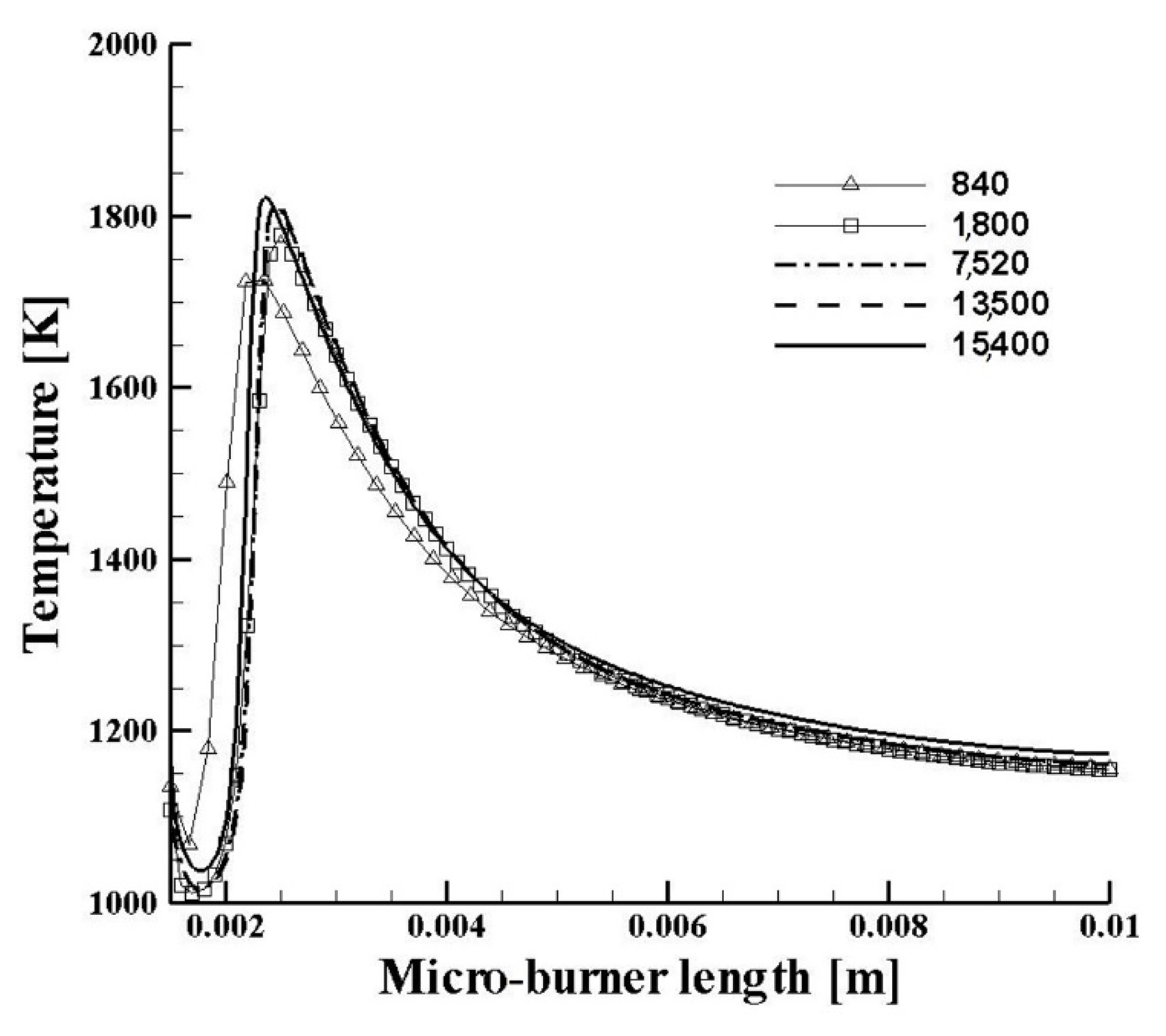
3.1. Mesh Study and Validation

The validity of the applied code and its solvers for completing the simulations is shown in Figure 2. This code and the solvers have been already discussed by the authors [8,11]. It is seen that the applied code can satisfactorily reproduce previously published numerical [6] and experimental [19] data within the maximum deviation of less than 13%. However, the code can accurately predict the measured temperatures within less than ±5%. Moreover, to consider the effect of computational mesh size on the studied parameters, mesh size and number independence study have been performed. As shown in Figure 2, increasing the mesh numbers beyond 7520 has no significant effect on the temperature distribution on the auxiliary axis of r = 0.3 mm in the burner/combustor. Therefore, this mesh size was selected to perform further simulations.

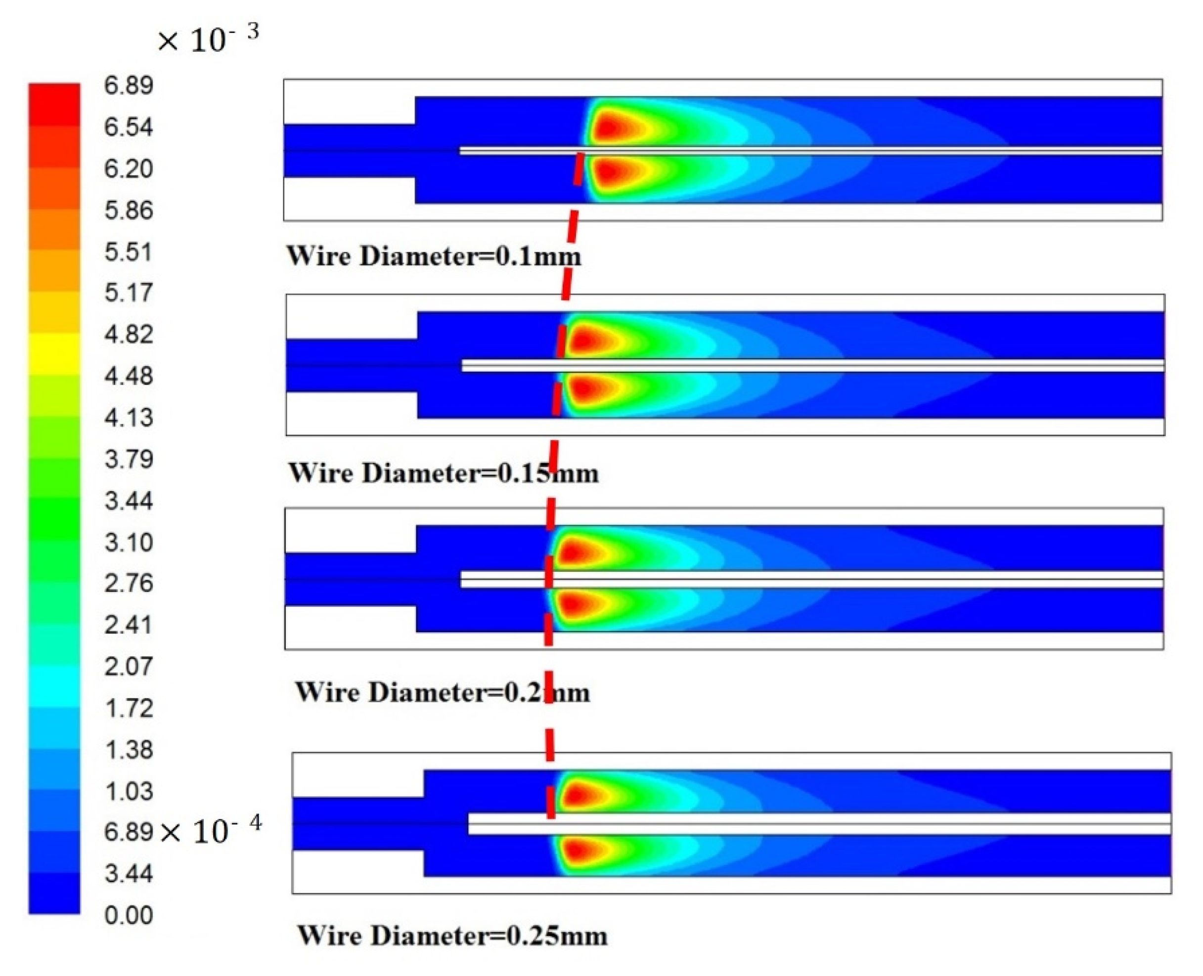
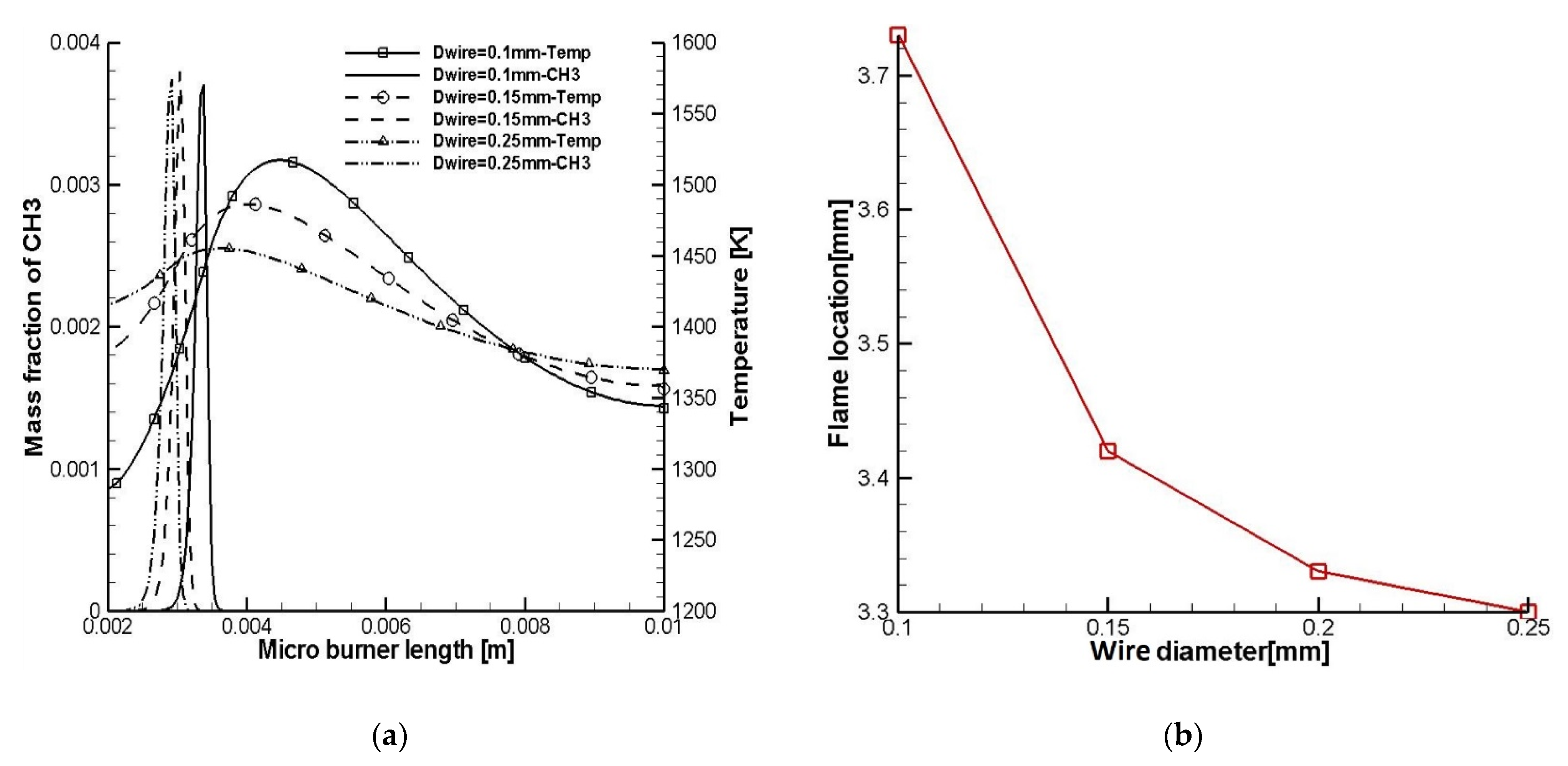
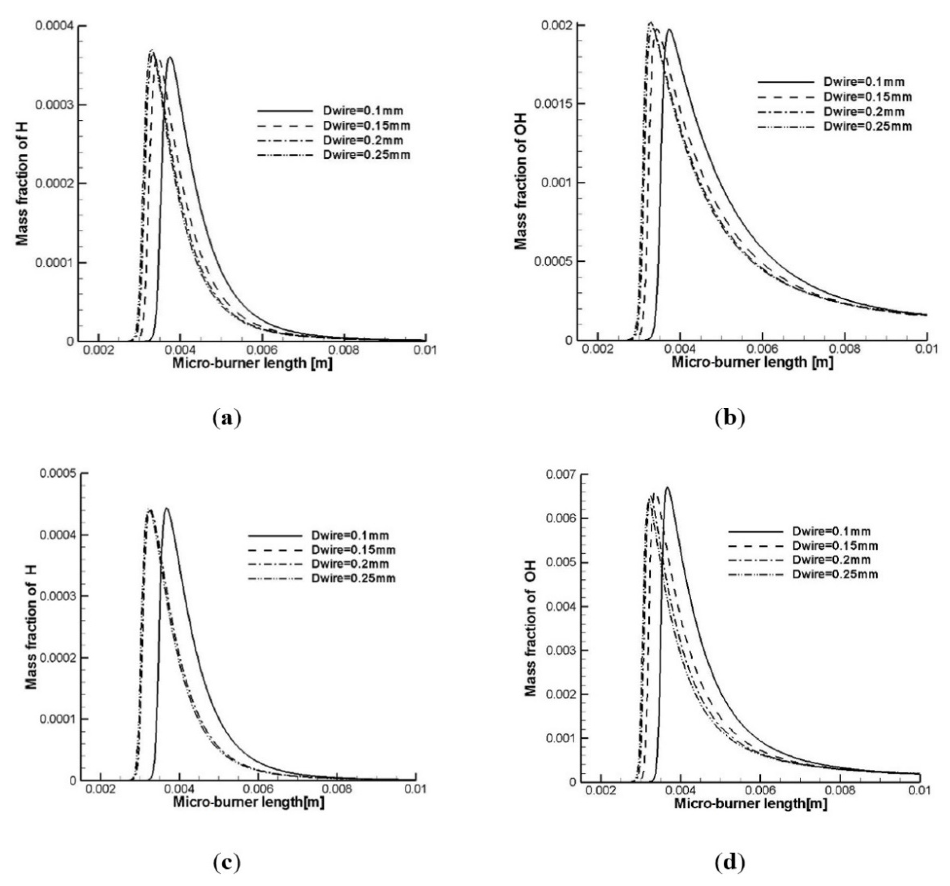
3.2. Effect of the Wire’s Diameter on Flame Characteristics

The effect of the wire’s diameter on flame location in the micro-burner/combustor is shown in Figure 3 and Figure 4. Here, it should be noted that the axial position of the inserted wire for all the considered cases in this section is 2 mm. As seen in these figures, although increasing the wire’s diameter moves the flame location towards the step, and in this way increases the flame’s presence range in the burner/combustor, its effect is not superior (Figure 4b). In this regard, it can be seen in Figure 4a that increasing the wire’s diameter promotes chemical reactions and specifically the formation of ĊH3 radical by increasing the temperature level on the wire’s surface, influenced by the high-temperature post-flame zone. Indeed, increasing the wire’s diameter elevated the heat transfer surface and then the temperature uniformity (less gradient) in the wire, so that the leading tip of thicker wires reached a higher temperature compared with the narrower wires, promoting chemical reactions by providing enough activation energy for some crucial chain branching and chain propagation reactions.
To achieve a better picture of the chemistry of the phenomenon, the chemical flux analyses based on rate of production (ROP) analyses were performed to trace the consumption path of the reactants (here methane) at the different preheating temperatures, just before a sudden rise in CH3 concentration. The consequent temperatures are shown in Figure 4a with their intermediate species. This analysis provides us with an isolated insight into the combustion chemistry at the beginning of the process when the fuel starts to disassociate (H–atom abstraction from CH4) and generate a radical pool for further reactions in the reaction zone. Hence, the analyses were performed in an adiabatic constant volume reactor (to isolate combustion chemistry from the flow field) for each studied case, corresponding to the temperatures in which the methyl radical pool started to build up. In this regard, a Python script code [20] based on the CANTERA [21] was developed and implemented for the analyses using the reduced combustion chemistry model of Smooke et al. [22]. Therefore, the flux analysis of the reactions corresponding to temperature on the leading edge of the outer surface of the inserted wire (the axial position of 0.002 m) shown in Figure 4a was performed for the cases when 20% methane was consumed. We chose the value based on the reactivity of fuel and the applied chemistry model. Indeed, this value should clearly show how methane starts to be dissociated by available active radicals in the reaction zone. Thus, the lower thresholds may show no information about the dissociation, and inversely, the higher ones may find the dissociation almost complete with no information about the process [23]. Thus, this threshold is flexible and could be tuned corresponding to the parameters. As demonstrated in Figure 5, most of the methane was dissociated into methyl radical using H-atom and hydroxyl (ȮH) radicals. As seen in Figure 5, the increasing temperature had no significant effect on changing the participation level (colored percentages) of the reactions (e.g., CH4 + Ḣ → ĊH3 + H2, CH4 + ȮH → ĊH3 + H2O, ĊH3 + Ȯ → CH2O + Ḣ, etc.) in the consumption process of methane. However, the increasing temperature significantly promoted the fluxes of some crucial reactions. These intensified fluxes led to the faster production of critical species such as hydrogen-atom, hydroxyl, and methyl, which build up the radical pool faster in the combustion zone, leading to increased production of the species that facilitate the ignition process, and the flame presence range in the micro-burner/combustor. Such an effect is depicted in Figure 6.
As seen in Figure 6a,b, increasing the wire diameter promotes the production of some active species such as Ḣ and ȮH in the radical pools in the vicinity of the inner wall of the micro-burner/combustor. However, as seen in Figure 6c,d this effect on the radical pool located along the axial line defined at r = 0.3 mm is not obvious. Interestingly, it is demonstrated in Figure 6 that the mass fraction levels of Ḣ and ȮH in the vicinity of the inserted wire (Figure 6c,d) were higher than that near the inner wall (Figure 6a,b).
As shown in Figure 7, this effect is directly related to the difference in the temperature distribution level in the vicinity of the inserted wire (Figure 7b) and the inner wall (Figure 7a). Moreover, Figure 7 demonstrates that although increasing the wire’s diameter influenced the temperature distribution in the micro-burner/combustor, and shifted it towards the backward-facing step accordingly, its effect on the maximum temperature level was minor.

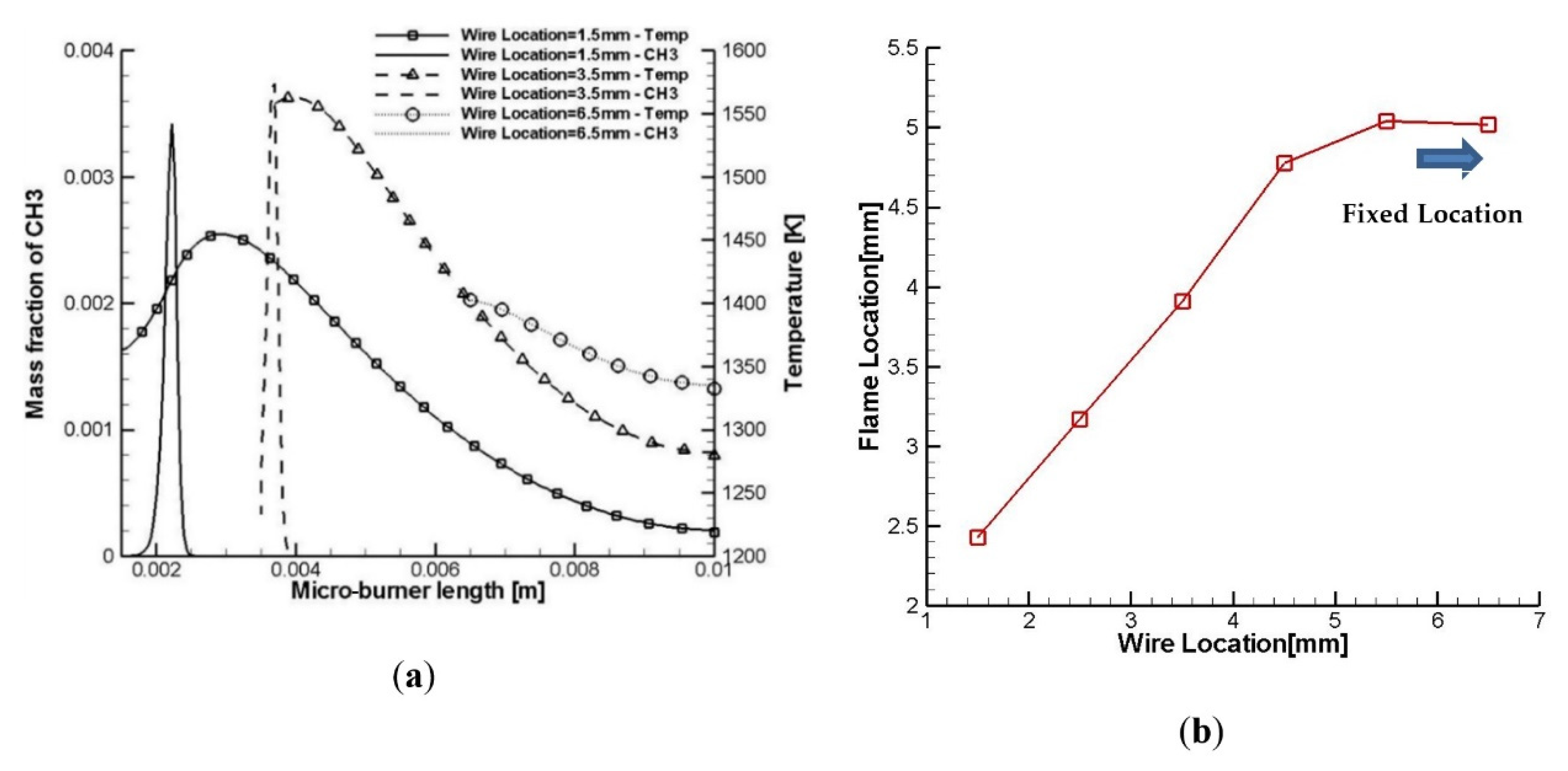
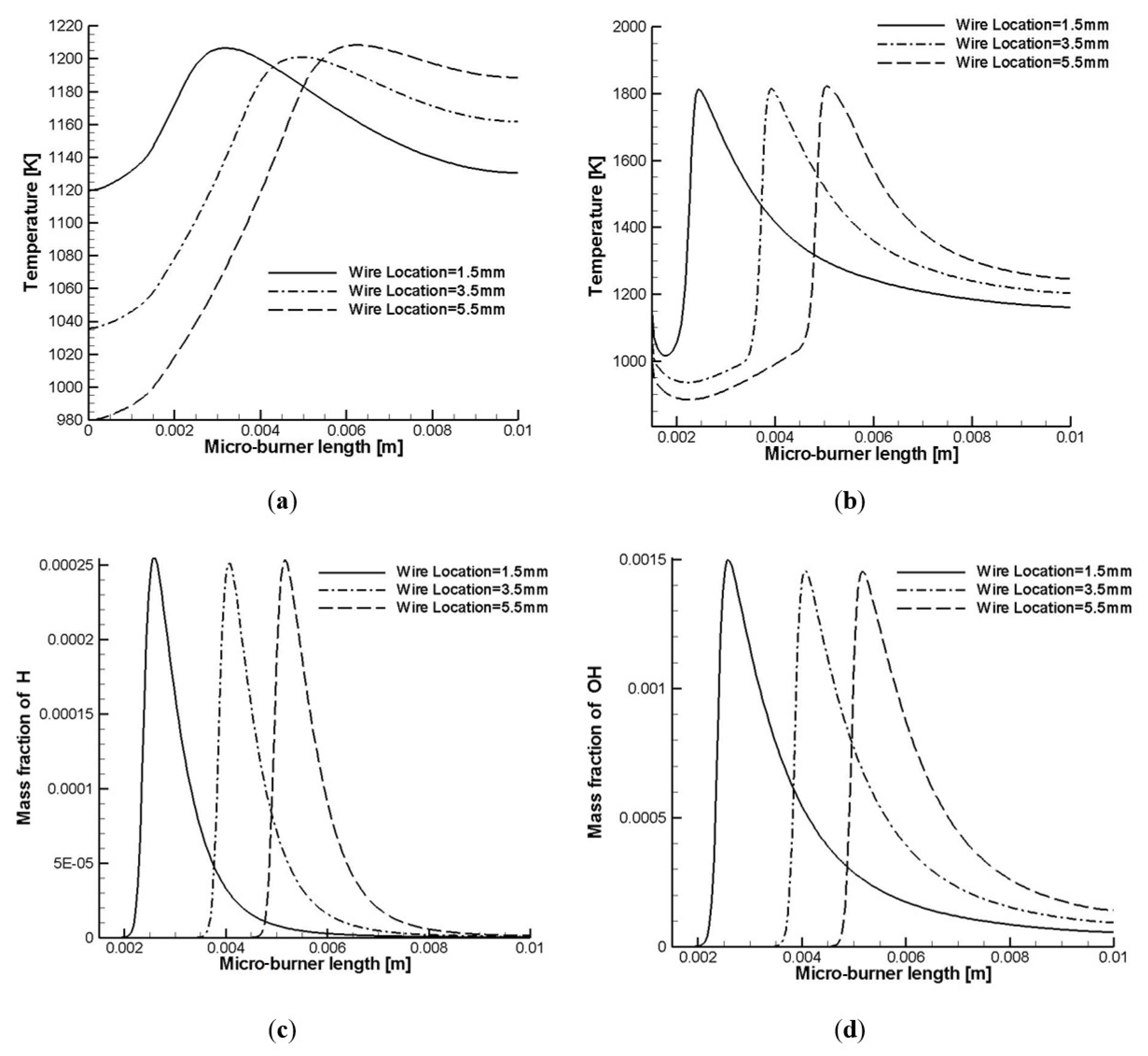
3.3. Effect of the Wire’s Location on Flame Characteristics

The effect of the axial location of the inserted wire on the flame characteristics is discussed in this section. Here, it should be noted that the wire’s diameter for all the studied cases in this section is 0.1 mm. As seen in Figure 8 and Figure 9, the location of the inserted wire has a significant effect on the flame presence range in the micro-burner/combustor. As seen in Figure 9b, there is a linear relationship between the wire and the flame locations in the micro-burner. In this regard, the flame location moves towards the outlet by gradually pulling the inserted wire tip from the backward-facing step towards the outlet, so that the wire’s effect would be disappeared beyond the axial location of 4.5 mm from the inlet (Figure 8). As seen in Figure 9a, and like the effect of the wire’s diameter on the flame establishment in the micro-burner, the hot tip of the inserted wire promotes the ignition process (production of methyl radical) in the burner/combustor with the wire’s axial position in the micro-burner and its temperature. Hence, it is seen in Figure 9a that the higher wire’s tip temperature leads to the higher methyl-mass fraction level on the inserted wire.
Furthermore, Figure 10a demonstrates that the axial position of the inserted wire has a significant effect on temperature distribution on the micro-burner’s wall. In this regard, the closer location of the inserted wire to the backward-facing step leads to a more uniform temperature distribution, with a significantly higher average temperature level on the outer surface of the micro-burner. As seen in Figure 10a, locating the wire 1.5 mm away from the step leads to a temperature distribution level of 1155 ± 44.44 K (the mean value ± the standard deviation) along the outer wall, whereas this value worsens to 1122 ± 80.30 K and 1125 ± 125.8 K, when we increase the distance to 3.5 mm and 5.5 mm away from the step, respectively. This means that moving the flame location towards the backward-facing step (Figure 10b) provides enough room for heating up, and then for a more uniform temperature distribution on the wall using the post-flame high-temperature gases. This room for the heat transfer from the post-flame hot gases is limited further by moving the wire away from the step, and consequently moving the flame front towards the outlet. This effect is very crucial when the micro-burner would be applied for micro-TPV or micro-TEG applications, in which a more uniform and higher temperature distribution on the outer surface of the micro-burner/combustor is desired. However, it is seen in Figure 10b that the wire’s axial location has not any specific effect on the temperature distribution on the auxiliary axis of r = 0.3 mm, unless it moves the flame zone towards the backward-facing step by intruding the wire further into the micro-burner. Moreover, Figure 10c,d confirms that a further intrusion of the wire into the burner/combustor promotes chemical reactions, and the production of some critical species such as the H-atom and hydroxyl radical in the combustion domain, in general, and on the inner surface of the micro-burner’s wall. This is due to indirect heat recirculation from the post-flame to pre-flame zones in the micro-burner/combustor through the wire. In this regard, it could be maintained that promoting these critical species near the inner surface of the burner’s wall may increase the flame presence range against a massive heat-loss rate from the outer wall of the micro-burner/combustor. This may extend the flame presence range and then the combustion efficiency in the micro-burner/combustors.

4. Conclusions

The effects of an inserted wire on the combustion characteristics of premixed methane–air flames in a micro-burner/combustor were investigated numerically in terms of the wire’s diameter and its axial location in the micro-burner. The results showed that although the wire’s diameter had no significant effect on the flame location in the micro-burner, its axial location played a crucial role in the flame presence range in the micro-burner. In this regard, the flame location was changed linearly by the wire’s axial position in the micro-burner. Moreover, performing the chemical flux analyses demonstrated that increasing the temperature of the pre-flame zone in the micro-burner significantly promoted fluxes of some crucial reactions such as CH4 + Ḣ → ĊH3 + H2; CH4 + ȮH → ĊH3 + H2O; ĊH3 + O2 → CH3Ȯ + Ȯ; ĊH3 + Ȯ → CH2O + Ḣ which consequently led to the faster production of critical radicals species such as the hydrogen atom, hydroxyl, and methyl in the combustion zone in the micro-burner/combustor. Increasing the production of the species facilitated the ignition process and the flame stabilization in the micro-burner/combustor. Moreover, increasing the production of the species facilitated the ignition process and the flame stabilization in the micro-burner/combustor. In addition, the results of the study demonstrated that the temperature distribution on the outer surface of the burner was more influenced by the wire’s axial location than the wire’s diameter. Therefore, the closer the wire to the backward-facing step, the more elevated the temperature distribution level and uniformity on the micro-burner’s wall. This effect may be an influential parameter in designing new micro-burners/combustors, including micro-TPVs or micro-TEGs.

Author Contributions

Conceptualization, M.B. and J.Z.; methodology, M.B. and J.Z.; software, J.Z.; validation, J.Z.; formal analysis, J.Z.; investigation, M.B. and J.Z.; resources, J.Z.; writing—original draft preparation, M.B.; writing—review and editing, S.T.; visualization, J.Z.; supervision, S.T.; project administration, M.B. and S.T. All authors have read and agreed to the published version of the manuscript.

Funding

This research received no external funding.

Institutional Review Board Statement

Not applicable.

Informed Consent Statement

Not applicable.

Data Availability Statement

Not applicable.

Conflicts of Interest

The authors declare no conflict of interest.

References

  1. Chou, S.K.; Yang, W.M.; Chua, K.J. Development of micro power generators—A review. Appl. Energy 2011, 88, 1–16. [Google Scholar] [CrossRef]
  2. Aravind, B.; Khandelwal, B.; Ramakrishna, P.A.; Kumar, S. Towards the development of a high power density, high efficiency, micropower generator. Appl. Energy 2020, 261, 114386. [Google Scholar] [CrossRef]
  3. Importance of Methane. 2021. Available online: https://www.epa.gov/ (accessed on 20 December 2021).
  4. Esrafilzadeh, D.; Zavabeti, A.; Jalili, R.; Atkin, P.; Choi, J.; Carey, B.J.; Brkljaca, R.; O’Mullane, A.P.; Dickey, M.D.; Officer, D.L.; et al. Room temperature CO2 reduction to solid carbon species on liquid metals featuring atomically thin ceria interfaces. Nat. Commun. 2019, 10, 865. [Google Scholar] [CrossRef] [PubMed]
  5. Yang, W.M.; Chou, S.K.; Shu, C.; Li, Z.W.; Xue, H. Combustion in micro-cylindrical combustors with and without a backward facing step. Appl. Therm. Eng. 2002, 22, 1777–1787. [Google Scholar] [CrossRef]
  6. Chen, G.; Chao, Y.; Chen, C. Enhancement of hydrogen reaction in a micro-channel by catalyst segmentation. Int. J. Hydrogen Energy 2008, 33, 2586–2595. [Google Scholar] [CrossRef]
  7. Ronney, P. Analysis of non-adiabatic heat-recirculating combustors. Combust. Flame 2003, 135, 421–439. [Google Scholar] [CrossRef]
  8. Baigmohammadi, M.; Sarrafan-Sadeghi, S.; Tabejamaat, S.; Zarvandi, J. Numerical study of the effects of wire insertion on CH4 (methane)/Air pre-mixed flame in a micro combustor. Energy 2013, 54, 271–284. [Google Scholar] [CrossRef]
  9. Baigmohammadi, M.; Tabejamaat, S. Experimental study on the effect of external thermal pattern on the dynamics of methane-oxygen and methane-oxygen carbon dioxide premixed flames in non-adiabatic meso-scale reactors. Int. J. Therm. Sci. 2019, 137, 242–252. [Google Scholar] [CrossRef]
  10. Baigmohammadi, M.; Tabejamaat, S.; Yeganeh, M. Experimental study of methane-oxygen premixed flame characteristics in non-adiabatic micro-reactors. Chem. Eng. Process. 2019, 142, 107590. [Google Scholar] [CrossRef]
  11. Baigmohammadi, M.; Tabejamaat, S.; Kashir, B. A numerical study on the effects of hydrogen addition levels, wall thermal conductivity and inlet velocity on methane/air pre-mixed flame in a micro reactor. Energy Equip. Syst. 2014, 2, 103–119. [Google Scholar]
  12. Baigmohammadi, M.; Roussel, O.; Dion, C.M. A Numerical Study of Lean Propane-Air Flame Acceleration at the Early Stages of Burning in Cold and Hot Isothermal Walled Small-Size Tubes. Flow Turbul. Combust. 2019, 104, 179–207. [Google Scholar] [CrossRef] [Green Version]
  13. Alipoor, A.; Mazaheri, K. Studying the repetitive extinction-ignition dynamics for lean premixed hydrogen-air combustion in a heated microchannel. Energy 2014, 73, 367–379. [Google Scholar] [CrossRef]
  14. Ju, Y.; Xu, B. Effects of channel width and Lewis number on the multiple flame regimes and propagation limits in meso-scale. Combust. Sci. Technol. 2006, 178, 1723–1753. [Google Scholar] [CrossRef]
  15. Senchenko, S.; Bychkov, V.; Liberman, M. Stability limits of curved stationary flames in cylindrical tubes. Combust. Sci. Technol. 2001, 166, 109–130. [Google Scholar] [CrossRef]
  16. Tsai, C.H. The asymmetric behavior of steady laminar flame propagation in ducts. Combust. Sci. Technol. 2008, 180, 533–545. [Google Scholar] [CrossRef]
  17. Jackson, T.B.; Virkar, A.V.; More, K.L.; Dinwiddie, R.B.; Cutler, R.A. High-Thermal-Conductivity Aluminum Nitride Ceramics: The Effect of Thermodynamic, Kinetic, and Microstructural Factors. J. Am. Ceram. Soc. 2005, 80, 1421–1435. [Google Scholar] [CrossRef]
  18. Rahman, M.M.; Miettinen, A.; Siikonen, T. Modified Simple Formulation on a Collocated Grid with an Assessment of the Simplified Quick Scheme. Numer. Heat Transf. Part B Fundam. 1996, 30, 291–314. [Google Scholar] [CrossRef]
  19. Li, J.; Chou, S.K.; Li, Z.W.; Yang, W.M. Characterization of wall temperature and radiation power through cylindrical dump micro-combustors. Combust. Flame 2009, 156, 1587–1593. [Google Scholar] [CrossRef]
  20. Martinez, S.; Baigmohammadi, M.; Patel, V.; Panigrahy, S.; Sahu, A.B.; Nagaraja, S.; Ramalingam, A.; Heufer, K.A.; Pekalski, A.; Curran, H.J. A comprehensive experimental and modeling study of the ignition delay time characteristics of ternary and quaternary blends of methane, ethane, ethylene, and propane over a wide range of temperature, pressure, equivalence ratio, and dilution. Combust. Flame 2021, 234, 111626. [Google Scholar] [CrossRef]
  21. Goodwin, D.G.; Speth, R.L.; Moffat, H.K.; Weber, B.W. Cantera: An Object-Oriented Software Toolkit for Chemical Kinetics, Thermodynamics, and Transport Processes; Version 2.5.1; 2021; Available online: https://www.cantera.org (accessed on 20 December 2021). [CrossRef]
  22. Smooke, M.; Giovangigli, V. Formulation of Test Premixed and Nonpremixed Test Problems, Reduced Kinetic Mechanisms and Asymptotic Approximations for Methane-Air Flames; Springer: Berlin/Heidelberg, Germany, 1991; Volume 384. [Google Scholar]
  23. Nagaraja, S.S.; Sahu, A.B.; Panigrahy, S.; Curran, H.J. A fundamental study on the pyrolysis of hydrocarbons. Combust. Flame 2021, 233, 111579. [Google Scholar] [CrossRef]
Figure 1. The geometry of the studied micro-burner (dimensions in “mm”) [8].
Energies 15 00093 g001
Figure 2. The studied computational mesh; temperature distribution on the auxiliary axis of r = 0.3 mm.
Energies 15 00093 g002
Figure 3. Contours of OH mass fraction show how the flame location in the micro-burner/combustor is affected by variations in the wire diameter.
Energies 15 00093 g003
Figure 4. (a) The effect of wire diameter on temperature and methyl radical distribution on the outer surface of the inserted wire; (b) the flame location versus diameter of the inserted wire.
Energies 15 00093 g004
Figure 5. Flux analysis of methane consumption (20%) at three different temperatures corresponding to the axial distance where CH3 mass fraction starts to rise: (Blue) 1330 K (Dwire: 0.1 mm); (Red) 1420 K (Dwire: 0.15 mm); (Black) 1430 K (Dwire: 0.25 mm); “M” refers to a third body reaction.
Energies 15 00093 g005
Figure 6. (a) Distribution of the H mass fraction on the inner wall for different diameters of the inserted wire; (b) distribution of the OH mass fraction on the inner wall for different diameters of the inserted wire; (c) distribution of H mass fraction on the axial line defined at r = 0.3 mm for different diameters of the inserted wire; (d) distribution of OH mass fraction on the axial line defined at r = 0.3 mm for different diameters of the inserted wire.
Energies 15 00093 g006
Figure 7. (a) Distribution of temperature on the outer surface of the micro-burner for different diameters of the inserted wire; (b) distribution of temperature on the axial line defined at r = 0.3 mm for different diameters of the inserted wire.
Energies 15 00093 g007
Figure 8. Contours of OH mass fraction in the micro-burner for different locations of the inserted wire.
Energies 15 00093 g008
Figure 9. (a) The effect of wire location on temperature and methyl radical distribution on the outer surface of the wire; (b) The flame location versus the location of the inserted wire.
Energies 15 00093 g009
Figure 10. (a) Distribution of temperature on the outer surface of the micro-burner for different locations of the inserted wire; (b) distribution of temperature on the axial line defined at r = 0.3 mm for different locations of the inserted wire; (c) distribution of H mass fraction on the inner wall for different locations of the inserted wire; (d) distribution of OH mass fraction on the inner wall for different locations of the inserted wire.
Energies 15 00093 g010
Table 1. Some of the applied values in the study.
Inlet velocity (Vin)2.8 m/s
Wire’s thermal conductivity (Kwire)170 W/m·K
Wall’s thermal conductivity (Kw)20 W/m·K
External heat transfer coefficient (hout)5 W/m2·K
External emissivity coefficient (e)0.2
Equivalence ratio (φ)0.9
Publisher’s Note: MDPI stays neutral with regard to jurisdictional claims in published maps and institutional affiliations.

