Abstract
The seal is designed to reduce leakage and improve the efficiency of gas turbine machines, and is an important technology that needs to be studied in gas turbine design. A series of seals were proposed to try to achieve this goal. However, due to the complex fluid dynamic performance of the seal-rotor system, the seal structure can obtain both the best leakage performance and best rotordynamic performance. This paper presents a detailed flow analysis of the hole diaphragm labyrinth seal (HDLS) at several whirl frequencies and several rotation speeds. The pressure drop, velocity, turbulence kinetic energy and leakage performance of the HDLS were discussed by simulations. An interesting exponential–type relationship between rotation speeds and leakage flow at different whirl frequencies was observed by curve fitting technology. A reverse flow rate was proposed to describe such an unusual phenomenon. Such a relationship can be used to further establish the leakage model of the HDLS and other similar seals.
1. Introduction
Gas turbines and steam turbines, which can be both called “pearls on the crown of the manufacturing industry,” are two of the most complex machines in the current industry. A traditional gas turbine is usually composed of a compressor, combustion chamber and turbine parts. Due to the fact that the working materials are usually gas air and steam, which can both be treated as gas, the leakage performance in the whole system should be considered carefully in the design phase. Different seal structures were proposed to reduce gas leakage to enhance the utilization rate of gas. One of these various seals is the labyrinth seal (LS).
According to the positions of seal blades and whether they have stages, the LS can be classified as a vane seal, gland seal, shaft seal, vane stage seal, interlocking labyrinth seal, and so on. Jiang [1] compared the rotordynamic performance of the vane seal, gland seal and shaft seal by both experimental and numerical results. The results showed that the influence of steam forcing on rotordynamic coefficients was dominated by the shaft seal. Andrés [2] studied the influence of the leakage on several preswirl pressures, inlet pressures and shaft speeds. Two flow loss coefficients used in the bulk-flow model [3] for the interlocking labyrinth seal (ILS) with clearances of 0.3 mm and 0.13 mm were proposed to predict the leakage performance more accurately, which can be used in predicting such seals. The LS added to the rotor system cannot only bring lower leakage but also cause some new problems to appear. The rotor is affected by an additional airflow excitation force. Childs [4] and Alford [5] improved and perfected the rotordynamic coefficients of seals considered in rotor systems in the last century. Many studies have appeared to consider both leakage and rotordynamic performance individually. Wang [6] proposed a mathematical model that describes the relationship between the leakage and rotordynamic coefficients. A series of tilting conditions of the rotor was considered by both Si [7] and Zhang [8] to study the rotordynamic performance. Zhang [9] and Sun [10] focused on improving rotordynamic stability using preswirl inlet conditions.
Meanwhile, a labyrinth seal can be used not only in the gas turbine field but also in the pumps. Rong [11] used a traditional labyrinth seal and screw blades for reference and proposed a labyrinth screw pump, which can moderately reduce the leakage and energy loss of the pump with optimized parameters. In brief, the labyrinth seal is designed to reduce the leakage in rotating machines by the contraction throttling effect of the seal blades and by the vortex dissipation of the cavities between every two blades. For the boundary conditions in the industrial application of LS, always using the pressure inlet and outlet conditions, the velocity, energy, and pressure analysis of the flow domain becomes an important thing during LS research. The streamline containing vortices is also a clear method to describe how the LS works. Zeng [12] focused on the tip-leakage flow of the turbine. The relationship between suction side squealer rim width and leakage performance was analyzed in detail by flow analysis. Moreover, entropy and friction analysis were both considered in the study.
Furthermore, the damping seal is one of the typical seal structures used in gas turbines. Zhang [13] focused on the hole pattern damping seal (HPDS), one of the typical damping seal structures, and studied the leakage reduction with different angles with the axis, which showed a 25% leakage reduction compared to that of the straight HPDS. The streamlined study showed that the windward inclined HPDS could cause at least one more vortex in each hole pattern, which leads to extra energy dissipation. Moreover, different diameter conditions were proposed to adapt to different clearance conditions. Another kind of damping seal named the honeycomb seal has been discussed by numerous scholars. Both Zaniewski [14], Szymański [15] and Lu [16] studied honeycomb–labyrinth seals (HLSs). Zaniewski compared the leakage flow rates of the HLS and traditional LS. An advantage in the leakage flow rate of the HLS was found. However, the gland friction losses increased at the same time, which caused extra energy consumption in the system. The schlieren technique was used by Szymański to study the sophisticated flow form of the HLS. Lu focused on the damage caused by the friction between honeycomb sidewalls and labyrinth seal fins, which can also be found in Chen’s [17] research.
Recently, some new kinds of seal structures, whether combined with several traditional seals or modifications designed on parts of whole structures, have become increasingly popular. Li [18] combined the LS and the nozzle structure to set up the combined seal structure (CSS). The leakage performance of the CSS was reduced to almost 40% compared to that of the LS. Moreover, the leakage rate decreased with the increasing inlet flow. Similar ideas can be found in Zhang [19], who showed that helical-labyrinth seals with brushes upstream and downstream were proposed to obtain an excellent sealing performance. Meanwhile, a new type of scallop seal with sickle grooves was proposed by Zahorulko to study its leakage performance [20,21]. Campagnoli [22] chose a combination of the honeycomb structure with diamond sidewalls and a stepped honeycomb labyrinth seal. Wasilczuk [23] designed a new type of labyrinth blade, which has an extra tube in the blade body that can cause a high-velocity jet in the clearance. The new blade, using the passive flow control technique, did show the advantage of reducing leakage without extra structures.
In this paper, a type of hole diaphragm labyrinth seal (HDLS) based on a traditional LS was presented. Simulations of an HDLS at different whirl frequencies and rotation speeds were calculated. Subsequently, pressure, velocity, turbulence kinetic energy, and leakage values on several working panels and lines were selected to draw a series of figures. Moreover, an interesting relationship between working conditions and leakage of an HDLS was analyzed by curve fitting technology. The physical characteristics of the influence of working conditions on the leakage of an HDLS were discussed in detail. The studies in this paper have bright prospects for establishing a leakage model for the new type of labyrinth seal.
2. Materials and Methods
The traditional LS system was built by a rotor and a shell with a series of blades. The traditional LS sectional drawing is shown in Figure 1, and the design parameters are shown in Table 1.
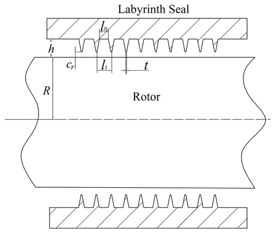
Figure 1.
Sectional drawing of traditional LS structure.

Table 1.
Design parameters of LS in Ref [9].
The hole diaphragm labyrinth seal (HDLS) was designed based on a traditional LS. The difference between the LS and HDLS is adding four groups of diaphragms with a hole through each diaphragm’s center to divide each level cavity into four cavities, which could introduce additional wall impedance. Meanwhile, the hole in each diaphragm can balance the circumferential pressure. The schematic diagram and control parameters of HDLS are shown in Figure 2.
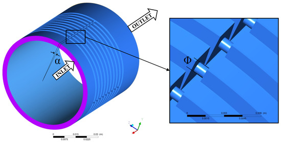
Figure 2.
Schematic diagram of the hole diaphragm labyrinth seal (HDLS).
ANSYS Fluent was used in this paper to establish the simulations. To describe the flow field of HDLS in detail, several calculation lines and panels were set up, as shown in Figure 3. Subsequently, the ICEM meshing of the flow domain, which contains 8.93 million elements, was built, as shown in Figure 4. The parameters used in the simulations are shown in Table 2.
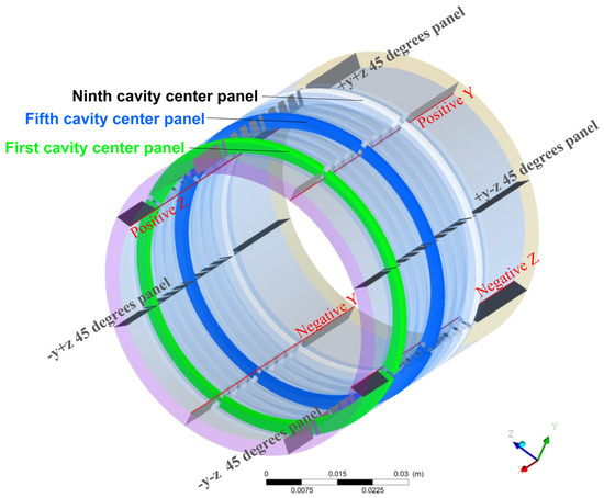
Figure 3.
Analysis panels and lines setting.

Figure 4.
Meshing diagram of +y+z 45 degrees panel.

Table 2.
Simulation values of HDLS.
The whirl radius considered in this paper was in the positive direction of the y-axis, as shown in Figure 5a. The dynamic simulation of the whirl seal-rotor system requires a dynamic mesh, which requires considerable computational power and takes a long time. A quasi-steady-state model [9], shown in Figure 5b, was used to transfer the dynamic mesh to the fixed mesh, which is much easier to calculate.
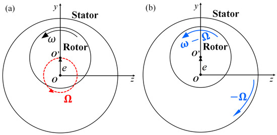
Figure 5.
Schematic diagram of the quasi-steady-state model.
Furthermore, the simulation method was validated by comparison with the experimental results of traditional LS studied in reference [9]. The comparison curves were drawn in Figure 6. The maximum error between the simulation methods used in this paper is lower than 6%. Moreover, the minimum error ratio reaches 0.43% at a clearance of 0.02 mm. The simulation method used in this paper can be considered acceptable by validation. Subsequently, the same boundary conditions and the control parameters were used to study the HDLS.
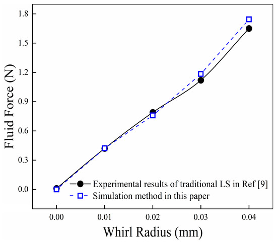
Figure 6.
Simulation reliability validation.
3. Results and Discussions
3.1. Validation of Grid Independence
Due to the calculated fluid mechanics (CFD) method being used in the simulations, grid independence validation was necessary. It uses the parameters listed in Table 2 to establish four groups of meshes. The leakage performance and corresponding calculation time of 1.45 million, 5.66 million, 8.93 million, and 14.5 million element meshes can be drawn as Figure 7. Figure 7 clearly shows that the leakage difference between the 8.93 million elements and 14.5 million elements mesh is lower than 0.15%, while the time cost of 14.5 million has almost twice the difference than that of the 8.93 million. Therefore, 8.93 million elements mesh was picked as it is astringent enough on leakage performance and has an acceptable time cost.
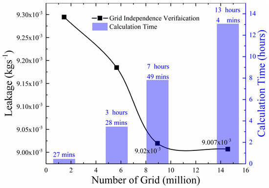
Figure 7.
Leakage performance of different elements meshing.
3.2. Pressure
Figure 8 shows that the pressure of different whirl frequencies in the positive y-direction basically changes with the same trend. Due to the throttling effect of each blade, the pressure curves present a step-like form. The partially enlarged view shown on the right of Figure 8 shows that the pressure in cavity 1 has almost no change. The pressure values, which are under the 150 Hz whirl frequency condition, are slightly lower than those of the 200 Hz, 250 Hz, and 300 Hz whirl frequencies at the position near the beginning of cavity 1. However, the pressure keeps reducing slightly in the middle rear part of cavity 1 with whirl frequencies rising.
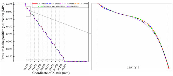
Figure 8.
Pressure in the positive y-direction at different whirl frequencies ( = 5000 rpm).
The comparison between different positions under the 300 Hz whirl frequency condition is shown in Figure 9. The same trend, which shows a step-like form, can be found in different positions. The difference between different positions shows a slight change compared to that of different whirl frequencies. The curve of the negative y position is always lower than that of the positive y position because the whirl radius of the quasi-steady-state model in the calculation is positive y, which squeezes air into the negative y-direction. Meanwhile, the pressure distributions in both the positive and negative z-directions are completely the same, but different from those in the y-axis directions.
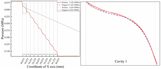
Figure 9.
Pressure comparison of different circumferential directions ( = 300 Hz).
Figure 10 shows the pressure drops in the positive y-direction with cavity boundary coordinates at the points where the calculation starts and ends. It is obvious that the pressure drops in the different cavity positions are not the same. Lower values can be obtained in the first and eighth cavities. However, the larger values are in the fifth and ninth cavities.
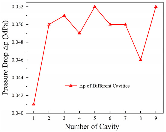
Figure 10.
Pressure drop in the positive y-direction.
3.3. Velocity
The velocity curves in different directions and different whirl frequencies are shown in Figure 11.
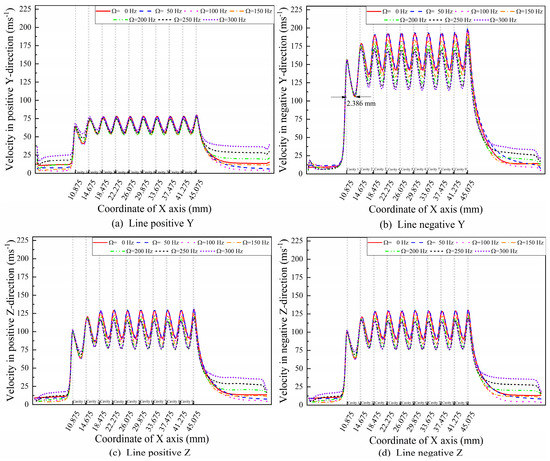
Figure 11.
Velocity curves in different directions with different whirl frequencies ( = 5000 rpm).
Since the displacement of the rotor surface is always in the positive y-direction, by using the quasi-steady-state model shown in Figure 5, the velocity values in the positive z- and negative z-directions show the same changeable trend. However, the velocity values in the positive y-direction are lower than those in the negative y-direction. Some whirl frequency dependence in the y-direction shows a considerable difference between the positive y- and negative y-directions. In particular, the velocities in the first and second cavities decrease first and then increase with the whirl frequency rising all the time in the positive y-direction, while the velocity values in whole cavities in the negative y-direction keep decreasing with increasing whirl frequency. Meanwhile, the marked distance in Figure 11b, which can also be found in other directions, shows the whole process of the working medium. The air particles are accelerated to reach their maximum velocity values by the throttling effect at the end of the blade positions and then start to slow down by eddy dissipation to reach their minimum velocities at 2.386 mm behind each blade.
In addition, the differences in the circumferential direction velocity in the first, fifth, and ninth cavities are shown in Figure 12 and Figure 13, where the u, v and w directions correspond to the x, y and z directions. The hole domains marked by rectangular boxes in Figure 12a and Figure 13a have a series of separated isopleths. In other words, the gradient of velocity on both sides of the hole domains can cause medium particle friction of the HDLS. Hence, extra energy dissipation appears in the HDLS, which cannot be found in the traditional labyrinth seal. However, such a phenomenon is not completely observed in the w-direction, shown by the black dashed rectangular box in Figure 12b, which can be explained by the whirl radius always in the y-direction in the quasi-steady-state model used in this paper. The whirl frequency dependence of velocity in the v-direction is observed by comparing Figure 12a and Figure 13a, which shows that the velocity gradient in the v-direction in hole domains increases with increasing whirl frequency. Such a rule can be observed by comparing the velocity gradient in the w-direction shown in Figure 12b and Figure 13b. Moreover, the offset of the isoline in different cavities observed in Figure 12a shows the influence of the whirl movement of the rotor during the rotor rotation itself.
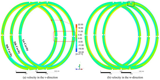
Figure 12.
Circumferential direction velocity isopleth diagram in the first, fifth, and ninth cavities ( = 5000 rpm, = 50 Hz).
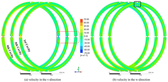
Figure 13.
Circumferential direction velocity isopleth diagram in the first, fifth, and ninth cavities ( = 5000 rpm, = 300 Hz).
3.4. Turbulence Kinetic Energy
To further understand the airflow in the HDLS, a series of analyses under 5000 rpm rotation speeds was performed below. The streamlines starting from eight working panels can be drawn as Figure 14.
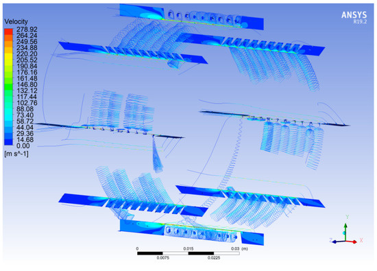
Figure 14.
Streamlines form eight panels of HDLS ( = 5000 rpm, = 50 Hz).
Figure 14 shows that vortices appear after fluid passes through each stage blade. The streamlines drawn from the positive z and negative z panels show that the fluid does pass through the holes. Due to the quasi-steady-state model, the rotation speed of the rotor is − = 2000 rpm in the negative x-direction, and the rotation speed of the stator is − = 3000 rpm in the positive x-direction, which makes the direction of fluid flow in the first cavity show a different trend in the positive z-direction. The vortices in different cavities can be observed clearly in Figure 15. Both Figure 15a,b show the surface streamline on two typical panels of the HDLS. The streamlines in cavities 1, 5, and 7 are slightly sparser than those of other cavities on the +y-z 45 degree panel. However, the different phenomenon is that sparser areas appear in the first, eighth and ninth holes on the positive y panel. Compared with Figure 10, the lower pressure drop in the first cavity can be explained by the lower vortex friction. Moreover, a diffuse vortex appears behind the tenth blade. For the tailed cavities that show different depths, the streamlines of the vortex in Figure 15a are slightly more concentrated than those in Figure 15b. The distance of jet flow from the tenth blade on the positive y panel is longer than that on the +y-z 45 degree panel at the same time.
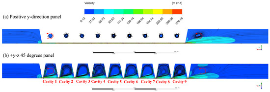
Figure 15.
Surface streamline and velocity contour of HDLS ( = 5000 rpm, = 50 Hz).
Furthermore, the turbulence kinetic energy contours of the HDLS on both the +y+z 45 degree and -y-z 45 degree panels are drawn in Figure 16. The clearance on the +y+z 45 degrees panel shown in Figure 16a is slightly larger than 0.19 mm, which is slightly lower than 0.21 mm on the -y-z 45 degrees panel. The different velocity gradients in the center of the cavity can be found as the red sections show in Figure 16. Meanwhile, the last jet flow behind the tenth blade on the +y+z 45 degree panel is slightly shorter than that on the -y-z 45 degree panel.

Figure 16.
Turbulence kinetic energy contour of HDLS ( = 5000 rpm, = 50 Hz).
The turbulence kinetic energy curves can be drawn as in Figure 17, by extracting values on the line of the positive y-direction with different whirl frequencies considered at 5000 rpm rotation speed. It is obviously found that the turbulence kinetic energy in cavities 2 to 9 presents a whirl frequency dependence much more than that of the domain behind the tenth blade, and a trend cannot be found easily in the first cavity. The turbulence kinetic energy of different cavities keeps rising with increasing whirl frequencies. In addition, the turbulence kinetic energy of different positions is considered in Figure 18. It is clearly shown in both the 0 Hz and 300 Hz working conditions that turbulence kinetic energy in the positive y-direction is lower than that in the negative y-direction, which is caused by the whirling rotor squeezing the positive y domain and making the negative y domain a much better working medium to participate in vortex generation. Meanwhile, the curves in Figure 18 show that the maximum turbulence kinetic energy values have a 0.842 mm distance behind each stage blade in each cavity, which can also be observed in Figure 16. In addition, the trends in the positive z- and negative z-directions show different relationships at different whirl frequencies. The turbulence kinetic energy in both the positive z- and negative z-directions is in the middle of that in the positive y- and negative y-directions at a 0 Hz whirl frequency. However, the turbulence kinetic energy in the positive z- and negative z-directions is larger than that in the positive y- and negative y-directions at a 300 Hz whirl frequency. Furthermore, the same change trend of turbulence kinetic energy in each cavity, which actually affects the leakage performance of the seal rotor system, can also be found in Tang’s research [24].
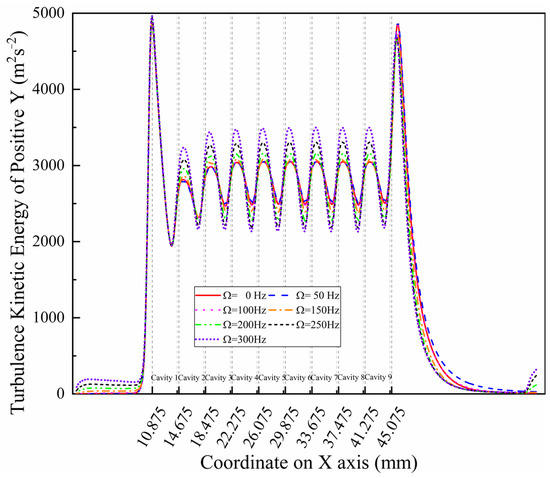
Figure 17.
Turbulence kinetic energy in the positive y-direction ( = 5000 rpm).
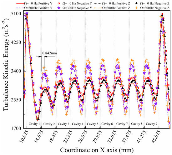
Figure 18.
Turbulence kinetic energy with different positions and whirl frequencies ( = 5000 rpm).
Another parameter that can demonstrate the fluid characteristics is eddy viscosity. The contour figure on different panels is shown in Figure 19. The eddy viscosity contour figure reflects the stress-rising areas, which are always observed before the tips of the blades. Figure 19c also shows that the eddy viscosity in both cavity 1 and cavity 9 is slightly lower than that in the other panels. The possible reason is that even if the whirl radius is in the direct positive y-direction, the circumferential speed between the rotor and the HDLS is still not the same because of the whirl eddy motion.
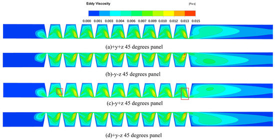
Figure 19.
Eddy viscosity of HDLS ( = 5000 rpm, = 50 Hz).
3.5. Leakage Performance
The purpose of the seal is to reduce the leakage flow, which can improve both the work efficiency of the turbine and compressor. Discussions on the leakage performance of the HDLS are necessary. Figure 20 shows the leakage comparison between the HDLS and traditional LS at a 50 Hz whirl frequency. The results show that the hole diaphragm labyrinth seal presented in this paper obtains a 3.53% reduction in leakage performance, compared to that of the traditional LS, which can be described by the extra eddy dissipation effect in circumferential directions.
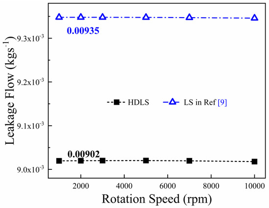
Figure 20.
Comparison of leakage performance at a 50 Hz whirl frequency between HDLS and traditional LS in Ref [9].
The leakage performance of the HDLS at different whirl frequencies is shown in Figure 21.
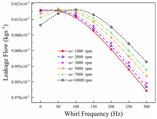
Figure 21.
Leakage performance of HDLS at different whirl frequencies.
It is obviously found that the relationship between the whirl frequency and leakage basically follows a quadratic form. Especially when considering rotation speeds larger than 2000 rpm, the leakage flow of the HDLS increases with increasing whirl frequency. Then, a maximum value is obtained at the smaller whirl frequencies, before the leakage flow keeps decreasing with a further increase in whirl frequency. Meanwhile, the peaks of the curves drift to the right as the rotation speed rises. Furthermore, a nonlinear curve fitting at different whirl frequencies, shown in Figure 22, is used to describe the relationship between the rotation speed and leakage flow of the HDLS.
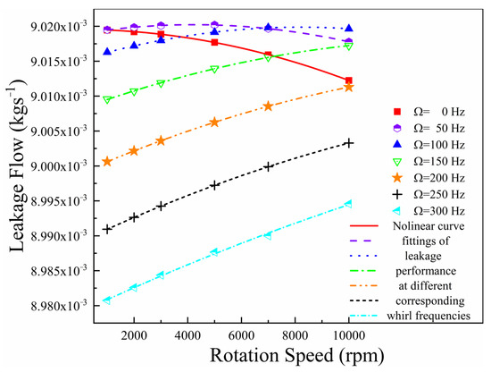
Figure 22.
Nonlinear curve fittings of leakage flow at different whirl frequencies.
Figure 22 shows the leakage performance of the HDLS at different rotation speeds. It is obvious that the leakage decreases over time as the rotation speed increases at the 0 Hz whirl frequency, which conforms to the existing research on annular seals. The leakage curve appears to increase first at a 50 Hz whirl frequency before a 4000 rpm rotation speed and then decreases with the increasing rotation speed, which is also similar to the existing results. A similar phenomenon can be observed at a whirl frequency of 100 Hz. The experimental results of Childs [25] show that leakage decreases with increasing rotation speeds which are higher than 10,200 rpm. However, the curves at higher whirl frequencies, which means higher than 50 Hz, do not follow such rules. The velocity on the rotor surface can be described by , which is presented in Figure 5. The velocity on the rotor surface encounters one reverse in the circumferential direction at different whirl frequencies when the whirl frequency is lower than 200 Hz. For example, obtained a value of 100 rad/s when the seal surface and working medium obtained a value of rad/s at a 50 Hz whirl frequency and 4000 rpm rotation speed. The values of will be 0 rad/s and −100 rad/s when working at 3000 rpm and 2000 rpm rotation speeds at a 50 Hz whirl frequency. The maximum value of leakage was also observed at 4000 rpm, in which the velocity on the rotor surface turned to another direction of the working medium at a 50 Hz whirl frequency. A similar phenomenon can be found at 7000 rpm rotation speed and 100 Hz whirl frequency, in which the leakage reaches its maximum when is 100 rad/s. It can be inferred that the small reverse flow rate between the rotor surface and the working medium at the change moment will reduce the sealing performance by reducing the continuity of particle velocity on the rotor surface. A comparison between Figure 12a,b, which describes the circumferential drift of the velocity isopleth, can only be observed easily at 50 Hz instead of at 300 Hz, and can also validate this phenomenon.
In other words, leakage performance cannot be described only by rotation speed dependence but also needs to consider the influence of whirl frequency. It can also be found that the maximum of the leakage curves drift to a higher rotation speed with increasing whirl frequency. This phenomenon is similar to the quadratic equation with a negative constant on the quadratic term. Subsequently, the mathematical relation between rotation speed (Hz) and leakage (kg/s) can be written as follows:
where ; and , , and are three constant terms which have different values in different whirl frequency conditions. Meanwhile, , a parameter that can evaluate the goodness of curve fitting [26], reaches . Moreover, the different groups of constant terms with their standard deviation and the corresponding are listed in Table 3.

Table 3.
Constant terms and values at different whirl frequencies.
The goodness of fit on different whirl frequencies is very close to the value that shows the best situation of curve fitting. Equation (1) shows the internal exponential connection between the rotor rotation frequency and leakage flow of the HDLS, which provides a new idea for leakage studies of seal structures.
4. Conclusions
A series of simulations were completed to understand further how the new structure, named a hole diaphragm labyrinth seal (HDLS), is proposed in this paper. The analysis focused on pressure, velocity, turbulence kinetic energy, and leakage performance. Some interesting phenomena were observed:
- The pressure drop in different cavities of the HDLS does not follow some specific rules, while the velocity values in each cavity show some peculiar phenomenon of the HDLS.
- The velocity values in different directions showed some whirl frequency dependence performance. Meanwhile, the velocity analysis in different cavities showed an additional energy dissipation source due to the hole-diaphragm structures added in the traditional labyrinth seal. The study on turbulence kinetic energy confirmed this advantage of the HDLS.
- The physical characteristics of the whirl frequency influence on the leakage of the HDLS were discussed in detail. A reverse flow rate between the rotor surface and working medium was proposed to describe the unusual phenomenon that the leakage increases at higher whirl frequencies.
- An exponential-type relationship between rotation speeds and leakage flow at different whirl frequencies was observed by curve fit technology, which can be used to predict leakage performance studies of hole diaphragm labyrinth seals, and provide an exciting direction for seal-rotor system studies.
Author Contributions
Conceptualization, X.Z. and Y.J.; methodology, X.Z.; software, X.Z.; validation, X.Z., Y.J. and X.Q.; formal analysis, X.Z.; investigation, Z.Z.; resources, X.Q.; data curation, G.H.; writing—original draft preparation, X.Z.; writing—review and editing, X.Z.; visualization, G.H.; supervision, Y.J.; project administration, X.Q.; funding acquisition, Y.J. All authors have read and agreed to the published version of the manuscript.
Funding
This research was funded by the National Science and Technology Major Project (2017-ⅠV-0010-0047) and the National Natural Science Foundation of China (No. 12072089; No. 11972131).
Conflicts of Interest
The authors declare no conflict of interest. The funders had no role in the design of the study, in the collection, analyses, or interpretation of data, in the writing of the manuscript, or in the decision to publish the results.
References
- Jiang, P.N.; Wang, W.Z.; Liu, Y.Z.; Meng, G. Influence of steam leakage through vane, gland, and shaft seals on rotordynamics of high-pressure rotor of a 1000 MW ultra-supercritical steam turbine. Arch. Appl. Mech. 2012, 82, 177–189. [Google Scholar] [CrossRef]
- Andrés, L.S.; Yang, J.; Kawashita, R. On the Effect of Clearance on the Leakage and Cavity Pressures in an Interlocking Labyrinth Seal Operating With and Without Swirl Brakes: Experiments and Predictions. J. Eng. Gas Turbines Power 2021, 143, 031003. [Google Scholar] [CrossRef]
- Thorat, M.R.; Childs, D.W. Predicted Rotordynamic Behavior of a Labyrinth Seal as Rotor Surface Speed Approaches Mach 1. J. Eng. Gas Turbines Power-Trans. Asme 2010, 132, 112504. [Google Scholar] [CrossRef]
- Childs, D.W. Finite-Length Solutions for Rotordynamic Coefficients of Turbulent Annular Seals. J. Tribol. 1983, 105, 437–444. [Google Scholar] [CrossRef]
- Alford, S.J. Protection of Labyrinth Seals From Flexural Vibration. ASME J. Eng. Gass Turbines Power 1964, 86, 141–147. [Google Scholar] [CrossRef]
- Wang, W.Z.; Liu, Y.Z.; Chen, H.P.; Jiang, P.N. Computation of rotordynamic coefficients associated with leakage steam flow through labyrinth seal. Arch. Appl. Mech. 2007, 77, 587–597. [Google Scholar] [CrossRef]
- Si, H.; Cao, L.; Li, P.; Chen, D. Steam flow excited vibration and dynamic characteristics of seal in different rotor whirling motion. Tribol. Int. 2021, 160, 107029. [Google Scholar] [CrossRef]
- Zhang, W.; Wang, Y.; Gu, Q.; Yin, L.; Yang, J. Rotordynamic Performance of the Interlocking Labyrinth Seal With a Tilting Rotor. J. Eng. Gas Turbines Power 2021, 143, 011012. [Google Scholar] [CrossRef]
- Zhang, W.; Gu, Q.; Cao, H.; Wang, Y.; Yin, L. Improving the rotordynamic stability of short labyrinth seals using positive preswirl. J. Vibroeng. 2020, 22, 1295–1308. [Google Scholar] [CrossRef]
- Sun, D.; Wang, S.; Xiao, Z.H.; Meng, J.G.; Wang, X.J.; Zheng, T.S. Measurement versus predictions of rotordynamic coefficients of seal with swirl brakes. Mech. Mach. Theory 2015, 94, 188–199. [Google Scholar] [CrossRef]
- Rong, X.; Zhu, H.; Hu, B. Performance Research and Structure Optimization of Labyrinth Screw Pump. Micromachines 2021, 12, 790. [Google Scholar] [CrossRef]
- Zeng, F.; Zhang, W.; Wang, Y.; Cao, X.; Zou, Z. Effects of Squealer Geometry of Turbine Blade Tip on the Tip-Leakage Flow and Loss. J. Therm. Sci. 2021, 30, 1376–1387. [Google Scholar] [CrossRef]
- Zhang, X.; Jiang, J.; Peng, X.; Zhao, W.; Li, J. Leakage reduction by optimization of hole-pattern damping seal with inclined hole cavity. Int. J. Heat Mass Transf. 2021, 169, 120924. [Google Scholar] [CrossRef]
- Zaniewski, D.; Klimaszewski, P.; Klonowicz, P.; Lampart, P.; Witanowski, Ł.; Jędrzejewski, Ł.; Suchocki, T.; Antczak, Ł. Performance of the honeycomb type sealings in organic vapour microturbines. Energy 2021, 226, 120242. [Google Scholar] [CrossRef]
- Szymański, A.; Wróblewski, W.; Bochon, K.; Majkut, M.; Strozik, M.; Marugi, K. Experimental validation of optimised straight-through labyrinth seals with various land structures. Int. J. Heat Mass Transf. 2020, 158, 119930. [Google Scholar] [CrossRef]
- Lu, B.; Xuan, H.; Ma, X.; Han, F.; Hong, W.; Zhi, S. The Influence of the Axial Rub Added in the Radial Rub on the Wear of the Seal Fins during the High Speed Rub of Labyrinth-Honeycomb Seal. Materials 2021, 14, 1997. [Google Scholar] [CrossRef]
- Chen, Y.; Li, Z.; Li, J.; Yan, X. Effects of tooth bending damage on the leakage performance and rotordynamic coefficients of labyrinth seals. Chin. J. Aeronaut. 2020, 33, 1206–1217. [Google Scholar] [CrossRef]
- Li, J.; Fu, X.; Yan, S. Simulation and Experimental Investigation of a New Type of Combined Seal Structure. J. Fluids Eng. 2021, 143, 051503. [Google Scholar] [CrossRef]
- Zhang, Y.; Li, J.; Ma, D.; He, Y.; Ji, J.; Sun, B.; Li, Z.; Yan, X. Experimental and Numerical Investigations on the Leakage Flow Characteristics of Helical-Labyrinth-Brush Seals. J. Eng. Gas Turbines Power 2021, 143, 041023. [Google Scholar] [CrossRef]
- Zahorulko, A.V.; Lee, Y.-B. Computational analysis for scallop seals with sickle grooves, part I: Leakage performance. Mech. Syst. Signal Processing 2021, 147, 107024. [Google Scholar] [CrossRef]
- Zahorulko, A.V.; Lee, Y.-B. Computational analysis for scallop seals with sickle grooves, part II: Rotordynamic characteristics. Mech. Syst. Signal Processing 2021, 147, 107154. [Google Scholar] [CrossRef]
- Campagnoli, E.; Desando, A.; Monterossi, M.P.; Rapisarda, A. Numerical and Experimental Analysis of Labyrinth Seals with Rhomboidal Cells. Appl. Sci. 2021, 11, 1371. [Google Scholar] [CrossRef]
- Wasilczuk, F.; Flaszynski, P.; Kaczynski, P.; Szwaba, R.; Doerffer, P.; Marugi, K. Air curtain application for leakage reduction in gas turbine shroud sealing. Aerosp. Sci. Technol. 2021, 112, 106636. [Google Scholar] [CrossRef]
- Tang, H.N.; Yao, H.; Wang, S.J.; Meng, X.S.; Qiao, H.T.; Qiao, J.H. Numerical simulation of leakage rates of labyrinth seal in reciprocating compressor. IOP Conf. Ser. Mater. Sci. Eng. 2017, 164, 012015. [Google Scholar] [CrossRef]
- Childs, D.W.; Wade, J. Rotordynamic-Coefficient and Leakage Characteristics for Hole-Pattern-Stator Annular Gas Seals—Measurements Versus Predictions. J. Tribol. 2004, 126, 326–333. [Google Scholar] [CrossRef]
- Hagquist, C.; Stenbeck, M. Goodness of fit in regression analysi-R-2 and G(2) reconsidered. Qual. Quant. 1998, 32, 229–245. [Google Scholar] [CrossRef]
Publisher’s Note: MDPI stays neutral with regard to jurisdictional claims in published maps and institutional affiliations. |
© 2022 by the authors. Licensee MDPI, Basel, Switzerland. This article is an open access article distributed under the terms and conditions of the Creative Commons Attribution (CC BY) license (https://creativecommons.org/licenses/by/4.0/).