Abstract
The organic Rankine cycle (ORC) is a thermodynamic cycle in which electrical power is generated using an organic refrigerant as a working fluid at low temperatures with low-grade enthalpy. We propose a turbine embedded in a generator (TEG), wherein the turbine rotor is embedded inside the generator rotor, thus simplifying turbine generator structure using only one bearing. The absence of tip clearance between the turbine rotor blade and casing wall in the TEG eliminates tip clearance loss, enhancing turbine efficiency. A single-stage axial-flow turbine was designed using mean-line analysis based on physical properties, and we conducted a parametric study of turbine performance, and predicted turbine efficiency and power using the tip clearance loss coefficient. When the tip clearance loss coefficient was applied, turbine isentropic efficiency and power were 0.89 and 20.42 kW, respectively, and ORC thermal efficiency was 4.81%. Conversely, the isentropic efficiency and power of the turbine without the tip clearance loss coefficient were 0.94 and 22.03 kW, respectively, and the thermal efficiency of the ORC was 5.08%. Therefore, applying the proposed TEG to the ORC system simplifies the turbine generator, while improving ORC thermal efficiency. A 3D turbine generator assembly with proposed TEG structure was also proposed.
1. Introduction
Applications that are able generate electricity by recovering waste heat without additional energy resources, such as oil and coal, have been increasingly investigated in the past decade. Among these, the organic Rankine cycle (ORC) is a thermodynamic cycle that is widely used for converting various low-grade heat sources into electrical power [1,2]. Conventional thermodynamic cycles such as the Brayton cycle, Otto cycle, and diesel cycle are not suitable for recovering low-temperature waste heat because they include a combustion process. However, the ORC is a steam cycle, and since it uses a lower boiling point organic fluid, it is advantageous for low-temperature (<100 °C) heat sources recovery.
An increase in ORC thermal efficiency means an increase in electrical power that may be generated under a given heat source condition, which leads to decrease the levelized cost of energy (LCOE) [3]. Therefore, a wide range of studies have been conducted to improve the thermal efficiency of ORCs. Wei et al. [4] investigated the performance analysis and optimization of an ORC system with respect to operating conditions, such as mass flow rate, inlet temperature, and ambient temperature. They reported that the system net power and efficiency in the summer with an ambient temperature of 35 °C are reduced by more than 30% compared to the winter, where the ambient temperature for this season is 6 °C. Li et al. [5] analyzed the influence of evaporation temperature and pinch point temperature difference on the performance of an ORC. In addition, a linear relationship was determined between the evaporator and maximum net power output. Wang et al. [6] optimized an ORC based on analysis of the effects of parameters on exergy efficiency and overall capital cost using the non-dominated sorting genetic algorithm-II. They reported that the optimum exergy efficiency was 13.98% under the specified waste heat conditions.
In particular, the expanders such as turbine and scroll have a major impact on determining the performance of the ORC. Therefore, many studies on ORC performance according to the characteristics of expander have been conducted. Kang [7] investigated experiments to analyze the characteristics and performance of the developed ORC with a radial turbine. As a result, the maximum average cycle efficiency, turbine efficiency, and electrical power were determined to be 5.22%, 78.7%, and 32.7 kW, respectively. Declaye et al. [8] analyzed the experimental performance of an ORC with R245fa as working fluid including the characterization of an open-drive scroll expander. The maximum shaft power and turbine isentropic efficiency are 2.1 kW and 75.7%, respectively. The evaporation and condensation temperature were 97.5 °C and 26.6 °C, respectively, and the maximum cycle efficiency of 8.5% was reached. Lazzaretto and Manente [9] suggested an optimization procedure for the design parameters of an ORC with respect to the correlation of turbine efficiency in terms of volumetric expansion ratio (VR) and size parameter (VH). Their results showed that turbine efficiency and optimum cycle parameters are influenced by the turbine VH and VR values. Al Jubori et al. [10] developed a small-scale radial-inflow turbine for ORC. The evaluation of the performance of turbine for both design and off-design point was presented. According to the experimental results under off-design points, the highest ORC thermal efficiency is 4.25% with a turbine isentropic efficiency of 45.22%. In addition, Al Jubori et al. [11] designed an innovative small-scale axial turbine for ORC driven by low-temperature heat sources. The results revealed that the two-stage turbine had higher turbine performance with overall isentropic efficiency of 83.94%, power output of 16.037 kW and ORC thermal efficiency of 14.19%, compared to those of the single-stage turbine with 78.30%, 11.06 kW, and 10.5%, respectively. Giovannelli et al. [12] presented a two-stage radial in-flow turbine for small ORC, by showing that the turbine has a higher-pressure ratios compared to commonly applied single-stage expanders. It was found that turbine power at nominal total expansion ratio at 3.9 is 71.2 kW. Peng et al. [13] investigated the performance of a kW-class multi-stage axial turbine, which is suitable for a small-scale ORC. In particular, the off-design for turbine performance was performed using parameters such as the number of turbine stages, trailing edge thickness, and tip clearance. As a result, when the clearance and trailing edge reach 0.1 mm, the efficiency and output of the two-stage turbine were 82% and 19.17 kW, respectively, which is higher than that of the single-stage or three-stage turbines.
However, few studies have investigated using structural improvements to the assembly of a turbine generator to increase ORC thermal efficiency [14]. Therefore, in the present study, we propose a novel solution involving a turbine generator with a turbine embedded in a generator (TEG). We focused on the design of the turbine blade to present the design features of the TEG. A single-stage axial-flow turbine was designed using the mean-line method based on physical properties calculated using the NIST REFPROP software, which apply to the TEG. And, R245fa was selected as the working fluid, which is an environment-friendly refrigerant suitable for recovering low-temperature heat sources [15,16]. In addition, the thermodynamic efficiency of the ORC with the TEG structure was predicted based on the off-design performance results of the designed turbine. Finally, a three-dimensional (3D) assembly with the proposed TEG structure was presented.
2. Thermodynamic Analysis of the ORC
Figure 1 depicts a schematic of the typical ORC system, which is composed of an evaporator, a condenser, turbine, and pump. The evaporator and condenser use heat exchangers to vaporize and condense the working fluid, respectively. The pump circulates the working fluid in the ORC and increases the fluid pressure. The vaporized gas expands in the turbine to rotate the turbine rotor, which in turn rotates the generator rotor connected by the shaft to generate power. Therefore, the thermodynamic state of the working fluid can be changed from the point 1 to the point 4 of the ORC, and the performance of the ORC can be calculated using these state values. In the present study, the organic refrigerant R245fa (HFC-245fa) was selected as the working fluid, and the properties of R245fa are shown in Table 1. The performance of an ORC can be calculated using Equations (1)–(6) as follows.
where indicates the thermal efficiency of the ORC, represents the net power of the ORC, indicates the heat transferred by the evaporation process, denotes the power generated by the turbine, indicates the power consumed by the pump, represents the total-to-total isentropic efficiency of the turbine, denotes the isentropic total-to-total efficiency of the pump, and indicates the total enthalpy of the working fluid. To obtain the thermodynamic properties of the working fluid for each state point, the National Institute of Standards and Technology (NIST) REFPROF software was used.
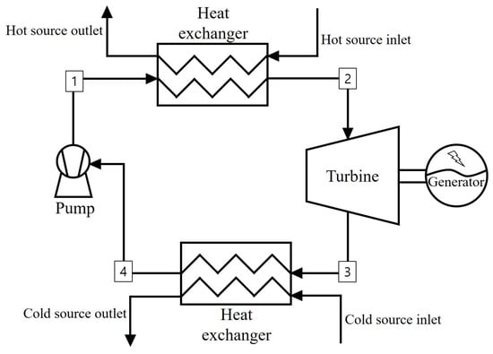
Figure 1.
Schematic illustration of the ORC system.

Table 1.
Thermodynamic data of R245fa (HFC-245fa).
The Carnot cycle efficiency (), which is the theoretical maximum value of the first-law efficiency, may be expressed using Equation (7).
where and denote the heat source and heat sink temperatures in the ORC system, respectively.
Exergy efficiency is the actual thermal efficiency of undergoing a completely reversible process, and may be calculated using Equation (8).
Table 2 lists the input conditions of the proposed ORC, based on the following assumptions. The turbine inlet temperature was set to 80 °C, which can be obtained through heat exchanging based on the heat source temperature of 90 °C.

Table 2.
Specification of the ORC.
- The system operates under steady-state conditions.
- The system is adiabatic with negligible heat losses.
- The pressure drop in the pipes is neglected.
- The mechanical efficiency of the system is neglected.
3. Design of the Turbine for the TEG
3.1. Concept of TEG
Figure 2a illustrates the structure of the conventional single-stage axial-flow turbine and generator in the ORC. The axial turbine comprises a stator and rotor that are supported by a hub, whereas the generator comprises only a stator and rotor. As depicted in the rotation frame (Figure 2a), the turbine and generator rotors are connected by a shaft, to rotate both rotors simultaneously. At least two bearings are coupled to the shaft for rotation. Thus, as the working fluid passes through the turbine stator and rotor, the turbine and generator rotors rotate, owing to the expansion of the pressure of the working fluid to generate electrical power. Figure 2b illustrates the structure of the proposed TEG. Herein, the turbine rotor is embedded inside the generator rotor, which results in simultaneous rotations of the two rotors when the working fluid passes through the turbine stator. The structure of the TEG constitutes the turbine generator with only one bearing, and can change the flow path of the working fluid that has passed through the turbine from radial to serial.
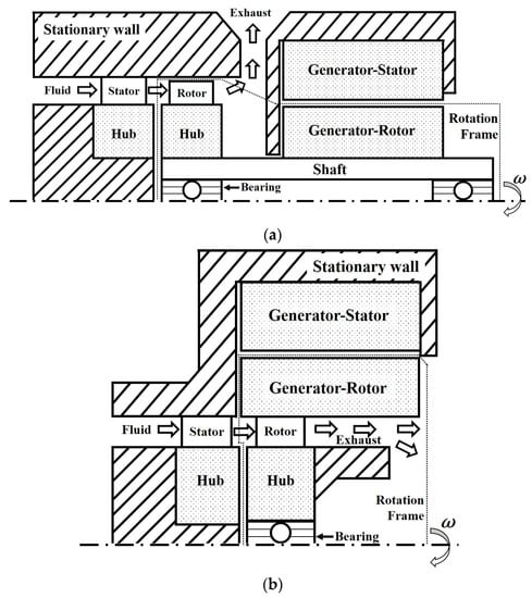
Figure 2.
Turbine generator structure in the ORC system. (a) Conventional type: The generator rotor is rotated using the turbine rotor torque through the shaft. (b) Proposed turbine embedded in a generator (TEG) type. The generator rotor is rotated using the rotation of the turbine rotor without a shaft.
3.2. Turbine Design Procedure
3.2.1. Mean-Line Design Method
To design the axial turbine applied to the TEG, a one-dimensional (1D) mean-line design was performed in the preliminary stage. The mean-line indicates the values of the mid-span of the turbine blade, and the velocity at the blade inlet and outlet may be calculated using dimensionless parameters such as flow and loading coefficients, and degree of reaction. Therefore, the performance of the turbine may be predicted in the preliminary stage based on the design results of the mean-line method.
The mean-line design method has been introduced by several researchers. Tournier and El-Genk [17] designed a six-stage, 530-MW helium axial turbine based on mean-line through-flow analysis of the free-vortex flow along the blade. The results showed the polytropic efficiency of the turbine with respect to the flow coefficient, work coefficient, and stage reaction. Al Jubori et al. [10] investigated the efficiency of a small-scale two-stage axial turbine using an integrated methodology of preliminary mean-line design and 3D computational fluid dynamics analysis. They reported a procedure for obtaining turbine layout in terms of velocity triangles, size, blade shape, and height. In addition, the mean-line design procedure for a single-stage axial turbine was developed to determine the optimum turbine geometry and efficiency under various operating conditions. Furthermore, a new general map was presented to predict the variation of turbine efficiency with flow and loading coefficients, specific speed, and specific diameter [18,19].
3.2.2. Velocity Triangle and Dimensionless Parameters
The flow coefficient (), loading coefficient (), and degree of reaction () are the representative dimensionless parameters in the mean-line-based turbine design. These may be calculated using Equations (9)–(11) [20] as follows.
where denotes the axial velocity, indicates the tangential velocity of the turbine rotor, represents the mean radius of the blade, denotes the angular velocity, and indicates the difference in the total enthalpy at the turbine inlet and outlet. The degree of reaction, as shown in Equation (11), may be defined as a pressure drop of the rotor over the pressure drop of the turbine stage.
Figure 3 depicts the velocity triangle of the turbine stator and rotor, which represents the two velocity components of the working fluid passing through the stator and rotor. It includes absolute velocity and relative velocity with and denoting the angles between the meridional plane and and , respectively. In addition, a chord represents the straight-line length for the blade leading edge and trailing edge, and an axial chord length indicates the axial length of the blade (Figure 3). The magnitudes of velocities and the angle of the velocity triangle at the stator inlet, rotor inlet, and rotor outlet are calculated using Equations (12) and (13) [21] as follows.
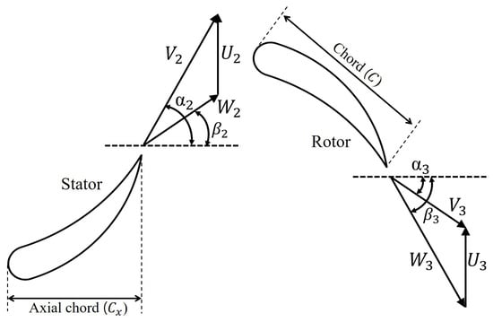
Figure 3.
Turbine blade geometry and typical velocity triangle for the axial-flow turbine blades.
3.2.3. Turbine Loss Model
The total pressure losses that occur within the blade passage must be considered in the preliminary stage because the magnitude of various pressure losses can directly affect turbine isentropic efficiency. Thus far, several studies have been conducted to predict and analyze the losses of turbine blades [22,23,24,25]. In the present study, blade losses for the TEG turbine were calculated by considering the overall loss system of Kacher and Okapuu [26], which is a modification of the Ainley/Mathieson/Dunham/Came loss system [22,23]. Therefore, as indicated in Equation (14), the total pressure loss coefficient is defined as the sum of four loss coefficients, namely the profile loss (), secondary loss (), tip clearance loss (), and trailing edge loss (). The profile loss, is directly associated with the growth of the boundary layer on the blade surface, and thus the separation of the boundary layer owing to the reverse pressure gradient on the surface increases the profile losses [27]. In addition, the is generated by the vortex caused by the cross-flow in the blade passage. Consequently, secondary vortices occur in the stream-wise direction, which can affect profile and annulus losses [27]. The is then generated, owing to the tip clearance between the moving blade and casing. Tip leakage loss is a major cause of turbine inefficiency in the case of unshrouded rotor blades [26,27]. The is expressed as a coefficient of kinetic energy loss and a function of the trailing edge thickness ratio to the blade throat [26]. Table 3 summarizes the equations of the aforementioned loss coefficients.

Table 3.
Equations of loss coefficient (profile, secondary, trailing edge and tip clearance).
3.2.4. Flow Chart of the Turbine Design
Figure 4 illustrates a flowchart of the mean-line design process of the turbine utilized in the present study. Initially, we determine the states of the working fluid, namely the total temperature, total pressure, and mass flow rate at the inlet of the turbine in the ORC as input data. In this case other values, such as the power, rotation speed, and dimensionless parameters were also provided as design conditions. Subsequently, the velocity triangle was calculated using Equations (12) and (13) [21], and the mean radius of the blade () was derived using Equation (9) [28]. Thermodynamic properties at the blade inlet and outlet may be obtained using the NIST REFPROF software. In addition, geometrical values, such as chord, axial chord, and pitch are designed using the in-house code to ensure a minimum loss coefficient () within the range that satisfies the input values of dimensionless parameters associated with the geometry, such as aspect ratio, blade solidity, and Zweifel coefficient. The recommended value for the aspect ratio, which is the ratio of the height to the chord length of the blade, is between 1.0 and 2.0 for a typical turbine stage [29]. Blade solidity (σ) denotes the ratio of the chord length to the pitch of the blade, and the ideal σ for optimum efficiency ranges approximately from 1.2 to 1.8 [30,31]. The Zweifel coefficient (Z) is the ratio of the actual tangential force to the ideal force acting on the blade. Although the optimum value for Z is approximately 0.75 to 0.85, most current turbine blades are designed for Z exceeding 1.0 [32]. To identify the optimal geometrical values for minimizing Y using the in-house code developed for this study, a generalized reduced-gradient algorithm was used for non-linear programming. Finally, the off-design performance of the turbine and thermodynamic efficiency of the ORC were calculated based on the designed turbine geometrical dimensions.
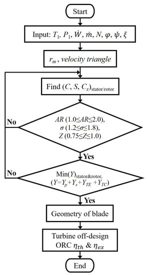
Figure 4.
Design procedure flowchart of axial-flow turbine blades for the mean-line.
4. Results and Discussion
4.1. Mean-Line Design Validation
The reliability of the mean-line design method used was verified based on the obtained turbine efficiency result from an experiment in [33]. The turbine efficiency was derived from the mean-line design using the specified turbine geometry dimensions in [33]. Based on this, the mean-line design results and previous experimental results were compared in terms of turbine efficiency (Figure 5). The turbine efficiency as a function of the flow coefficient that was obtained in the present study agrees with that of previous experimental data, which determined by considering the 3D blade geometry of previous experiments [33], as shown in Figure 5. Both results show that the peaks of efficiencies are close to the flow coefficient of 0.48, wherein turbine efficiency is determined to be 0.79 and 0.82 from the mean-line design and experimental results, respectively. The error between these is approximately 3.80%. It is noted that the turbine performance in the case of mean-line design is predicted based on the 1D blade in the present study. In other words, 3D blade geometry effects are not considered in our calculations. Therefore, we presumed that this error was because of the 3D blade geometry effect.
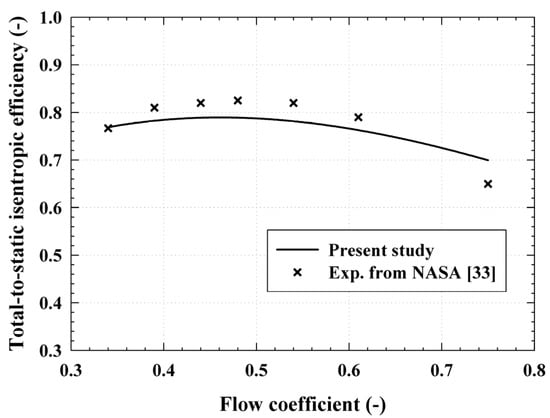
Figure 5.
Comparison of the mean-line design results investigated in the present study and previously reported experimental results [33].
4.2. Parametric Analysis
In the proposed TEG, as the turbine rotor should be coupled to the generator rotor, we designed a small-scale single-stage axial-flow turbine. Table 4 shows the parameters used for the mean-line design of the turbine blade rotor and the corresponding results. The values of the dimensionless numbers of flow coefficient (), loading coefficient (), and degree of reaction () at the design point for this calculation are, 0.7, 1.0, and 0.5, respectively. The Smith chart [34] was referred to for dimensionless number selection, which is a graph that presents turbine efficiency according to the relationship between and . Meanwhile, the off-design, which is a common procedure in turbine design was also performed. The off-design predicts changes in turbine performance when the turbine is operated out-of-design point, and it can be used to improve turbine performance. The off-design results for the designed turbine are shown in Figure 6, Figure 7, Figure 8 and Figure 9. As previously described in a flowchart (Figure 5), in order to design the turbine using the mean-line method, conditions such as temperature and pressure at the turbine inlet, mass flow rate (), turbine power (, and rotation speed (N), must first be chosen [16]. However, in the off-design stage, performance factors such as the total-to-total pressure ratio (PR), absolute Mach number (Ma), turbine total-to-total isentropic efficiency (), were analyzed by changing and values based on the turbine blade geometry in Table 4. In this case, the rotation speed is 20,000 rpm, = 0.5, and turbine inlet conditions are shown in Table 2.

Table 4.
Mean-line design results for rotor blade of single-stage axial-flow turbine.
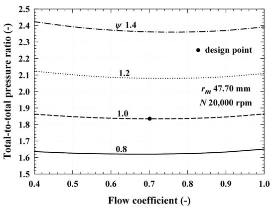
Figure 6.
Total-to-total pressure ratio (PR) of the turbine when the flow coefficient () ranges from 0.4 to 1.0 and loading coefficient () ranges from 0.8 to 1.4.
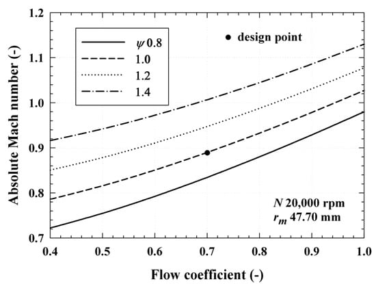
Figure 7.
Absolute Mach number (Ma) at the turbine stator outlet when the flow coefficient () ranges from 0.4 to 1.0 and loading coefficient () ranges from 0.8 to 1.4.
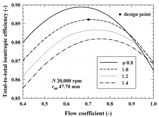
Figure 8.
Total-to-total isentropic efficiency of the turbine () when the flow coefficient () ranges from 0.4 to 1.0 and loading coefficient () ranges from 0.8 to 1.4.
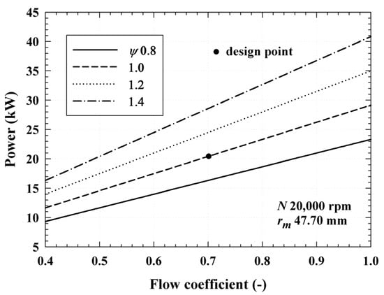
Figure 9.
Power of the turbine () when the flow coefficient () ranges from 0.4 to 1.0 and loading coefficient () ranges from 0.8 to 1.4.
To perform the off-design stage, the ranges of and were set to 0.4–1.0 and 0.8–1.4, respectively. The Smith chart [34] was referred to in choosing the ranges of and . Figure 6 shows the change in PR of the turbine according to for various given the rotational speed. In the case of PR, a higher PR was formed as was larger when was constant. This is because according to Equation (10), the difference of total enthalpy () increases as increases under the conditions of constant turbine size and rotational speed. As and PR are proportional [20], as increases, PR also increases. Therefore, the PR of the turbine designed at the design point is 1.83; however, the performance can be calculated under different PR conditions by changing and .
Figure 7 shows the variation of the absolute Mach number (Ma) at the outlet of the turbine stator according to for various . Ma is defined as , and is the sound speed of the fluid. This is a criterion to distinguish between supersonic flow (1 > Ma) and subsonic flow (1 < Ma). If supersonic flow occurs, the friction loss increases owing to the acceleration flow around the turbine blade, which reduces turbine efficiency [24]. As and increased as shown in Figure 7, Ma also increased. In this case, when is constant, the increase in means an increase in according to Equation (9), and the increase in means an increase in PR as shown in Figure 6. The single-stage axial-flow turbine designed in the present study is a subsonic turbine, and Ma is approximately 0.89 at the design point. If and PR continue to increase, the fluid at the stator outlet can reach supersonic flow. However, the actual turbine first reaches the supersonic flow at the blade throat [20], and this effect is omitted in 1D mean-line design. Therefore, a higher Ma may appear in the blade throat rather than at the stator outlet in the present study.
Figure 8 shows the total-to-total isentropic efficiency of the turbine () according to and . In the case of the designed turbine, the producing the peak efficiency was different according to , where the lower the , the higher the peak efficiency. At the design point, is approximately 0.89, which is close to the peak efficiency at = 1.0. As a result, the higher could be expected as was smaller between 0.4 and 0.8, which is similar to the turbine efficiency according to and that is presented in the Smith chart [34].
Figure 9 shows the turbine power () as a function of and as increases. Here, gradually improved. As increases in proportion to and according to Equation (2), if is constant, increases as and increase. In this case, when the results for PR shown in Figure 6 are applied, improves as PR increases. However, as the turbine designed here is a subsonic turbine, the PR cannot be continuously increased. As a result, the turbine PR, and are 1.83, 2.02 kg/s, and 20.42 kW, respectively, at the design point ( = 0.7, = 1.0, Ma = 0.89). Meanwhile, as an example, the turbine PR, and are 2.08, 2.31 kg/s, and 28.01 kW, respectively, at the off-design point ( = 0.8, = 1.2, Ma = 0.99).
Furthermore, the characteristics of the proposed TEG may be explained by analyzing its off-design performance. Based on the characteristics of the TEG described in Section 3.1, the turbine rotor applied to the TEG is integrated with the generator rotor; thus, the tip clearance loss coefficient () may be omitted. Therefore, and were analyzed according to the presence or absence of . To consider the effect of on turbine performance under the same PR condition, the values of and were first adjusted. In this case, the values for and were selected based on the absolute flow angle of 55.01° at the stator outlet [35]. Thus, was constantly increased from 0.4 to 1.0, and also increased from 0.14 to 1.85. Moreover, the tip clearance height (τ) was set to 0.5 mm to calculate the . Figure 10 shows according to PR. When is omitted, is 0.94 at the turbine PR of 1.83, which shows an improvement of approximately 5.62% compared to 0.89 at the design point. Figure 11 also shows the according to PR. Under the same conditions as for Figure 10, is 22.03 kW, which shows an improvement of approximately 7.88% compared to at the design point. As a result, and were improved owing to the omission of . Moreover, as the value of τ increased, so too did the effect of , and it is expected that the improvement range of and would increase further.
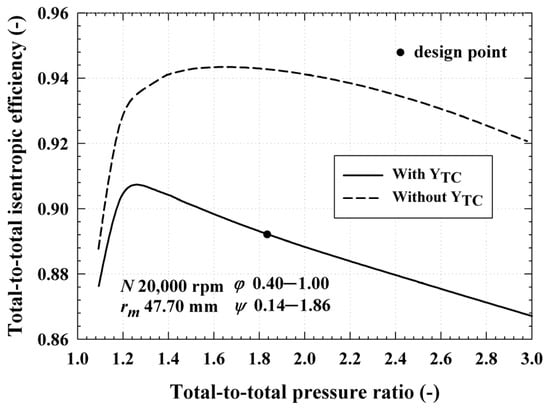
Figure 10.
Total-to-total isentropic efficiency of the turbine () with and without the tip clearance loss coefficient () when the total-to-total pressure ratio (PR) ranges from 1.0 to 3.0.
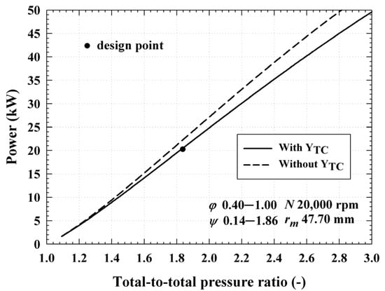
Figure 11.
Power of the turbine () with and without the tip clearance loss coefficient () when the total-to-total pressure ratio (PR) ranges from 1.0 to 3.0.
4.3. Thermal Efficiency of ORC
Figure 12 depicts the thermal efficiency () and exergy efficiency () of the ORC for the proposed TEG application. The input conditions of the ORC are listed in Table 2. The application of the TEG reflected the results of the turbine performance based on the presence or absence of , as illustrated in Figure 10 and Figure 11. First, if is not applied to the turbine performance, ORC is 4.81%, and is 19.28% at the design point. In this case, the temperature at the condenser outlet is 53.4 °C, the net power () is 18.72 kW, the evaporation heat capacity is 389.5 kW, and the condensation heat capacity is 369.77 kW. Conversely, when is applied to the turbine, is 5.08% and is 26.38%. In this case, the mass flow rate is 2.06 kg/s, is 20.03 kW, the evaporation heat capacity is 397.85 kW, and condensation heat capacity is 376.51 kW. In the above two cases, the PR of the turbine is 1.83, respectively, therefore, the temperature at the condenser outlet was set to 53.4 °C. As a result, the ORC and in the case where the TEG was applied were improved by 5.61%, compared to the case that excludes the TEG. Therefore, the efficiency of the ORC can be improved by changing the structure of the turbine generator. For this reason, it is expected that LCOE may be decreased by reducing manufacturing cost and improving electrical power of the ORC.
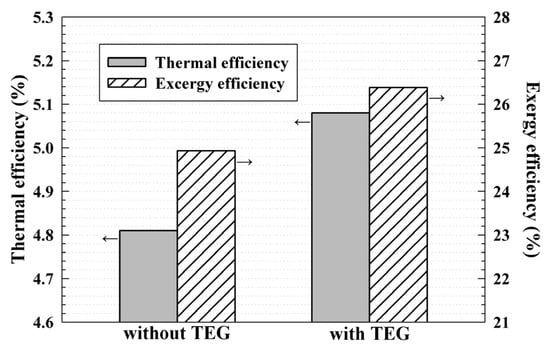
Figure 12.
Comparison of thermal and exergy efficiency of the ORC based on the application of the proposed TEG.
4.4. 3D Turbine Generator Assembly
Figure 13 shows the 3D assembly of the turbine generator with the structure of the TEG in the present study. The 3D assembly includes the turbine stator, rotor, generator stator and generator rotor where only a single bearing is placed. As the turbine rotor is coupled to the inside of the generator, it can rotate with only one bearing. Therefore, the structure is simple compared to the conventional turbine generator, and thus manufacturing cost can be reduced. In addition, because the shaft connecting the turbine and generator rotor can be omitted, the stability of the shaft system may be improved, and turbine generator volume can be reduced. Furthermore, as mentioned in Section 3.1, the structure of the proposed TEG does not require an additional exhaust pipe because the working fluid that has passed through the turbine can be discharged in the serial direction.
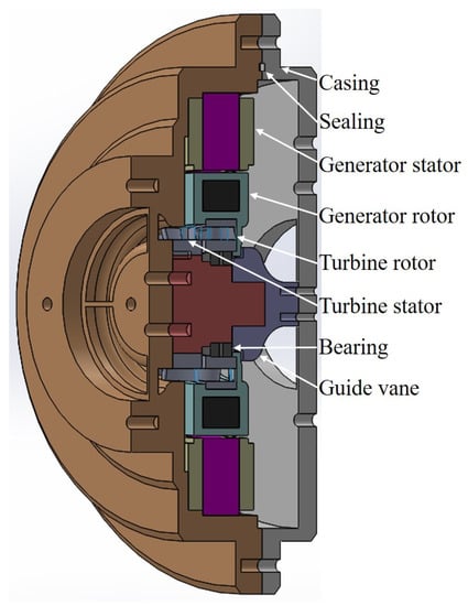
Figure 13.
Proposed 3D turbine generator assembly with TEG structure.
5. Conclusions
In a conventional turbine generator that is applied to an ORC, the power of the turbine is transmitted to the generator using a shaft. The TEG proposed in the present study can be described as a novel type of turbine generator, wherein the turbine rotor is embedded in the generator rotor. Unlike the traditional structure of the turbine generator, the TEG uses only one bearing, thus it signifies a simplification of the structure. It could also improve the stability of the shaft system, and we expect that the use of the proposed TEG would reduce manufacturing costs. In addition, as the tip clearance loss of the turbine rotor may be eliminated, the proposed TEG improves isentropic turbine efficiency. A single-stage axial-flow turbine was designed by mean-line analysis using the NIST REFPROP database, and turbine off-design performance prediction was conducted based on the flow coefficient, loading coefficient, and tip clearance loss coefficient. When tip clearance loss coefficient was considered, the power was 20.42 kW with a turbine isentropic efficiency of 0.89, and the ORC thermal efficiency was 4.81%. Meanwhile, the power and isentropic efficiency of the turbine when not considering the tip clearance loss coefficient were 22.03 kW and 0.94, respectively, and the thermal efficiency of the ORC was 5.08%. Therefore, the proposed TEG structure improved the thermal efficiency of the ORC, solely through changes to the structure of the turbine generator and regardless of operating conditions and type of working fluid used. Furthermore, a 3D assembly of the turbine generator including the structure of the TEG was proposed. In order to verify the proposed solution, in future work, we plan to design a 3D turbine blade, and test a lab-scale ORC system that adopts the proposed TEG structure.
Author Contributions
Conceptualization, J.-B.S. and Y.W.K.; methodology, J.-B.S. and Y.W.K.; software, J.-B.S.; validation, J.-B.S.; formal analysis, J.-B.S. and S.-J.Y.; investigation, J.-B.S.; resources, J.-B.S.; data curation, J.-B.S. and S.-J.Y.; writing—original draft preparation, J.-B.S.; writing—review and editing, J.-B.S. and Y.W.K.; visualization, J.-B.S.; supervision, Y.W.K.; project administration, J.-B.S. and Y.W.K.; funding acquisition, Y.W.K.; All authors have read and agreed to the published version of the manuscript.
Funding
This research was funded by the Ministry of Oceans and Fisheries, Korea.
Institutional Review Board Statement
Not applicable.
Informed Consent Statement
Not applicable.
Data Availability Statement
Not applicable.
Acknowledgments
This research was a part of the project titled ‘The development of marine-waste disposal system optimized in an island-fishing village’.
Conflicts of Interest
The authors declare no conflict of interest.
Nomenclature
| Blade chord length, m | |
| Blade axial chord length, m | |
| Specific total enthalpy, kJ/kg | |
| Blade height, m | |
| Mass flow rate (MFR), kg/s | |
| P | Pressure, Pa |
| Heat transfer rate, kW | |
| Blade radius, m | |
| S | Blade pitch, m |
| T | Temperature, K |
| Tangential velocity, m/s | |
| Absolute velocity, m/s | |
| Meridional velocity, m/s | |
| W | Relative velocity, m/s |
| W | Power, kW |
| Y | Total pressure loss coefficient |
| Greek Symbols | |
| α | Absolute flow angle |
| β | Relative flow angle |
| η | Efficiency |
| ξ | Degree of reaction |
| σ | Blade solidity (C/S) |
| τ | Tip clearance height, m |
| φ | Flow coefficient |
| ψ | Loading (work) coefficient |
| ω | Angular velocity, 1/s |
| Subscrips | |
| 1−4 | state point in ORC |
| Carnot | |
| Evaporation | |
| Exergy | |
| High | |
| L | Low |
| Mean value of the blade | |
| Pump, profile loss | |
| s | Isentropic, secondary loss |
| t | Turbine |
| TC | Tip clearance loss |
| TE | Trailing edge |
| th | Thermal |
| 0 | total |
| 1 | Inlet of the stator |
| 2 | Inlet of the rotor |
| 3 | Outlet of the rotor |
References
- Hung, T.C. Waste heat recovery of organic Rankine cycle using dry fluids. Energy Convers Manag. 2001, 42, 539–553. [Google Scholar] [CrossRef]
- Quoilin, S.; Lemort, V.; Lebrun, J. Experimental study and modeling of an Organic Rankine Cycle using scroll expander. Appl. Energy 2010, 87, 1260–1268. [Google Scholar] [CrossRef]
- Barse, K.A.; Mann, M.D. Maximizing ORC performance with optimal match of working fluid with system design. Appl. Eng. 2016, 100, 11–19. [Google Scholar] [CrossRef] [Green Version]
- Wei, D.; Lu, X.; Lu, Z.; Gu, J. Performance analysis and optimization of organic Rankine cycle (ORC) for waste heat recovery. Energy Convers Manag. 2007, 48, 1113–1119. [Google Scholar] [CrossRef]
- Li, Y.R.; Wang, J.N.; Du, M.T. Influence of coupled pinch point temperature difference and evaporation temperature on performance of organic Rankine cycle. Energy 2012, 42, 503–509. [Google Scholar] [CrossRef]
- Wang, J.; Yan, Z.; Wang, M.; Li, M.; Dai, Y. Multi-objective optimization of an organic Rankine cycle (ORC) for low grade waste heat recovery using evolutionary algorithm. Energy Convers Manag. 2013, 71, 146–158. [Google Scholar] [CrossRef]
- Kang, S.H. Design and experimental study of ORC (organic Rankine cycle) and radial turbine using R245fa working fluid. Energy 2012, 41, 514–524. [Google Scholar] [CrossRef]
- Declaye, S.; Quoilin, S.; Guillaume, L.; Lemort, V. Experimental study on an open-drive scroll expander integrated into an ORC (Organic Rankine Cycle) system with R245fa as working fluid. Energy 2013, 55, 173–183. [Google Scholar] [CrossRef]
- Lazzaretto, A.; Manente, G. A new criterion to optimize ORC design performance using efficiency correlations for axial and radial turbines. Int. J. Thermo. 2014, 17, 192–200. [Google Scholar] [CrossRef] [Green Version]
- Al Jubori, A.M.; Al-Dadah, R.; Mahmoud, S. An innovative small-scale two-stage axial turbine for low-temperature organic Rankine cycle. Energy Convers Manag. 2017, 144, 18–33. [Google Scholar] [CrossRef]
- Al Jubori, A.M.; Al-Mousawi, F.N.; Rahbar, K.; Al-Dadah, R.; Mahmoud, S. Design and manufacturing a small-scale radial-inflow turbine for clean organic Rankine power system. J. Clean. Prod. 2020, 257, 120488. [Google Scholar] [CrossRef]
- Giovannelli, A.; Archilei, E.M.; Salvini, C. Two-Stage Radial Turbine for a Small Waste Heat Recovery Organic Rankine Cycle (ORC) Plant. Energies 2020, 13, 1054. [Google Scholar] [CrossRef] [Green Version]
- Peng, N.; Wang, E.; Zhang, H. Preliminary Design of an Axial-Flow Turbine for Small-Scale Supercritical Organic Rankine Cycle. Energies 2021, 14, 5277. [Google Scholar] [CrossRef]
- Hu, S.; Yang, Z.; Li, J.; Duan, Y. A Review of Multi-Objective Optimization in Organic Rankine Cycle (ORC) System Design. Energies 2021, 14, 6492. [Google Scholar] [CrossRef]
- Wang, E.H.; Zhang, H.G.; Fan, B.Y.; Ouyang, M.G.; Zhao, Y.; Mu, Q.H. Study of working fluid selection of organic Rankine cycle (ORC) for engine waste heat recovery. Energy 2011, 36, 3406–3418. [Google Scholar] [CrossRef]
- Fernández-Guillamón, A.; Molina-García, Á.; Vera-García, F.; Almendros-Ibáñez, J.A. Organic Rankine Cycle Optimization Performance Analysis Based on Super-Heater Pressure: Comparison of Working Fluids. Energies 2021, 14, 2548. [Google Scholar] [CrossRef]
- Tournier, J.M.; El-Genk, M.S. Axial flow, multi-stage turbine and compressor models. Energy Convers Manag. 2010, 51, 16–29. [Google Scholar] [CrossRef]
- Da Lio, L.; Manente, G.; Lazzaretto, A. New efficiency charts for the optimum design of axial flow turbines for organic Rankine cycles. Energy 2014, 77, 447–459. [Google Scholar] [CrossRef]
- Da Lio, L.; Manente, G.; Lazzaretto, A. Predicting the optimum design of single stage axial expanders in ORC systems: Is there a single efficiency map for different working fluids? Appl. Energy 2016, 167, 44–58. [Google Scholar] [CrossRef]
- Moustapha, H.; Zelesky, M.F.; Baines, N.C.; Japikse, D. Axial and Radial Turbines; Concepts NREC: White River Junction, VT, USA, 2003. [Google Scholar]
- Wilson, D.G.; Korakianitis, T. The Design of High-Efficiency Turbomachinery and Gas Turbines; MIT Press: Cambridge, MA, USA, 2014. [Google Scholar]
- Ainley, D.G.; Mathieson, G.C.R. A Method of Performance Estimation for Axial-Flow Turbines; Aeronautical Research Council: London, UK, 1951. [Google Scholar]
- Dunham, J.; Came, P.M. Improvements to the Ainley-Mathieson method of turbine performance prediction. J. Eng. Power 1970, 92, 252–256. [Google Scholar] [CrossRef]
- Craig, H.R.M.; Cox, H.J.A. Performance estimation of axial flow turbines. Proc. Inst. Mech. Eng. 1970, 185, 407–424. [Google Scholar] [CrossRef]
- Zhu, J.; Sjolander, S.A. Improved profile loss and deviation correlations for axial-turbine blade rows. In Proceedings of the Turbo Expo: Power for Land, Sea, and Air; ASME: Reno, NV, USA, 2005; Volume 47306, pp. 783–792. [Google Scholar]
- Kacker, S.C.; Okapuu, U. A mean-line prediction method for axial flow turbine efficiency. J. Eng. Power 1982, 104, 111–119. [Google Scholar] [CrossRef]
- Patdiwala, U.J.; Patel, H.C.; Parmar, P.K. A review on tip clearance flow and secondary flow losses in linear turbine cascade. J. Mech. Civ. Eng. 2014, 11, 33–37. [Google Scholar] [CrossRef]
- Dixon, S.L.; Hall, C. Fluid Mechanics and Thermodynamics of Turbomachinery; Butterworth-Heinemann: Oxford, UK, 2013. [Google Scholar]
- Rist, D. Influence of geometric effects on the aspect ratio optimization of axial turbine bladings. In Proceedings of the Turbo Expo: Power for Land, Sea, and Air; ASME: London, UK, 1978; Volume 79726, p. V01BT02A072. [Google Scholar]
- Gao, K.; Xie, Y.; Zhang, D. Effects of rotor solidity and leakage flow on the unsteady flow in axial turbine. Appl. Therm. Eng. 2018, 128, 926–939. [Google Scholar] [CrossRef]
- Simpson, A.T.; Spence, S.W.T.; Watterson, J.K. Numerical and experimental study of the performance effects of varying vaneless space and vane solidity in radial turbine stators. J. Turbomach. 2013, 135, 031001. [Google Scholar] [CrossRef]
- Zweifel, O. The spacing of turbomachine blading, especially with large angular deflection. Brown Boveri. Rev. 1945, 32, 436–444. [Google Scholar]
- Kofskey, M.G.; Nusbaum, W.J. Aerodynamic Evaluation of Two-Stage Axial-Flow Turbine Designed for Brayton-Cycle Space Power System; National Aeronautics and Space Administration: Washington, DC, USA, 1968.
- Smith, S.F. A simple correlation of turbine efficiency. Aeronaut. J. 1965, 69, 467–470. [Google Scholar] [CrossRef]
- Nagpurwala, Q.H. Hydraulic Turbine; PEMP RMD 2501; M.S. Ramaiah School of Advanced Studies: Bengaluru, India, 2016; pp. 1–70. [Google Scholar]
Publisher’s Note: MDPI stays neutral with regard to jurisdictional claims in published maps and institutional affiliations. |
© 2022 by the authors. Licensee MDPI, Basel, Switzerland. This article is an open access article distributed under the terms and conditions of the Creative Commons Attribution (CC BY) license (https://creativecommons.org/licenses/by/4.0/).