Abstract
The paper presents an analytical discussion of how to improve the energy efficiency of the steam cushion system operation for a Thermal Energy Storage (TES) tank. The EU’s green deal 2050 target policy requires an increase in the energy efficiency of energy production and use, as well as an increase in the share of renewable energy in the overall energy production balance. The use of energy-efficient TES is considered as one of the most important technologies to achieve the objectives of this EU policy. The analyses presented in the paper of energy-efficient operation of steam cushion (SC) systems were carried out by using operational data received from three District Heating Systems (DHSs) that supply heat and electricity to one of the largest cities in Poland and are equipped with the TES systems. These three analyzed TESs differ in capacities from 12,800 to 30,400 m3, tank diameters from 21 to 30 m and shell height from 37 to 48.2 m. The main purpose of using a steam cushion system in the TES tank is to protect the water stored in it against the absorption of oxygen from the surrounding atmospheric air through the surge chamber and safety valves located on the roof of the tank. The technical solutions presented here for the upper orifice for charging and discharging hot water into/from the tank and the suction pipe for circulating water allow to us achieve significant energy savings in the steam cushion systems. Both the upper orifice and the end of suction pipe are movable through the use of pontoons. Thanks to the use of this technical solution, a stable insulating water layer is created above the upper orifice in the upper part of the TES tank, where convective and turbulent transport of heat from the steam cushion space to the hot water stored in the tank is significantly limited. Ultimately, this reduces the heat flux by approximately 90% when compared to the classic technical solutions of steam cushion systems in TES tanks, i.e., for the upper orifice and circulation water pipe. The simplified analysis presented in the paper and comparison of its results with experimental data for heat flow from the steam cushion space to hot water stored in the upper part of the TES tank fully confirms the usefulness of the heat-flow models used.
1. Introduction
District heating systems (DHSs) in Poland supply heat for more than 15 million inhabitants. The Polish District Heating sector has been undergoing intensive modernization and development since the 1990s. For the first two decades, the work focused mainly on replacing and modernizing elements of DHSs in order to improve their energy efficiency and reliability and reduce their environmental burden.
Over the last decade, this work has focused primarily on increasing the energy efficiency of DHSs by implementing cogeneration and tri-generation technologies (mainly based on coal [1,2], gas [3] and oil [4]), making the widest possible use of renewable energy sources [5,6] and implementing smart District Heating Networks in future sustainable energy systems [7,8,9,10,11,12]. Based on the abovementioned papers, it can be concluded that the intelligent district heating system has a number of advantages compared to the traditional heating system in many areas, including troubleshooting, energy saving, regulation and control. It also shows great development potential and broad market prospects in the future, especially in times of looking for savings both in terms of investment and the operation of heating systems. In 2018, as part of the “Clean energy for all Europeans package”, the new amending Directive on Energy Efficiency (2018/2002) was agreed to update the policy framework to 2030 and beyond [13,14,15]. To achieve these objectives, it is essential to implement Thermal Energy Storage (TES) systems in these already often advanced smart District Heating Networks (DHN). Without the uptake of TES technologies, it is difficult to imagine achieving the EU’s energy policy objectives, i.e., increasing the energy efficiency of all energy generation and use installations, increasing the share of renewables in the energy production balance sheet and reducing emissions of pollutants (green deal 2050 target).
Today, TES technologies [16,17,18,19,20,21,22] are recognized as one of the most important advanced energy technologies to correct the mismatches between energy supply and demand [23]. The most popular and easiest way to store heat in TES systems is to use so-called sensible thermocline TESs. Most often, these TESs are built as heat tanks operating at atmospheric pressure and hooked-up to the district heating network directly; that is, network water, both supply and return, fills the TES tank. In sensible TES, the stored energy is the result of a change in the temperature of the stored medium and its quantity; that is, the amount of stored energy is proportional to the temperature difference of hot and cold medium, the mass of the stored medium and its heat capacity [24,25].
The TES, which stores excess heat during periods of decline and provides heat during periods of increased demand by consumers, contributes to more energy efficient production and supply of energy to customers. TES technology offers great potential for significant improvements in DHS operating conditions [22]; in particular, the economics of heat and electricity production reduce gaseous pollutant emissions and increase security of energy supply to consumers. The TES also enables better integration and use of renewable energy sources, especially weather-dependent ones, which produce energy for DHS. Often the TES is part of the CHP systems, helping to optimize their operation [22].
At the moment, there are six large sensible TESs in the DHS in Poland, i.e., with a capacity of more than 10,000 m3 [26], the seventh is under construction and the next one is under design. In smaller DHSs, there are also several small (less than 1000 m3) and medium (less than 10,000 m3 and greater than 1000 m3) TES systems.
2. Materials and Methods
2.1. System Description
The energy analysis of the operation of the steam cushion (SC) system for the TES tank was carried out for three large DHSs in Poland that supply customers with heat from the following CHP plants:
- CHP plant Siekierki in Warsaw,
- CHP plant in Cracow,
- CHP plant in Białystok.
The CHP plants analyzed in the paper were furnished with the same type of TES, i.e., thermally stratified, sensible heat storages. All TES tanks are designed to operate under atmospheric pressure and are hooked up directly to the District Heating Network through the TES pumping station. Network water, which is stored in the TES tank, is protected against oxygen absorption from ambient air by a SC system. Photographs of the TES tanks for CHP plants in Warsaw, Cracow and Białystok are shown in Figure 1, Figure 2 and Figure 3, respectively.
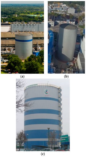
Figure 1.
TES in (a) Siekierki CHP plant in Warsaw, (b) Cracow CHP plant and (c) Białystok CHP plant.
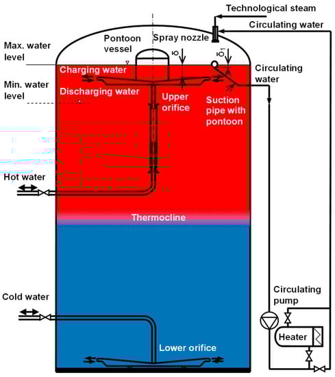
Figure 2.
Scheme of the TES tank equipped with SC system.
Operational data were collected and analyzed for three selected TES tanks equipped with SC systems of identical design. Short characteristic of the TES for each considered CHP plant are given below in Table 1.

Table 1.
Technical parameters of the TES in Warsaw, Cracow and Bialystok CHP plants [26].
The temperature of the TES charging water ranged from 84 to 97 °C for the TES analyzed and for different seasons.
2.2. Characteristics of the SC System
The operational task of the SC system in the TES tank is to protect stored network water against the absorption of oxygen from the surrounding atmospheric air. Water in the heating system must meet stringent purity standards. The oxygen content in this water is also very important. The TES tank, hydraulically connected to the heating system, is its integral element and is filled with the same water. If the amount of dissolved oxygen in the water is excessive, it causes corrosion of both the network and the TES tank and its equipment.
As a non-pressurized tank, the TES tank is exposed to oxygen ingress, e.g., through safety valves. Valves located on the roof protect the tank against excessive overpressure and negative pressure.
For the TES tanks presented in this article, the permissible vacuum should be less than −500 Pa, and the overpressure should not be more than +1500 Pa. The typical working pressure of steam in the steam bed is overpressure [27]:
psb = +500 Pa ± 100 Pa
The SC system consists of the following (Figure 2):
- Suction pipe for circulation water with inlet fixed to the pontoon,
- Circulation pump,
- Electrical water heater,
- Discharge pipe for circulation water,
- Spray nozzle,
- Technological steam supply system.
The scheme of the TES tank with steam cushion system is presented in Figure 2.
The SC system, which is located under the roof of the TES tank, works to protect the water stored in the tank against the absorption of oxygen from the surrounding atmospheric air [27,28]. The vapor pressure above the water level in the TES tank is generated by the injected technological steam. A water cycle is used to prevent the superheated steam from coming into contact with the water surface. The water circulation is forced by a circulating pump that feeds the spray nozzle. The water sprayed through the nozzle mixes with the steam to form the so-called “steam rain”. The entire process takes place between the roof of the TES tank and the water surface.
In the event that there is a lack of supply of spray nozzle with technological steam, steam rain will be produced from circulating water heated above 100 °C by an electric water heater. The electric water heater is an emergency device and overheats the water above boiling point for atmospheric pressure + several hundred Pa, prevailing in the space of the steam cushion. The temperature value to which the circulating water should be overheated is correlated with the operating pressure of the steam cushion; that is, it must maintain the set operating pressure, usually around +500 Pa.
Figure 3 shows the photograph of the upper orifice fixed to the pontoon vessel. The photograph was taken during the erection of the TES in the Siekierki CHP plant in Warsaw.
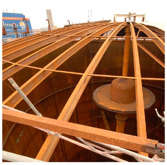
Figure 3.
Upper orifice in the TES tank in CHP Siekierki–Warsaw [28].
Figure 4, on the other hand, presents the main dimensions of the steam cushion systems for CHP Siekierki–Warsaw, CHP Cracow and CHP Bialystok plants.
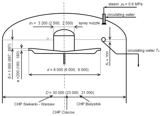
Figure 4.
Main dimensions of the steam cushion systems for CHP Siekierki–Warsaw, CHP Cracow and CHP Białystok plants.
A technical solution to reduce energy consumption by the SC system [27] on the example of the tank in CHP Białystok, indicating the operational parameters of the system, is shown in Figure 5.
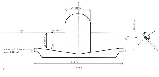
Figure 5.
Operational parameters of the SC system in the TES tank in the CHP Białystok.
3. Results
The results of the experimental and theoretical investigation of stratified hot-water storage tanks were presented by Dincer and Rosen [29] and Votsis [30]. The influence of the geometric parameters of the TES tank, including its inlet, on the maintenance of the thermocline in the TES tank has been the subject of various studies by Wildin [31,32,33], Zurigat et al. [34] and Jianhua et al. [35]. Murthy et al. [36] estimated that the heat flux transferred through the tank wall on stratification in the TES tank could be negligible.
The primary energy-savings analysis for the operation of the SC system for the TES tank was performed for the CHP plant in Białystok. An additional analysis confirming these results was performed for the TES tanks at the Siekierki CHP plant in Warsaw and in CHP plant in Cracow, which have approximately 2.4 and 1.6 tank volumes in Białystok, respectively. The three analyzed SC systems have the same technical structure.
Operational data for the steam cushion systems in these three CHP plants were collected for both heating and summer seasons. Special attention was paid to the so-called transition periods of the heating season, i.e., end of winter–spring and end of autumn–winter, where the fastest changes in heat demand by consumers are observed.
Figure 6 and Table 2 show selected operational data for the TES and steam cushion system in CHP Cracow for the period of 2.5 months, i.e., from 7 January 2021 to 18 March 2021.
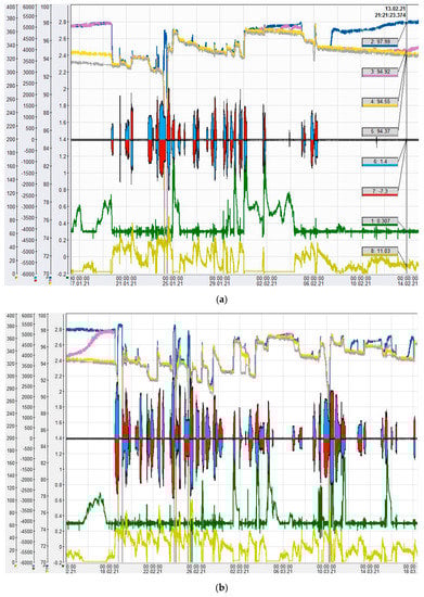
Figure 6.
Data for 2.5 months’ operation (from 7 January 2021 to 13 February 2021 (a) and from 14 February 2021 to 18 March 2021 (b)) of the TES with steam cushion system for CHP in Cracow.
Table 2.
Description of the signals (pressures, temperatures and flow rates) for 2.5 months’ operational data.
The data presented in the graph (Figure 6 and Table 2) of the hot-water temperature below the upper orifice level in the TES tank indicate that the temperature of this water is practically equal to the temperature of the water charging the tank.
Thus, the assumption taken in the calculation of heat loss in the space of the steam cushion, nearly the constant mixing temperature of hot water in the layer below the upper orifice, is a good approximation (see Figure 7 and Figure 8).
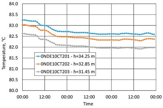
Figure 7.
Measured temperatures of stored hot water in the upper part of the TES tank during three selected 24-h periods (summer season, only storing process) for CHP Białystok.
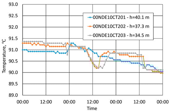
Figure 8.
Measured temperatures of stored hot water in the upper part of the TES tank during three selected 24-h periods (transition period, charging, storing and discharging processes) for CHP Siekierki in Warsaw.
The calculation of heat losses by the roof of the tank TES was carried out, the insulation of which consists of the following:
- DachrockMax (density 150 kg/m3, average thermal conductivity is assumed λ = 0.05 W/(m·K), thickness 480 mm (180 + 180 + 120 mm),
- MarineSlab (density 220 kg/m3, average thermal conductivity is assumed λ = 0.05 W/(m·K), thickness 30 mm,
- Protective insulation coating—sarnafil TS77-15 membrane cover with a thickness of 1.5 mm.
Thus, the total thickness of the roof insulation is 511.5 mm.
The heat conductivity equation for this multilayer wall was solved for the average annual outdoor air temperature in Bialystok, which is 11 °C. Unit heat loss for the above conditions is approximately 9.1 W/m2, which, for a spherical roof of approximately 257 m2, gives a total heat loss through the roof of the tank of about 2.1 kW (see Table 1 and Figure 9).
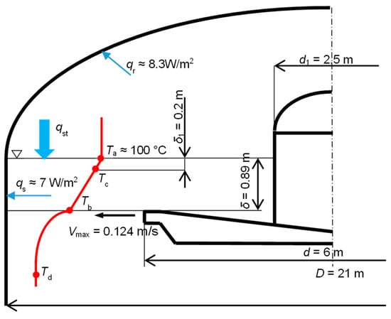
Figure 9.
Assumption for mathematical model for steam cushion system in Białystok CHP plant.
The calculation of heat losses by the shell tank with the height equal δ was carried out for shell insulation materials glass wool [λins ≈ 0.05 W/(m·K)], and thickness of insulation equals 500 mm. The unit heat loss for the above conditions is approximately 7.0 W/m2, which, for a cylindrical shell of approximately 58 m2, gives a total heat loss through the shell of the tank with a height of 0.89 m of about 0.4 kW (see Table 1 and Figure 9).
The temperature distribution in the insulating water layer (with thickness δ) of the SC system and further in the hot-water layer stored in the tank is shown in Figure 9.
Heat transfer from steam cushion space through interphase surface into the hot water stored in the upper part of the TES tank, assuming that convective and turbulent heat transport is significantly limited, could be calculated from the heat conductivity equation with an appropriate correction coefficient “iht”, as was presented in Reference [28].
The specific heat flux transferred from the steam cushion space from the condensing steam through an insulating layer of water with thickness “δ” to the hot water located at the top of the TES tank can be calculated from the following equation:
where λ ≅ 0.68 W/(m·K) is the average value of the heat conduction coefficient for water; Ta are Tb are the temperature of the interphase surface of the water in contact with the steam cushion and temperature of the water in the tank at the depth δ, respectively (Figure 9); Tc is the temperature of the water in the insulating water layer at the depth δ1 (suction pipe inlet of circulation water); and iht is the intensity of the heat transport coefficient in the water insulating layer.
The coefficient iht indicates how intensive the heat transfer is in comparison to the heat conduction in the water insulating layer. This coefficient takes into account the intensity of convective and turbulent heat transport.
This coefficient iht should have an as-small-as-possible value in order to reduce technological steam consumption in the SC system. If the coefficient iht = 1, it means that heat transport is by conduction only.
The temperature distribution in the boundary layer and further in the hot-water layer stored in the tank is shown in Figure 9.
From the lower part of the water buffer layer, heat is transferred to the hot water stored in the tank. During the process of charging and discharging the TES, there is a flow of water (flowing out of the lower orifice and flowing into this orifice, respectively) along the lower part of the water buffer layer. To describe the process of heat transfer from the lower part of the water buffer layer to the water stored in the upper part of the tank, the equation for the Nusselt number as for the flow over the flat plate was used:
where the A, B and C are presented in Table 3:
Finally,
and
where
Table 3.
Nusselt equation coefficients for laminar and turbulent flow.
The use of the technical solution of the SC system presented in Figure 2, Figure 3, Figure 4 and Figure 5 enables a significant reduction in the value of the iht coefficient in comparison with a typical construction of the upper orifice and inlet of the suction pipe.
As shown in References [27,28], the estimated average values of the coefficient of heat transport intensity iht are as follows:
- iht ≅ 4.5 (for presented technical solution of upper orifice and inlet of the suction pipe for circulation water),
- iht ≅ 50 (for non-movable upper orifice and suction pipe).
Below, for selected operational data, two different operation cases (charging and discharging the TES) of the SC system were analyzed for the CHP plant in Bialystok. Operational data taken into considerations are as follows:
—saturation temperature in the steam bed,
—temperature of circulation water,
—temperature of charging/discharging water (),
—flow rate of charging/discharging water,
CT201, 202 and 203—temperatures of stored hot water in the TES tank (taken from the temperature sensors placed along the tank shell on different height).
- (1)
- Charging the TES:
Data:
Ta = 100 °C, Tc = 98 °C, Te = 90 °C, = 499 m3/h, iht = 4.5,
λ = 0.68 W/(m·K), ν = 0.326 × 10⁻⁶ m2/s, Pr = 1.95,
D = 21 m, d = 6 m, d1 = 2.5 m, δ = 0.887 m, δ1 = 0.2 m, e = 0.18 m.
Total gap area (outlet/inlet) in the upper orifice:
Velocity of the charging water:
The temperatures of stored hot water in the TES tank measured by the temperature sensors were as follows (level of stored water in the TES tank is 37 m):
| CT201 (located at a height 34.25 m) | 90.84 °C; |
| CT202 (located at a height 32.85 m) | 90.60 °C; |
| CT203 (located at a height 31.45 m) | 90.19 °C. |
- (2)
- Discharging the TES:
Data:
Ta = 100 °C, Tc = 95.7 °C, Te = 78.2 °C, = 519 m3/h, iht = 4.5,
λ = 0.673 W/(m·K), ν = 0.37·10−6 m2/s, Pr = 2.3,
D = 21 m, d = 6 m, d1 = 2.5 m, δ = 0.887 m, δ1 = 0.2 m, e = 0.18 m.
Total gap area (outlet/inlet) in the upper orifice:
Velocity of the charging water:
The temperatures of stored hot water in the TES tank measured by the temperature sensors were as follows:
| CT201 (located at a height 34.25 m) | 78.85 °C; |
| CT202 (located at a height 32.85 m) | 78.05 °C; |
| CT203 (located at a height 31.45 m) | 77.32 °C. |
The presented measurement results (taken from SCADA systems) for three selected TES systems in Warsaw, Białystok and Cracow indicate that the operation of steam cushion systems with the structure given above is stable and the adopted calculation models are correct. The temperatures of hot water stored in the upper part of the TES tank calculated and measured differ slightly, i.e., by tenths of a °C (Figure 10a,b).
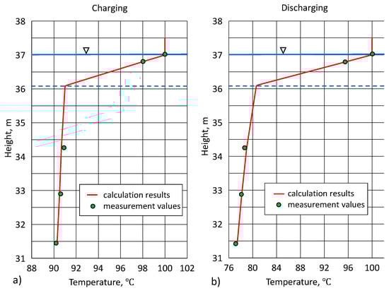
Figure 10.
Comparison of calculation results with measurement data for heat transfer from the steam cushion space to the hot water stored in the upper part of the TES tank for Białystok CHP plant: (a) charging process of the TES and (b) discharging process of the TES.
The unit heat flux in the conditions of stabilized operation of the steam cushion system, for heat transferred from the steam cushion space to the hot water stored in the upper part of the TES tank, varies within the following limits:
The lower limit of the unit heat flux refers to the high temperatures of stored hot water (Te = 97–98 °C) and circulating water (Tc ≈ 99 °C), while the upper limit refers to the low temperatures of stored hot water (Te ≈ 70 °C) and circulating water (Tc ≈ 94 °C). Thus, usually low values of the unit heat flux occur during the heating season, and high in the summer season, when it may happen that the stored hot water has a temperature of about 70 °C.
In order to calculate the total heat consumption in the steam cushion system, it is necessary to take into account the sizes of the unit heat loss flux through the roof of the tank and through the tank shell in the area of the insulating water layer with a thickness δ. In the analyzed case, these two quantities were calculated for the average temperature of the outside air and specific insulating materials of the roof and shell of the tank and the geometrical dimensions of the tank TES in Bialystok (see Figure 5 and Figure 9).
4. Discussion
The steam cushion system saves energy thanks to the innovative floating upper orifice and circulating water pipe inlet. This is performed by means of floating elements that change their height with the height of the water surface. Where an upper orifice is used, an insulating water layer is formed at the top of the tank with very limited convective and turbulent heat transport, thus resulting in limited heat transfer from the steam cushion space to the water stored in the tank. The thickness of the insulating water layer, which separates the water surface from the rest of the water in the TES tank, is usually from 0.8 to 1 m [28].
Water is a good insulator, with an average thermal conductivity of approximately 0.68 W/(m K). In order to minimize convective and turbulent heat transport in the insulating water layer, the heat flux from the condensing steam should be limited. In this case, the heat flux constitutes about 10% of the heat flux present in a typical technical solution of the upper orifice and the suction pipe of the circulating water in the TES tank [26].
The simplified analysis presented in the paper and comparison of its results with experimental data for heat flow from the steam cushion space to hot water stored in the upper part of the TES tank fully confirm the usefulness of the heat flow models used hereto.
The unit heat flux in the conditions of stabilized operation of the steam cushion system, for heat transferred from the steam cushion space to the hot water stored in the upper part of the TES tank, varies within the limits of . Usually, a low limit of the unit heat flux occurs during the heating season, and a high one occurs in the summer season, when it may happen that the stored hot water has a temperature of about 70 °C.
In order to calculate the total heat consumption in the steam cushion system, it is necessary to take into account the sizes of the unit heat loss flux through the roof of the tank and through the tank shell in the area of the insulating water layer with a thickness δ. For example, the average fluxes of these heat losses were calculated ( and ) for the SC system for the TES tank in Białystok and given in Figure 9.
Author Contributions
Conceptualization, R.Z.; methodology, R.Z.; validation, R.Z. and O.N.; formal analysis, R.Z. and M.W.; investigation, R.Z., O.N. and M.W.; resources, R.Z.; data curation, R.Z. and O.N.; writing—original draft preparation, R.Z. and M.W.; writing—review and editing, R.Z., O.N. and M.W.; visualization, R.Z. and O.N.; supervision, R.Z. All authors have read and agreed to the published version of the manuscript.
Funding
This research received no external funding.
Institutional Review Board Statement
Not applicable.
Informed Consent Statement
Not applicable.
Conflicts of Interest
The authors declare no conflict of interest.
References
- Zhang, Q.; Gao, J.; Wang, Y.; Wang, L.; Yu, Z.; Song, D. Exergy-based analysis combined with LCA for waste heat recovery in coal-fired CHP plants. Energy 2019, 169, 247–262. [Google Scholar] [CrossRef]
- Liu, H.; Geng, Z.; Gu, Y.; Mo, Z.; Yu, Z.; He, X.; Lu, S. A regional integrated energy system with a coal-fired CHP plant, screw turbine and solar thermal utilization: Scenarios for China. Energy Convers. Manag. 2020, 212, 112812. [Google Scholar] [CrossRef]
- Yan, B.; Xue, S.; Li, Y.; Duan, J.; Zeng, M. Gas-fired combined cooling, heating and power (CCHP) in Beijing: A techno-economic analysis. Renew. Sustain. Energy Rev. 2016, 63, 118–131. [Google Scholar] [CrossRef] [Green Version]
- An, J.; Mikhaylov, A.; Jung, S.-U. The Strategy of South Korea in the Global Oil Market. Energies 2020, 13, 2491. [Google Scholar] [CrossRef]
- An, J.; Mikhaylov, A. Russian energy projects in South Africa. J. Energy South. Afr. 2020, 31, 58–64. [Google Scholar] [CrossRef]
- Vakulchuk, R.; Overland, I.; Scholten, D. Renewable energy and geopolitics: A review. Renew. Sustain. Energy Rev. 2020, 122, 109547. [Google Scholar] [CrossRef]
- Ma, Z.; Knotzer, A.; Billanes, J.D.; Jørgensen, B.N. A literature review of energy flexibility in district heating with a survey of the stakeholders’ participation. Renew. Sustain. Energy Rev. 2020, 123, 109750. [Google Scholar] [CrossRef]
- Gao, L.; Cui, X.; Ni, J.; Lei, W.; Huang, T.; Bai, C.; Yang, J. Technologies in Smart District Heating System. Energy Procedia 2017, 142, 1829–1834. [Google Scholar] [CrossRef]
- Novitsky, N.N.; Shalaginova, Z.I.; Alekseev, A.A.; Tokarev, V.V.; Grebneva, O.A.; Lutsenko, A.V.; Vanteeva, O.V.; Mikhailovsky, E.A.; Pop, R.; Vorobev, P.; et al. Smarter Smart District Heating. Proc. IEEE 2020, 108, 1596–1611. [Google Scholar] [CrossRef]
- De Lorenzi, A.; Gambarotta, A.; Morini, M.; Rossi, M.; Saletti, C. Setup and testing of smart controllers for small-scale district heating networks: An integrated framework. Energy 2020, 205, 118054. [Google Scholar] [CrossRef]
- Grzegórska, A.; Rybarczyk, P.; Lukoševičius, V.; Sobczak, J.; Rogala, A. Smart Asset Management for District Heating Systems in the Baltic Sea Region. Energies 2021, 14, 314. [Google Scholar] [CrossRef]
- Lund, H.; Duic, N.; Østergaard, P.A.; Mathiesen, B.V. Future district heating systems and technologies: On the role of smart energy systems and 4th generation district heating. Energy 2018, 165, 614–619. [Google Scholar] [CrossRef]
- Giama, E.; Kyriaki, E.; Papadopoulos, A.M. Energy policy and regulatory tools for sustainable buildings. In Proceedings of the IOP Conference Series: Earth and Environmental Science, Thessaloniki, Greece, 23–25 October 2019; Volume 410. [Google Scholar]
- Upitis, M.; Amolina, I.; Geipele, I.; Zeltins, N. Measures to Achieve the Energy Efficiency Improvement Targets in the Multi-Apartment Residential Sector. Latv. J. Phys. Tech. Sci. 2020, 57, 40–52. [Google Scholar] [CrossRef]
- European Parliament DIRECTIVE (EU) 2018/2002 on Energy Efficiency; European Union: Maastricht, The Netherlands, 2018; Volume 328.
- Milewski, J.; Wołowicz, M.; Bujalski, W. Seasonal Thermal Energy Storage—A Size Selection. Appl. Mech. Mater. 2014, 467, 270–276. [Google Scholar] [CrossRef]
- Alva, G.; Lin, Y.; Fang, G. An overview of thermal energy storage systems. Energy 2018, 144, 341–378. [Google Scholar] [CrossRef]
- Zhang, H.; Baeyens, J.; Cáceres, G.; Degrève, J.; Lv, Y. Thermal energy storage: Recent developments and practical aspects. Prog. Energy Combust. Sci. 2016, 53, 1–40. [Google Scholar] [CrossRef]
- Parameshwaran, R.; Kalaiselvam, S. Thermal energy storage technologies. In Nearly Zero Energy Building Refurbishment: A Multidisciplinary Approach; Springer: London, UK, 2013; Volume 9781447155, pp. 483–536. ISBN 9781447155232. [Google Scholar]
- Yang, T.; Liu, W.; Kramer, G.J.; Sun, Q. Seasonal thermal energy storage: A techno-economic literature review. Renew. Sustain. Energy Rev. 2021, 139, 110732. [Google Scholar] [CrossRef]
- Koçak, B.; Fernandez, A.I.; Paksoy, H. Review on sensible thermal energy storage for industrial solar applications and sustainability aspects. Sol. Energy 2020, 209, 135–169. [Google Scholar] [CrossRef]
- Sarbu, I.; Sebarchievici, C. A Comprehensive Review of Thermal Energy Storage. Sustainability 2018, 10, 191. [Google Scholar] [CrossRef] [Green Version]
- Dincer, I.; Dost, S.; Li, X. Performance analyses of sensible heat storage systems for thermal applications. Int. J. Energy Res. 1997, 21, 1157–1171. [Google Scholar] [CrossRef]
- Dincer, I. Thermal energy storage systems as a key technology in energy conservation. Int. J. Energy Res. 2002, 26, 567–588. [Google Scholar] [CrossRef]
- Dincer, I. On thermal energy storage systems and applications in buildings. Energy Build. 2002, 34, 377–388. [Google Scholar] [CrossRef]
- Zwierzchowski, R. Characteristics of large thermal energy storage systems in Poland. In Proceedings of the International Conference on Advances in Energy Systems and Environmental Engineering (ASEE17) E3S Web of Conferences, Wrocław, Poland, 2–5 July 2017; Volume 22, p. 00206. [Google Scholar]
- Zwierzchowski, R. Analiza Układów Hydraulicznych w Elektrociepłowniach i Ciepłowniach z Akumulatorem Ciepła; Oficyna Wydawnicza Politechniki Warszawskiej: Warsaw, Poland, 2013. [Google Scholar]
- Zwierzchowski, R. Improvement of operation of steam cushion system for sensible thermal energy storage. In Proceedings of the International Conference on Advances in Energy Systems and Environmental Engineering (ASEE19) E3S Web of Conferences, Wrocław, Poland, 9–12 June 2019; Volume 116, p. 00107. [Google Scholar]
- Dinçer, I.; Rosen, M.A. Thermal Energy Storage: Systems and Applications, 2nd ed.; John Wiley & Sons: Hoboken, NJ, USA, 2010; ISBN 9780470747063. [Google Scholar]
- Votsis, P.P.; Tassou, S.A.; Wilson, D.R.; Marquand, C.J. Experimental and Theoretical Investigation of Mixed and Stratified Hot Water Storage Tanks. Proc. Inst. Mech. Eng. Part C J. Mech. Eng. Sci. 1988, 202, 187–193. [Google Scholar] [CrossRef]
- Wildin, M.W. Experimental results from single-pipe diffusers for stratified thermal energy storage. ASHRAE Trans. 1996, 102, 123–132. [Google Scholar]
- Yoo, J.; Wildin, M.W.; Truman, C.R. Initial formation of a thermocline in stratified thermal storage tanks. In Proceedings of the ASHRAE Transactions, Portland, OR, USA, 22 June 1986; Volume 92, pp. 280–292. [Google Scholar]
- Wildin, M.W.; Mackie, E.I.; Harrison, W.E. Stratified thermal storage. A new/old technology. ASHRAE J. 1990, 32, 4. [Google Scholar]
- Zurigat, Y.H.; Liche, P.R.; Ghajar, A.J. Influence of inlet geometry on mixing in thermocline thermal energy storage. Int. J. Heat Mass Transf. 1991, 34, 115–125. [Google Scholar] [CrossRef]
- Fan, J.; Furbo, S. Thermal stratification in a hot water tank established by heat loss from the tank. Sol. Energy 2012, 86, 3460–3469. [Google Scholar] [CrossRef]
- Murthy, S.; Nelson, J.; Rao, T. Effect of wall conductivity on thermal stratification. Sol. Energy 1992, 49, 273–277. [Google Scholar] [CrossRef]


Publisher’s Note: MDPI stays neutral with regard to jurisdictional claims in published maps and institutional affiliations. |
© 2022 by the authors. Licensee MDPI, Basel, Switzerland. This article is an open access article distributed under the terms and conditions of the Creative Commons Attribution (CC BY) license (https://creativecommons.org/licenses/by/4.0/).