Article

Experimental Characterization of an Adaptive Supersonic Micro Turbine for Waste Heat Recovery Applications

1
Chair of Engineering Thermodynamics and Transport Processes (LTTT), Center of Energy Technology (ZET), University of Bayreuth, 95440 Bayreuth, Germany
2
Center of Excellence for Cogeneration Technologies, Technical University of Applied Sciences Amberg-Weiden, 92224 Amberg, Germany
3
DEPRAG SCHULZ GMBH u. CO., 92224 Amberg, Germany
*
Author to whom correspondence should be addressed.
Energies 2022, 15(1), 25; https://doi.org/10.3390/en15010025
Submission received: 15 November 2021 / Revised: 15 December 2021 / Accepted: 16 December 2021 / Published: 21 December 2021

Abstract

:
Micro turbines (<100 kWel) are commercially used as expansion machines in waste heat recovery (WHR) systems such as organic Rankine cycles (ORCs). These highly loaded turbines are generally designed for a specific parameter set, and their isentropic expansion efficiency significantly deteriorates when the mass flow rate of the WHR system deviates from the design point. However, in numerous industry processes that are potentially interesting for the implementation of a WHR process, the temperature, mass flow rate or both can fluctuate significantly, resulting in fluctuations in the WHR system as well. In such circumstances, the inlet pressure of the ORC turbine, and therefore the reversible cycle efficiency must be significantly reduced during these fluctuations. In this context, the authors developed an adaptive supersonic micro turbine for WHR applications. The variable geometry of the turbine nozzles enables an adjustment of the swallowing capacity in respect of the available mass flow rate in order to keep the upper cycle pressure constant. In this paper, an experimental test series of a WHR ORC test rig equipped with the developed adaptive supersonic micro turbine is analysed. The adaptive turbine is characterized concerning its off-design performance and the results are compared to a reference turbine with fixed geometry. To create a fair data basis for this comparison, a digital twin of the plant based on experimental data was built. In addition to the characterization of the turbine itself, the influence of the improved pressure ratio on the energy conversion chain of the entire ORC is analysed.

1. Introduction

Considering the 2030 climate and energy framework adopted by the European Council, waste heat recovery (WHR) from industrial sources can provide a key contribution to reach the set goals [1]. Due to the fact that organic Rankine cycle (ORC) systems can efficiently exploit heat sources with low or medium temperature levels, they are a widespread technology for WHR. However, depending on the considered application, the temperature of the waste heat source, the mass flow rate, or both can vary during operation [2,3]. These fluctuations are challenging for the bottoming ORC system due to the off-design operation of ORC components and the resulting deterioration in efficiency. In the literature, several studies regarding the off-design behaviour of ORC systems in WHR applications exist, and different optimization approaches such as system design or storage integration have been suggested.
Pili et al. [3] performed a techno-economic analysis for the integration of ORC systems at various volatile waste heat sources, namely clinker cooling air in the cement industry, the exhaust gas of a rolling mill reheating furnace, and an electric arc furnace (EAF). The most economically viable architecture for the ORC system was entirely different depending on the thermal profile of the heat source, with a design for minimum mass flow rate bypassing the excess thermal heat being the best option for the rolling mill from an economic point of view, a latent heat buffer the best for the clinker cooling air, and a solution without heat storage the best for the EAF.
Due to the high potential for recovering the waste heat of an EAF, other authors have addressed the issue of implementing an ORC into such an application [4,5,6,7]. Bause et al. [6] installed an ORC unit at an EAF shop in Germany. For safety reasons, using a commonly applied thermal oil loop was avoided. Instead, and due to the presence of a steam consumer, they implemented a saturated steam loop to transmit the heat from the waste heat flux to the ORC unit. Lecompte et al. [5] also analysed the integration of a downstream ORC unit into an EAF. As in the publication of Bause et al. [6], it was concluded that a steam buffer is required to cope with fluctuating heat sources. In contrast, Nardin et al. [4] suggested using phase change materials (PCM) to smooth out the high variability of temperatures and flows during the different phases of the EAF process in order to reduce the partial load operations for the applied turbine.
Apart from EAFs, also other applications with volatile waste heat streams are potential candidates for ORC systems. The application of an ORC unit in the coffee torrefaction process for instance was investigated by Pantaleo et al. [8]. To dampen fluctuations in the torrefaction process, a pressurized water loop was considered. Other interesting sectors for the integration of bottoming ORC systems are the glass industry [9] and the ceramics industry [10].
Because the waste heat flux in the aforementioned applications underlies the high fluctuations, different buffering and storage technologies have been considered. An overview of thermal power fluctuation in waste heat recovery and the issues for heat recovery systems arising from fluctuations in waste heat sources is given in [11]. Depending on the nature of the variation (temperature, mass flow rate, or both), different technical solutions can compensate for power fluctuations. Sensible heat storage (e.g., thermal oil loops) and latent heat storage (PCM) are potential storage technologies. In [12], thermal energy storage in combination with an ORC unit is discussed for WHR applications. A detailed exergetic analysis of the application of a sensible packed bed thermal energy storage for an ORC unit, intended to overcome or at least reduce the issues arising from fluctuating heat sources, was performed.
In addition to storage, the possibility of controlling either the waste heat flux or the working fluid mass flow rate in the ORC was proposed in [11]. To enable safe operation close to the design point, an ORC design for small power input in relation to the maximal occurring power of the fluctuating heat source and by-passing excess heat is suggested.
In the addressed publications [2,3,4,5,6,7,8,9,10,11], the ORC is considered as running close to its design point. This is realized by either the application of an intermediate cycle, a storage system, or a bypass system. These technical solutions are always associated with high exergy losses due to the sliding pressure operation of the ORC unit. In this paper, we follow a different approach. Instead of operating the ORC close to its design point and performing costly plant engineering, we consciously operate the ORC in part-load. By developing a turbine with an adaptive nozzle geometry, the drop in turbine inlet pressure in part-load should be counteracted. Hence, efficiency losses occurring through the part-load behaviour of the cycle can be reduced compared to a fixed nozzle geometry.
The application of an adjustable geometry turbine for improved ORC part-load characteristics has already been proposed by other authors [13,14,15]. However, the named publications only perform simulative investigations, whereas in the present paper, the adaptive turbine was technically implemented.
There are different technical solutions for adaptive turbine geometries and nozzle geometries considered in the literature: In the automotive sector, variable turbine geometries (VTG) are used for exhaust gas turbochargers. This allows for adaption to the fluctuating thermal power supply through the exhaust gas of the combustion engine [16,17]. By means of pivoting guide vanes, the nozzle throat area is adjusted in order to match the available mass flow rate [17,18]. At Francis turbines for waterpower production, a similar approach is followed. Here, too, adaptability is realized by pivoting guide vanes in the nozzle ring. In contrast to the nozzle ring, the Francis turbine rotor remains unchanged in geometry [19,20,21]. Pivoting guide vanes are also applied for controlling Kaplan turbines. However, for this turbine type, pivoting the rotor blades plays the major role with respect to flow rate control [20,22].
The aforementioned technologies for adaptive turbine geometries are state-of-the-art for subsonic flow conditions. However, the flow conditions in ORC turbines are often supersonic. Due to cost, ORC turbines are in most cases single-stage turbines. The single-stage arrangement leads to the enthalpy dropping during processing, and thus the flow velocities in these turbines are comparatively high. In combination with the rather low speed of sound for organic fluids, this results in supersonic flow conditions. Hence, an adjustable Laval nozzle (ring) is required for an adaptive ORC micro turbine. To the best of our knowledge, the only commonly used technology for controlling supersonic steam turbines is partial arc admission.
An axial steam turbine in a conventional power plant consists of a control stage (first stage) and a fully admitted blading part (remaining stages). Using several control valves connected to supersonic convergent–divergent (Laval) nozzles, a partial arc admission can be applied in the control stage [23]. Thereby, the turbine can be adjusted to the required steam power. This adjustment is only possible in discrete steps, which are defined by the number of control valves. In addition to the partial arc admission, which is associated with significantly higher losses in the throughflow passage [24], only a few technical solutions for adjusting the geometry of supersonic turbines have been reported in the literature. Even though the experiments in the two following publications were not performed with supersonic nozzles, the variable turbine concepts discussed could also be applied to Laval nozzles: Rogo [25] performed experimental investigations with a variable stator geometry in conjunction with a radial inflow turbine with a known performance base. By moving the sidewalls of the nozzle channel, the flow area was changed. The results indicated that the analysed variable nozzle architecture was an efficient way of enabling variable swallowing capacity of the radial turbine. The architecture showed the potential of operating over a wide range of flow rates while keeping both the pressure ratio and speed constant. In a later report [26] Rogo performed measurements with a radial turbine with movable sidewalls. This turbine was specifically developed for gas turbine rotorcraft engines. The minimum tested power corresponded to 50% of the maximum engine power. The aerodynamic conditions of the rotorcraft engine could not be duplicated in the test environment; however, the experiments were performed at identical Reynolds number conditions, resulting in a test turbine twice the size. Based on the experimental results, the movable sidewall could again be verified as an efficient solution for a variable swallowing capacity turbine.
To the best of our knowledge, there are no commercial solutions for adjustable nozzle geometries for supersonic ORC turbines. Even in research, the technical implementation of the adjustment of these turbines is poorly discussed. Hence, in the present paper, a newly developed technology for an adaptive supersonic turbine for application in WHR business is presented. As the first application, an ORC test rig located at the University of Bayreuth was chosen. The implementation of the turbine in alternative WHR applications of fluctuating nature is conceivable. The characteristics of the developed Cantilever turbine with adjustable nozzle height (ANH) are analysed here based on experimental data acquired under both design and off-design conditions. Moreover, the influence of the adaptive turbine on reversible cycle efficiency and energy yield under different load conditions is discussed. All experimental results are compared to those of a turbine with fixed geometry, in order to elaborate the influences of the adaptivity. Since constant test conditions, especially the turbine outlet pressure, could not be guaranteed for all measurements, a digital twin of the plant was built based on semi-empirical component models in order to conduct the comparisons with equal boundary conditions; using this digital twin, which was based on the experimental results, a fair basis on which to compare the adaptive geometry and fixed geometry turbines could be created.

2. Materials and Methods

In this section, the methodological approach of the present paper is described, including the applied equations.

2.1. Swallowing Capacity of a Supersonic Turbine

The swallowing capacity of a supersonic nozzle is defined as the resulting mass flow rate through the nozzle for a given geometry, total inlet pressure, and total inlet temperature as well as the thermodynamic and fluid dynamic boundary conditions of the considered fluid.
m ˙ = A t h r o a t × p t , i n T t , i n × κ R i × 1 + κ 1 2 × M t h r o a t 2 κ + 1 2 κ 1
Equation (1) represents the mass flow rate through a Laval nozzle (convergent–divergent nozzle) in its unchoked condition (Mthroat < 1). A t h r o a t represents the throat area of the nozzle, p t , i n the absolute total inlet pressure, T t , i n the absolute total inlet temperature, κ   the isentropic exponent and R i the specific gas constant. M t h o r a t is the isentropic Mach number at the throat of the nozzle.
The Mach number at the nozzle outlet can be calculated from the pressure ratio over the Laval nozzle, as given by the following equation:
M o u t = 2 κ 1 × ( p s t , o u t p t , i n ) 1 κ κ 1
where p s t , o u t is the static pressure at the outlet of the nozzle.
For the choked condition of the nozzle (Mthroat = 1, Mout > 1), Equation (3) can be applied. As choking occurs, the mass flow rate and the inlet pressure show a linear dependence. In the choked condition of the nozzle, the mass flow is independent of the outlet pressure.
m ˙ = A t h r o a t × p t , i n T t , i n × κ R i × κ + 1 2 κ + 1 2 κ 1
In Equation (4), all the constants (assuming a constant κ ) are summarized in the constant k. With constant area A t h r o a t and constant total inlet temperature T t , i n , for a given medium, the inlet pressure is directly proportional to the mass flow rate of the nozzle.
k = m ˙ × T t , i n × R i A t h r o a t × p t , i n
The assumption of a constant R i finally delivers Equation (5), valid for a turbine with constant throat area of the nozzle ring.
m ˙ c o r r = m ˙ × T t , i n p t , i n
As becomes obvious from the considerations above, m ˙ c o r r describes the swallowing capacity of a turbine. For a supersonic turbine with constant throat area, this corrected mass flow rate would theoretically stay constant for all operating points, assuming an ideal gas behaviour of the applied fluid. Hence, for a decreasing mass flow rate through the turbine, the inlet pressure decreases. To counteract this behaviour, the authors of the present publication propose the application of a turbine with adaptive swallowing capacity.

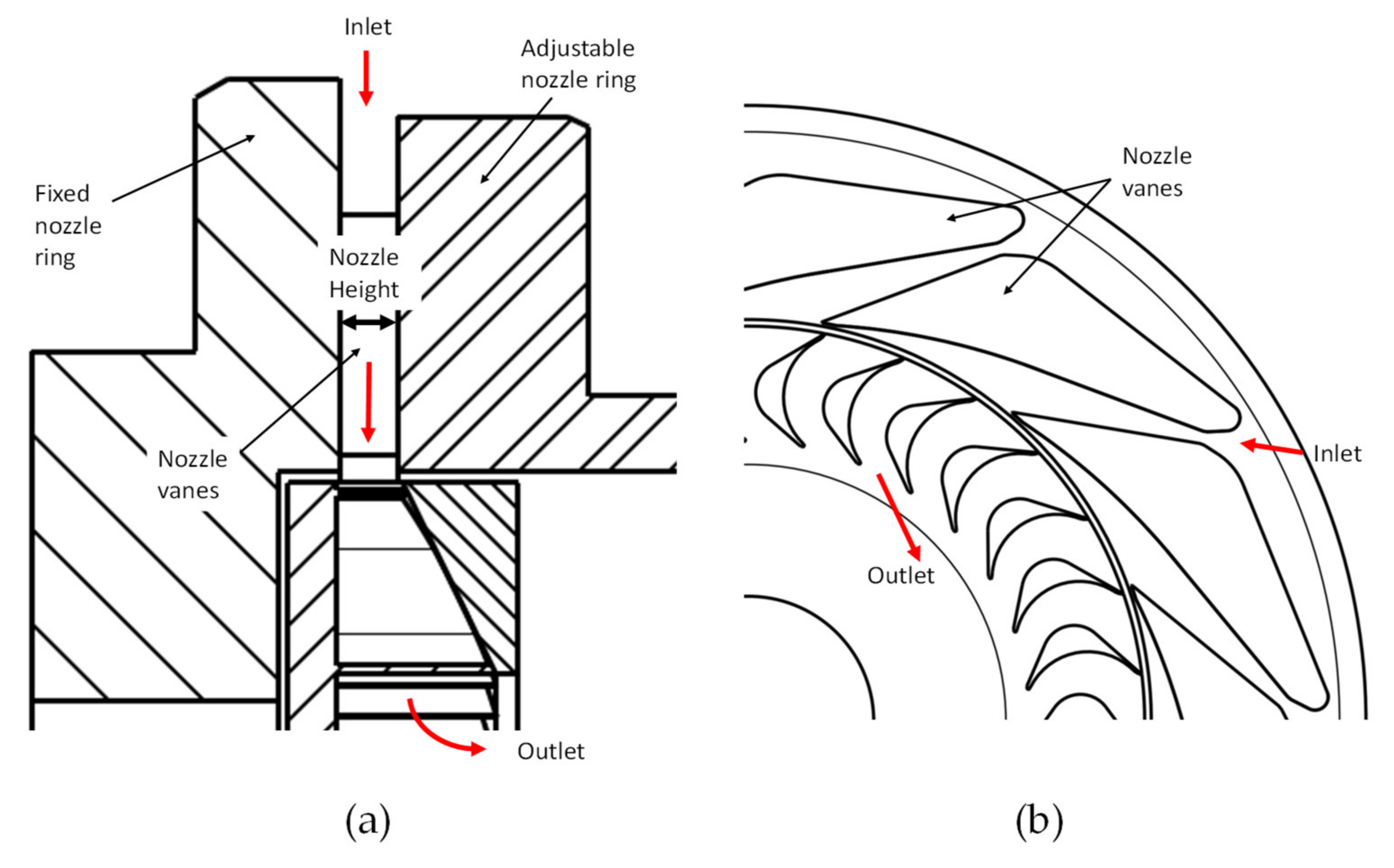
2.2. ANH Concept and Its Implementation

As already described in a previous publication [27], different technologies for adjusting the swallowing capacity of a supersonic turbine were considered by the authors. The adjustable nozzle height (ANH) concept, which is similar to the concept of Rogo et al. [25,26], was the most promising technology. Since only the ANH holds the possibility of adjusting the nozzle throat area while maintaining a constant area ratio of the nozzles, this approach has been elaborated. By moving the sidewall of the nozzle ring, the flow area in the turbine is adjusted to the available mass flow rate (see Figure 1a). Due to this arrangement, the nozzle area ratio and therefore the nozzle outlet velocity stays constant (assuming a proper control of the height in respect to the available mass flow rate).
The simultaneous change of the throat and outlet area of the nozzles is implemented by adjusting the nozzle height. Thus, the area ratio of the convergent–divergent nozzles (see Figure 1b) is kept constant. The adjustable nozzle ring is moved against plate springs by the fluid pressure. Hence, there is no need for additional electronical parts such as a stepper motor to control the nozzle position. If the mass flow rate is reduced, the inlet pressure of a turbine with a fixed nozzle will decrease. In the case of the ANH, the springs move the adjustable nozzle ring and close the nozzle to adjust the inlet pressure. A certain pressure variation around the design pressure must be accepted. The thermodynamic boundary conditions for the turbine at design point are equal to the Cantilever turbine, which has already been discussed in previous publications of the authors [28,29]. However, the nozzle design was slightly modified so that the nozzles change their area in one dimension, instead of two dimensions in the previous construction. In the present paper, the following turbine configurations are considered:

2.2.1. Fixed ANH Turbine (F-ANH)

This configuration serves as a reference case. Using a clamping construction, the movement of the sidewall of the nozzle is blocked and held constant at 100% height, which corresponds to the design point of a standard Cantilever turbine. Thus, the ORC test rig operates at sliding pressure.

2.2.2. Manually Adjusted Turbine Geometry (M-ANH)

In this configuration, the nozzle height is changed by using distance blocks with defined height. The nozzle height percentage always corresponds to the mass flow rate percentage. Through this control strategy, the turbine inlet pressure could theoretically be kept constant for the different mass flow rates. This case can be considered as the ideally controlled nozzle height.

2.2.3. Automatically Adjusted Turbine Geometry (A-ANH)

This configuration represents the technical implementation of the adjustable nozzle height. As already described above, the nozzle travel is realized by plate springs. According to the present mass flow rate, the balance of forces is achieved at different nozzle heights. To realize the travel based on the balance of forces, a certain range of the turbine inlet pressure has to be accepted.

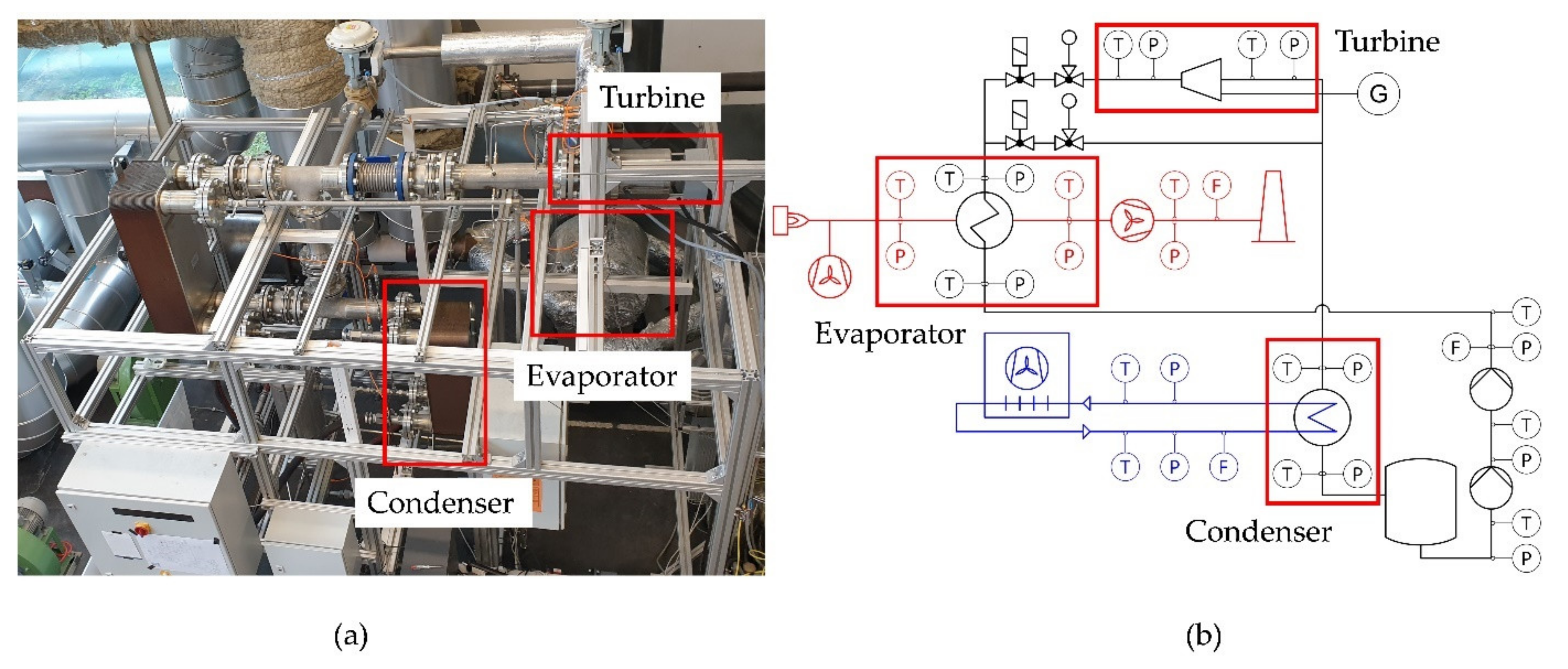
2.3. The ORC Test Rig

As a first application of the adaptive turbine, an ORC test rig located at the University of Bayreuth was chosen. The test rig was built up to simulate an application as a WHR unit. As working fluid, hexamethyldisiloxane (MM) was applied. With this test rig, part-load operating points down to 50% of the design working fluid mass flow rate were considered. Table 1 summarizes the considered operating points for the test rig. Note that the utilized heat flux in the evaporator Q ˙ E G , u t varies due to the application of different turbine configurations and the resulting differences in the working fluid evaporation pressures. Furthermore, this heat flux is influenced by the supply temperature of the pressurized working fluid at the cold side of the evaporator.
In Figure 2, a photograph (a) and P&ID scheme (b) of the test rig are shown. The test rig can be divided into the sections “heat supply” (red), “heat rejection” (blue) and ORC (black).
In Table 2, an overview of the main components of the experimental test rig is given. Since it was designed for waste heat profiles occurring in industry, a propane gas burner was used to simulate the waste heat of the upstream process. For pumping the low-pressure fluid to the required pressure level, two pumps were used. The piston diaphragm pump was reused from a former plant. To fit the boundary conditions of the current plant, an additional centrifugal pump as booster pump is required to avoid cavitation. For preheating, evaporating and superheating, a Plate and Shell heat exchanger from the manufacturer GESMEX was used. For the sake of simplicity, in the following this heat exchanger is referred to as “evaporator”. As expansion machine, the three different configurations shown in the last chapter were considered. Regarding the turbine design data, the authors refer to their previous publications [28,30,31]. The applied high-speed generator was connected to a feed-in unit. Using power electronics, the rotational speed of the turbine could be controlled to the desired value. The generated electrical power was fed into the University grid. The plate heat exchanger serving as condenser was provided by ALPHA LAVAL. An air cooler outside the building was used to cool the intermediate water/glycol cycle which served as the cold supply for the condenser.

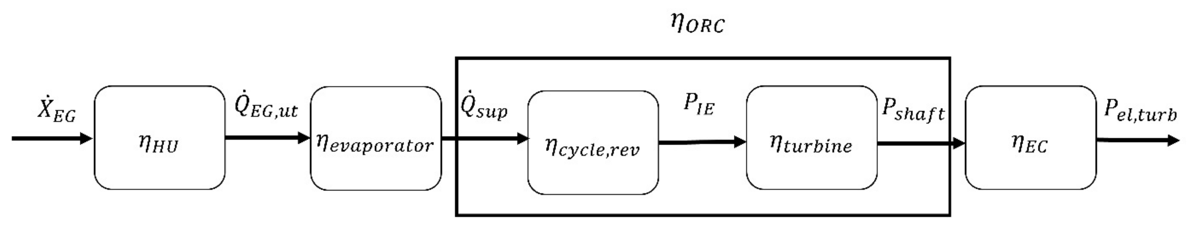
2.4. Energy Conversion Chain and Considered Conversion Steps

To evaluate the influences of the three different turbine configurations on the entire system, the energy conversion chain was analysed, beginning with the available exergy flux of the exhaust gas and ending with the electrical power output of the turbine (see Figure 3). For calculating the thermodynamic properties of the working fluids as well as those of the exhaust gas, the REFPROP Database version 9.1 [32] was used.
Due to the experimental character of the test rig, the results for the different turbine configurations indicated that the reversible cycle efficiency η c y c l e , r e v and turbine efficiency η t u r b i n e were the energy conversion steps mainly influenced by the adaptive turbine. The other conversion steps, particularly the evaporator efficiency, showed a relatively low dependency in the off-design cases. Therefore, the remaining energy conversion steps are not analysed in the present publication.
To calculate the reversible efficiency of the cycle η c y c l e , r e v , the ratio of isentropic expansion power P I E and supplied heat flux Q ˙ s u p must be built.
η c y c l e , r e v = P I E Q ˙ s u p × 100 % = m ˙ O R C × Δ h i s , t u r b i n e H ˙ O R C , E V , o u t H ˙ O R C , E V , i n × 100 %
The turbine efficiency describes the share of thermodynamically available power that is converted into shaft power.
η t u r b i n e = P s h a f t P I E × 100 % = P e l , t u r b i n e η E C m ˙ O R C × Δ h i s , t u r b i n e × 100 %
where P I E is calculated from the mass flow rate of the working fluid m ˙ O R C and the total-to-static isentropic enthalpy drop over the turbine Δ h i s , t u r b i n e .
These two conversion steps mainly determine the overall waste heat recovery efficiency, η W H R .
η W H R = P e l , t u r b X ˙ E G × 100 %
To enable an effective assessment of the different considered technologies, the ORC efficiency η O R C is introduced as follows:
η O R C = η c y c l e , r e v × η t u r b i n e 100 % = P s h a f t Q ˙ s u p × 100 %
Through this parameter, the effect of the various analysed turbines on the efficiency of waste heat recovery can be evaluated.

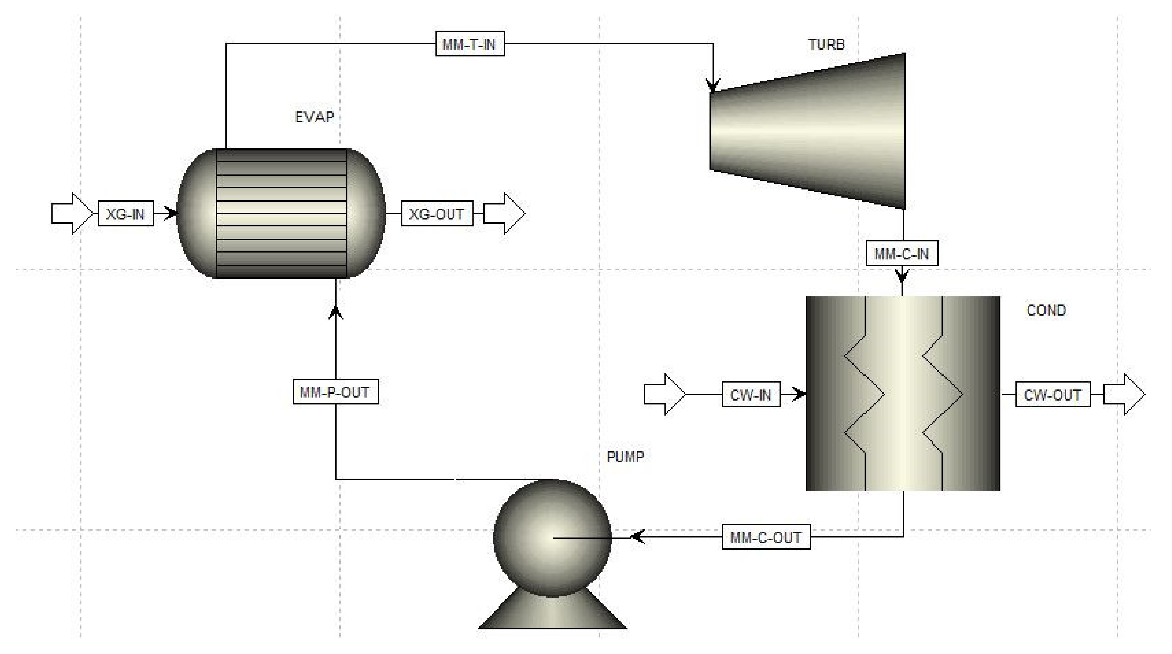
2.5. Semi-Empirical Model as Basis of Performance Evaluation

The turbine outlet pressure is an important influencing variable for the cycle, the turbine and therefore for the whole energy conversion chain. As the measurement campaigns for the different turbine configurations were performed in different seasons and the heat rejection of the test rig was realized by an air cooler, the condensing pressure could not be kept completely constant. To enable a fair comparison of the investigated turbine technologies, a digital twin of the plant was built. This digital twin was based on a semi-empirical simulation model and has already been presented in a previous publication of the authors [33].
Figure 4 shows the main flow sheet of the simulation model. For the evaporator (EVAP), a power law approach was adjusted to the present heat transfer problem and applied. The condenser was simulated based on an empirical model derived from experimental series. Pressure losses were not included in the simulation model. The digital twin was based on the mathematical data fits (polynomial functions of the first and second degree) of the experimental results. To calculate the fluid properties, the Peng–Robinson equation of state was applied. To model the experimental data fits, different design specifications depending on the working fluid mass flow rate (percentage) were integrated into the simulation. The following input parameters were considered in the simulation to approximate the measured plant behaviour:
  • Exhaust gas (XG-IN) composition (CO2, H2O, N2, O2)
  • Exhaust gas mass flow rate
  • Exhaust gas inlet temperature (XG-IN)
  • Efficiency of the pumps (simulated as a single pump)
  • Thermal capacity ( U × A ) values, approximated by a power law approach for the evaporator (EVAP)
  • Constant turbine inlet temperature of 190 °C (independent of mass flow rate)
  • Efficiency of the turbine
  • Condenser (COND) efficiency (by implementing a certain heat leakage)
  • Degrees of subcooling of the working fluid (MM-C-OUT) in the condenser
  • Cooling water inlet temperature (CW-IN)
For the developed adaptive turbine, the existing model implemented the corresponding experimental data and characteristics. As described in [33] for a turbine with constant geometry, the turbine efficiency is a function of turbine pressure ratio and almost independent of the working fluid mass flow rate. However, for a specified geometry of an adaptive geometry turbine, the turbine efficiency depends on the turbine pressure ratio and the corrected mass flow rate.
To derive the turbine efficiency characteristics at various outlet pressures, the experimental data were interpolated by the thin plate spline (TPS) method (see Figure 5). This method was chosen for two reasons: first, as a radial basis function TPS enables the unique solvability of the multidimensional interpolation. Second, the assumption of a minimum curvature of the surface matches the expected course of the graph. In Figure 5, the turbine efficiency characteristics for the A-ANH configuration are shown in dependency on the mass flow rate percentage and turbine outlet pressure (≈condensing pressure). The blue cubes represent the measured operating points, while the green spheres show the interpolated values (by means of the TPS method) for three different considered turbine outlet pressures. In the following, three different condensing pressures (0.35 bar, 0.40 bar, 0.45 bar) were considered for comparison of the investigated turbine configurations (F-ANH, M-ANH, A-ANH).
Subsequent to TPS interpolation, the resulting values for the different outlet pressures were fitted by second order polynomial fitting. Hence, for each turbine configuration and for each outlet pressure, a turbine efficiency characteristic in dependency on the working fluid mass flow rate was derived, which was then used for the calculations with the digital twin. Figure 6 shows, exemplarily for the A-ANH configuration, the derived polynomial fits for the turbine efficiency in dependency on the mass flow rate percentage for the three considered turbine outlet pressures. These fits of second order were fed into the simulation model.

3. Results and Discussion

In this section, the main findings from the experimental investigations as well as those of the simulative analysis are summarized.

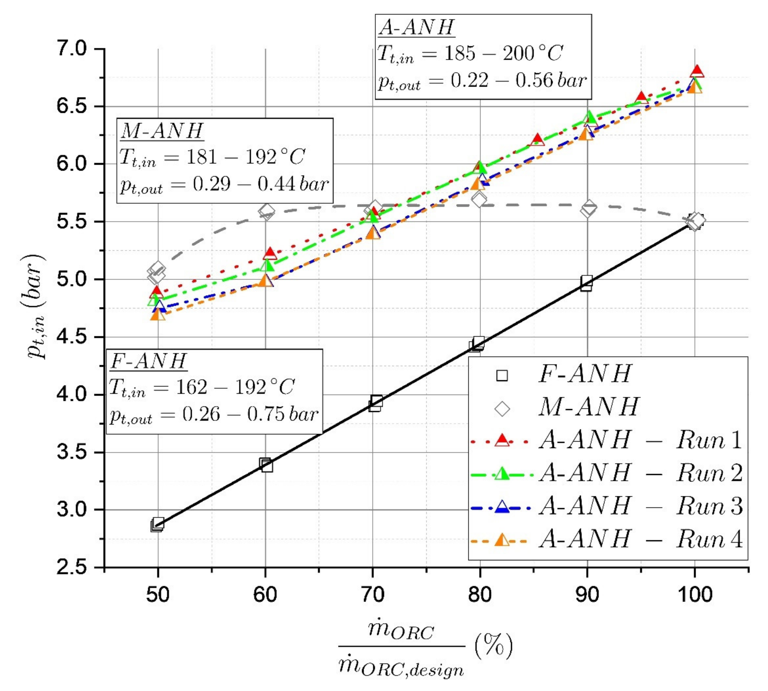
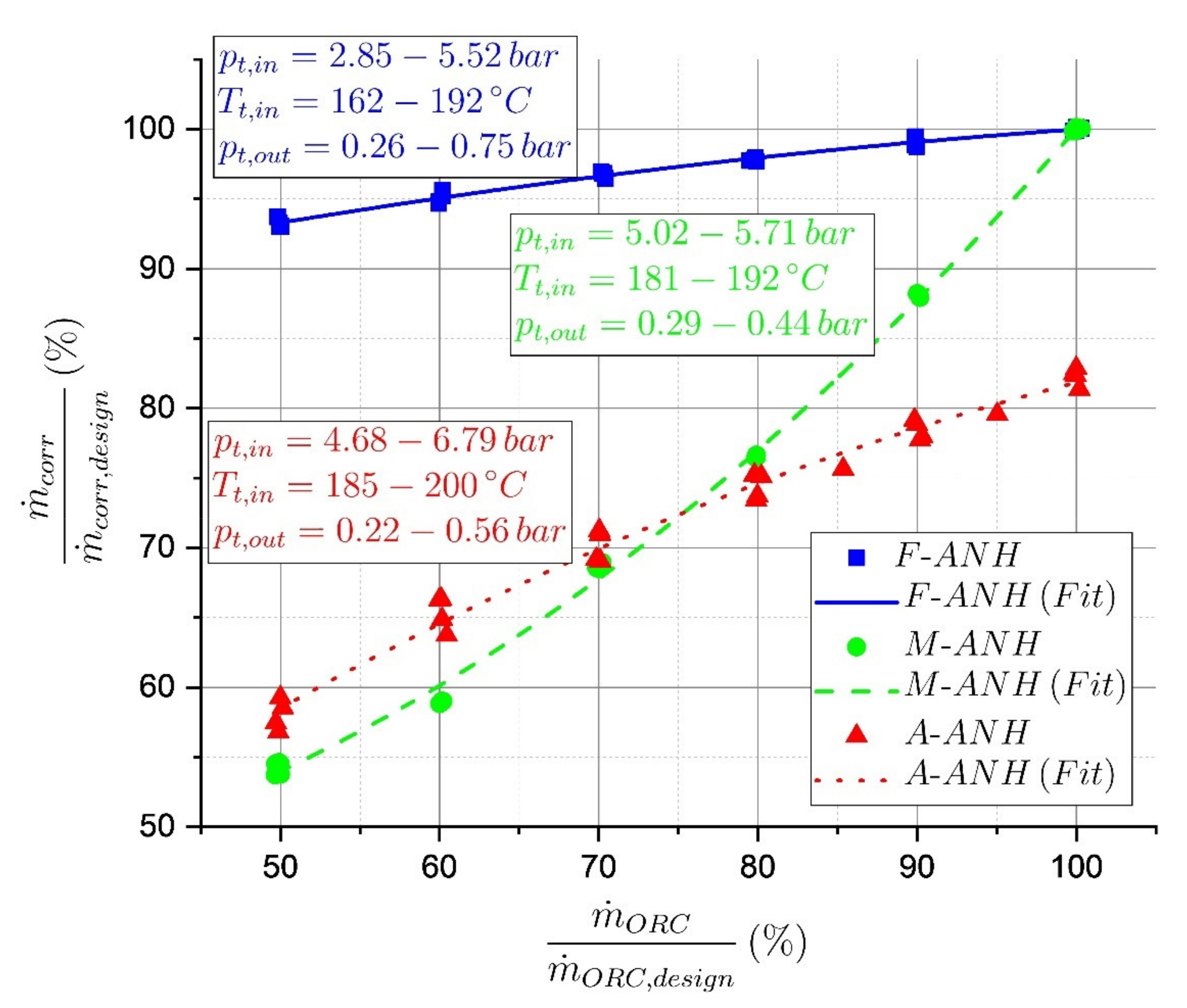
3.1. Swallowing Capacity and Turbine Inlet Pressure

In Figure 7, the experimental results are shown for the corrected mass flow rate (see Equation (5)), normalized by its design value and in dependency on the working fluid mass flow rate. For the fixed geometry turbine (F-ANH), the swallowing capacity is almost constant. The slight reduction in decreasing mass flow rates can be explained by a real gas behaviour. For the M-ANH turbine configuration, the nozzle height percentage always corresponds to the mass flow rate percentage (50% nozzle height corresponds to 50% mass flow rate, etc.). The resulting swallowing capacity behaviour matches expectations in that the share of the swallowing capacity is very similar to the share of the mass flow rate due to the adjustment of the nozzle geometry. In the case of the A-ANH curve, an interesting behaviour is obtained. In low part-load operation, the A-ANH shows a higher swallowing capacity than the ideal adjustment (M-ANH). At approximately 72% mass flow rate, the F-ANH and the M-ANH graphs intersect. Moving towards higher mass flow rates, the automatically adjusted turbine shows a significantly lower swallowing capacity, and only achieves approximately 81% of the design value.
As a consequence of the swallowing capacity adjustment, the turbine inlet pressure is also influenced. Figure 8 depicts the turbine inlet pressure in dependency on the working fluid mass flow rate for the considered turbine configurations. For the F-ANH curve, the theoretically expected behaviour of a sliding inlet pressure can be confirmed. For the M-ANH configuration, the turbine inlet pressure stays almost constant for the considered mass flow rate range. This is due to the manual adjustment of the nozzle area and correspondingly of the swallowing capacity, as shown in the previous diagram. An exception to this behaviour represents the operating point at 50% mass flow rate. Here, a significant drop in the turbine inlet pressure to approximately 5.0 bar is observed. This can be explained by an increasing leakage flow through the adjustable geometry at low nozzle heights. Due to the fact that the travel of the nozzle height is at the A-ANH configuration implemented by a balance of forces, a perfectly constant turbine inlet pressure is excluded by principle. Hence, a certain pressure glide, and thus a deviation from the M-ANH behaviour, has to be accepted for the A-ANH configuration. In Figure 8, four different runs for the A-ANH configuration are shown. The turbine inlet pressure increases from approximately 4.75 to 6.75 bar in the considered mass flow rate range. It becomes obvious that the course of the graph could not exactly be reproduced for the four runs. This can be explained by the sensitivity of the balance of forces on various influencing factors. In particular, the turbine outlet pressure, which varied for the different runs, is expected to influence the balance of forces and therefore the travel of the nozzle. Nevertheless, the prototype A-ANH turbine showed the feasibility of the approach as well as reproducibility regarding its qualitative behaviour.

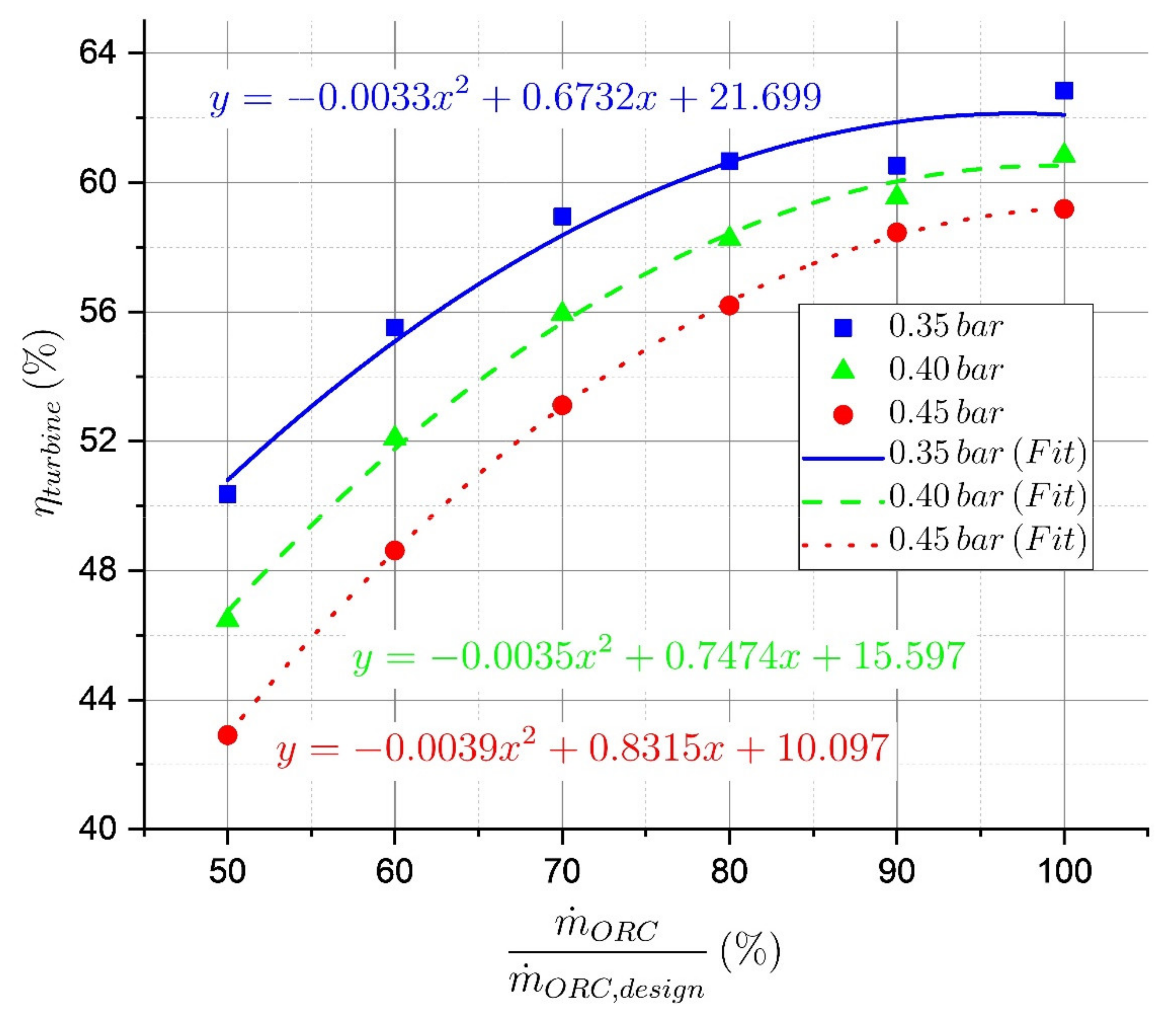
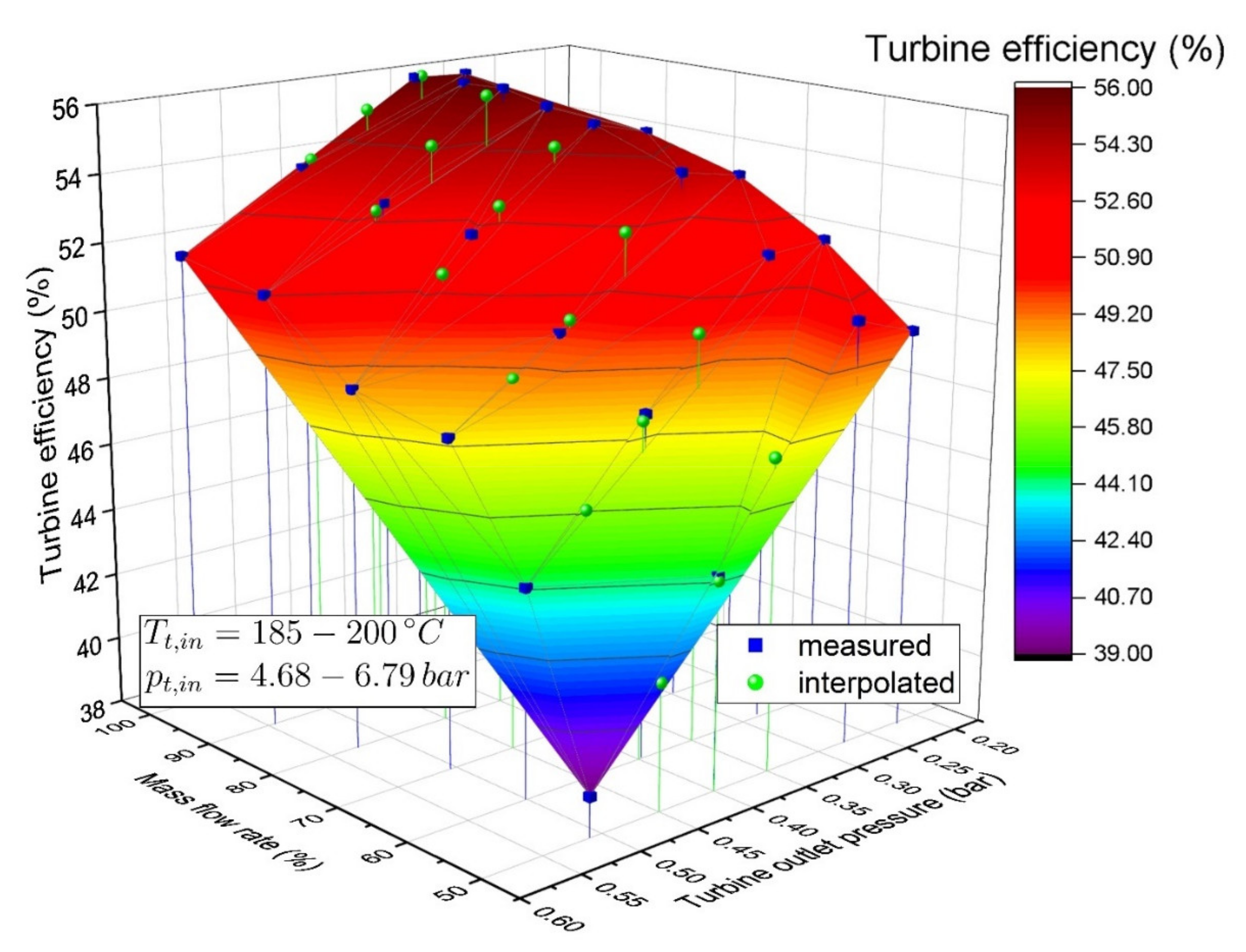
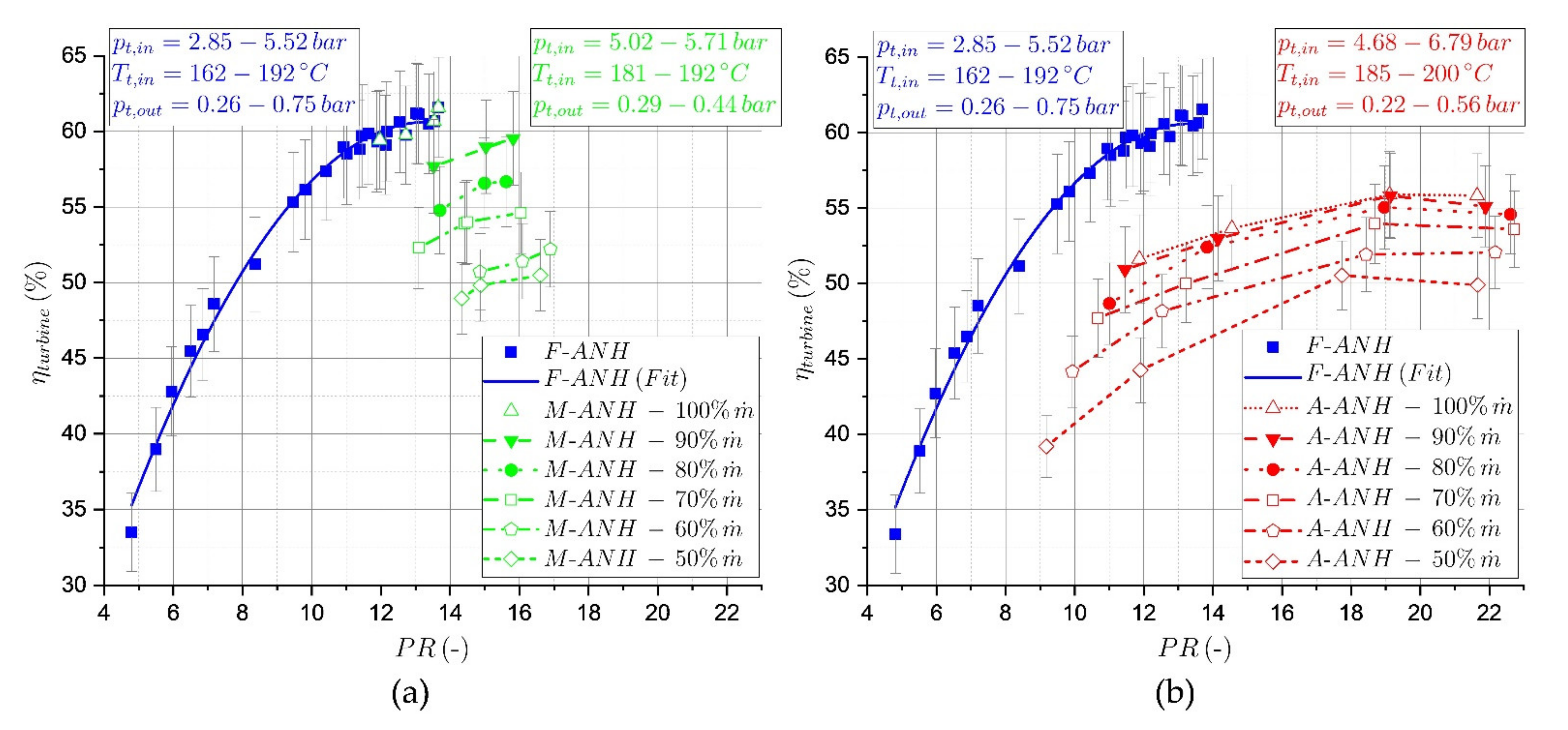
3.2. Turbine Efficiency for the Different Turbine Configurations

When it comes to the energy yield of a WHR plant, the total-to-static isentropic turbine efficiency is one of the most important parameters. The previously shown results indicate that the turbine is able to adjust to the available working fluid mass flow rate. This adjustment has a strong influence on turbine efficiency, which is shown in Figure 9. In this figure, the experimental results for the turbine efficiency of the three turbine configurations in dependency on the pressure ratio are shown for M-ANH and A-ANH; each mass flow rate corresponds to an own nozzle height and therefore to efficiency characteristics. Hence, for these two configurations the corresponding mass flow rate for the shown graphs is given in the diagrams.
The F-ANH graph derives from measurements with 50 to 100% mass flow rate at different turbine outlet pressures. It shows a similar behaviour to that already observed in previous publications of the authors [33]. However, due to the changed construction for swallowing capacity adjustment, the efficiency level is lowered as a result of leakage flows through the nozzle ring. As this is the first turbine of its kind, the leakage flows are expected to be reduced as the technology becomes more mature and the size of the turbine increases. For the M-ANH and the A-ANH graphs, the F-ANH characteristic serves as a benchmark. A decrease in mass flow rate for M-ANH and A-ANH is associated with a significantly decreasing level of turbine efficiency, even at the same pressure ratio. For a decreasing mass flow rate, the nozzle height is reduced (manually or automatically) and the difference between the channel height of the nozzle and channel height of the rotor increases. The resulting step in the flow path leads to a significant rise of dissipated work. This pronounced behaviour was unexpected by the authors, as in a previous publication [27] both the simulation and the experimental results for a supersonic air turbine indicated only a slight efficiency decrease at 50% nozzle height.
The efficiency level of the A-ANH curves is, for higher mass flow rates, significantly lower than that of the M-ANH graphs at the same mass flow rate. This circumstance may be explained in conjunction with Figure 7; as the A-ANH graph shows a lower swallowing capacity for higher mass flow rates, the nozzle height for these operating points is lower than that of the M-ANH configurations. Hence, the step in the stream path is higher, and therefore also created dissipation.
For the experimental data shown in Figure 9, an error calculation was performed in [34]. The errors of the total-to-static isentropic turbine efficiency were calculated by applying the Gaussian law of error propagation. As it would exceed the scope of the present paper, a detailed description is not provided here. However, the same approach as that presented in [35] was followed. Based on the accuracies shown in Table 3, the Gaussian law of error propagation was applied in order to derive the shown error bars in Figure 9. The power is taken from an internal measurement of the feed-in unit. As no data for the accuracy of this measurement were available, the power measurement was regarded as free of errors. The error resulting from the application of REFPROP was also handled as in [35]. In addition to the errors resulting from the applied sensors, the errors from the signal conditioning units were included in the error calculation for turbine efficiency. In Table 4, the accuracies of the corresponding modules are summarized. Note that Module NI 9207 was applied for the pressure sensors, while NI 9208 was used for the mass flow rate measurement. The final resulting errors for turbine efficiency lie in the range of 2 to 3.3 percentage points.
Because a direct comparison of the M-ANH and A-ANH with the benchmark is not possible due to differing turbine outlet pressures during the measurements, a more detailed description of the experimentally determined efficiency graphs is not provided here. However, in the following section, a fair comparison of simulated results at equal outlet pressures is provided.

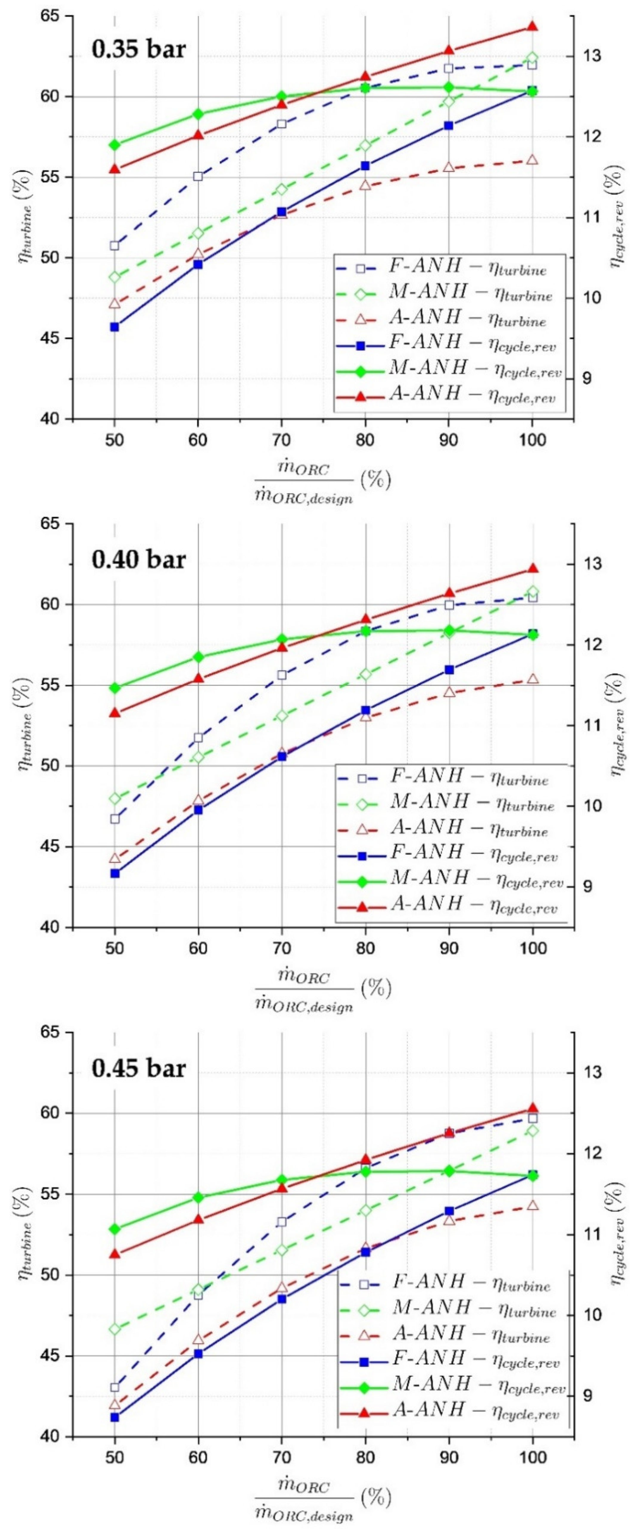
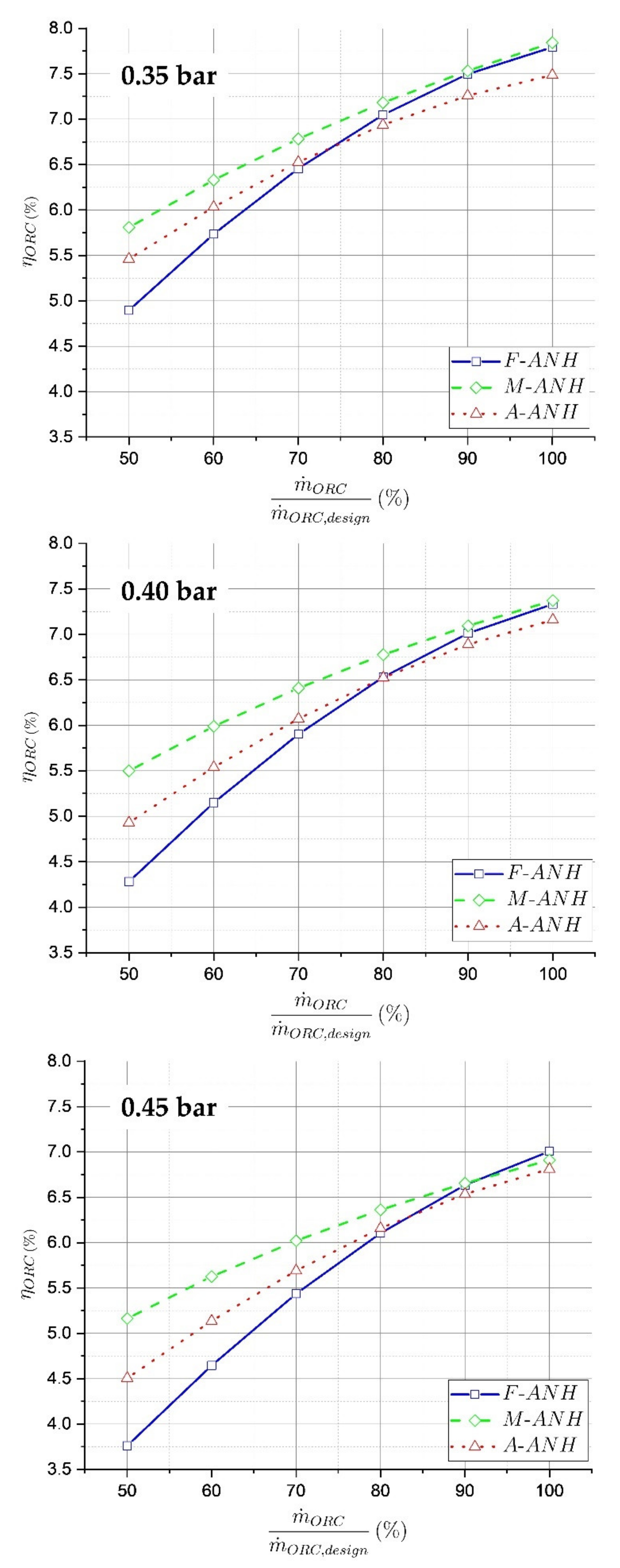
3.3. Turbine Efficiency, Reversible Cycle Efficiency and ORC Efficiency Calculated with the Digital Twin

As already described in Section 3.2, the turbine efficiency characteristics for the M-ANH as well as the A-ANH are at part-load negatively affected by the adjustment of the nozzle height (see Figure 10). Hence, at these conditions there is a turbine efficiency reduction with respect to the F-ANH results. In the case of the M-ANH configuration, the highest reduction of turbine efficiency, approximately four percentage points, appears at 70% mass flow rate and 0.35 bar outlet pressure. For the A-ANH, a reduction of up to 6.2 percentage points compared to the benchmark can be observed at 90% mass flow rate and at 0.35 bar outlet pressure. From the simulated results in Figure 10 it becomes obvious that the reduction of turbine efficiency when applying the adaptive geometries is less pronounced at higher turbine outlet pressures (0.40 and 0.45 bar). Interestingly, the turbine efficiency in part-load for the M-ANH graph is, for higher turbine outlet pressures, higher than that of the F-ANH. For instance, at 50% part-load and 0.45 bar outlet pressure, the turbine efficiency is 3.6 percentage points higher than the benchmark. Here, the positive effect of the higher turbine inlet pressure on the pressure ratio overcompensates for the losses created by the step in the flow path.
Generally, a deterioration in the turbine efficiency due to the application of an adjustable geometry was expected and confirmed by the investigations in the present publication. In addition to the negative effect on the turbine efficiency, a positive influence on the reversible cycle efficiency, especially at part-load, can be observed for the adjustable geometry configurations. The ideally adjusted M-ANH configuration shows the best part-load characteristic concerning cycle efficiency. Concerning the M-ANH graph at 0.45 bar outlet pressure, the highest increase in cycle efficiency, from 8.7 to 11.1%, can be observed. While the A-ANH shows the highest cycle efficiency for all considered turbine outlet pressures at the higher mass flow rates (max. 13.4% at 100% mass flow rate and 0.35 bar outlet pressure), it decreases in part-load below the efficiency of the M-ANH graph. This behaviour can be directly attributed to the observed turbine inlet pressure characteristics in Figure 8. A higher turbine inlet pressure is associated with a higher reversible cycle efficiency, and vice versa. However, at 0.45 bar outlet pressure the A-ANH achieves a significant improvement in cycle efficiency, from 8.7 to 10.8%. Overall, with both adjustable configurations (M-ANH and A-ANH) the cycle efficiency is higher than that of the fixed geometry turbines for all mass flow rates and turbine outlet pressures.
The overarching goal of the authors was to increase the energy yield of the ORC unit in part-load by the application of the adaptive turbine. Due to an oversizing of the evaporator of the considered ORC test rig, the evaporator off-design characteristics barely influenced energy conversion in our case. Referring to the energy conversion chain presented in the materials and methods section, the heat utilization rate and the evaporator efficiency were therefore barely affected by the application of the different turbine configurations, which is why those results are not shown in the present paper. However, for a properly designed evaporator, a significant effect on energy yield from its part-load performance can be expected. The efficiency of the electrical chain only depends on the resulting electrical power, and is therefore not influenced by the applied turbine. Thus, the cycle efficiency and the total-to-static isentropic turbine efficiency are the two energy conversion steps which mainly determine the energy yield of the ORC unit. By introducing a turbine with adjustable swallowing capacity, two opposing effects on the part-load operation of the unit result: the turbine efficiency decreases due to leakages and a step in the flow path of the working fluid, while the reversible cycle efficiency increases as a result of the higher turbine inlet, i.e., upper cycle pressure. To evaluate the overall result of these opposing effects, the ORC efficiency, η O R C must be calculated. Figure 11 shows η O R C for the three considered turbine outlet pressures. As intended, by applying the adjustable geometry turbines (M-ANH and A-ANH) an improved η O R C in part-load can be achieved for all outlet pressures. Hence, the increased reversible cycle efficiency with the adaptive turbines overcompensates for the decrease in turbine efficiency. The efficiency with the manually adjusted geometry exceeds for all considered operating points that of the automatically adjusted one. The highest improvement in ORC efficiency, from 3.8 to 5.2%, can be observed for the M-ANH configuration at 0.45 bar outlet pressure and 50% mass flow rate. At the same operating point, the A-ANH achieves a η O R C of 4.5%. The improvement of the ORC efficiency at 0.35 outlet pressure and 50% mass flow rate is less pronounced, but still significant. With the M-ANH, it is increased by 0.9 percentage points, while the application of the A-ANH delivers an improvement of η O R C by 0.6 percentage points. From Figure 11 it becomes obvious that the mass flow rate, where the A-ANH efficiency exceeds the efficiency with the fixed geometry turbine, increases with higher turbine outlet pressure. While the mentioned mass flow rate corresponds to 73.6% at 0.35 bar outlet pressure, it shifts to 83.2% at 0.45 bar outlet pressure. Thus, the A-ANH configuration shows an improved energy yield (with respect to the benchmark) for low mass flow rates and for outlet pressures higher than design.

4. Conclusions

In the present paper, three different turbine configurations were applied in an experimental ORC unit: a fixed geometry Cantilever turbine (F-ANH), a manually adjusted turbine geometry (M-AN) and an automatically adjusted turbine geometry (A-ANH). The presented A-ANH technology proved itself as an effective approach to adjust the swallowing capacity to match the available mass flow rate. As a consequence of the adjusted swallowing capacity, the turbine inlet pressure (i.e., upper cycle pressure) in part-load operation could be significantly increased with both the M-ANH and A-ANH. In part-load, due to the decreased channel height of the nozzle ring with respect to the rotor blade height, a significantly decreased turbine efficiency could be derived from the experimental results. As a fair comparison of the three turbine configurations is only possible at both equal mass flow rate and equal turbine outlet (i.e., condensing pressure), a digital twin of the ORC test rig was introduced. The digital twin enabled the comparison of the three turbine technologies with equal boundary conditions. While the turbine efficiency of the adjustable geometries was in general lower than that of the fixed geometry turbines, a contrary behaviour was seen with respect to reversible cycle efficiency. For the A-ANH, the turbine efficiency decreased by a maximum of 6.2 percentage points at 90% mass flow rate and 0.35 bar outlet pressure. However, by applying the automatically adjusted turbine, a significant improvement in cycle efficiency compared to the benchmark F-ANH was seen. The most pronounced increase in cycle efficiency for the A-ANH configuration, from 8.7 to 10.8%, was observed at 50% mass flow rate and 0.45 bar outlet pressure. To evaluate the effect of the adjustable swallowing capacity on the energy yield of the plant, the product of cycle efficiency and turbine efficiency ( η O R C ) was analysed. As intended, the turbine configurations with adjustable geometry showed improved efficiency at the part-load operating points. This behaviour became more pronounced as the turbine outlet pressure increased. The A-ANH achieved an improvement of ORC efficiency from 4.9 to 5.5% at 50% mass flow rate and 0.35 bar outlet pressure. At 0.45 bar outlet pressure and 50% mass flow rate, the A-ANH showed the most pronounced increase of η O R C , by 0.7 percentage points. Finally, the A-ANH turbine, as a technical implementation of a supersonic turbine with adjustable swallowing capacity, was proven to increase the energy yield of a WHR ORC unit by a maximum of 18% in part-load operation. Nevertheless, the extent of the increase is highly dependent on the actual waste heat profile. The improvement of the automatic ANH adjustment technology will be subject to future research work.

Author Contributions

Conceptualization, T.P., A.P.W. and F.H.; methodology, T.P., A.P.W. and F.H.; construction and manufacturing of the turbine prototype, J.W. and R.S.; simulation, T.P. and T.W.; investigation, T.P. and A.P.W.; data curation, T.P.; writing—original draft preparation, T.P.; writing—review and editing, T.P., A.P.W., F.H. and D.B.; visualization, T.P.; supervision, A.P.W. and D.B.; project administration, A.P.W.; funding acquisition, A.P.W., F.H. and D.B. All authors have read and agreed to the published version of the manuscript.

Funding

This research was funded by the Bavarian Research Foundation (BFS), under the project “TurboSmart—adaptive Mikroexpansionsturbine für die Energierückgewinnung” (grant number AZ-1344-18). Funded by the Deutsche Forschungsgemeinschaft (DFG, German Research Foundation)—491183248. Funded by the Open Access Publishing Fund of the University of Bayreuth.

Data Availability Statement

The data presented in this study are available on request from the corresponding author.

Acknowledgments

The authors would like to thank Markus Görl and Michael Hickethier for technical support throughout the project and Jan Mišák for his support regarding the error calculation for the turbine efficiency.

Conflicts of Interest

The authors declare no conflict of interest.

Nomenclature

A area(m2)
H ˙ enthalpy flux(J/s)
h specific enthalpy(J/s)
κ isentropic exponent (-)
M Mach number (-)
m ˙ mass flow rate(kg/s)
η efficiency(%)
P power(W)
p pressure(Pa)
P R pressure ratio(%)
Q ˙ heat flux(W)
R i specific gas constant(J/kg/K)
T temperature(K)
U · A thermal capacity(W/K)
X ˙ exergy flux (J/s)
Subscripts
corrcorrected
ECelectrical chain
EGexhaust gas
EVevaporator
elelectric
HUheat utilization
IEisentropic expansion
isisentropic
ORCorganic Rankine cycle
revreversible
ststatic
supsupplied
ttotal
ututilized
WHRwaste heat recovery
Abbreviations
ANHadjustable nozzle height
EAFelectric arc furnace
EVend value
MVmeasured value
PCMphase change material
VTGvariable turbine geometry
WHRwaste heat recovery

References

  1. Pili, R.; Martínez, L.G.; Wieland, C.; Spliethoff, H. Techno-economic potential of waste heat recovery from German energy-intensive industry with Organic Rankine Cycle technology. Renew. Sustain. Energy Rev. 2020, 134, 110324. [Google Scholar] [CrossRef]
  2. Jiménez-Arreola, M.; Pili, R.; Wieland, C.; Romagnoli, A. Analysis and comparison of dynamic behavior of heat exchangers for direct evaporation in ORC waste heat recovery applications from fluctuating sources. Appl. Energy 2018, 216, 724–740. [Google Scholar] [CrossRef]
  3. Pili, R.; Romagnoli, A.; Spliethoff, H.; Wieland, C. Techno-Economic Analysis of Waste Heat Recovery with ORC from Fluctuating Industrial Sources. Energy Procedia 2017, 129, 503–510. [Google Scholar] [CrossRef]
  4. Nardin, G.; Meneghetti, A.; Magro, F.D.; Benedetti, N. PCM-based energy recovery from electric arc furnaces. Appl. Energy 2014, 136, 947–955. [Google Scholar] [CrossRef]
  5. Lecompte, S.; Oyewunmi, O.A.; Markides, C.N.; Lazova, M.; Kaya, A.; Broek, M.V.D.; De Paepe, M. Case Study of an Organic Rankine Cycle (ORC) for Waste Heat Recovery from an Electric Arc Furnace (EAF). Energies 2017, 10, 649. [Google Scholar] [CrossRef]
  6. Bause, T.; Campana, F.; Filippini, L.; Foresti, A.; Monti, N.; Pelz, T. Cogeneration with ORC at Elbe-Stahlwerke Feralpi EAF Shop. In Proceedings of the Iron & Steel Technology Conference and Exposition, Indianapolis, IN, USA, 5–8 May 2014. [Google Scholar]
  7. Ramirez, M.; Epelde, M.; de Arteche, M.G.; Panizza, A.; Hammerschmid, A.; Baresi, M.; Monti, N. Performance evaluation of an ORC unit integrated to a waste heat recovery system in a steel mill. Energy Procedia 2017, 129, 535–542. [Google Scholar] [CrossRef] [Green Version]
  8. Pantaleo, A.M.; Fordham, J.; Oyewunmi, O.; De Palma, P.; Markides, C.N. Integrating cogeneration and intermittent waste-heat recovery in food processing: Microturbines vs. ORC systems in the coffee roasting industry. Appl. Energy 2018, 225, 782–796. [Google Scholar] [CrossRef]
  9. Campana, F.; Bianchi, M.; Branchini, L.; De Pascale, A.; Peretto, A.; Baresi, M.; Fermi, A.; Rossetti, N.; Vescovo, R. ORC waste heat recovery in European energy intensive industries: Energy and GHG savings. Energy Convers. Manag. 2013, 76, 244–252. [Google Scholar] [CrossRef]
  10. Peris, B.; Navarro-Esbrí, J.; Moles, F.; Mota-Babiloni, A. Experimental study of an ORC (organic Rankine cycle) for low grade waste heat recovery in a ceramic industry. Energy 2015, 85, 534–542. [Google Scholar] [CrossRef]
  11. Arreola, M.J.; Pili, R.; Magro, F.D.; Wieland, C.; Rajoo, S.; Romagnoli, A. Thermal power fluctuations in waste heat to power systems: An overview on the challenges and current solutions. Appl. Therm. Eng. 2018, 134, 576–584. [Google Scholar] [CrossRef]
  12. König-Haagen, A.; Höhlein, S.; Brüggemann, D. Detailed exergetic analysis of a packed bed thermal energy storage unit in combination with an Organic Rankine Cycle. Appl. Therm. Eng. 2020, 165, 114583. [Google Scholar] [CrossRef]
  13. Schuster, S.; Markides, C.; White, A.J. Design and off-design optimisation of an organic Rankine cycle (ORC) system with an integrated radial turbine model. Appl. Therm. Eng. 2020, 174, 115192. [Google Scholar] [CrossRef]
  14. Hu, D.; Zheng, Y.; Wu, Y.; Li, S.; Dai, Y. Off-design performance comparison of an organic Rankine cycle under different control strategies. Appl. Energy 2015, 156, 268–279. [Google Scholar] [CrossRef]
  15. Manente, G.; Toffolo, A.; Lazzaretto, A.; Paci, M. An Organic Rankine Cycle off-design model for the search of the optimal control strategy. Energy 2013, 58, 97–106. [Google Scholar] [CrossRef]
  16. Feneley, A.J.; Pesiridis, A.; Andwari, A.M. Variable Geometry Turbocharger Technologies for Exhaust Energy Recovery and Boosting—A Review. Renew. Sustain. Energy Rev. 2017, 71, 959–975. [Google Scholar] [CrossRef]
  17. Kozak, D.; Mazuro, P.; Teodorczyk, A. Numerical Simulation of Two-Stage Variable Geometry Turbine. Energies 2021, 14, 5349. [Google Scholar] [CrossRef]
  18. Moustapha, H.; Zelesky, M.F.; Baines, N.C.; Japikse, D. Axial and Radial Turbines; Concepts ETI, Inc.: White River Junction, VT, USA, 2003; ISBN 9780933283121. [Google Scholar]
  19. Menny, K. Strömungsmaschinen: Hydraulische und Thermische Kraft- und Arbeitsmaschinen, 5th ed.; Teubner: Wiesbaden, Germany, 2011; ISBN 9783519463177. [Google Scholar]
  20. Dick, E. Fundamentals of Turbomachines; Springer: Dordrecht, The Netherlands, 2015; ISBN 978-94-017-9626-2. [Google Scholar]
  21. Stojkovski, F.; Lazarevikj, M.; Markov, Z.; Iliev, I.; Dahlhaug, O. Constraints of Parametrically Defined Guide Vanes for a High-Head Francis Turbine. Energies 2021, 14, 2667. [Google Scholar] [CrossRef]
  22. Polák, M. A Brief History of the Kaplan Turbine Invention. Energies 2021, 14, 6211. [Google Scholar] [CrossRef]
  23. Pfleiderer, C.; Petermann, H. Strömungsmaschinen, 7th ed.; Springer: Berlin, Germany, 2005; ISBN 9783540221739. [Google Scholar]
  24. Casartelli, D.; Binotti, M.; Silva, P.; Macchi, E.; Roccaro, E.; Passera, T. Power Block Off-design Control Strategies for Indirect Solar ORC Cycles. Energy Procedia 2015, 69, 1220–1230. [Google Scholar] [CrossRef] [Green Version]
  25. Rogo, C.; Hajek, T.; Chen, A.G. Variable Stator Radial Turbine; Nasa Lewis Research Center: Cleveland, OH, USA, 1984. [Google Scholar]
  26. Rogo, C. Variable Area Radial Turbine Fabrication and Test Program; Nasa Lewis Research Center: Cleveland, OH, USA, 1986. [Google Scholar]
  27. Streit, P.; Popp, T.; Winkler, J.; Scharf, R.; Weiβ, A.P. Numerical and experimental investigation of different technologies for adjusting the swallowing capacity of a cantilever ORC turbine. AIP Conf. Proc. 2020, 2323, 070001. [Google Scholar]
  28. Weiß, A.P.; Popp, T.; Müller, J.; Hauer, J.; Brüggemann, D.; Preißinger, M. Experimental characterization and comparison of an axial and a cantilever micro-turbine for small-scale Organic Rankine Cycle. Appl. Therm. Eng. 2018, 140, 235–244. [Google Scholar] [CrossRef]
  29. Weiß, A.P.; Novotný, V.; Popp, T.; Zinn, G.; Kolovratník, M. Customized Small-Scale ORC Turbogenerators—Combining a 1D-Design Tool, a Micro-Turbine-Generator-Construction-Kit and Potentials of 3D-Printing. In Proceedings of the 5th International Seminar on ORC Power Systems (ORC2019), Athens, Greece, 9 September 2019. [Google Scholar]
  30. Weiß, A.; Popp, T.; Zinn, G.; Preißinger, M.; Brüggemann, D. A micro-turbine-generator-construction-kit (MTG-c-kit) for small-scale waste heat recovery ORC-Plants. Energy 2019, 181, 51–55. [Google Scholar] [CrossRef]
  31. Weiß, A.P.; Novotný, V.; Popp, T.; Streit, P.; Špale, J.; Zinn, G.; Kolovratník, M. Customized ORC micro turbo-expanders—From 1D design to modular construction kit and prospects of additive manufacturing. Energy 2020, 209, 118407. [Google Scholar] [CrossRef]
  32. Lemmon, E.W.; Huber, M.L.; McLinden, M.O. NIST Standard Reference Database 23: Reference Fluid Thermodynamic and Transport Properties-REFPROP, Version 9.1. Available online: https://tsapps.nist.gov/publication/get_pdf.cfm?pub_id=912382 (accessed on 12 October 2021).
  33. Popp, T.; Heberle, F.; Weiß, A.P.; Brüggemann, D. Thermodynamic Evaluation of an ORC Test Rig—From Comprehensive Experimental Results to a Simulation Model. In Proceedings of the 6th International Seminar on ORC Power Systems (ORC2021), Munich, Germany, 11–13 October 2021. [Google Scholar]
  34. Mišák, J. Fehlerrechnung für das Messsystem des ORC-Versuchskraftwerks am Zentrum für Energietechnik/Uni Bayreuth und Dessen Optimierung. Masterarbeit; Ostbayerische Technische Hochschule Amberg-Weiden: Amberg, Germany, 2021. (In German) [Google Scholar]
  35. Eyerer, S.; Dawo, F.; Kaindl, J.; Wieland, C.; Spliethoff, H. Experimental investigation of modern ORC working fluids R1224yd(Z) and R1233zd(E) as replacements for R245fa. Appl. Energy 2019, 240, 946–963. [Google Scholar] [CrossRef]
Figure 1. Meridional cut (a) and blade-to-blade cut (b) of the implemented adjustable nozzle height concept.
Energies 15 00025 g001
Figure 2. Photograph (a) and P&ID scheme (b) of the experimental ORC plant at the University of Bayreuth.
Energies 15 00025 g002
Figure 3. Energy conversion chain of the ORC.
Energies 15 00025 g003
Figure 4. Main Flowsheet of the digital twin in ASPEN Plus.
Energies 15 00025 g004
Figure 5. Turbine efficiency (measured and interpolated) of the A-ANH configuration in dependency on the mass flow rate and turbine outlet pressure.
Energies 15 00025 g005
Figure 6. Polynomial fits of the turbine efficiency of the A-ANH configuration in dependency on the mass flow rate percentage for three different turbine outlet pressures.
Energies 15 00025 g006
Figure 7. Normalized corrected mass flow rate (swallowing capacity) as a function of the working fluid mass flow rate.
Energies 15 00025 g007
Figure 8. Turbine inlet pressure as a function of the working fluid mass flow rate.
Energies 15 00025 g008
Figure 9. Total-to-static isentropic turbine efficiency for F-ANH and M-ANH (a) and for F-ANH and A-ANH (b) as a function of the pressure ratio (PR).
Energies 15 00025 g009
Figure 10. Total-to-static isentropic turbine efficiency and reversible cycle efficiency in dependency on the working fluid mass flow rate, calculated by the digital twin for 0.35, 0.40 and 0.45 bar turbine outlet pressure.
Energies 15 00025 g010
Figure 11. ORC efficiency η O R C in dependency on the working fluid mass flow rate, calculated by the digital twin for 0.35, 0.40 and 0.45 bar turbine outlet pressure.
Energies 15 00025 g011
Table 1. Considered ORC operating points.
m ˙ O R C m ˙ O R C , d e s i g n m ˙ O R C Q ˙ E G , u t P e l , d e s i g n
(%)(g/s)(kWth)(kWel)
5016090–1024.0
60192106–1165.6
70224125–1337.2
80256139–1508.8
90288160–16810.4
100320178–18412.0
Table 2. Main components of the ORC test rig.
ComponentType
Heat supplyPropane gas burner
PumpsCentrifugal and piston diaphragm pump (both with variable frequency drive)
“Evaporator”Plate and Shell type heat exchanger
ExpanderQuasi-Impulse Cantilever turbine in F-ANH, M-ANH and A-ANH configuration
CondenserPlate heat exchanger
Heat rejectorAir cooler
Table 3. Measuring range and accuracy of sensors for calculating the turbine efficiency.
Measured ParameterTypeMeasuring RangeAccuracy of
Measurement
Turbine inlet temperatureOmega PR-22-3-100-A-M3-150-M12−30–350 °C1 °C
Turbine inlet pressureOmega PAA23SYC-10-M120–10 bar1.5% of EV
Turbine outlet pressureOmega PAA23SY C-2-M120–2 bar1.5% of EV
Mass flow rateABB CoriolisMaster FCB3300–416,667 g/s0.4% of MV
PowerSieb & Meyer 0362111OF0–20 kWN/A
Table 4. Measuring range and accuracy of the signal conditioning units.
ModuleMeasuring RangeAccuracy of Measurement
NI 92070–22 mA0.87% of MV + 0.05% of EV
NI 92080–22 mA0.76% of MV + 0.04% of EV
Publisher’s Note: MDPI stays neutral with regard to jurisdictional claims in published maps and institutional affiliations.

