Article

Grid-Tied Distribution Static Synchronous Compensator for Power Quality Enhancement Using Combined-Step-Size Real-Coefficient Improved Proportionate Affine Projection Sign Algorithm

by
Arobinda Dash
1,
Durgesh Prasad Bagarty
1,
Prakash Kumar Hota
2,
Manoj Kumar Sahu
3,*,
Twinkle Hazra
3,
Siddhartha Behera
4,
Arun Kumar Behera
3,
Siddharth Behera
3,
Amit Kumar Nayak
3,
Sangram Ballav Mohapatra
3 and
Shreekanta kumar Ojha
5
1
Department of Electrical Engineering, OUTR (Odisha University of Technology and Research), Formerly CET (Formerly College of Engineering & Technology), Bhubaneswar 751029, India
2
Department of Electrical Engineering, VSSUT (Veer Surendra Sai University of Technology), Burla 768018, India
3
Department of Electrical Engineering, CAPGS (Centre for Advanced Post Graduate Studies), BPUT (Biju Patnaik University of Technology), Rourkela 769015, India
4
Department of Electrical Engineering, GITA Autonomous College (An Autonomous College under Biju Patnaik University of Technology), Bhubaneswar 752054, India
5
Department of Electrical Engineering, DRIEMS Polytechnic Institute, Cuttack 754022, India
*
Author to whom correspondence should be addressed.
Energies 2022, 15(1), 197; https://doi.org/10.3390/en15010197
Submission received: 21 November 2021 / Revised: 2 December 2021 / Accepted: 6 December 2021 / Published: 29 December 2021

Abstract

:
A control structure design of a three-phase three-leg four-wire grid-tied Distribution Static Synchronous Compensator (DSTATCOM) based on a combined-step-size real-coefficient improved proportionate affine projection sign algorithm (CSS-RIP-APSA) has been presented. The three-phase four-wire DSTATCOM is used for reactive power compensation along with harmonic current minimization. This strategy also helps in load balancing and neutral current compensation. The affine projection sign algorithm (APSA) is a member of the adaptive filter family, which has a slow convergence rate. The conventional adaptive filter deals with the trade-off between the convergence rate and the steady-state error. In the proposed algorithm, the RIP-APSA adaptive filter with two different step sizes has been designed to decrease the computational burden while achieving the advantages of a fast convergence rate and reduced steady-state error. The proposed controller also makes the inverter function a shunt compensator. The controller primarily evaluates the fundamental weight component of distorted load currents. The aim of the proposed system is to compensate for reactive power and to ensure unity power factor during the faulty conditions as well as for unbalancing grid conditions. The proposed control algorithm of the grid-tied DSTATCOM works effectively on the laboratory prototype as verified from the experimental results.

1. Introduction

The basic function of the Distribution Static Synchronous Compensator (DSTATCOM) is to eliminate the system’s current harmonics and supply the reactive power demand of the load at the fundamental frequency. This makes the utility system supply only the fundamental component current to the load with a unity power factor. This improves the system efficiency. The modern power system becomes adversely affected due to the prominence of unbalanced loading, more use of non-linear loads, and high neutral current due to the third harmonic components. In the low-voltage distribution systems, three-phase four-wire configurations are used for three-phase and single-phase low-voltage loads, such as computer loads, lighting ballasts, a small rating adjustable speed drive in air conditioners, fans, refrigerators, etc. The wide use of single-phase loads in the three-phase system leads to a certain imbalance in the system [1]. These loads produce harmonics in the supply current and cause a large neutral current. It has been observed that the third harmonic components predominate over other harmonic components in a neutral wire during the transient period [2,3,4]. The overloading and overheating in the neutral conductor occurs due to the higher neutral current in comparison with the phase current. This leads to substantial line losses that negatively influence system performance such as the malfunction of sensitive equipment [5] and power-line communication interference [6].
Significant research efforts have been made to solve the issue of minimizing the neutral current. Based on the magnetic configuration, one of the robust and traditional approaches is to employ a star/delta, T-connection, or zigzag connection [7,8]. Some other topologies such as delta-connected solid-state transformers [9], the addition of an extra leg in the inverter, termed as a three-phase four-leg inverter [10], have been used to compensate the neutral current. The issues of overcurrent, active power oscillations, and unexpected voltage sags are the principal concerns with three-phase four-wire inverters under unbalanced grid voltage [11]. However, these topologies not only increase the cost of the system due to the use of additional components but also require advanced control strategies to operate [12,13]. In [14], the operation of DSTATCOM is illustrated dealing with the problem of the zero-sequence components without the need for extra equipment. However, its performance is not satisfactory with dynamic loading conditions and unbalanced grid conditions. However, the power quality issues such as reactive power compensation, grid current balancing with the presence of an unbalanced load, power factor improvement, and maintaining less THD in the grid current with the presence of an unbalanced grid voltage without the use of additional equipment remained unanswered.
The least mean square (LMS) algorithm has a well-known filter that is popular for its simple structure and ease of implementation [15].One of the major drawbacks of the LMS algorithm is its slow convergence rate. Over the last decade, in order to ameliorate the above problem, different researchers have proposed different algorithms such as normalized LMS (NLMS) [16], affine projection algorithm (APA) [17], and affine projection sign algorithm (APSA) [18]. NLMS, and its variants, updates its weight factor based on its single input vector, whereas the variants of the APA family update are based on the adaptive process. That is why the NLMS algorithm has a very poor convergence rate in comparison to others [19]. To improve this, some of the improved filters have been proposed by different authors in different literature by using a proportionate matrix such as proportionate NLMS [20], proportionate APA [21], and real-coefficient proportionate APSA (RP-APSA) [22]. These proportionate filters, having an adaptive step-size, improve the convergence rate but they suffer from large steady-state misalignment. In order to further enhance the performance, improved versions of proportionate filters have been proposed such as improved proportionate APA (IPAPA) [23], improved RP-APSA (RIP-APSA) [22], improved proportionate NLMS [24]. However, these filters still suffer the trade-off between the convergence rate and steady-state error.
The advantage of APSA is that the optimization is based on a larger step-size norm, whereas PNLMS has a proportionate matrix. The combination of the advantages of the above two filters has been applied in the real-coefficient improved proportionate (RIP-APSA) algorithm. It is noticed that the RIP-APSA achieves faster convergence than conventional adaptive filters. However, the computational complexity of this approach is higher than the original APSA [25]. All of the above adaptive filters with a larger step-size give fast convergence and a higher steady-state error. Furthermore, a small step-size provides a small steady-state error but deteriorated convergence rate. To address this issue, [26] proposes a convex combination of two RIP-APSA with different step-sizes, termed CSS-RIP-APSA.
The contributions of the paper are given as follows:
  • Development of the CSS-RIP-APSA control technique for elimination of the third-order harmonic component present in the grid currents under steady-state and transient conditions for a three-phase three-leg four-wire system.
  • The proposed control technique is used for extracting the fundamental and quadrature components from non-linear load currents.
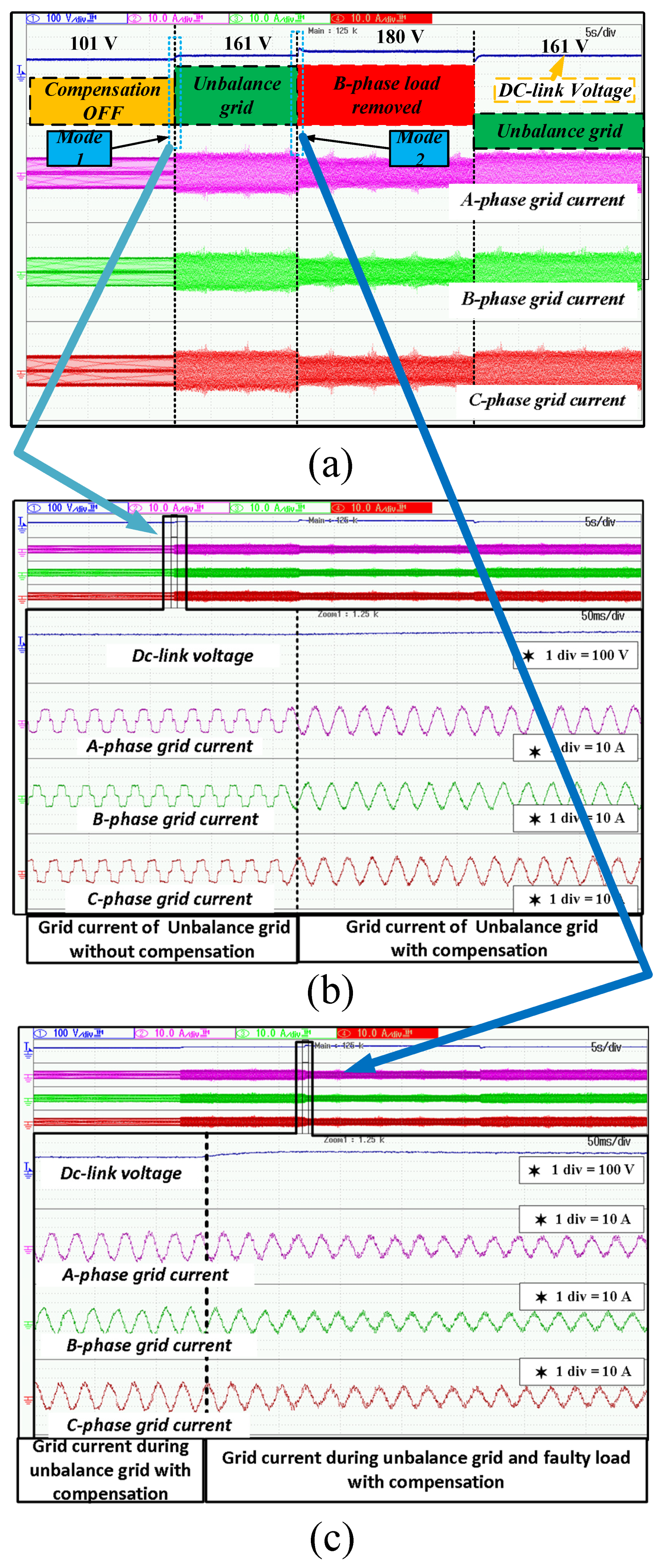
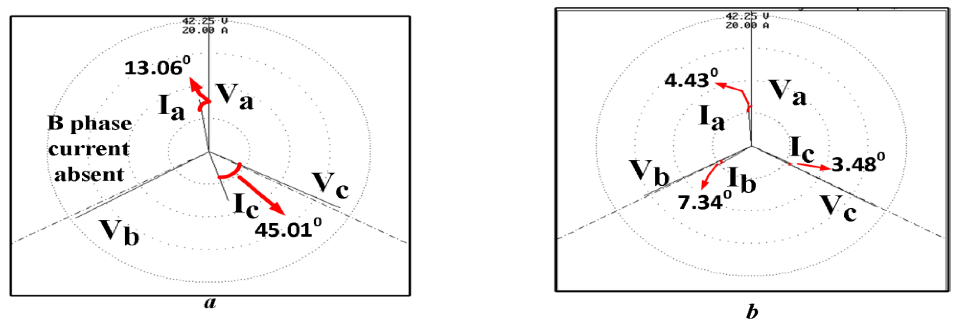
  • The robustness of the controller is examined with the presence of the unbalanced grid voltages and transient conditions.
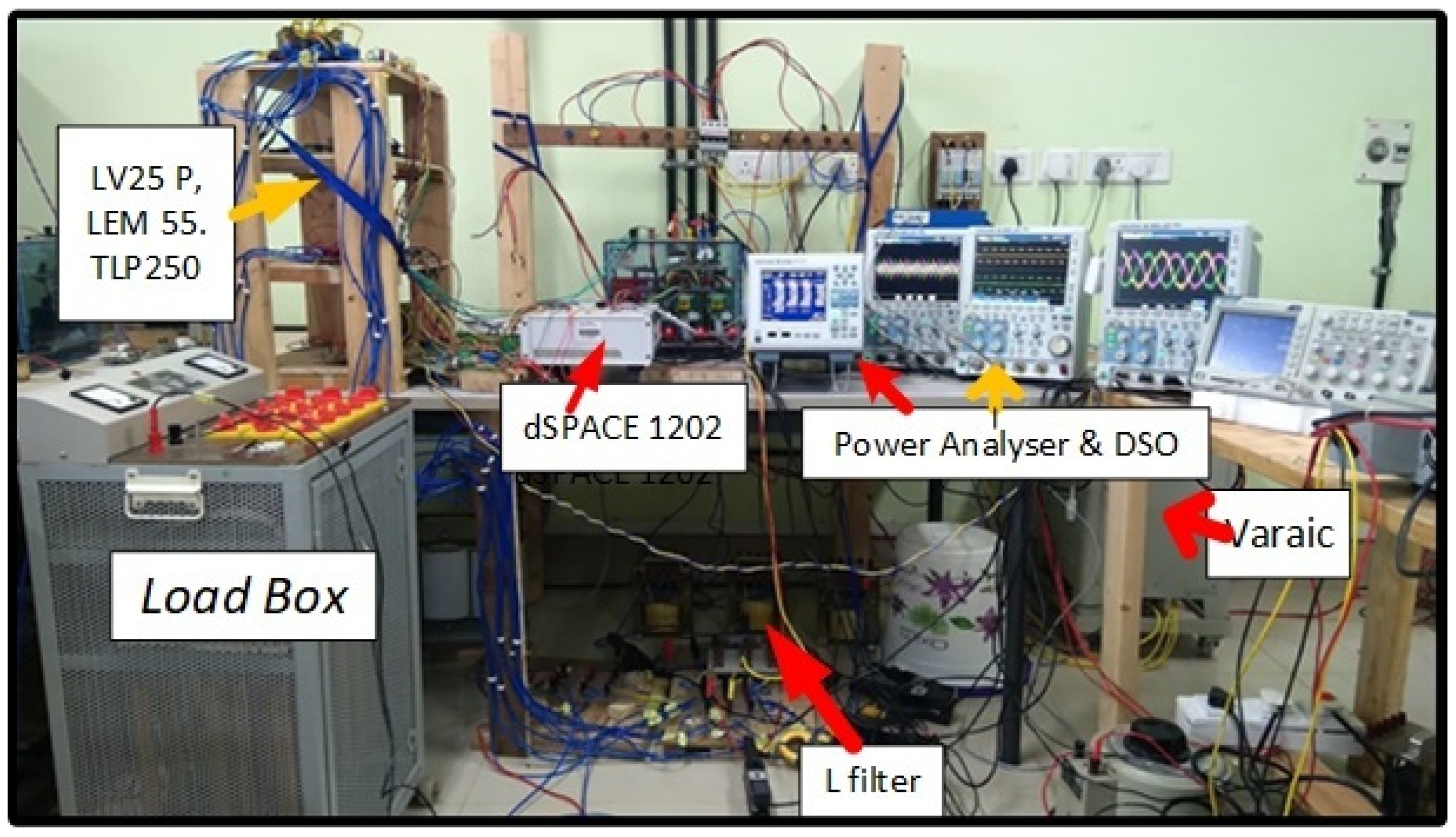
  • Hardware validation of the proposed work is conducted in the laboratory for athree-phase three-leg four-wire grid interfacing DSTATCOM with the help of dSPACE MicroLabBox.
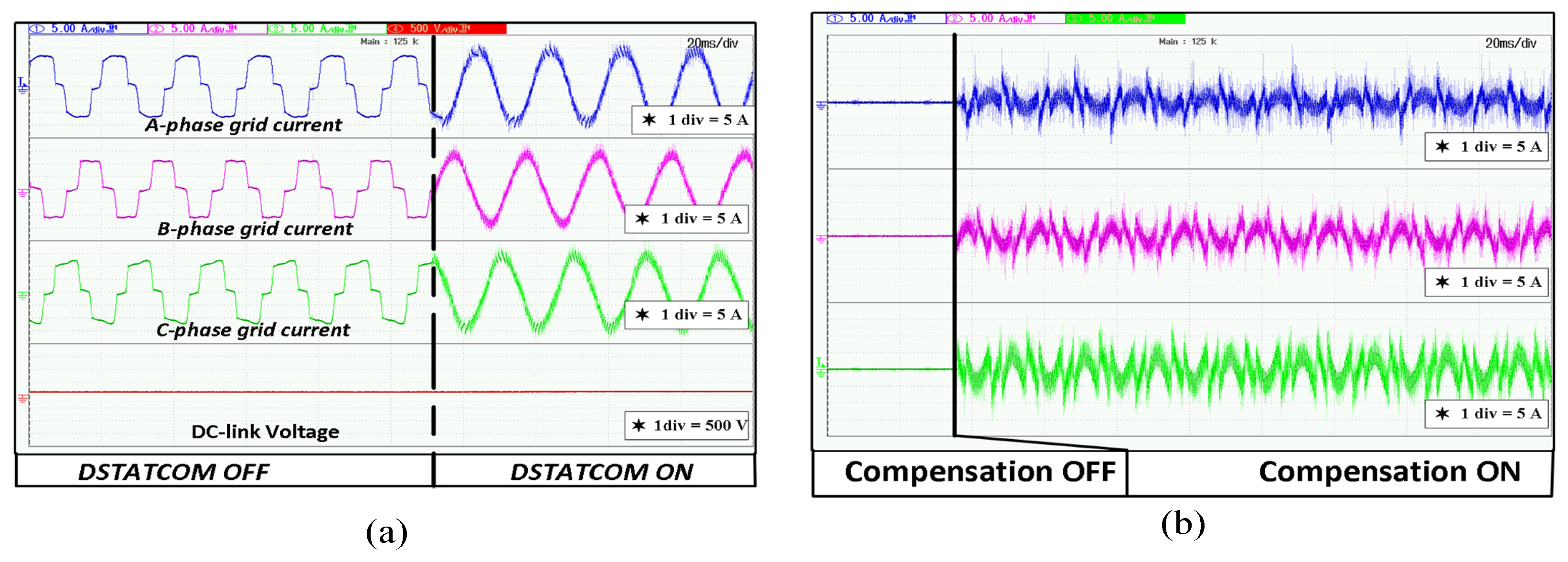
  • Mitigation of the power quality issues such as harmonic elimination, compensation of reactive power, balancing grid-side current during voltage sag, and swell.
  • Maintaining unity power factor operation at grid-side.
  • Reduction in lower-order harmonics from grid currents under steady-state and transient conditions.
  • A comparative analysis of the proposed controller with the exiting controller such as APSA and RIP-APSA is conducted in terms of total harmonic distortion (THD), convergence, steady-state error, sample time, and computation complexity.
This paper is organized into five sections: Section 2 describes the mathematical description in cooperating with DSTATCOM, Section 3 describes the experimental verification and its results, and Section 4 represents the comparison results with exiting control structures. The conclusion is presented in Section 5.

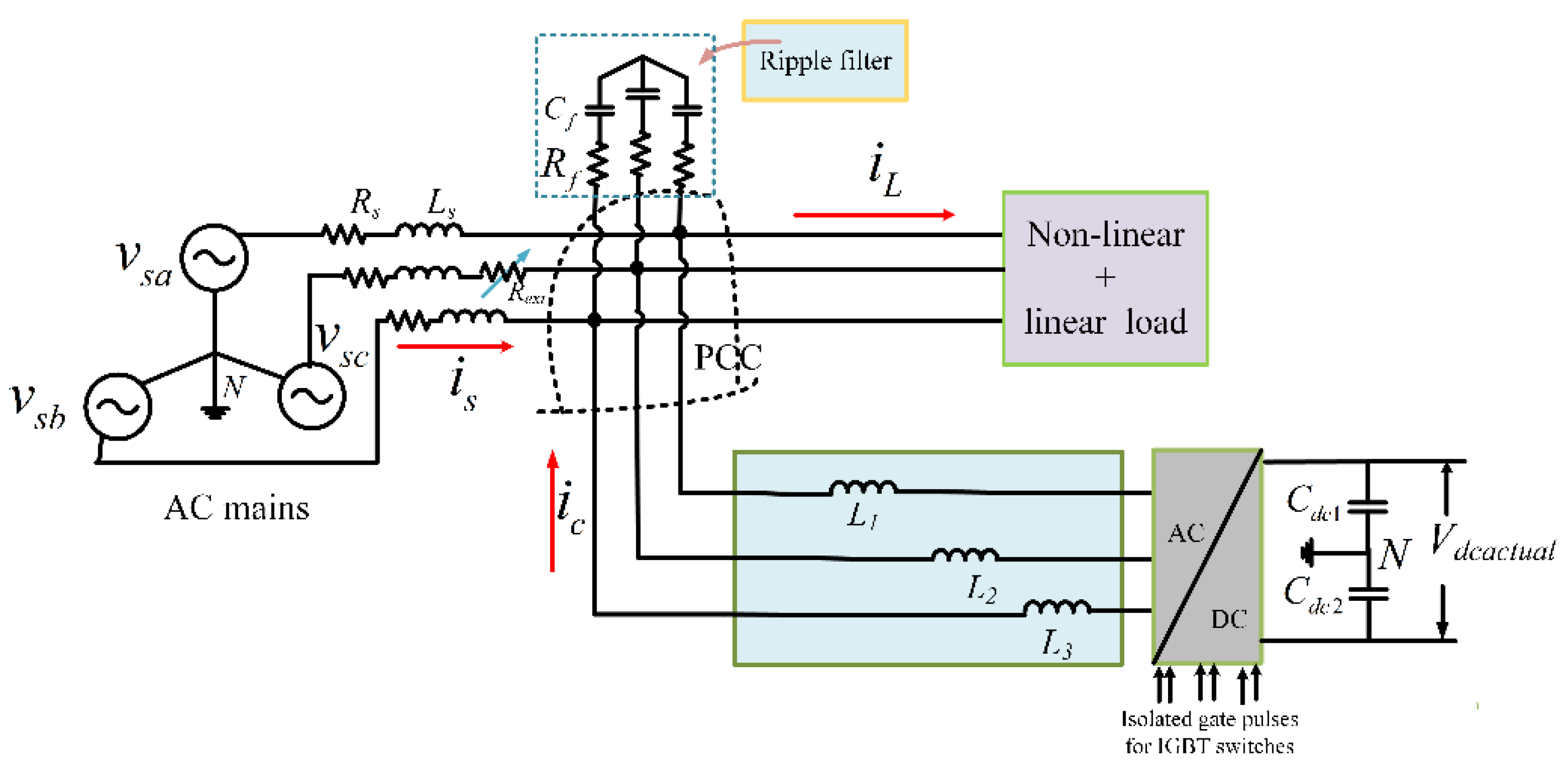
2. DSTATCOM Based on CSS-RIP-APSA Algorithm

A schematic diagram of power exchange between DSTATCOM and the utility grid is shown in Figure 1. DSTATCOM draws active power from the grid to charge the capacitor and deliver reactive power to it. A block diagram of a three-phase four-wire neutral clamped DSTATCOM is illustrated in Figure 2. A three-phase unbalance utility is connected to a three-phase non-linear load and a linear RL load. The DSTATCOM is built with a three-phase voltage source converter (VSC) and two series-connected DC capacitors. The dc capacitor’s midpoint is linked to the neutral of the utility and the load neutral. At PCC, a three-phase inductive filter is connected.

Control Structure

The proposed control structure for the grid-connected DSTATCOM is shown in Figure 3.
As feedback signals, the PCC line voltages ( v s a b , v s b c ), the load currents ( i l a , i l b , i l c ), and DC-link voltage ( V d c a c t u a l ) are measured. The measured PCC line voltages are utilized to estimate three-phase voltages as
v s a = 2 v s a b + v s b c 3 , v s b = v s b c + v s a b 3 , v s c = ( v s b c + v s a b ) 3
Positive sequence voltages ( v p a , v p b , v p c ) of the unbalance grid are given as
[ v p a v p b v p c ] = [ 1 α 2 α α 1 α 2 α 2 α 1 ] [ v s a v s b v s c ]
where α = 1 120 ° and α 2 = 1 240 ° . The amplitude and in-phase ( u p a , u p b , u p c ) templates are estimated using these PCC voltages as follows
V t = 0.816 × v p a 2 + v p b 2 + v p c 2
where the amplitude of the terminal voltage is represented by V t .
u p a = v p a × 1 V t ; u p b = v p b × 1 V t ; u p c = v p c × 1 V t
Again, the unit templates for the quadrature component are computed as
u q a = 0.577 × ( u p c u p b )
u q b = 0.288 × ( 3 * u p a + u p b u p c )
u q c = 0.288 × ( u p b 3 u p a u p c )
Vector ψ ( i ) represents the input repressor vector, and vector i l ( i ) represents the desired input vectors, which are denoted as ψ ( i ) = [ ψ ( i ) ψ ( i 1 ) ψ ( i n + 1 ) ] T and i l ( i ) = [ i l ( i ) , i l ( i 1 ) i l ( i n + 1 ) ] , where i signifies the time index and n denotes the projection order. As a consequence, he difference between the input vector and estimated vector is given as
η ( i ) = i l ( i ) ψ T Y ( i )
where, Y ( i ) is weight vector determined from the CSS-RIP-APSA, and load current ( i l ) is treated as desired input.
The weight updating equation for CSS-RIP-APSA with regularization at ith sample period is formulated as in [26].
Y ( i ) = Y ( i 1 ) + ρ Ψ ( i ) G ( i ) s g n [ η ( i ) ] s g n [ η T ( i ) ] Ψ T ( i ) G ( i ) G ( i ) Ψ ( i ) s g n [ η ( i ) ] + δ
where ρ ( i ) = [ ζ ( i ) τ 1 + ( 1 ζ ( i ) ) τ 2 ] , τ 1 and τ 2 are different step sizes of APSA filter, whereas ξ is defined as { ξ = 0 α ln ( D + 1 D 1 ) ξ = 1 α ln ( D + 1 D 1 ) o r   e l s e ζ ( i ) = D 1 + e σ ( i ) D 1 2
D = 2 and σ ( i ) = σ ( i 1 ) + ζ σ ( ζ 1 ζ 2 ) [ ζ ( i ) τ 1 + ( 1 ζ ( i ) ) τ 2 ] Ψ ( i ) G ( i ) s g n [ η ( i ) ] s g n [ η T ( i ) ] Ψ T ( i ) G ( i ) G ( i ) Ψ ( i ) s g n [ η ( i ) ] + δ , δ = 0.01 is the constant value. G ( i ) = d i a g { g 0 ( i ) g L 1 ( i ) } is a diagonal proportionate matrix, and ψ ( i ) is input load current matrix. The input vector ψ ( k ) consists mostly of fundamental active component weighted values ( Y p a , Y p b , Y p c ), unit vectors (in-phase unit vectors), and reactive component weighted values ( Y q a , Y q b , Y q c ) with respect to the load currents ( i l a , i l b , i l c ) provided in Equations (10)–(15). Equation (9) is modified to obtain updated active and reactive weight components as
Y p a ( i ) = Y p a ( i 1 ) + [ ζ ( i ) τ 1 + ( 1 ζ ( i ) ) τ 2 ] Ψ l a ( i ) G ( i ) s g n [ η a ( i ) ] s g n [ η a T ( i ) ] Ψ l a T ( i ) G ( i ) G ( i ) Ψ l a ( i ) s g n [ η a ( i ) ] + δ
Y p b ( i ) = Y p b ( i 1 ) + [ ζ ( i ) τ 1 + ( 1 ζ ( i ) ) τ 2 ] Ψ l b ( i ) G ( i ) s g n [ η b ( i ) ] s g n [ η b T ( i ) ] Ψ l b T ( i ) G ( i ) G ( i ) Ψ l b ( i ) s g n [ η b ( i ) ] + δ
Y p c ( i ) = Y p c ( i 1 ) + [ ζ ( i ) τ 1 + ( 1 ζ ( i ) ) τ 2 ] Ψ l c ( i ) G ( i ) s g n [ η c ( i ) ] s g n [ η c T ( i ) ] Ψ l c T ( i ) G ( i ) G ( i ) Ψ l c ( i ) s g n [ η c ( i ) ] + δ
Y q a ( i ) = Y q a ( i 1 ) + [ ζ ( i ) τ 1 + ( 1 ζ ( i ) ) τ 2 ] Ψ l a ( i ) G ( i ) s g n [ η a ( i ) ] s g n [ η a T ( i ) ] Ψ l a T ( i ) G ( i ) G ( i ) Ψ l a ( i ) s g n [ η a ( i ) ] + δ
Y q b ( i ) = Y q b ( i 1 ) + [ ζ ( i ) τ 1 + ( 1 ζ ( i ) ) τ 2 ] Ψ l b ( i ) G ( i ) s g n [ η b ( i ) ] s g n [ η b T ( i ) ] Ψ l b T ( i ) G ( i ) G ( i ) Ψ l b ( i ) s g n [ η b ( i ) ] + δ
Y q c ( i ) = Y q c ( i 1 ) + [ ζ ( i ) τ 1 + ( 1 ζ ( i ) ) τ 2 ] Ψ l c ( i ) G ( i ) s g n [ η c ( i ) ] s g n [ η c T ( i ) ] Ψ l c T ( i ) G ( i ) G ( i ) Ψ l c ( i ) s g n [ η c ( i ) ] + δ
The average per phase fundamental active weight component is calculated from (10) to (12) as follows
Y l p a = 1 3 × [ Y p a + Y p b + Y p c ]
The load current consists of harmonic current, reactive current, and active current. To operate at unity power factor, the compensator must inject the harmonic and reactive components of the load current in such a way that the source current equals the difference between the load current and compensation current. The reactive and harmonic components of the load current are combined together to form the compensating current. This ensures that the source current carries only the fundamental active component of the load current. The switching loss component is associated by the operation of the compensator with respect to the rms value of the PCC voltage. Here, loss component ( Y c p l o s s ) is supplied by the grid through injecting extra active power into the system. This loss component ensures that constant DC-link voltage is maintained by the proportional-integral (PI) controller at the dc bus of DSTATCOM. By comparing the DC-link voltage reference value ( V d c r e f ) with the actual DC-link voltage ( V d c a c t u a l ), the loss parameter of the DSTATCOM is calculated. This signal representing the loss component is passed through a proportional-integral (PI) controller to maintain the DC-link voltage at its desired set value. It is calculated at the i t h sample time as
Y c p l o s s ( i ) = Y c p l o s s ( i 1 ) + K p 1 [ V d c * ( i ) V d c * ( i 1 ) ] + K i 1 V d c * ( i )
where V d c * ( i ) = V d c r e f 2 V d c a c t u a l . The net weight active reference grid currents are calculated as
Y s p = Y l p a + Y c p l o s s
For unity power factor operation, the unity current templates are in phase with the supply voltage. The active component of the generated reference current is written as
i p a * = Y s p × U p a ; i p b * = Y s p × U p b ; i p c * = Y s p × U p c
It should be emphasized that the grid current must follow the generated reference current and does not have any zero-sequence components. For zero voltage regulation (ZVR), the reactive reference current can be found from the voltage control loop with PI controller output. The steps are provided as follows
V t e r r o r ( i ) = V t * ( i ) V t ( i )
Y c q ( i ) = Y c q ( i 1 ) + K p 2 [ V ( i ) t e r r o r V ( i 1 ) t e r r o r ] + K i 2 V ( i ) t e r r o r
The average reactive weight of the fundamental component is reduced to the AC loss component, yielding the reactive weight component of the reference grid current, i.e.,
Y s q = Y c q Y l q a
where Y l q a = 1 3 × [ Y q a + Y q b + Y q c ] . The reactive component of grid current is determined as follows
i q a * = u q a × Y s q ; i q b * = u q b × Y s q ; i q c * = u q c × Y s q
As a consequence, the following grid reference currents are computed as
i s a * = i p a * + i q a * ; i s b * = i p b * + i q b * ; i s c * = i p c * + i q c *
The hysteresis current controller generates DSTATCOM gate pulses. Subtraction of the measured grid current ( i s a , i s b , i s c ) from the grid reference currents ( i s a * , i s b * , i s c * ) yields the error.

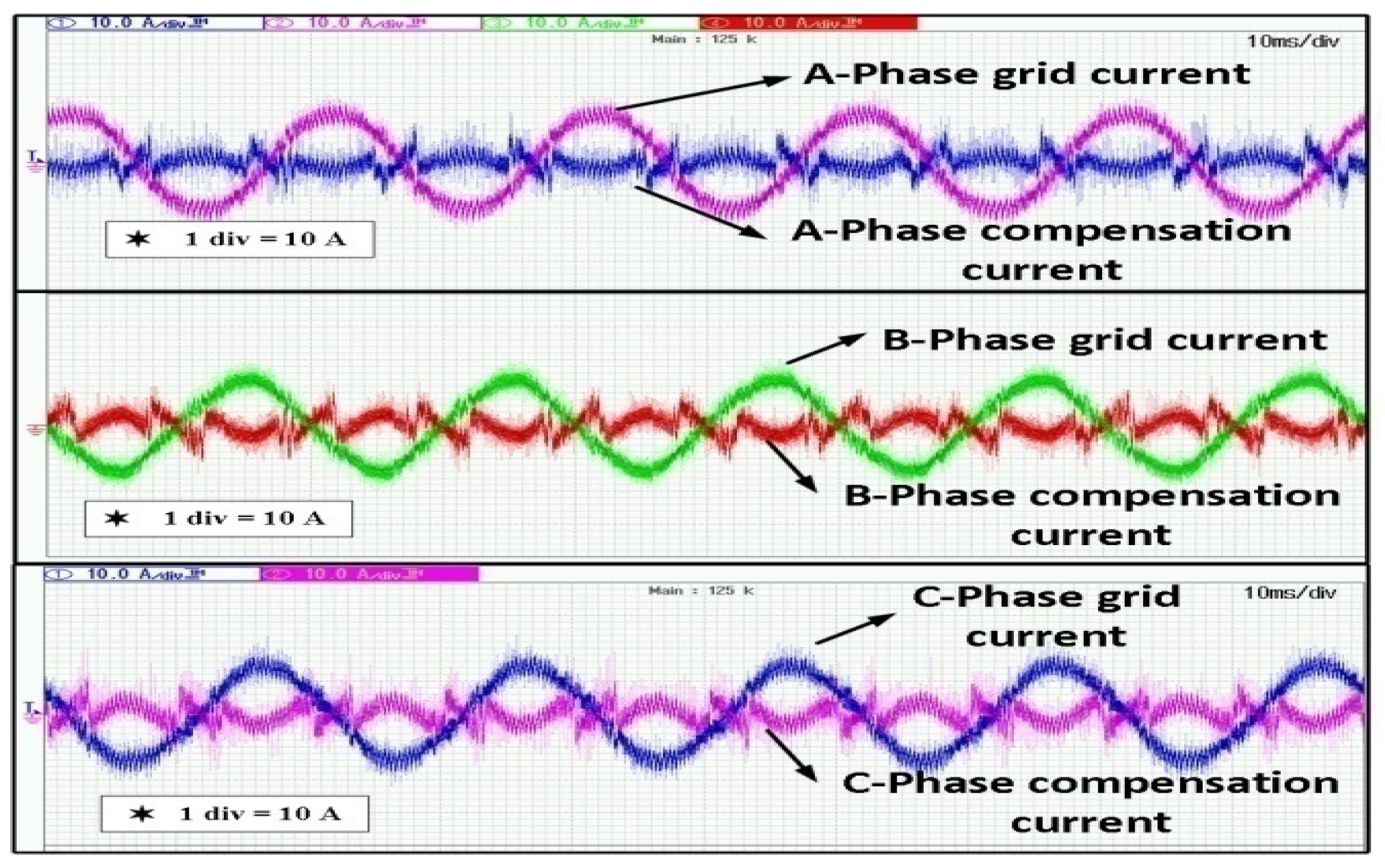
3. Results and Discussion

The efficiency of the proposed CSS-RIP-APSA-based control algorithm for prototype DSTATCOM has been carried out using a DSP-based processor (dSPACE 1202). The test results were analyzed using a four-channel YOKOGAWA DSO-DLM2024 digital storage oscilloscope and YOKOGAWA DSODLM2024 power analyzer. The dynamic performance of the proposed system was analyzed in the presence of an unbalanced supply voltage and sudden changes in the loading conditions. The sampling time was set to 50 μs. Figure 4 depicts the experimental setup. The experimental parameter details have been given in the Appendix A.

3.1. Case 1

The unbalance grid voltage is supplied to a three-phase non-linear and linear load. To create an unbalance grid in the laboratory, external resistances are added in series with the input voltage. A rectifier is connected to a restive and inductive load to form a non-linear load. The nature of the unbalance grid voltage and the non-linear load current is shown in Figure 5a,b, respectively. The load draws non-linear current from the source, which increases the THD of the grid current. With the proposed techniques, the grid current becomes sinusoidal as shown in Figure 6a. To fulfill the load demand, compensation current is provided from DSTATCOM as shown in Figure 6b. Figure 7a shows the results of the power analyzer before the DSTATCOM is connected. It can be seen that 0.933 kW active power and 256 VAR of reactive power are delivered to the load from the grid. It can be observed from Figure 7b that with the operation of the DSTATCOM, the reactive power supplied from the grid decreases from 256 VAR to 81 VAR.As a consequence, the THD of the grid current of the compensated system is lower compared to the uncompensated system.
Figure 8a–c shows the THD of three-phase grid currents and grid voltages. The THD of the compensated grid currents are 3.66%, 4.56%, and 3.92%, respectively. The THD of the compensated grid voltages are 1.80%, 2.9%, and 2.13% respectively. Here, it is noticed that the THD in the grid compensated voltages are less due to the elimination of the third harmonic in the neutral wire. This indicates that the compensation of neutral current is due to less THD in the grid voltages. It is also observed from the power analyzer that DSTATCOM draws 111 Watt active power from the grid to compensate for the switching losses. At the same time, it delivered 175 VAR into the system in order to compensate for the harmonic current and reactive power in the system. Furthermore, the grid current is in the opposite phase with the compensation current flowing from the DSTATCOM as shown in Figure 9. It can be ensured that the compensation current has the ability to cancel out all of the harmonic components present in the grid current, i.e., particularly dominant third harmonic components.

3.2. Case 2

The performance and robustness of the proposed algorithm is observed by removing one of the input phases (phase-B) of the load, resulting in unbalanced grid voltage.As a consequence, the three-phase non-linear load functions like a single-phase non-linear load as illustrated in Figure 10a, which reduces the demand of the non-linear load current. Thus, the compensation current drawn from DSTATCOM is also reduced, as illustrated in Figure 10b. Therefore, the compensation current in phase-B is nearly sinusoidal in nature.
Figure 11a,b shows the power flow analysis after and before compensation, respectively.It is observed that the initial active power requirement is 0.558 kW and the reactive power is 0.303 kVAR. When the DSTATCOM is operational, the active power flow from the grid rises to 0.707 kW to support the DC-link voltage and system losses but the reactive power reduces to just 0.060 kVAR. This implies that the reactive power burden on the grid is decreasing. Furthermore, grid current hasan equal magnitude with respect to other phases during the time when the phase-B load is removed.
The THDs in all three phases of the grid currents are 2.7%, 4.9%, and 2.7%, as illustrated in Figure 12a–c, respectively. It is also noticed that the THDs of grid voltages are 2.1%, 2.7%, and 2.6% in all three phases, respectively.Figure 13a shows the DC-link voltage and the grid currents of the three phases before compensation, after compensation, and during the faulty condition. Figure 13b shows the zoomed view of Figure 13a before and after compensation of the grid current. Here, it is noticed that currents in all three phases are sinusoidal after compensation and DC-link voltage increases from 101 V to 161 V. Figure 13c illustrates the DC-link voltages and grid currents in a faulty condition. It is also a zoomed view of mode 2 of Figure 13a. It can be observed that the DC-link voltage increases from 161 V to 180 V during fault conditions. At the same time, all three phases of grid currents become sinusoidal due to the compensation provided by DSTATCOM. Figure 14a,b shows the vector diagram of grid voltage and current during the faulty condition.

4. Comparison

The performance of extracting the fundamental component of load current using the suggested CSS-RIP-APSA control algorithm and other adaptive approachesat similar ratings under identical situations is demonstrated in Figure 15. It can be shown that extraction of the fundamental signal by the suggested CSS-RIP-APSA offers a quick response as well as reduced oscillation as compared to APSA [11] and RIP-APSA [15]. Moreover, the above two algorithms’ adaptive controls, under transient scenarios, have large oscillations and more time to stabilize in comparison with the proposed CSS-RIP-APSA control algorithm.

5. Conclusions

A control strategy based on the CSS-RIP-APSA algorithm has been developed for the mitigation of third harmonic as well as other harmonics present in the system. In a three-phase four-wire system, third harmonic current flows in the neutral wire cause overloading and overheating, and line losses, and negatively influence system performance in the distribution system. The proposed control algorithm is considered to be a new topology for the modern power system. It has advantages of cost-effectiveness as well as a fast dynamic response in terms of achieving fast-tracking error. It is also helpful in reactive power sharing in between load and DSTATCOM without being dependent on the grid. The developed control algorithm is implemented to generate the driving pulses for the DSTATCOM. The suggested CSS-RIP-APSA algorithm has a great performance compared to traditional adaptive filters in terms of harmonics mitigation, convergence speed, computational complexity, and error minimization. To validate the performances, the experimental results of the proposed algorithm are presented under both transient and steady-state conditions.
The feature of the CSS-RIP-APSA algorithm has the ability to segregate the fundamental and higher-order components of grid current without introducing a phase delay and magnitude reduction. The elicitation of fundamental components and the detection of harmonics without PLL is presented in this paper. This method gets rid of the delay attached with different filters and also solves the issues arising out of the influence of detection of PLL accurately, increasing the speed of the dynamics response. Furthermore, the THD of the grid current is maintained within the IEEE-519 standard. The test results corroborated the authenticity of the proposed controller. This work can be extended for grid integration of renewable resources such as photovoltaic and wind. This helps the inverter to transfer the active power and reactive power, and to reduce the dependency on the utility.

Author Contributions

The contribution to various aspects of this research paper by different authors are as follows.Conceptualization—A.D. and P.K.H.; Methodology—A.D.; Software—A.D.; Validation—A.D.; Formal analysis—A.D., S.k.O., and D.P.B.; Investigation—A.D. and D.P.B.; Resources—A.D., A.K.N. and M.K.S.; Writing—A.D., S.B. (Siddhartha Behera), S.B. (Siddharth Behera) and A.K.B.; Writing—review and editing, D.P.B., S.B.M., and T.H.; Visualization—A.D., P.K.H., and M.K.S.; Supervision—D.P.B. and P.K.H. All authors have read and agreed to the published version of the manuscript.

Funding

This research received no external funding.

Institutional Review Board Statement

Not applicable.

Informed Consent Statement

All individuals included in this section have consented to the acknowledgement.

Data Availability Statement

The study did not report any data.

Acknowledgments

The authors heartily acknowledge the administrativeand experimental support provided by the Electrical Engineering Department of IIT, Patna during the whole tenure of the laboratory work carried out for this paper.

Conflicts of Interest

The authors declare no conflict of interest.

Appendix A

EXPERIMENTAL SETUP PARAMETERS
System QuantitiesValues
Unequal Source voltage (rms)41 V, 31 V, 41 V rms L-N, 50 Hz
Feeder impedance R s = 0.3 ohm, L s = 0.3 mH, R s / X s = 3.185
PI tuning parameter K p 1 = 0.1, K i 1 = 0.001; K p 2 = 0.05, K i 2 = 0.005
Non-linear load3-Φ rectifier with RL load of 4 ohm and 40 mH
DSTATCOM parameter V d c r e f e r e n c e = 165 V, C d c = 2200 µF, L f = 0.55 mH

References

  1. Rafi, F.H.M.; Hossain, M.J.; Town, G.; Lu, J. Smart voltage source inverters with a novel approach to enhance neutral-current compensation. IEEE Tran. Ind. Electron. 2019, 66, 3518–3529. [Google Scholar] [CrossRef]
  2. Akagi, H.; Watanabe, E.H.; Aredes, M. Instantaneous Power Theory and Applications to Power Conditioning; John Wiley & Sons: Hoboken, NJ, USA, 2017. [Google Scholar]
  3. Sahu, M.K.; Biswal, M.; Malla, J.M.R. THD analysis of a seven, nine, and eleven level cascaded H-bridge multilevel inverter for different loads. Teh. Glas. 2020, 14, 513–522. [Google Scholar]
  4. Malla, S.G.; Malla, J.M.R.; Malla, P.; Sreekanth, R.; Kumar, D.S.; Sahu, M.K.; Subudhi, P.K.; Awad, H. Coordinated power management and control of renewable energy sources based smart grid. Int. J. Emerg. Electr. Power IJEEPS 2021, 22, 18. [Google Scholar] [CrossRef]
  5. Chen, J.; Zhu, R.; Ibrahim, I.; O’Donnell, T.; Liserre, M. Neutral current optimization control for smart transformer-fed distribution system under unbalanced loads. IEEE J. Emerg. Sel. Top. Power Electron. 2020, 9, 1696–1707. [Google Scholar] [CrossRef]
  6. Park, K.W.; Seo, H.C.; Kim, C.H.; Jung, C.S.; Yoo, Y.P.; Lim, Y.H. Analysis of the neutral current for two-step-type poles in distribution lines. IEEE Trans. Power Del. 2009, 24, 1483–1489. [Google Scholar] [CrossRef]
  7. Sreenivasarao, D.; Agarwal, P.; Das, B. Neutral current compensation in three-phase, four-wire systems: A review. Electr. Power Syst. Res. 2012, 86, 170–180. [Google Scholar] [CrossRef]
  8. Rivera, M.; Rodriguez, J.; Garcia, C.; Pena, R.; Espinoza, J. A simple predictive voltage control method with unity displacement power factor for four-leg indirect matrix converters. In Proceedings of the 15th International Power Electronics and Motion Control Conference (EPE/PEMC), Novi Sad, Serbia, 4–6 September 2012; pp. 2–6. [Google Scholar]
  9. Ge, J.; Shuai, Z.; Shen, X.; Feng, Y.; Zhao, H.; Shen, Y.; Shen, Z.J. Asymmetrical Voltage Support Control of Three-Phase Four-Wire Inverters with Zero Active Power Oscillation during Grid Faults. In Proceedings of the 2021 IEEE Energy Conversion Congress and Exposition (ECCE), Vancouver, BC, Canada, 10–14 October 2021; pp. 906–911. [Google Scholar]
  10. Zhu, Z.; Chen, W. Zero sequence voltage and current control in four-wire grids-fed by grid-forming inverters. CSEE J. Power Energy Syst. 2020, 6, 8. [Google Scholar] [CrossRef]
  11. Ouyang, S.; Liu, J.j.; Chen, H. Arm Current Stress Reduction Technique for a Delta-Connected Solid State Transformer using Zero-Sequence Current Injection. IEEE Trans. Power Electron. 2021, 36, 12234–12250. [Google Scholar] [CrossRef]
  12. Wu, J.C.; Jou, H.L.; Wu, K.D.; Xiao, S.T. Single-phase inverter-based neutral-current suppressor for attenuating neutral current of three-phase four-wire distribution power system. IET Gener. Transm. Distrib. 2012, 6, 577–583. [Google Scholar] [CrossRef]
  13. Saim, A.; Houari, A.; Ahmed, M.A.; Djerioui, A.; Machmoum, M.; Guerrero, J.M. Adaptive reference trajectory for power quality enhancement in three-phase four-wire standalone power supply systems with nonlinear and unbalanced loads. IEEE J. Emerg. Sel. Top. Power Electron. 2020, 8, 1593–1603. [Google Scholar] [CrossRef]
  14. Pan, D.; Wang, X.; Liu, F.; Shi, R. Transient stability of voltage-source converters with grid-forming control: A design-oriented study. IEEE J. Emerg. Sel. Top. Power Electron. 2019, 8, 1019–1033. [Google Scholar] [CrossRef]
  15. Kumar, A.; Kumar, P. Power Quality Improvement for Grid-connected PV System Based on Distribution Static Compensator with Fuzzy Logic Controller and UVT/ADALINE-based Least Mean Square Controller. J. Mod. Power Syst. Clean Energy 2021, 9, 1289–1299. [Google Scholar] [CrossRef]
  16. Li, Z.; Li, D.; Xu, X.; Zhang, J. New normalized LMS adaptive filter with a variable regularization factor. J. Syst. Eng. Electron. 2019, 30, 259–269. [Google Scholar]
  17. Ferrer, M.; de Diego, M.; Piñero, G.; Gonzalez, A. Affine Projection Algorithm Over Acoustic Sensor Networks for Active Noise Control. IEEE/ACM Trans. AudioSpeech Lang. Process. 2020, 29, 448–461. [Google Scholar] [CrossRef]
  18. Jeong, J.J. A robust affine projection algorithm against impulsive noise. IEEE Signal Process. Lett. 2020, 27, 1530–1534. [Google Scholar] [CrossRef]
  19. Cheng, H.; Xia, Y.; Huang, Y.; Yang, L.; Mandic, D.P. A normalized complex LMS based blind I/Q imbalance compensator for GFDM receivers and its full second-order performance analysis. IEEE Trans. Signal Process. 2018, 66, 4701–4712. [Google Scholar] [CrossRef]
  20. Ma, W.; Zheng, D.; Tong, X.; Zhang, Z.; Chen, B. Proportionate NLMS with unbiasedness criterion for sparse system identification in the presence of input and output noises. IEEE Trans. Circuits Syst. II 2018, 65, 1808–1812. [Google Scholar] [CrossRef]
  21. Zhang, T.; Jiao, H.Q.; Lei, Z.C. Individual-activation-factor memory proportionate affine projection algorithm with evolving regularization. IEEE Access 2017, 5, 4939–4946. [Google Scholar] [CrossRef]
  22. Albu, F.; Kwan, H.K. Memory improved proportionate affine projection sign algorithm. Electron. Lett. 2012, 48, 1279–1281. [Google Scholar] [CrossRef]
  23. Yang, Z.; Zheng, Y.R.; Grant, S.L. Proportionate affine projection sign algorithms for network echo cancellation. IEEE Trans. AudioSpeech Lang. Process. 2011, 19, 2273–2284. [Google Scholar] [CrossRef]
  24. Das, R.L.; Chakraborty, M. Improving the performance of the PNLMS algorithm using l1norm regularization. IEEE/ACM Trans. AudioSpeech Lang. Process. 2016, 24, 1280–1290. [Google Scholar] [CrossRef]
  25. Huang, X.; Li, Y.; Zakharov, Y.V.; Li, Y.; Chen, B. Affine-Projection Lorentzian Algorithm for Vehicle Hands-Free Echo Cancellation. IEEE Trans. Veh. Technol. 2021, 70, 2561–2575. [Google Scholar] [CrossRef]
  26. Huang, F.; Zhang, J.; Pang, Y. A novel combination scheme of proportionate filter. Signal Process. 2018, 143, 222–231. [Google Scholar] [CrossRef]
Figure 1. Schematic diagram of power exchange.
Energies 15 00197 g001
Figure 2. Configuration of grid integrated three-phase neutral clamped DSTATCOM.
Energies 15 00197 g002
Figure 3. Block diagram of CSS-RIP-APSA-based control algorithm.
Energies 15 00197 g003
Figure 4. An experimental setup developed at the laboratory.
Energies 15 00197 g004
Figure 5. (a) Characteristic of unbalance grid voltage, (b) Non-linear characteristic of load current.
Energies 15 00197 g005
Figure 6. (a) Characteristic of grid current with and without compensation, (b) Compensationcurrent flow from DSTATCOM.
Energies 15 00197 g006
Figure 7. Power quality analysis of the system (a) without compensation (b) with compensation.
Energies 15 00197 g007
Figure 8. THD of grid current (a) phase-A, (b) Phase-B current, (c) Phase-C.
Energies 15 00197 g008aEnergies 15 00197 g008b
Figure 9. Behaviour of grid current with respect to compensation current.
Energies 15 00197 g009
Figure 10. (a) Behavior of load current during transient state, (b) compensation current flow from DSTATCOM during transient operation.
Energies 15 00197 g010
Figure 11. Power analysis during transient (a) after compensation, (b) before compensation.
Energies 15 00197 g011
Figure 12. THD of grid current (a) phase-A, (b) phase-B, (c)phase-C.
Energies 15 00197 g012aEnergies 15 00197 g012b
Figure 13. (a) Analysis of DC-link voltage with grid current during transient period with operation of the DSTATCOM (b) zoomed version of mode-1, (c) zoomed version of mode-2.
Energies 15 00197 g013
Figure 14. Vector analysis of grid voltage with respect to grid current (a) without compensation, (b) with compensation.
Energies 15 00197 g014
Figure 15. Comparison of proposed algorithm with traditional algorithms.
Energies 15 00197 g015
Publisher’s Note: MDPI stays neutral with regard to jurisdictional claims in published maps and institutional affiliations.

